construction - hawaii department of transportation discharge permit to storm drains-construction...
TRANSCRIPT
Construction Best Management
Practices Field Manual
January 2008

THIS PAGE INTENTIONALLY LEFT BLANK
State of Hawaii DOT, Highways Division Construction BMP Field Manual
i January 2008
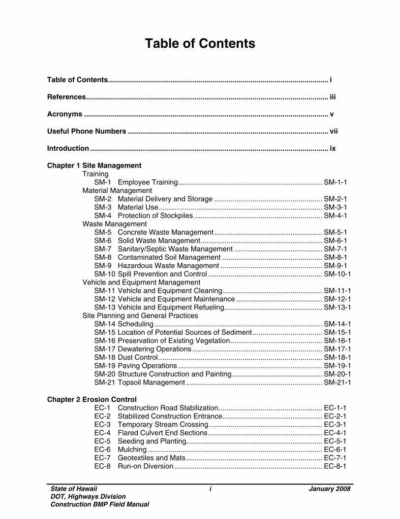
Table of Contents Table of Contents.............................................................................................................. i References......................................................................................................................... iii Acronyms .......................................................................................................................... v Useful Phone Numbers .................................................................................................... vii Introduction ....................................................................................................................... ix Chapter 1 Site Management
Training SM-1 Employee Training........................................................................ SM-1-1
Material Management SM-2 Material Delivery and Storage ...................................................... SM-2-1 SM-3 Material Use.................................................................................. SM-3-1 SM-4 Protection of Stockpiles ................................................................ SM-4-1
Waste Management SM-5 Concrete Waste Management ...................................................... SM-5-1 SM-6 Solid Waste Management............................................................. SM-6-1 SM-7 Sanitary/Septic Waste Management ............................................ SM-7-1 SM-8 Contaminated Soil Management .................................................. SM-8-1 SM-9 Hazardous Waste Management ................................................... SM-9-1 SM-10 Spill Prevention and Control ......................................................... SM-10-1
Vehicle and Equipment Management SM-11 Vehicle and Equipment Cleaning.................................................. SM-11-1 SM-12 Vehicle and Equipment Maintenance ........................................... SM-12-1 SM-13 Vehicle and Equipment Refueling................................................. SM-13-1
Site Planning and General Practices SM-14 Scheduling.................................................................................... SM-14-1 SM-15 Location of Potential Sources of Sediment................................... SM-15-1 SM-16 Preservation of Existing Vegetation.............................................. SM-16-1 SM-17 Dewatering Operations ................................................................. SM-17-1 SM-18 Dust Control.................................................................................. SM-18-1 SM-19 Paving Operations ........................................................................ SM-19-1 SM-20 Structure Construction and Painting ............................................. SM-20-1 SM-21 Topsoil Management .................................................................... SM-21-1 Chapter 2 Erosion Control EC-1 Construction Road Stabilization.................................................... EC-1-1 EC-2 Stabilized Construction Entrance.................................................. EC-2-1 EC-3 Temporary Stream Crossing......................................................... EC-3-1 EC-4 Flared Culvert End Sections ......................................................... EC-4-1 EC-5 Seeding and Planting.................................................................... EC-5-1 EC-6 Mulching ....................................................................................... EC-6-1 EC-7 Geotextiles and Mats .................................................................... EC-7-1 EC-8 Run-on Diversion.......................................................................... EC-8-1
State of Hawaii DOT, Highways Division Construction BMP Field Manual
ii January 2008
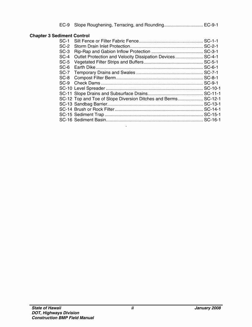
EC-9 Slope Roughening, Terracing, and Rounding............................... EC-9-1 Chapter 3 Sediment Control SC-1 Silt Fence or Filter Fabric Fence................................................... SC-1-1 SC-2 Storm Drain Inlet Protection.......................................................... SC-2-1 SC-3 Rip-Rap and Gabion Inflow Protection ......................................... SC-3-1 SC-4 Outlet Protection and Velocity Dissipation Devices ...................... SC-4-1 SC-5 Vegetated Filter Strips and Buffers............................................... SC-5-1 SC-6 Earth Dike..................................................................................... SC-6-1 SC-7 Temporary Drains and Swales ..................................................... SC-7-1 SC-8 Compost Filter Berm..................................................................... SC-8-1 SC-9 Check Dams ................................................................................. SC-9-1 SC-10 Level Spreader ............................................................................. SC-10-1 SC-11 Slope Drains and Subsurface Drains............................................ SC-11-1 SC-12 Top and Toe of Slope Diversion Ditches and Berms.................... SC-12-1 SC-13 Sandbag Barrier............................................................................ SC-13-1 SC-14 Brush or Rock Filter ...................................................................... SC-14-1 SC-15 Sediment Trap .............................................................................. SC-15-1 SC-16 Sediment Basin............................................................................. SC-16-1
.
State of Hawaii DOT, Highways Division Construction BMP Field Manual
iii January 2008
References City of Knoxville, Engineering Department, Stormwater Engineering Division, Knoxville BMP Manual, May, 2003. City of Reno, Truckee Meadows Construction Site Best Management Practices Handbook, February, 2003. Department of Environmental Services, City and County of Honolulu in cooperation with The General Contractors Association of Hawaii, Best Management Practices Manual for Construction Sites in Honolulu, May, 1999. Maryland Department of the Environment, Water Management Administration in association with Soil Conservation Service and State Soil Conservation Committee, 1994 Maryland Standards and Specifications for Soil Erosion and Sediment Control,1994. Prince George’s County, Maryland, Department of Environmental Resource Programs and Planning Division, Low-Impact Development Design Strategies, An Integrated Design Approach, June, 1999. State of California, Department of Transportation, California Storm Water Quality Handbooks, Construction Site Best Management Practices (BMPs) Manual, March, 2003. State of Hawaii, Department of transportation, Hawaii Standard Specifications for Road and Bridge Construction, 2005.

State of Hawaii DOT, Highways Division Construction BMP Field Manual
iv January 2008
THIS PAGE INTENTIONALLY LEFT BLANK
State of Hawaii DOT, Highways Division Construction BMP Field Manual
v January 2008
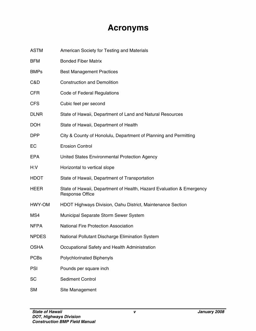
Acronyms ASTM American Society for Testing and Materials BFM Bonded Fiber Matrix BMPs Best Management Practices C&D Construction and Demolition CFR Code of Federal Regulations CFS Cubic feet per second DLNR State of Hawaii, Department of Land and Natural Resources DOH State of Hawaii, Department of Health DPP City & County of Honolulu, Department of Planning and Permitting EC Erosion Control EPA United States Environmental Protection Agency H:V Horizontal to vertical slope HDOT State of Hawaii, Department of Transportation HEER State of Hawaii, Department of Health, Hazard Evaluation & Emergency
Response Office HWY-OM HDOT Highways Division, Oahu District, Maintenance Section MS4 Municipal Separate Storm Sewer System NFPA National Fire Protection Association NPDES National Pollutant Discharge Elimination System OSHA Occupational Safety and Health Administration PCBs Polychlorinated Biphenyls PSI Pounds per square inch SC Sediment Control SM Site Management

State of Hawaii DOT, Highways Division Construction BMP Field Manual
vi January 2008
THIS PAGE INTENTIONALLY LEFT BLANK
State of Hawaii DOT, Highways Division Construction BMP Field Manual
vii January 2008
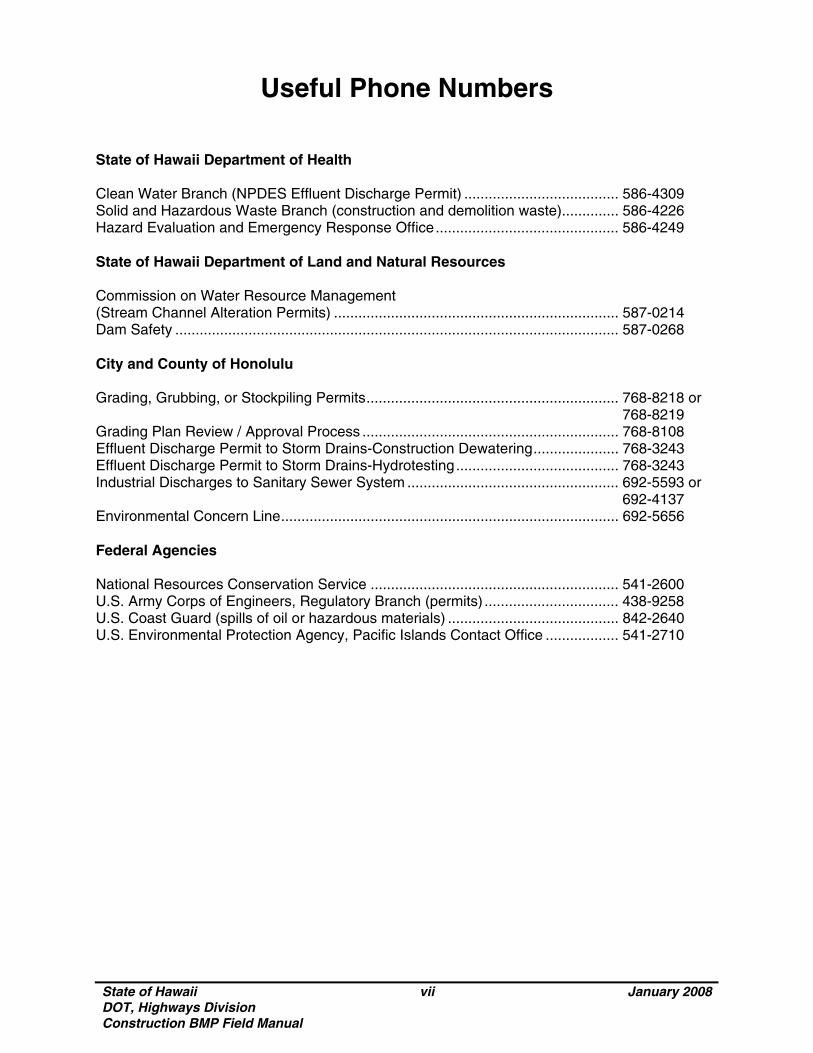
Useful Phone Numbers State of Hawaii Department of Health Clean Water Branch (NPDES Effluent Discharge Permit) ...................................... 586-4309 Solid and Hazardous Waste Branch (construction and demolition waste).............. 586-4226 Hazard Evaluation and Emergency Response Office............................................. 586-4249 State of Hawaii Department of Land and Natural Resources Commission on Water Resource Management (Stream Channel Alteration Permits) ...................................................................... 587-0214 Dam Safety ............................................................................................................. 587-0268 City and County of Honolulu Grading, Grubbing, or Stockpiling Permits.............................................................. 768-8218 or
768-8219 Grading Plan Review / Approval Process ............................................................... 768-8108 Effluent Discharge Permit to Storm Drains-Construction Dewatering..................... 768-3243 Effluent Discharge Permit to Storm Drains-Hydrotesting........................................ 768-3243 Industrial Discharges to Sanitary Sewer System .................................................... 692-5593 or 692-4137 Environmental Concern Line................................................................................... 692-5656 Federal Agencies National Resources Conservation Service ............................................................. 541-2600 U.S. Army Corps of Engineers, Regulatory Branch (permits) ................................. 438-9258 U.S. Coast Guard (spills of oil or hazardous materials) .......................................... 842-2640 U.S. Environmental Protection Agency, Pacific Islands Contact Office .................. 541-2710

State of Hawaii DOT, Highways Division Construction BMP Field Manual
viii January 2008
THIS PAGE INTENTIONALLY LEFT BLANK
State of Hawaii DOT, Highways Division Construction BMP Field Manual
ix January 2008
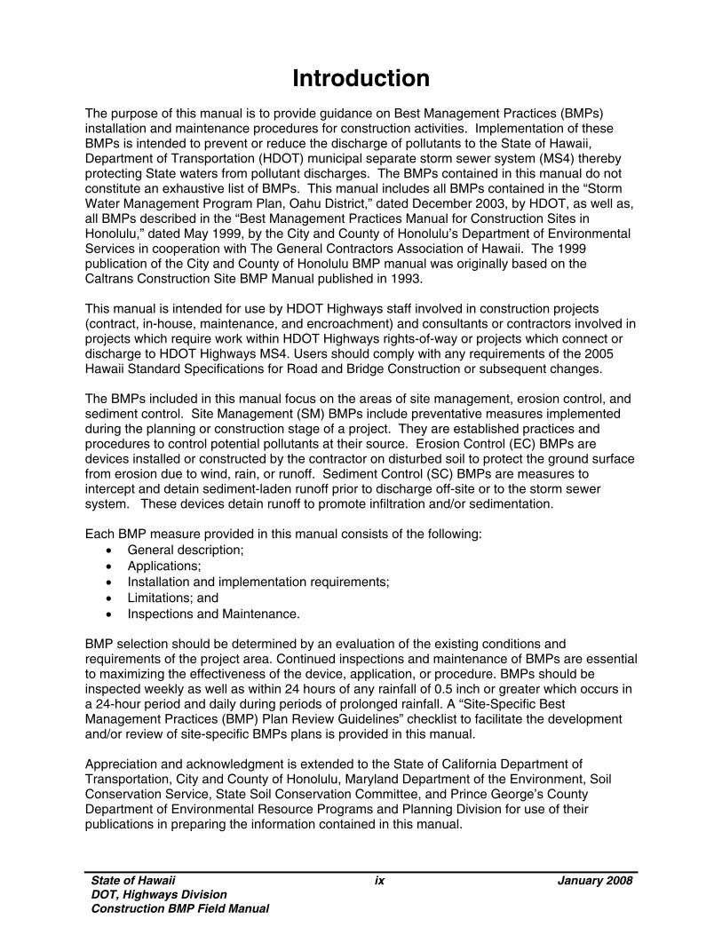
Introduction The purpose of this manual is to provide guidance on Best Management Practices (BMPs) installation and maintenance procedures for construction activities. Implementation of these BMPs is intended to prevent or reduce the discharge of pollutants to the State of Hawaii, Department of Transportation (HDOT) municipal separate storm sewer system (MS4) thereby protecting State waters from pollutant discharges. The BMPs contained in this manual do not constitute an exhaustive list of BMPs. This manual includes all BMPs contained in the “Storm Water Management Program Plan, Oahu District,” dated December 2003, by HDOT, as well as, all BMPs described in the “Best Management Practices Manual for Construction Sites in Honolulu,” dated May 1999, by the City and County of Honolulu’s Department of Environmental Services in cooperation with The General Contractors Association of Hawaii. The 1999 publication of the City and County of Honolulu BMP manual was originally based on the Caltrans Construction Site BMP Manual published in 1993. This manual is intended for use by HDOT Highways staff involved in construction projects (contract, in-house, maintenance, and encroachment) and consultants or contractors involved in projects which require work within HDOT Highways rights-of-way or projects which connect or discharge to HDOT Highways MS4. Users should comply with any requirements of the 2005 Hawaii Standard Specifications for Road and Bridge Construction or subsequent changes. The BMPs included in this manual focus on the areas of site management, erosion control, and sediment control. Site Management (SM) BMPs include preventative measures implemented during the planning or construction stage of a project. They are established practices and procedures to control potential pollutants at their source. Erosion Control (EC) BMPs are devices installed or constructed by the contractor on disturbed soil to protect the ground surface from erosion due to wind, rain, or runoff. Sediment Control (SC) BMPs are measures to intercept and detain sediment-laden runoff prior to discharge off-site or to the storm sewer system. These devices detain runoff to promote infiltration and/or sedimentation. Each BMP measure provided in this manual consists of the following:
• General description; • Applications; • Installation and implementation requirements; • Limitations; and • Inspections and Maintenance.
BMP selection should be determined by an evaluation of the existing conditions and requirements of the project area. Continued inspections and maintenance of BMPs are essential to maximizing the effectiveness of the device, application, or procedure. BMPs should be inspected weekly as well as within 24 hours of any rainfall of 0.5 inch or greater which occurs in a 24-hour period and daily during periods of prolonged rainfall. A “Site-Specific Best Management Practices (BMP) Plan Review Guidelines” checklist to facilitate the development and/or review of site-specific BMPs plans is provided in this manual. Appreciation and acknowledgment is extended to the State of California Department of Transportation, City and County of Honolulu, Maryland Department of the Environment, Soil Conservation Service, State Soil Conservation Committee, and Prince George’s County Department of Environmental Resource Programs and Planning Division for use of their publications in preparing the information contained in this manual.
State of Hawaii DOT, Highways Division Construction BMP Field Manual
x January 2008
Disclaimer
The information presented in this Construction BMP Field Manual was taken from available and most recent sources deemed to be representative of the Best Management Practice and designs for storm water runoff control measures. This manual has been prepared as a reference guideline, however, due to site specific conditions, the selection of the BMPs must be used in conjunction with best professional judgment and sound engineering principles to assure proper function and performance of the BMPs contained herein. The author does not guarantee the accuracy or completeness of this document and will not assume any liability or responsibility for the use of, or for any damages resulting from the use of any information contained herein. The detail and the wording in this manual will not necessarily result in compliance with the Standard Specifications. Application of any BMPs should comply with any requirements of the 2005 Hawaii Standard Specifications for Road and Bridge Construction and subsequent changes.
State of Hawaii DOT, Highways Division Construction BMP Field Manual
SM January 2008
Chapter 1 Site Management
Site Management (SM) BMPs are preventative measures implemented during the planning and/or construction stage of the project, which control potential pollutants at their source through the use of good house-keeping practices. In this chapter:
Training; Material Management; Waste Management; Vehicle and Equipment Management; Site Planning and General Practices.

State of Hawaii DOT, Highways Division Construction BMP Field Manual
SM January 2008
THIS PAGE INTENTIONALLY LEFT BLANK

State of Hawaii DOT, Highways Division Construction BMP Field Manual
SM-1-1 January 2008
Employee Training SM-1
Source: Knoxville BMP Manual, 2003.
Description Training programs ensure that all employees understand the requirements of the Storm Water Management Program Plan as applicable to their responsibilities. Training topics include but are not limited to storm water management, potential contamination sources, and BMPs.
Applications Employees involved in the planning, design, or construction phase
of construction, repair, or maintenance activities within the HDOT Highways rights-of-way.
Implementation Requirements
• Provide storm water management training through courses, seminars, workshops, product demonstrations, employee meetings, posters, and bulletin boards.
• Provide field training programs conducted by trained personnel.
• Maintain commitment and request input from senior DOT and Highways Division management.
• Promote open communication between employees involved in various stages of the projects.
• Improve storm water quality management based on past experience involving water quality problems at construction sites. Implement revised practices and procedures in training.
• Increase employee awareness of requirements and procedures for BMP monitoring and reporting.
• Develop standard operating procedures for storm water quality management.
• Conduct spill drills.
State of Hawaii DOT, Highways Division Construction BMP Field Manual
SM-1-2 January 2008
Employee Training SM-1
Limitations
• Training performance depends on the degree of employee
motivation and incentive to learn about BMP implementation; and
• The availability of staff time to coordinate and conduct training. Inspections and Maintenance
Provide annual training on construction BMP implementation for all employees involved with construction activities.
State of Hawaii DOT, Highways Division Construction BMP Field Manual
SM-2-1 January 2008
Material Delivery and Storage SM-2
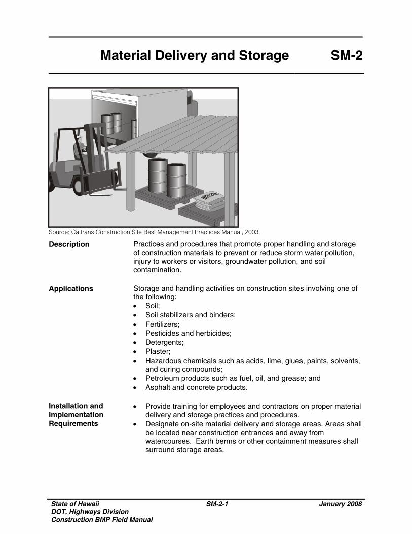
Source: Caltrans Construction Site Best Management Practices Manual, 2003.
Description Practices and procedures that promote proper handling and storage of construction materials to prevent or reduce storm water pollution, injury to workers or visitors, groundwater pollution, and soil contamination.
Applications Storage and handling activities on construction sites involving one of
the following: • Soil; • Soil stabilizers and binders; • Fertilizers; • Pesticides and herbicides; • Detergents; • Plaster; • Hazardous chemicals such as acids, lime, glues, paints, solvents,
and curing compounds; • Petroleum products such as fuel, oil, and grease; and • Asphalt and concrete products.
Installation and Implementation Requirements
• Provide training for employees and contractors on proper material delivery and storage practices and procedures.
• Designate on-site material delivery and storage areas. Areas shall be located near construction entrances and away from watercourses. Earth berms or other containment measures shall surround storage areas.
State of Hawaii DOT, Highways Division Construction BMP Field Manual
SM-2-2 January 2008
Material Delivery and Storage SM-2
Installation and Implementation Requirements (Continued)
• Flammable materials shall comply with the fire codes of Honolulu. Contact the local Fire Marshal for site specific requirements. Refer to the Flammable and Combustible Liquid Code, NFPA30 for more information.
• Maintain accurate and up to date records of material delivered and stored on-site.
• Minimize on-site inventory. • Retain a complete set of material safety data sheets on-site. • Minimize handling of hazardous materials. • Store materials under cover during the rainy season. • Store chemicals, drum, and bagged materials on a pallet and
when possible, under cover in secondary containment. • If drums must be stored in an uncovered area, place them at a
slight angle to minimize ponding of rainwater on the lids to minimize corrosion.
• Hazardous chemicals shall be well-labeled and stored in the original containers.
• Employees with emergency spill cleanup training shall be present during unloading of dangerous materials or liquid chemicals.
• Any significant residual materials remaining on the ground after the completion of construction shall be removed and properly disposed. If the residual materials contaminate the soil, then the contaminated soil shall also be removed and properly disposed.
Limitations Storage sheds shall comply with building and fire code requirements. Inspections and Maintenance
• Storage areas shall be clean and well organized. • An ample supply of spill cleanup materials shall be kept with work
crew supplies. • Conduct weekly inspections of material containers for corrosion. • Conduct weekly inspections of storage areas which may require
repair or replacement.
State of Hawaii DOT, Highways Division Construction BMP Field Manual
SM-3-1 January 2008
Material Use SM-3
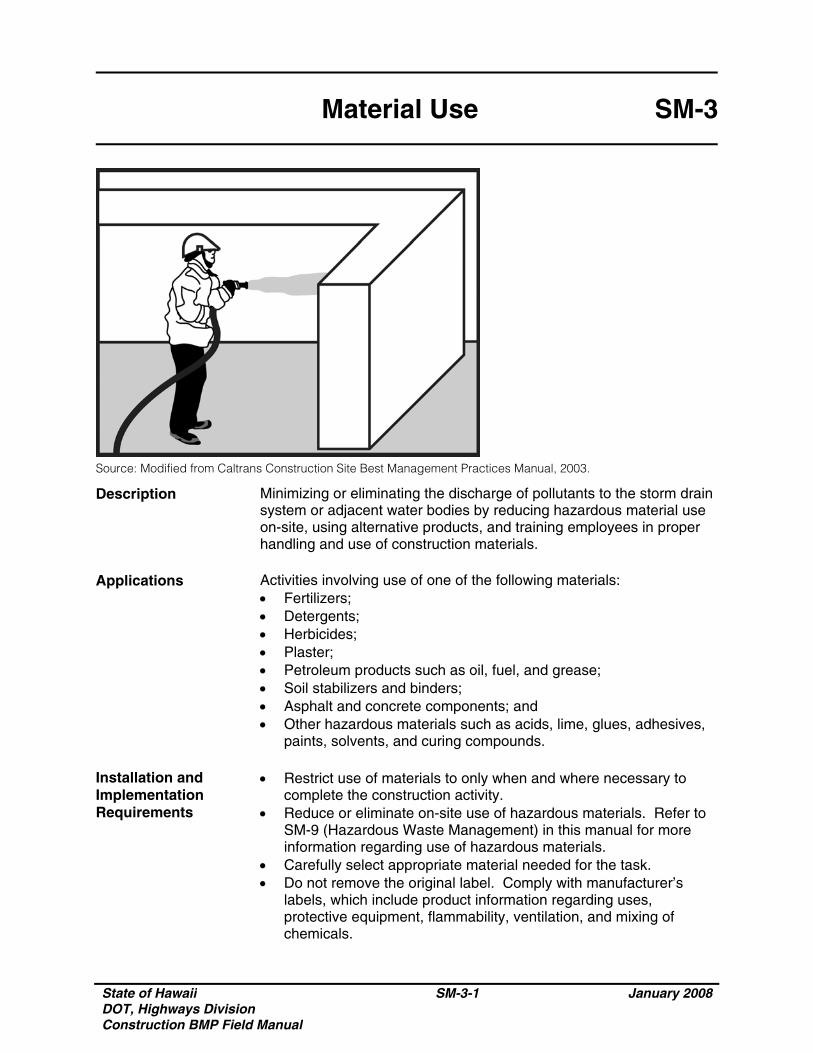
Source: Modified from Caltrans Construction Site Best Management Practices Manual, 2003.
Description Minimizing or eliminating the discharge of pollutants to the storm drain system or adjacent water bodies by reducing hazardous material use on-site, using alternative products, and training employees in proper handling and use of construction materials.
Applications Activities involving use of one of the following materials:
• Fertilizers; • Detergents; • Herbicides; • Plaster; • Petroleum products such as oil, fuel, and grease; • Soil stabilizers and binders; • Asphalt and concrete components; and • Other hazardous materials such as acids, lime, glues, adhesives,
paints, solvents, and curing compounds. Installation and Implementation Requirements
• Restrict use of materials to only when and where necessary to complete the construction activity.
• Reduce or eliminate on-site use of hazardous materials. Refer to SM-9 (Hazardous Waste Management) in this manual for more information regarding use of hazardous materials.
• Carefully select appropriate material needed for the task. • Do not remove the original label. Comply with manufacturer’s
labels, which include product information regarding uses, protective equipment, flammability, ventilation, and mixing of chemicals.
State of Hawaii DOT, Highways Division Construction BMP Field Manual
SM-3-2 January 2008
Material Use SM-3
Installation and Implementation Requirements (Continued)
• Dispose container only after all of the product has been used. • Restrict amount of herbicide prepared to quantity necessary for the
current application. Comply with the recommended usage instructions. Do not apply fertilizers or herbicides during or just before a rain event.
• An ample supply of cleanup materials for spills shall be readily accessible.
• Provide employee training on proper material use. Limitations Alternative materials may not be available or appropriate for certain
construction activities. Inspections and Maintenance
• Provide training to all new employees at the beginning of their employment.
• Provide periodic training to all employees involved in handling construction materials.
State of Hawaii DOT, Highways Division Construction BMP Field Manual
SM-4-1 January 2008
Protection of Stockpiles SM-4
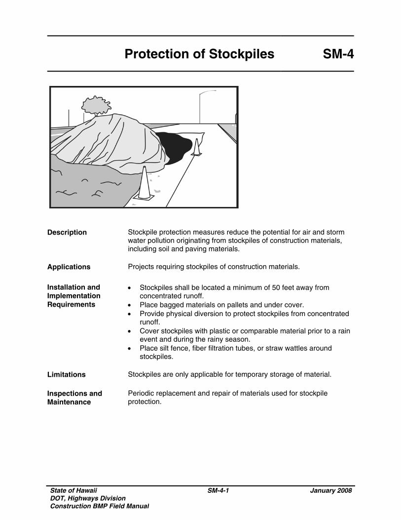
Description Stockpile protection measures reduce the potential for air and storm water pollution originating from stockpiles of construction materials, including soil and paving materials.
Applications Projects requiring stockpiles of construction materials.
Installation and Implementation Requirements
• Stockpiles shall be located a minimum of 50 feet away from concentrated runoff.
• Place bagged materials on pallets and under cover. • Provide physical diversion to protect stockpiles from concentrated
runoff. • Cover stockpiles with plastic or comparable material prior to a rain
event and during the rainy season. • Place silt fence, fiber filtration tubes, or straw wattles around
stockpiles. Limitations Stockpiles are only applicable for temporary storage of material. Inspections and Maintenance
Periodic replacement and repair of materials used for stockpile protection.

State of Hawaii DOT, Highways Division Construction BMP Field Manual
SM-4-2 January 2008
THIS PAGE INTENTIONALLY LEFT BLANK
State of Hawaii DOT, Highways Division Construction BMP Field Manual
SM-5-1 January 2008
Concrete Waste Management SM-5
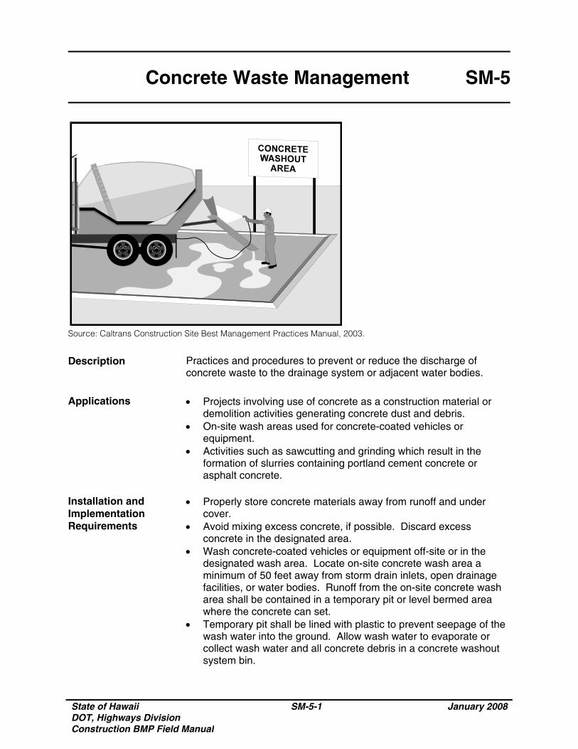
Source: Caltrans Construction Site Best Management Practices Manual, 2003.
Description Practices and procedures to prevent or reduce the discharge of concrete waste to the drainage system or adjacent water bodies.
Applications • Projects involving use of concrete as a construction material or
demolition activities generating concrete dust and debris. • On-site wash areas used for concrete-coated vehicles or
equipment. • Activities such as sawcutting and grinding which result in the
formation of slurries containing portland cement concrete or asphalt concrete.
Installation and Implementation Requirements
• Properly store concrete materials away from runoff and under cover.
• Avoid mixing excess concrete, if possible. Discard excess concrete in the designated area.
• Wash concrete-coated vehicles or equipment off-site or in the designated wash area. Locate on-site concrete wash area a minimum of 50 feet away from storm drain inlets, open drainage facilities, or water bodies. Runoff from the on-site concrete wash area shall be contained in a temporary pit or level bermed area where the concrete can set.
• Temporary pit shall be lined with plastic to prevent seepage of the wash water into the ground. Allow wash water to evaporate or collect wash water and all concrete debris in a concrete washout system bin.
State of Hawaii DOT, Highways Division Construction BMP Field Manual
SM-5-2 January 2008
Concrete Waste Management SM-5
Installation and Implementation Requirements (Continued)
• Break up and properly dispose of hardened concrete from wash area.
• Collect and properly dispose of aggregate concrete sweepings. • Provide concrete waste management training for employees and
contractors. Limitations Off-site concrete wash areas may be impracticable. Inspections and Maintenance
• Inspect concrete wash areas for damage and repair as necessary.• Regularly remove and dispose hardened concrete. • Monitor contractors to ensure proper concrete waste management
measures are implemented.
State of Hawaii, DOT, Highways Division Construction BMP Field Manual
January 2008
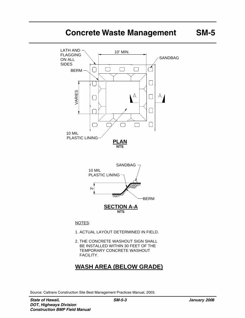
Concrete Waste Management SM-5
SM-5-3
WASH AREA (BELOW GRADE)
Source: Caltrans Construction Site Best Management Practices Manual, 2003.
LATH AND FLAGGING ON ALL SIDES
PLAN NTS
SECTION A-A NTS
BERM VA
RIE
S
10’ MIN. SANDBAG
10 MIL PLASTIC LINING
SANDBAG 10 MIL PLASTIC LINING
BERM
3’
NOTES: 1. ACTUAL LAYOUT DETERMINED IN FIELD. 2. THE CONCRETE WASHOUT SIGN SHALL BE INSTALLED WITHIN 30 FEET OF THE TEMPORARY CONCRETE WASHOUT FACILITY.
State of Hawaii, DOT, Highways Division Construction BMP Field Manual
January 2008
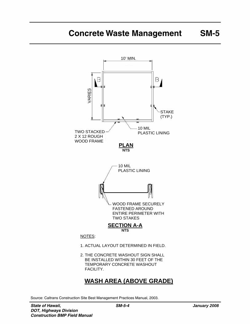
Concrete Waste Management SM-5
SM-5-4
WASH AREA (ABOVE GRADE)
Source: Caltrans Construction Site Best Management Practices Manual, 2003.
PLAN NTS
SECTION A-A NTS
VAR
IES
10’ MIN.
STAKE (TYP.)
10 MIL PLASTIC LINING
10 MIL PLASTIC LINING
WOOD FRAME SECURELY FASTENED AROUND ENTIRE PERIMETER WITH TWO STAKES
TWO STACKED 2 X 12 ROUGH WOOD FRAME
NOTES: 1. ACTUAL LAYOUT DETERMINED IN FIELD. 2. THE CONCRETE WASHOUT SIGN SHALL BE INSTALLED WITHIN 30 FEET OF THE TEMPORARY CONCRETE WASHOUT FACILITY.
State of Hawaii DOT, Highways Division Construction BMP Field Manual
SM-6-1 January 2008
Solid Waste Management SM-6
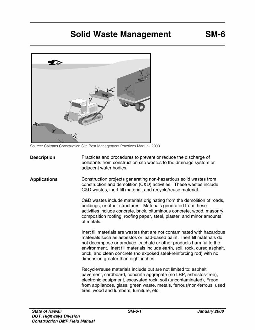
Source: Caltrans Construction Site Best Management Practices Manual, 2003.
Description Practices and procedures to prevent or reduce the discharge of pollutants from construction site wastes to the drainage system or adjacent water bodies.
Applications Construction projects generating non-hazardous solid wastes from
construction and demolition (C&D) activities. These wastes include C&D wastes, inert fill material, and recycle/reuse material. C&D wastes include materials originating from the demolition of roads, buildings, or other structures. Materials generated from these activities include concrete, brick, bituminous concrete, wood, masonry, composition roofing, roofing paper, steel, plaster, and minor amounts of metals. Inert fill materials are wastes that are not contaminated with hazardous materials such as asbestos or lead-based paint. Inert fill materials do not decompose or produce leachate or other products harmful to the environment. Inert fill materials include earth, soil, rock, cured asphalt, brick, and clean concrete (no exposed steel-reinforcing rod) with no dimension greater than eight inches. Recycle/reuse materials include but are not limited to: asphalt pavement, cardboard, concrete aggregate (no LBP, asbestos-free), electronic equipment, excavated rock, soil (uncontaminated), Freon from appliances, glass, green waste, metals, ferrous/non-ferrous, used tires, wood and lumbers, furniture, etc.
State of Hawaii DOT, Highways Division Construction BMP Field Manual
SM-6-2 January 2008
Solid Waste Management SM-6
Installation and Implementation Requirements
• Separate contaminated clean up materials from C&D wastes. Contamination may be from hazardous substances, friable asbestos, waste paint, solvents, sealers, or adhesives.
• Inert fill material shall not contain vegetation, organic material, or other solid waste.
• Inert fill materials shall not be mixed with other C&D waste. Limitations None Inspections and Maintenance
• Inspect construction waste and recycling areas regularly. • Schedule solid waste collection regularly. • Schedule recycling activities based on construction/demolition
phases.
State of Hawaii DOT, Highways Division Construction BMP Field Manual
SM-7-1 January 2008
Sanitary/Septic Waste Management
SM-7
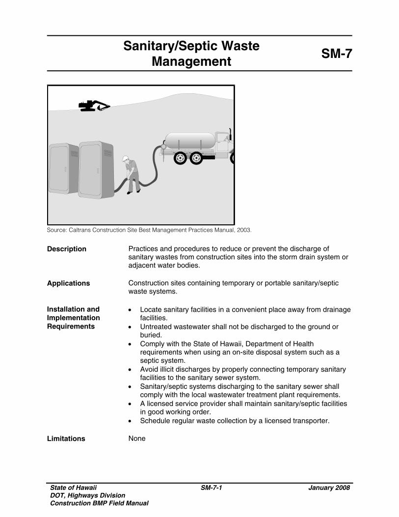
Source: Caltrans Construction Site Best Management Practices Manual, 2003.
Description Practices and procedures to reduce or prevent the discharge of sanitary wastes from construction sites into the storm drain system or adjacent water bodies.
Applications Construction sites containing temporary or portable sanitary/septic
waste systems. Installation and Implementation Requirements
• Locate sanitary facilities in a convenient place away from drainage facilities.
• Untreated wastewater shall not be discharged to the ground or buried.
• Comply with the State of Hawaii, Department of Health requirements when using an on-site disposal system such as a septic system.
• Avoid illicit discharges by properly connecting temporary sanitary facilities to the sanitary sewer system.
• Sanitary/septic systems discharging to the sanitary sewer shall comply with the local wastewater treatment plant requirements.
• A licensed service provider shall maintain sanitary/septic facilities in good working order.
• Schedule regular waste collection by a licensed transporter. Limitations None
State of Hawaii DOT, Highways Division Construction BMP Field Manual
SM-7-2 January 2008
Sanitary/Septic Waste Management
SM-7
Inspections and Maintenance
• Inspect and maintain facilities regularly. • Schedule regular waste collection. • Prevent illicit discharges.
State of Hawaii DOT, Highways Division Construction BMP Field Manual
SM-8-1 January 2008
Contaminated Soil Management
SM-8
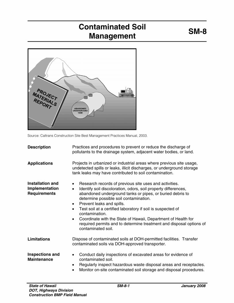
Source: Caltrans Construction Site Best Management Practices Manual, 2003.
Description Practices and procedures to prevent or reduce the discharge of pollutants to the drainage system, adjacent water bodies, or land.
Applications Projects in urbanized or industrial areas where previous site usage,
undetected spills or leaks, illicit discharges, or underground storage tank leaks may have contributed to soil contamination.
Installation and Implementation Requirements
• Research records of previous site uses and activities. • Identify soil discoloration, odors, soil property differences,
abandoned underground tanks or pipes, or buried debris to determine possible soil contamination.
• Prevent leaks and spills. • Test soil at a certified laboratory if soil is suspected of
contamination. • Coordinate with the State of Hawaii, Department of Health for
required permits and to determine treatment and disposal options of contaminated soil.
Limitations Dispose of contaminated soils at DOH-permitted facilities. Transfer
contaminated soils via DOH-approved transporter. Inspections and Maintenance
• Conduct daily inspections of excavated areas for evidence of contaminated soil.
• Regularly inspect hazardous waste disposal areas and receptacles.• Monitor on-site contaminated soil storage and disposal procedures.
State of Hawaii DOT, Highways Division Construction BMP Field Manual
SM-8-2 January 2008
Contaminated Soil Management
SM-8
Inspections and Maintenance (Continued)
• Prevent leaks and spills by implementing Spill Prevention and Control practices and procedures.
State of Hawaii DOT, Highways Division Construction BMP Field Manual
SM-9-1 January 2008
Hazardous Waste Management
SM-9
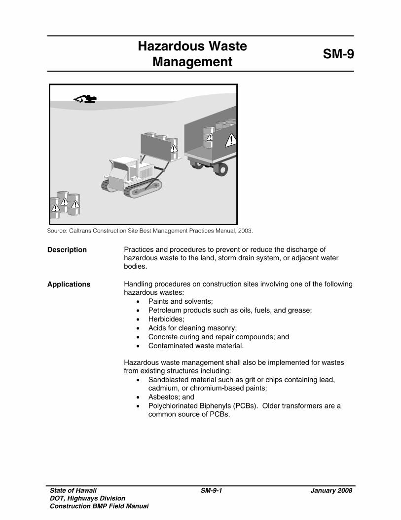
Source: Caltrans Construction Site Best Management Practices Manual, 2003.
Description Practices and procedures to prevent or reduce the discharge of hazardous waste to the land, storm drain system, or adjacent water bodies.
Applications Handling procedures on construction sites involving one of the following
hazardous wastes: • Paints and solvents; • Petroleum products such as oils, fuels, and grease; • Herbicides; • Acids for cleaning masonry; • Concrete curing and repair compounds; and • Contaminated waste material.
Hazardous waste management shall also be implemented for wastes from existing structures including:
• Sandblasted material such as grit or chips containing lead, cadmium, or chromium-based paints;
• Asbestos; and • Polychlorinated Biphenyls (PCBs). Older transformers are a
common source of PCBs.
State of Hawaii DOT, Highways Division Construction BMP Field Manual
SM-9-2 January 2008
Hazardous Waste Management
SM-9
Installation and Implementation Requirements
Recognize potentially hazardous waste by implementing the following: • Review product label and shipping papers; • Identify key words such as flammable or ignitable (able to catch
fire); carcinogenic (causes cancer); toxic or poisonous (injures or harms people or animals); and hazardous, danger, caustic or corrosive (burns through chemical action). Hawaii Administrative Rules (HAR) Title 11, Chapter 261 includes a list of hazardous waste and criteria;
• Review material safety data sheets (MSDS) from the manufacturer and supplier of the product; and
• Contact DOH, Hazardous Waste Program Office at 586-4226 for additional questions and information.
Material use practices and procedures for hazardous waste management include the following:
• Dispose container only after all of the product has been used; • Keep the original product label on the container since it includes
important safety and disposal information; • Restrict amount of herbicide prepared to quantity necessary for
the current application. Comply with the recommended usage instructions. Do not apply herbicides during or just before a rain event; and
• Remove as much paint from brushes on painted surface. Avoid cleaning or rinsing water-based paint brushes in soil, streets, gutters, storm drains, or streams. Rinse from water-based paints shall be discharged into the sanitary sewer system. Filter and re-use solvents and thinners. Dispose of oil-based paints and residue as a hazardous waste.
Waste recycling and disposal practices and procedures for hazardous waste management include the following:
• Designate areas for collection of hazardous wastes; • Store hazardous materials and wastes in covered containers; • Provide secondary containment for hazardous waste containers;• Keep wastes separate to prevent chemical reactions which
make recycling and disposal difficult; • Recycle useful materials such as oil or water-based paint; • Avoid disposal of toxic liquid wastes (solvents, used oils, and
paints) or chemicals (additives, acids, and curing compounds) in dumpsters allocated for construction debris;
• Schedule periodic waste collection to prevent overflow of containers; and
• Ensure collection, removal, and disposal of hazardous waste complies with regulations.
State of Hawaii DOT, Highways Division Construction BMP Field Manual
SM-9-3 January 2008
Hazardous Waste Management
SM-9
Installation and Implementation Requirements (Continued)
Hazardous waste management training shall include the following: • Awareness of potential dangers from hazardous wastes; • Identifying hazardous wastes; • Proper hazardous waste storage and disposal procedures; • Safety procedures for hazardous wastes; • Placement of warning signs in areas recently treated with
chemicals; • Use of cleanup materials for spills;
Limitations Hazardous waste that cannot be reused or recycled shall be disposed
of by a licensed hazardous waste hauler. Inspections and Maintenance
• Regularly inspect hazardous waste collection and storage areas and containers.
• Schedule hazardous waste collection regularly.

State of Hawaii DOT, Highways Division Construction BMP Field Manual
SM-9-4 January 2008
THIS PAGE INTENTIONALLY LEFT BLANK
State of Hawaii DOT, Highways Division Construction BMP Field Manual
SM-10-1 January 2008
Spill Prevention and Control SM-10
Source: Caltrans Construction Site Best Management Practices Manual, 2003.
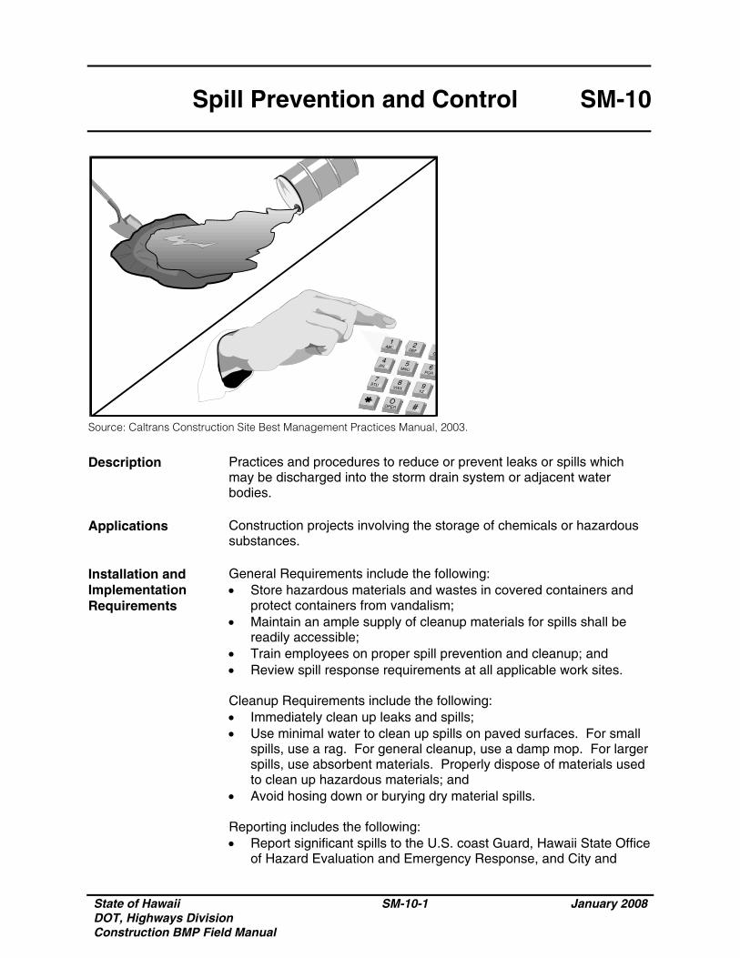
Description Practices and procedures to reduce or prevent leaks or spills which may be discharged into the storm drain system or adjacent water bodies.
Applications Construction projects involving the storage of chemicals or hazardous
substances. Installation and Implementation Requirements
General Requirements include the following: • Store hazardous materials and wastes in covered containers and
protect containers from vandalism; • Maintain an ample supply of cleanup materials for spills shall be
readily accessible; • Train employees on proper spill prevention and cleanup; and • Review spill response requirements at all applicable work sites. Cleanup Requirements include the following: • Immediately clean up leaks and spills; • Use minimal water to clean up spills on paved surfaces. For small
spills, use a rag. For general cleanup, use a damp mop. For larger spills, use absorbent materials. Properly dispose of materials used to clean up hazardous materials; and
• Avoid hosing down or burying dry material spills. Reporting includes the following: • Report significant spills to the U.S. coast Guard, Hawaii State Office
of Hazard Evaluation and Emergency Response, and City and
State of Hawaii DOT, Highways Division Construction BMP Field Manual
SM-10-2 January 2008
Spill Prevention and Control SM-10
Installation and Implementation Requirements (Continued)
County of Honolulu agencies, such as the Fire Department and • Per federal regulations, report significant spills of oil onto an
adjoining shoreline or into a water body to the National Response Center at 800-424-8802 (24 hour).
Vehicle and equipment maintenance activities requirements include the following: • Use a designated area and/or secondary containment for on-site
repair or maintenance activities. These areas shall be located awayfrom drainage courses;
• Complete regular inspections of on-site vehicles and equipment, including delivery trucks and employees’ vehicles, for leaks. Do not allow vehicles or equipment with leaks on-site;
• Secondary containment devices such as drop cloths and drain pans shall be used to catch leaks or spills while removing or changing fluids from vehicles or equipment;
• Place drip pans or absorbent materials under paving equipment not in use;
• Use absorbent materials on small spills. Avoid hosing down or burying spills. Remove and properly dispose of cleanup materials;
• Immediately transfer used fluids to the appropriate waste or recycling containers. Avoid leaving full drip pans and open containers on-site;
• Drain excess oil from oil filters prior to disposal by placing filter in a funnel over a waste oil recycling drum. Recycle oil filters if this service is available; and
• Store all cracked batteries in a non-leaking secondary container even if the acid appears to have drained out. Handle dropped batteries as cracked batteries until assured it is not leaking.
Vehicle and equipment fueling activities requirements include the following: • Use designated areas for required on-site fueling. Fueling areas
shall be located away from drainage courses; • Avoid “topping off” of fuel tanks; and • Use secondary containment devices such as drain pans to catch
spills or leaks while fueling. Limitations Use of a private spill cleanup company may be necessary. Inspections and Maintenance
• Update spill prevention and control plans and stock necessary cleanup materials as the chemicals used or stored on-site change.
• Ample supplies of materials for spill control and cleanup shall be located on-site near maintenance and material storage or unloading areas.
State of Hawaii DOT, Highways Division Construction BMP Field Manual
SM-11-1 January 2008
Vehicle and Equipment Cleaning
SM-11
Source: Caltrans Construction Site Best Management Practices Manual, 2003.
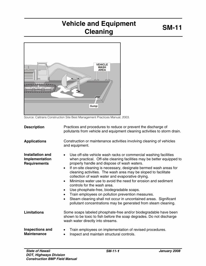
Description Practices and procedures to reduce or prevent the discharge of pollutants from vehicle and equipment cleaning activities to storm drain.
Applications Construction or maintenance activities involving cleaning of vehicles
and equipment. Installation and Implementation Requirements
• Use off-site vehicle wash racks or commercial washing facilities when practical. Off-site cleaning facilities may be better equipped to properly handle and dispose of wash waters.
• If on-site cleaning is necessary, designate bermed wash areas for cleaning activities. The wash area may be sloped to facilitate collection of wash water and evaporative drying.
• Minimize water use to avoid the need for erosion and sediment controls for the wash area.
• Use phosphate-free, biodegradable soaps. • Train employees on pollution prevention measures. • Steam cleaning shall not occur in uncontained areas. Significant
pollutant concentrations may be generated from steam cleaning. Limitations Some soaps labeled phosphate-free and/or biodegradable have been
shown to be toxic to fish before the soap degrades. Do not discharge wash water directly into streams.
Inspections and Maintenance
• Train employees on implementation of revised procedures. • Inspect and maintain structural controls.

State of Hawaii DOT, Highways Division Construction BMP Field Manual
SM-11-2 January 2008
THIS PAGE INTENTIONALLY LEFT BLANK
State of Hawaii DOT, Highways Division Construction BMP Field Manual
SM-12-1 January 2008
Vehicle and Equipment Maintenance
SM-12
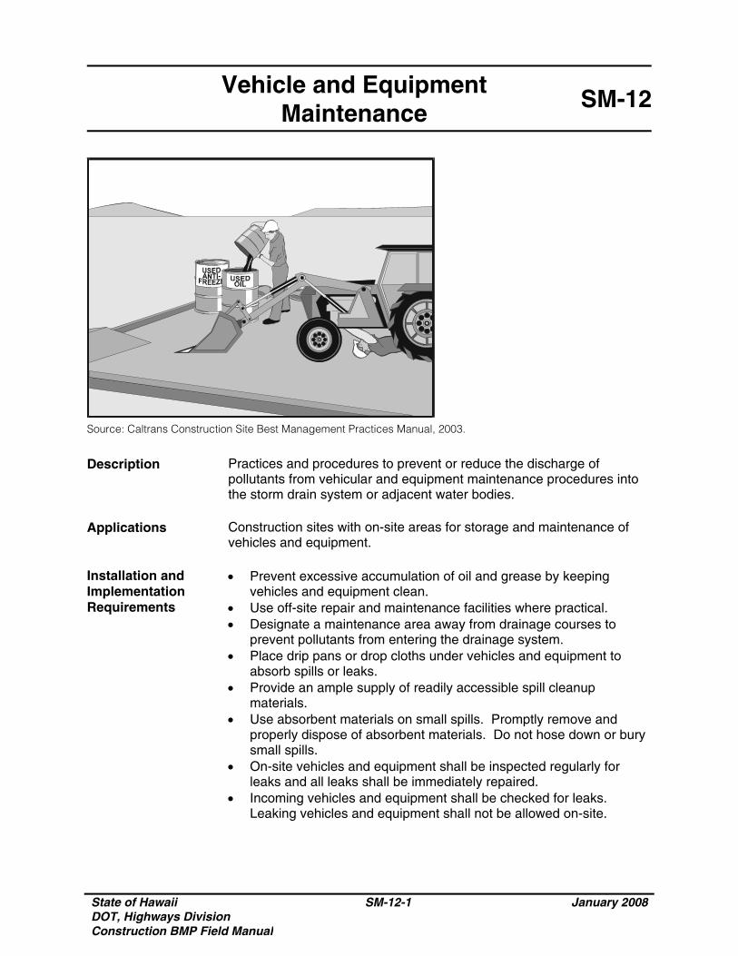
Source: Caltrans Construction Site Best Management Practices Manual, 2003.
Description Practices and procedures to prevent or reduce the discharge of pollutants from vehicular and equipment maintenance procedures into the storm drain system or adjacent water bodies.
Applications Construction sites with on-site areas for storage and maintenance of
vehicles and equipment. Installation and Implementation Requirements
• Prevent excessive accumulation of oil and grease by keeping vehicles and equipment clean.
• Use off-site repair and maintenance facilities where practical. • Designate a maintenance area away from drainage courses to
prevent pollutants from entering the drainage system. • Place drip pans or drop cloths under vehicles and equipment to
absorb spills or leaks. • Provide an ample supply of readily accessible spill cleanup
materials. • Use absorbent materials on small spills. Promptly remove and
properly dispose of absorbent materials. Do not hose down or bury small spills.
• On-site vehicles and equipment shall be inspected regularly for leaks and all leaks shall be immediately repaired.
• Incoming vehicles and equipment shall be checked for leaks. Leaking vehicles and equipment shall not be allowed on-site.
State of Hawaii DOT, Highways Division Construction BMP Field Manual
SM-12-2 January 2008
Vehicle and Equipment Maintenance
SM-12
Installation and Implementation Requirements (Continued)
• Segregate and recycle wastes from vehicle/equipment maintenance activities such as used oil or oil filters, greases, cleaning solutions, antifreeze, automotive batteries, and hydraulic and transmission fluids.
• Properly dispose of wastes generated by vehicle/equipment maintenance activities.
• Provide employee training on proper maintenance and spill cleanup practices and procedures.
Limitations Off-site maintenance facility may not be easily accessible. Inspections and Maintenance
• Regularly inspect vehicle and maintenance areas. • Ample supplies of spill cleanup materials shall be kept on-site.

State of Hawaii DOT, Highways Division Construction BMP Field Manual
SM-13-1 January 2008
Vehicle and Equipment Refueling
SM-13
Source: Caltrans Construction Site Best Management Practices Manual, 2003.
Description Practices and procedures to prevent or reduce the discharge of pollutants to storm water from vehicle and equipment fuel leaks or spills.
Applications Construction or maintenance activities involving fueling of vehicles or
equipment. Installation and Implementation Requirements
• Comply with Federal and State requirements regarding stationary, above ground storage tanks.
• Use off-site fueling sites when practical. Off-site fueling sites may be better equipped to service and handle spills due to multiple vehicles or pieces of equipment.
• If on-site fueling is necessary, locate designated fuel areas away from drainage courses to prevent contamination of storm water.
• Avoid “topping-off” of fuel tanks. • Drip pans or drop cloths shall be used to absorb leaks or spills
during fueling. • Absorbent spill cleanup materials shall be available and located in
fueling areas. • Use absorbent materials on small spills instead of hosing down or
burying the spill. Promptly remove and properly dispose the absorbent materials.
• Minimize mobile fueling of construction equipment by transporting equipment to designated areas for fueling.
• Train employees on proper fueling and cleanup procedures.
State of Hawaii DOT, Highways Division Construction BMP Field Manual
SM-13-2 January 2008
Vehicle and Equipment Refueling
SM-13
Limitations Off-site fueling of vehicles and equipment may not be practical. Inspections and Maintenance
• Ample supplies of materials for fuel spill control and cleanup shall be located on-site near fueling areas.
• Regularly inspect fueling areas and storage tanks.
State of Hawaii DOT, Highways Division Construction BMP Field Manual
SM-14-1 January 2008
Scheduling SM-14
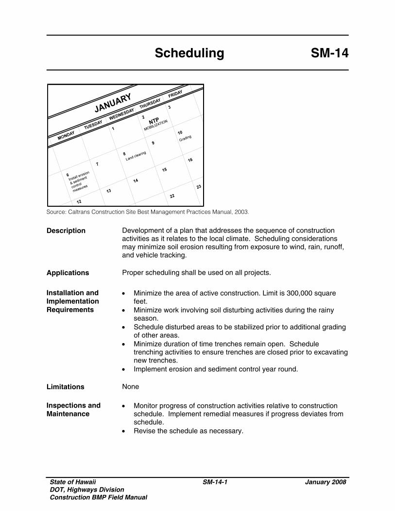
Source: Caltrans Construction Site Best Management Practices Manual, 2003.
Description Development of a plan that addresses the sequence of construction activities as it relates to the local climate. Scheduling considerations may minimize soil erosion resulting from exposure to wind, rain, runoff, and vehicle tracking.
Applications Proper scheduling shall be used on all projects.
Installation and Implementation Requirements
• Minimize the area of active construction. Limit is 300,000 square feet.
• Minimize work involving soil disturbing activities during the rainy season.
• Schedule disturbed areas to be stabilized prior to additional grading of other areas.
• Minimize duration of time trenches remain open. Schedule trenching activities to ensure trenches are closed prior to excavating new trenches.
• Implement erosion and sediment control year round. Limitations None Inspections and Maintenance
• Monitor progress of construction activities relative to construction schedule. Implement remedial measures if progress deviates from schedule.
• Revise the schedule as necessary.

State of Hawaii DOT, Highways Division Construction BMP Field Manual
SM-14-2 January 2008
THIS PAGE INTENTIONALLY LEFT BLANK
State of Hawaii DOT, Highways Division Construction BMP Field Manual
SM-15-1 January 2008
Location of PotentialSources of Sediment
SM-15
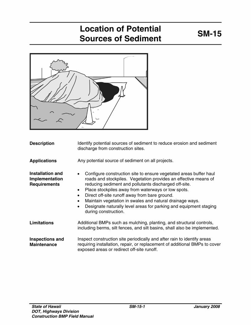
Description Identify potential sources of sediment to reduce erosion and sediment discharge from construction sites.
Applications Any potential source of sediment on all projects.
Installation and Implementation Requirements
• Configure construction site to ensure vegetated areas buffer haul roads and stockpiles. Vegetation provides an effective means of reducing sediment and pollutants discharged off-site.
• Place stockpiles away from waterways or low spots. • Direct off-site runoff away from bare ground. • Maintain vegetation in swales and natural drainage ways. • Designate naturally level areas for parking and equipment staging
during construction. Limitations Additional BMPs such as mulching, planting, and structural controls,
including berms, silt fences, and silt basins, shall also be implemented. Inspections and Maintenance
Inspect construction site periodically and after rain to identify areas requiring installation, repair, or replacement of additional BMPs to cover exposed areas or redirect off-site runoff.

State of Hawaii DOT, Highways Division Construction BMP Field Manual
SM-15-2 January 2008
THIS PAGE INTENTIONALLY LEFT BLANK
State of Hawaii DOT, Highways Division Construction BMP Field Manual
SM-16-1 January 2008
Preservation of Existing Vegetation
SM-16
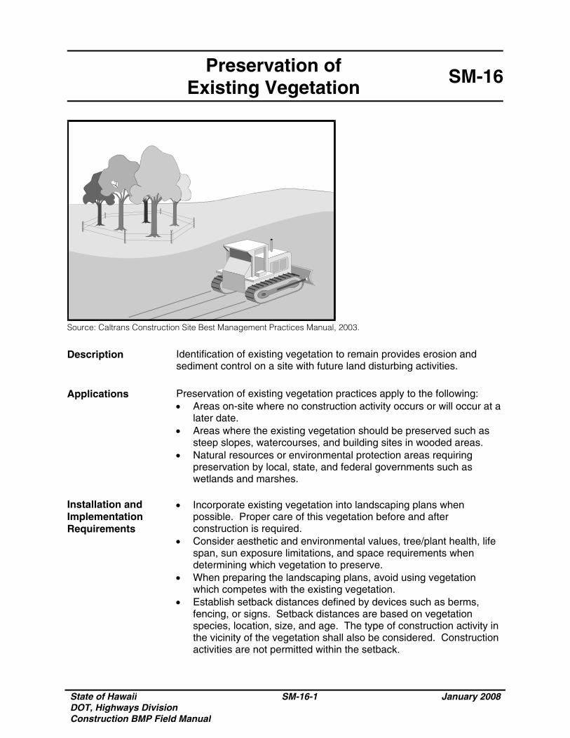
Source: Caltrans Construction Site Best Management Practices Manual, 2003.
Description Identification of existing vegetation to remain provides erosion and sediment control on a site with future land disturbing activities.
Applications Preservation of existing vegetation practices apply to the following:
• Areas on-site where no construction activity occurs or will occur at a later date.
• Areas where the existing vegetation should be preserved such as steep slopes, watercourses, and building sites in wooded areas.
• Natural resources or environmental protection areas requiring preservation by local, state, and federal governments such as wetlands and marshes.
Installation and Implementation Requirements
• Incorporate existing vegetation into landscaping plans when possible. Proper care of this vegetation before and after construction is required.
• Consider aesthetic and environmental values, tree/plant health, life span, sun exposure limitations, and space requirements when determining which vegetation to preserve.
• When preparing the landscaping plans, avoid using vegetation which competes with the existing vegetation.
• Establish setback distances defined by devices such as berms, fencing, or signs. Setback distances are based on vegetation species, location, size, and age. The type of construction activity in the vicinity of the vegetation shall also be considered. Construction activities are not permitted within the setback.
State of Hawaii DOT, Highways Division Construction BMP Field Manual
SM-16-2 January 2008
Preservation of Existing Vegetation
SM-16
Installation and Implementation Requirements (Continued)
• Protect existing vegetation using one of the following methods:
o Mark, flag, or fence areas of vegetation to be preserved; o Designate limits of root system (tree drip line); o Tree wells and retaining walls which are large enough to protect
the root system; o Limit grading to within one foot of the tree drip lines, if grading
under the tree is necessary; and o Locate construction traffic routes, spoil piles, etc. away from
existing vegetation. Limitations • Requires advanced planning and coordination between the owner/
developer, contractor, and designer. • Limited use if final site design does not incorporate existing
vegetation. • Diverse site topography may result in additional expenses to satisfy
vegetation preservation and the grading required for the site improvements.
Inspections and Maintenance
Inspect protective measures and immediately repair or replace damaged protection measures.
State of Hawaii DOT, Highways Division Construction BMP Field Manual
SM-17-1 January 2008
Dewatering Operations SM-17
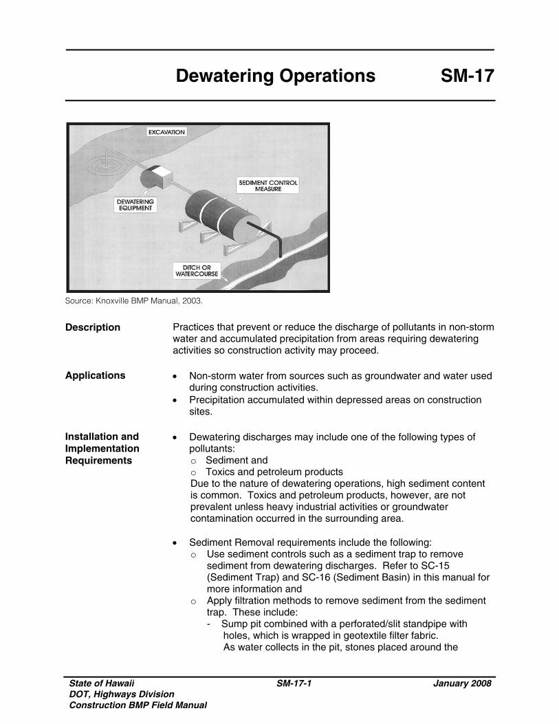
Source: Knoxville BMP Manual, 2003.
Description Practices that prevent or reduce the discharge of pollutants in non-storm water and accumulated precipitation from areas requiring dewatering activities so construction activity may proceed.
Applications • Non-storm water from sources such as groundwater and water used
during construction activities. • Precipitation accumulated within depressed areas on construction
sites. Installation and Implementation Requirements
• Dewatering discharges may include one of the following types of pollutants: o Sediment and o Toxics and petroleum products Due to the nature of dewatering operations, high sediment content is common. Toxics and petroleum products, however, are not prevalent unless heavy industrial activities or groundwater contamination occurred in the surrounding area.
• Sediment Removal requirements include the following:
o Use sediment controls such as a sediment trap to remove sediment from dewatering discharges. Refer to SC-15 (Sediment Trap) and SC-16 (Sediment Basin) in this manual for more information and
o Apply filtration methods to remove sediment from the sediment trap. These include: - Sump pit combined with a perforated/slit standpipe with
holes, which is wrapped in geotextile filter fabric. As water collects in the pit, stones placed around the
State of Hawaii DOT, Highways Division Construction BMP Field Manual
SM-17-2 January 2008
Dewatering Operations SM-17
Installation and Implementation Requirements (Continued)
standpipe filter the water, which collects in the pit prior to being pumped out. Due to the wrapped standpipe, an increased suction inlet area may be required to prevent clogging and unacceptable pump operation and
- Floating suction hose, which allows cleaner surface water to be pumped out.
• Toxics and Petroleum Products Removal requirements include the
following: o Areas of suspected groundwater contamination shall be tested
by a laboratory for known or suspected pollutants using methods detailed in 40 CFR Part 136. The laboratory shall enforce a quality assurance/quality control measures program. Comply with the dewatering requirements in subsection 209.03 (D) of the 2005 Standard Specifications, and as amended
o Discharges to the sanitary sewer system shall receive approval from DOH and the owner of the wastewater system. Additional testing and disposal requirements may be necessary.
Limitations Contaminated water may be an indication of contaminated soil. Refer to
SM-8 (Contaminated Soil Management) in this manual for more information.
Inspections and Maintenance
• Inspect excavated areas daily for contaminated water indicated by discoloration, oily sheen, or odors.
• Remove and properly dispose of sediment collected in sediment control devices.
• Inspect the dewatering discharge point for erosion daily.
State of Hawaii DOT, Highways Division Construction BMP Field Manual
SM-18-1 January 2008
Dust Control SM-18
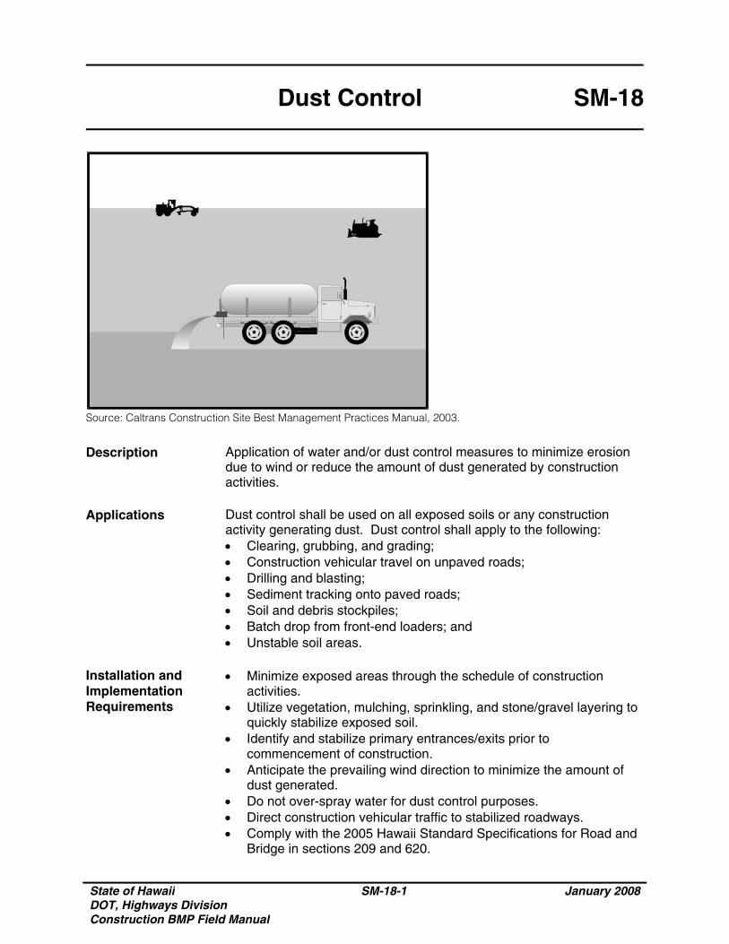
Source: Caltrans Construction Site Best Management Practices Manual, 2003.
Description Application of water and/or dust control measures to minimize erosion due to wind or reduce the amount of dust generated by construction activities.
Applications Dust control shall be used on all exposed soils or any construction
activity generating dust. Dust control shall apply to the following: • Clearing, grubbing, and grading; • Construction vehicular travel on unpaved roads; • Drilling and blasting; • Sediment tracking onto paved roads; • Soil and debris stockpiles; • Batch drop from front-end loaders; and • Unstable soil areas.
Installation and Implementation Requirements
• Minimize exposed areas through the schedule of construction activities.
• Utilize vegetation, mulching, sprinkling, and stone/gravel layering to quickly stabilize exposed soil.
• Identify and stabilize primary entrances/exits prior to commencement of construction.
• Anticipate the prevailing wind direction to minimize the amount of dust generated.
• Do not over-spray water for dust control purposes. • Direct construction vehicular traffic to stabilized roadways. • Comply with the 2005 Hawaii Standard Specifications for Road and
Bridge in sections 209 and 620.
State of Hawaii DOT, Highways Division Construction BMP Field Manual
SM-18-2 January 2008
Dust Control SM-18
Limitations • Daily or more frequent applications of water may be necessary
since water is a short-term dust preventative. • Erosion may result from overwatering. • Oil may not be used for dust control since the oil may discharge into
a drainageway or seep into soil. • Some dust suppression chemicals may cause soil to be water
repellent resulting in increased runoff. Inspections and Maintenance
Inspect construction site periodically and after rain to identify areas requiring installation, repair, or replacement of additional BMPs to cover bare ground or redirect off-site runoff.
State of Hawaii DOT, Highways Division Construction BMP Field Manual
SM-19-1 January 2008
Paving Operations SM-19
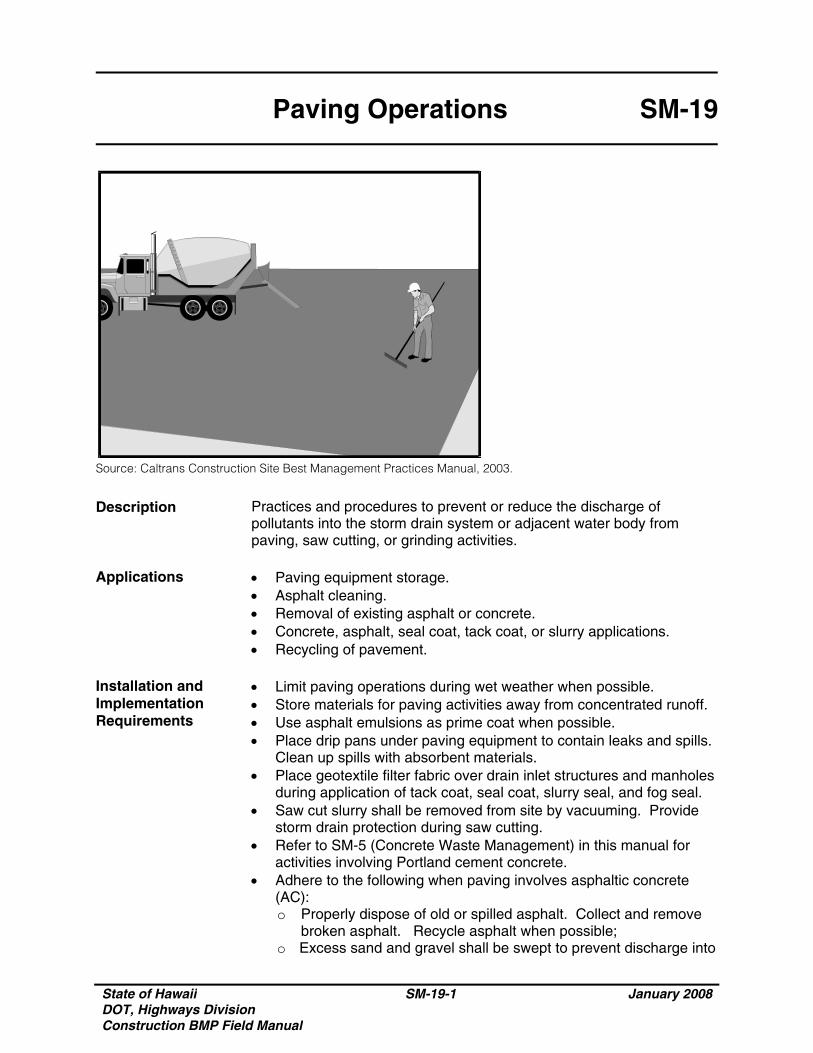
Source: Caltrans Construction Site Best Management Practices Manual, 2003.
Description Practices and procedures to prevent or reduce the discharge of pollutants into the storm drain system or adjacent water body from paving, saw cutting, or grinding activities.
Applications • Paving equipment storage.
• Asphalt cleaning. • Removal of existing asphalt or concrete. • Concrete, asphalt, seal coat, tack coat, or slurry applications. • Recycling of pavement.
Installation and Implementation Requirements
• Limit paving operations during wet weather when possible. • Store materials for paving activities away from concentrated runoff. • Use asphalt emulsions as prime coat when possible. • Place drip pans under paving equipment to contain leaks and spills.
Clean up spills with absorbent materials. • Place geotextile filter fabric over drain inlet structures and manholes
during application of tack coat, seal coat, slurry seal, and fog seal. • Saw cut slurry shall be removed from site by vacuuming. Provide
storm drain protection during saw cutting. • Refer to SM-5 (Concrete Waste Management) in this manual for
activities involving Portland cement concrete. • Adhere to the following when paving involves asphaltic concrete
(AC): o Properly dispose of old or spilled asphalt. Collect and remove
broken asphalt. Recycle asphalt when possible; o Excess sand and gravel shall be swept to prevent discharge into
State of Hawaii DOT, Highways Division Construction BMP Field Manual
SM-19-2 January 2008
Paving Operations SM-19
Installation and Implementation Requirements (Continued)
the storm drainage system or adjacent water body; and o Comply with storm water permitting requirements for industrial
activities if paving requires an on-site mixing plant.
Limitations Restrict paving operations during wet weather to prevent contact
between storm water and paving materials. Inspections and Maintenance
• Ample supplies of drip pans and absorbent materials shall be kept on-site.
• Inspect inlet protection equipment. • Monitor employees to ensure appropriate paving practices and
procedures are being implemented.
State of Hawaii DOT, Highways Division Construction BMP Field Manual
SM-20-1 January 2008
Structure Construction and Painting
SM-20
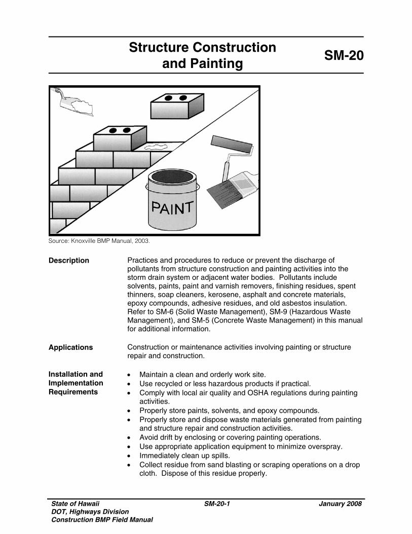
Source: Knoxville BMP Manual, 2003.
Description Practices and procedures to reduce or prevent the discharge of pollutants from structure construction and painting activities into the storm drain system or adjacent water bodies. Pollutants include solvents, paints, paint and varnish removers, finishing residues, spent thinners, soap cleaners, kerosene, asphalt and concrete materials, epoxy compounds, adhesive residues, and old asbestos insulation. Refer to SM-6 (Solid Waste Management), SM-9 (Hazardous Waste Management), and SM-5 (Concrete Waste Management) in this manual for additional information.
Applications Construction or maintenance activities involving painting or structure
repair and construction. Installation and Implementation Requirements
• Maintain a clean and orderly work site. • Use recycled or less hazardous products if practical. • Comply with local air quality and OSHA regulations during painting
activities. • Properly store paints, solvents, and epoxy compounds. • Properly store and dispose waste materials generated from painting
and structure repair and construction activities. • Avoid drift by enclosing or covering painting operations. • Use appropriate application equipment to minimize overspray. • Immediately clean up spills. • Collect residue from sand blasting or scraping operations on a drop
cloth. Dispose of this residue properly.
State of Hawaii DOT, Highways Division Construction BMP Field Manual
SM-20-2 January 2008
Structure Construction and Painting
SM-20
Installation and Implementation Requirements (Continued)
• Paint chips containing lead or tributyl tin shall be treated as hazardous waste. Refer to the SM-9 (Hazardous Waste Management) in this manual for more information.
• Clean painting equipment in a sink connected to the sanitary sewer system.
• Mix paints in a covered and contained area when possible to minimize adverse impacts from spills.
• Comply with applicable laws and regulations for recycle/disposal of residual paints, solvents, lumber, and other materials.
• Minimize inadvertent disposal of residual paints and other liquids by ensuring nearby storm drains are clearly marked.
• Upon completion of the activity, inspect the storm drain system in the immediate work area and remove dirt or debris.
• Provide employee training. • Properly dispose of material from sand blasting activities. Chips
and dust from marine paints or paints containing lead shall be considered hazardous waste. Paint chips and dust from non-hazardous dry stripping and sand blasting shall be swept and disposed of as trash.
Limitations • Availability of recycled or less hazardous products may be limited.
• Hazardous waste which may not be recycled or reused shall be disposed of by a licensed hazardous waste transporter.
• Storm water quality protection measures shall comply with State and Federal safety (OSHA) and air quality regulations.
Inspections and Maintenance
Materials and equipment for proper housekeeping and disposal practices shall be readily available.
State of Hawaii DOT, Highways Division Construction BMP Field Manual
SM-21-1 January 2008
Topsoil Management SM-21
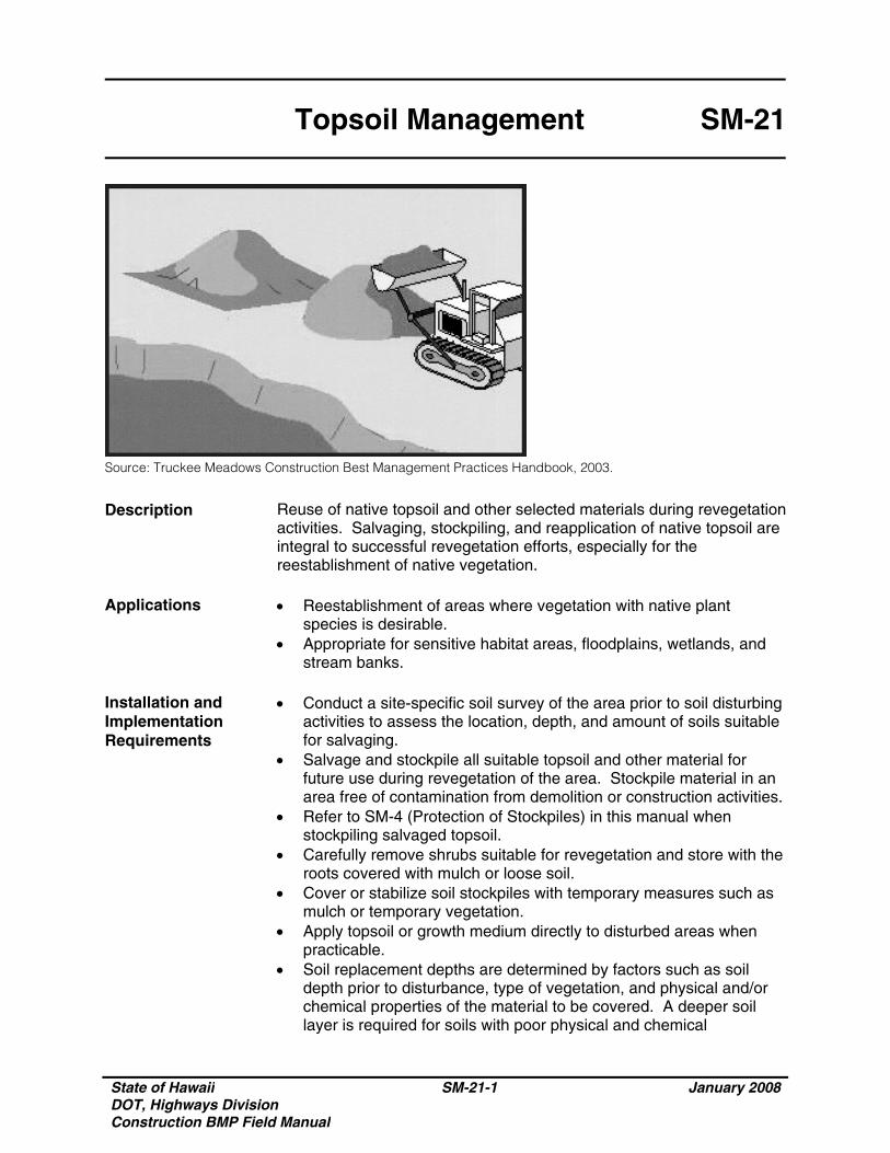
Source: Truckee Meadows Construction Best Management Practices Handbook, 2003.
Description Reuse of native topsoil and other selected materials during revegetation activities. Salvaging, stockpiling, and reapplication of native topsoil are integral to successful revegetation efforts, especially for the reestablishment of native vegetation.
Applications • Reestablishment of areas where vegetation with native plant
species is desirable. • Appropriate for sensitive habitat areas, floodplains, wetlands, and
stream banks. Installation and Implementation Requirements
• Conduct a site-specific soil survey of the area prior to soil disturbing activities to assess the location, depth, and amount of soils suitable for salvaging.
• Salvage and stockpile all suitable topsoil and other material for future use during revegetation of the area. Stockpile material in an area free of contamination from demolition or construction activities.
• Refer to SM-4 (Protection of Stockpiles) in this manual when stockpiling salvaged topsoil.
• Carefully remove shrubs suitable for revegetation and store with the roots covered with mulch or loose soil.
• Cover or stabilize soil stockpiles with temporary measures such as mulch or temporary vegetation.
• Apply topsoil or growth medium directly to disturbed areas when practicable.
• Soil replacement depths are determined by factors such as soil depth prior to disturbance, type of vegetation, and physical and/or chemical properties of the material to be covered. A deeper soil layer is required for soils with poor physical and chemical
State of Hawaii DOT, Highways Division Construction BMP Field Manual
SM-21-2 January 2008
Topsoil Management SM-21
Installation and Implementation Requirements (Continued)
properties. Testing (nutrients, pH, and toxicity factors) of replacement soils and material to be covered shall be completed prior to reapplication.
• Consideration of the following items is necessary when developing a topsoil management plan: o Quality and amount of native topsoil or growth medium; o Area of surface disturbance to which topsoil or growth medium
will be applied and the required depth of application; o Methodology for salvaging topsoil or growth medium; o Stockpile location, duration of storage, and required erosion
control measures to protect stockpile; o Feasibility of direct application of salvaged soils; and o Availability of other growth media to supplement topsoil
reclamation. Limitations • Stockpiles may limit the area available for construction activity.
• Runoff from stockpiles may adversely impact water quality. Inspections and Maintenance
• Regularly inspect stockpiles for erosion and stabilize as necessary. • Inspect stockpile covers to ensure adequate protection from wind
and rain. • Adequately water plantings until they are established.
State of Hawaii DOT, Highways Division Construction BMP Field Manual
EC January 2008
Chapter 2 Erosion Control
Erosion Control (EC) BMPs are devices installed on a construction site that reduce the erosion potential as a result of land disturbing activities. Erosion Control BMPs serve as prevention measures by stabilizing soil. They are the primary measures of reducing the negative impact of construction activities by preventing storm water pollution. In this chapter:
Control construction activities; Stabilize soil; Minimize disturbed area and protect
natural vegetations, streams and soil; Control storm water flowing onto and
through the project; Protect slopes.

State of Hawaii DOT, Highways Division Construction BMP Field Manual
EC January 2008
THIS PAGE INTENTIONALLY LEFT BLANK
State of Hawaii DOT, Highways Division Construction BMP Field Manual
EC-1-1 January 2008
Construction Road Stabilization EC-1
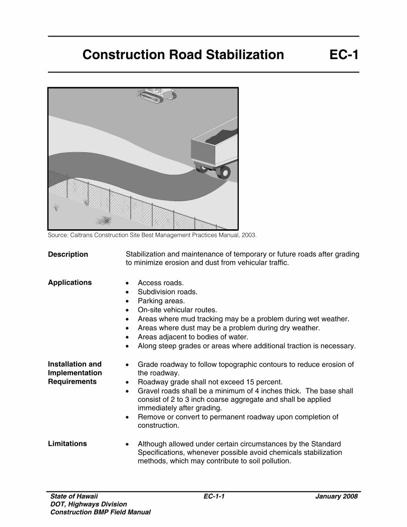
Source: Caltrans Construction Site Best Management Practices Manual, 2003.
Description Stabilization and maintenance of temporary or future roads after grading to minimize erosion and dust from vehicular traffic.
Applications • Access roads.
• Subdivision roads. • Parking areas. • On-site vehicular routes. • Areas where mud tracking may be a problem during wet weather. • Areas where dust may be a problem during dry weather. • Areas adjacent to bodies of water. • Along steep grades or areas where additional traction is necessary.
Installation and Implementation Requirements
• Grade roadway to follow topographic contours to reduce erosion of the roadway.
• Roadway grade shall not exceed 15 percent. • Gravel roads shall be a minimum of 4 inches thick. The base shall
consist of 2 to 3 inch coarse aggregate and shall be applied immediately after grading.
• Remove or convert to permanent roadway upon completion of construction.
Limitations
• Although allowed under certain circumstances by the Standard Specifications, whenever possible avoid chemicals stabilization methods, which may contribute to soil pollution.
State of Hawaii DOT, Highways Division Construction BMP Field Manual
EC-1-2 January 2008
Construction Road Stabilization EC-1
Limitations (Continued)
• Construction traffic management may be subject to air quality control measures. Contact the local air quality management agency for more information.
Inspections and Maintenance
• Properly maintain all BMP features. Inspect, prepare a written report, and make repairs to BMP measures at following intervals: (1) Inspect weekly during dry periods. (2) Within 24 hours of any rainfall of 0.5 inch or greater which occurs
in a 24-hour periods. (3) Daily during periods of prolonged rainfall. (4) When existing erosion control measures are damaged or not
operating properly as required by site specific BMP. • Periodically apply additional aggregate on gravel roads. • During the dry season, active dirt construction roads shall be
watered three or more times per day.
State of Hawaii DOT, Highways Division Construction BMP Field Manual
EC-2-1 January 2008
Stabilized Construction Entrance/Exit
EC-2
Source: Caltrans Construction Site Best Management Practices Manual, 2003.
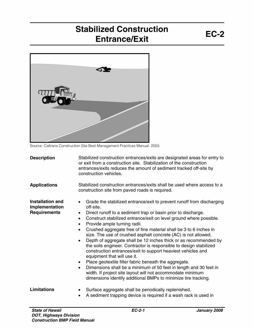
Description Stabilized construction entrances/exits are designated areas for entry to or exit from a construction site. Stabilization of the construction entrances/exits reduces the amount of sediment tracked off-site by construction vehicles.
Applications Stabilized construction entrances/exits shall be used where access to a
construction site from paved roads is required. Installation and Implementation Requirements
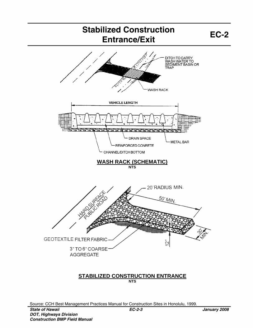
• Grade the stabilized entrance/exit to prevent runoff from discharging off-site.
• Direct runoff to a sediment trap or basin prior to discharge. • Construct stabilized entrance/exit on level ground where possible. • Provide ample turning radii. • Crushed aggregate free of fine material shall be 3 to 6 inches in
size. The use of crushed asphalt concrete (AC) is not allowed. • Depth of aggregate shall be 12 inches thick or as recommended by
the soils engineer. Contractor is responsible to design stabilized construction entrances/exit to support heaviest vehicles and equipment that will use it.
• Place geotextile filter fabric beneath the aggregate. • Dimensions shall be a minimum of 50 feet in length and 30 feet in
width. If project site layout will not accommodate minimum dimensions identify additional BMPs to minimize tire tracking.
Limitations
• Surface aggregate shall be periodically replenished. • A sediment trapping device is required if a wash rack is used in
State of Hawaii DOT, Highways Division Construction BMP Field Manual
EC-2-2 January 2008
Stabilized Construction Entrance/Exit
EC-2
Limitations (Continued)
conjunction with the stabilized construction entrance/exit. • If the construction entrance is not preventing sediment from being
tracked onto the pavement, then alternative measures to keep the streets free of sediment shall be used. This may include street sweeping, and increasing the dimensions of the entrance, or the installation of a wheel wash. Any sediment that is tracked onto the pavement shall be removed by shoveling or street sweeping. The sediment collected by sweeping shall be removed or stabilized on site. The pavement shall not be cleaned by washing down the street, except when sweeping is ineffective and there is a threat to public safety. If it is necessary to wash the streets, the construction of a small sump shall be considered. The sediment would then be washed into the sump where it can be controlled. Use BMPs for adjacent drainage structures.
Inspections and Maintenance
• Inspect construction entrance/exit weekly during dry periods as well as within 24 hours of any rainfall of 0.5 inch or greater which occurs in a 24-hour period and daily during periods of prolonged rainfall for damage.
• Remove deposited sediment from adjacent roadways or paved areas within 24 hours.
• Replenish surface aggregate periodically. • Upon project completion, all construction entrances/exits shall be
removed by the contractor and restore the area to the condition approved by the Engineer.
Stabilized Construction
Entrance/Exit EC-2
Source: CCH Best Management Practices Manual for Construction Sites in Honolulu, 1999. State of Hawaii DOT, Highways Division Construction BMP Field Manual
EC-2-3 January 2008
WASH RACK (SCHEMATIC) NTS
STABILIZED CONSTRUCTION ENTRANCE NTS

State of Hawaii DOT, Highways Division Construction BMP Field Manual
EC-2-4 January 2008
THIS PAGE INTENTIONALLY LEFT BLANK
State of Hawaii DOT, Highways Division Construction BMP Field Manual
EC-3-1 January 2008
Temporary Stream Crossing EC-3
Source: Truckee Meadows Construction Site Best Management Practices Handbook, 2003.
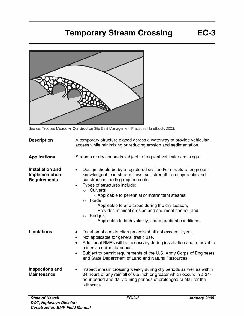
Description A temporary structure placed across a waterway to provide vehicular access while minimizing or reducing erosion and sedimentation.
Applications Streams or dry channels subject to frequent vehicular crossings.
Installation and Implementation Requirements
• Design should be by a registered civil and/or structural engineer knowledgeable in stream flows, soil strength, and hydraulic and construction loading requirements.
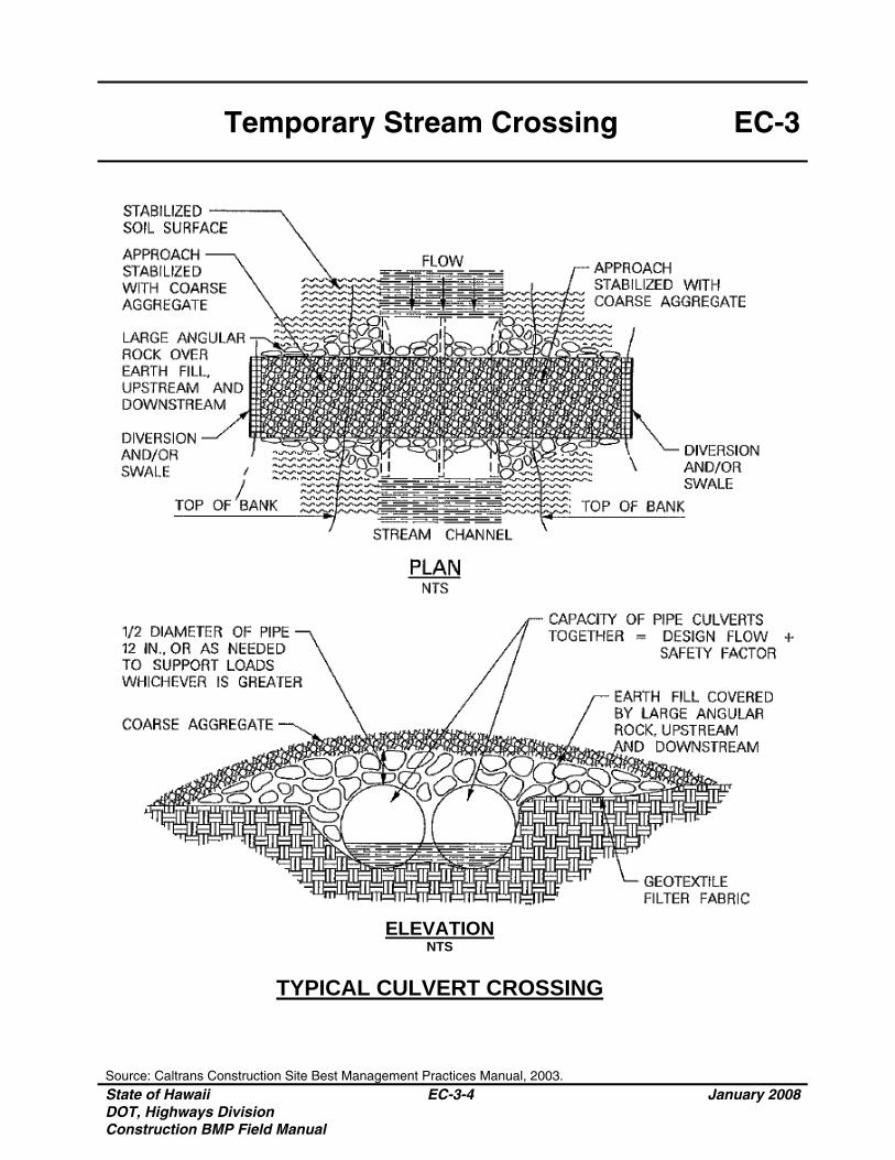
• Types of structures include: o Culverts
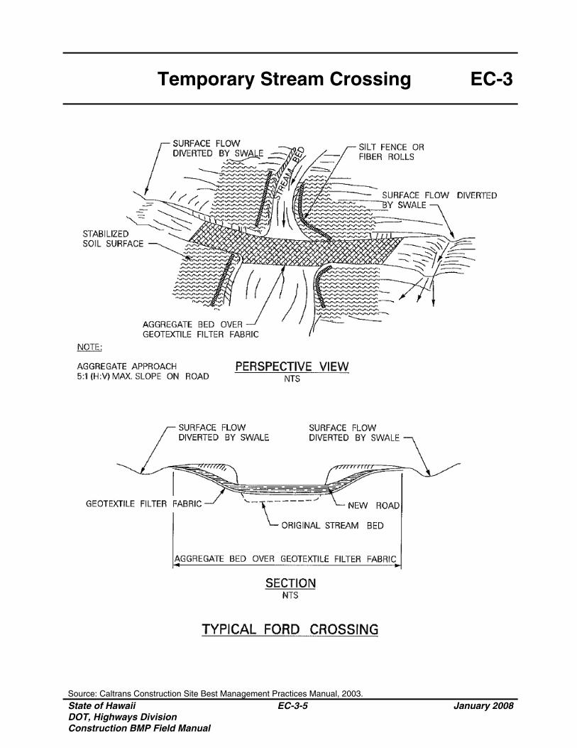
- Applicable to perennial or intermittent steams; o Fords
- Applicable to arid areas during the dry season, - Provides minimal erosion and sediment control; and
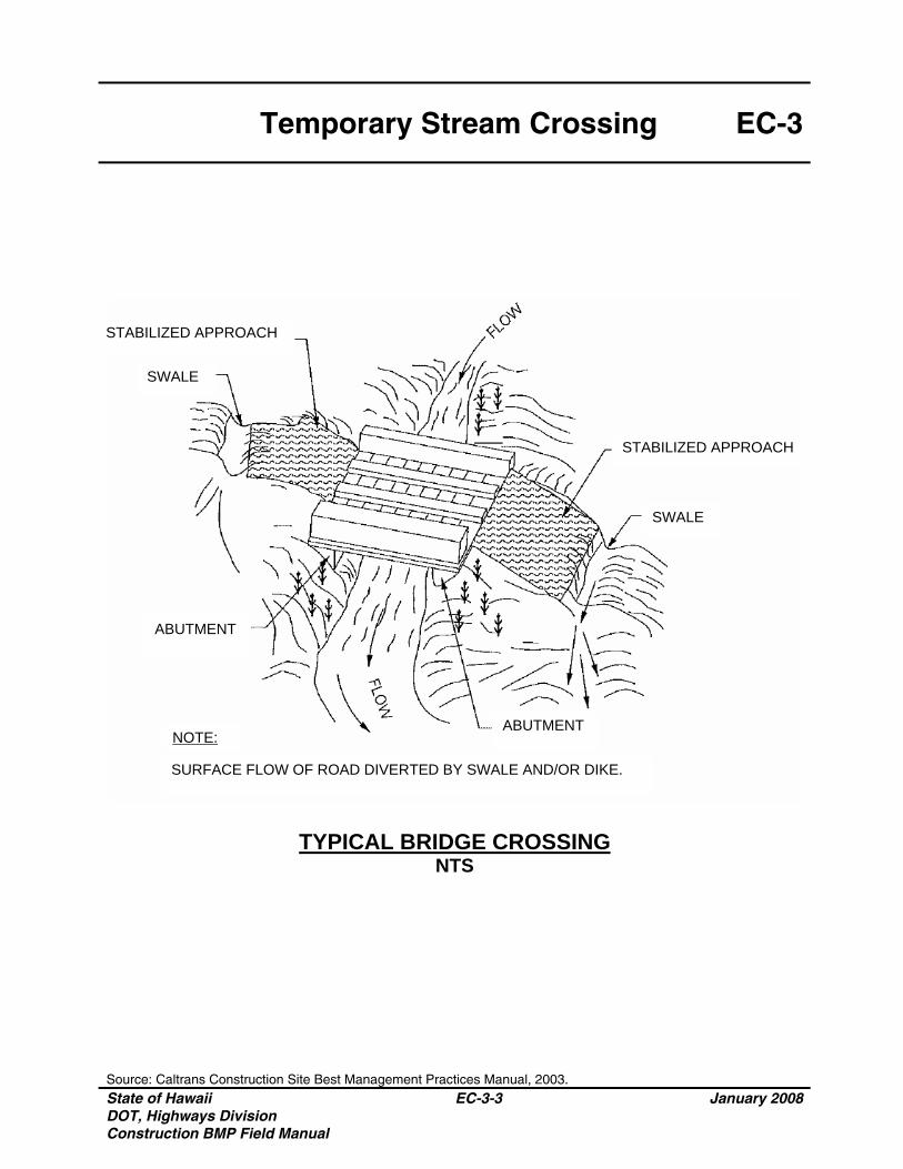
o Bridges - Applicable to high velocity, steep gradient conditions.
Limitations • Duration of construction projects shall not exceed 1 year.
• Not applicable for general traffic use. • Additional BMPs will be necessary during installation and removal to
minimize soil disturbance. • Subject to permit requirements of the U.S. Army Corps of Engineers
and State Department of Land and Natural Resources. Inspections and Maintenance
• Inspect stream crossing weekly during dry periods as well as within 24 hours of any rainfall of 0.5 inch or greater which occurs in a 24-hour period and daily during periods of prolonged rainfall for the following:
State of Hawaii DOT, Highways Division Construction BMP Field Manual
EC-3-2 January 2008
Temporary Stream Crossing EC-3
Inspections and Maintenance (Continued)
o Blockage in channels; o Debris accumulation in culverts, behind fords, or under bridges;o Abutment erosion, rip-rap displacement, channel scour, and
piping in soil; and o Visible signs of structural degradation.
• Remove silt and debris periodically. • Replenish aggregate from culvert inlets and outlets as necessary.
Temporary Stream Crossing EC-3
TYPICAL BRIDGE CROSSING
NTS
Source: Caltrans Construction Site Best Management Practices Manual, 2003. State of Hawaii DOT, Highways Division Construction BMP Field Manual
EC-3-3 January 2008
NOTE:
SURFACE FLOW OF ROAD DIVERTED BY SWALE AND/OR DIKE.
ABUTMENT
SWALE
SWALE
ABUTMENT
STABILIZED APPROACH
STABILIZED APPROACH
Temporary Stream Crossing EC-3
Source: Caltrans Construction Site Best Management Practices Manual, 2003. State of Hawaii DOT, Highways Division Construction BMP Field Manual
EC-3-4 January 2008
PLAN NTS
ELEVATION NTS
TYPICAL CULVERT CROSSING
Temporary Stream Crossing EC-3
Source: Caltrans Construction Site Best Management Practices Manual, 2003. State of Hawaii DOT, Highways Division Construction BMP Field Manual
EC-3-5 January 2008
PERSPECTIVE VIEW NTS
NOTE: AGGREGATE APPROACH 5:1 (H:V) MAX. SLOPE ON ROAD
SECTION NTS
TYPICAL FORD CROSSING

State of Hawaii DOT, Highways Division Construction BMP Field Manual
EC-3-6 January 2008
THIS PAGE INTENTIONALLY LEFT BLANK
State of Hawaii DOT, Highways Division Construction BMP Field Manual
EC-4-1 January 2008
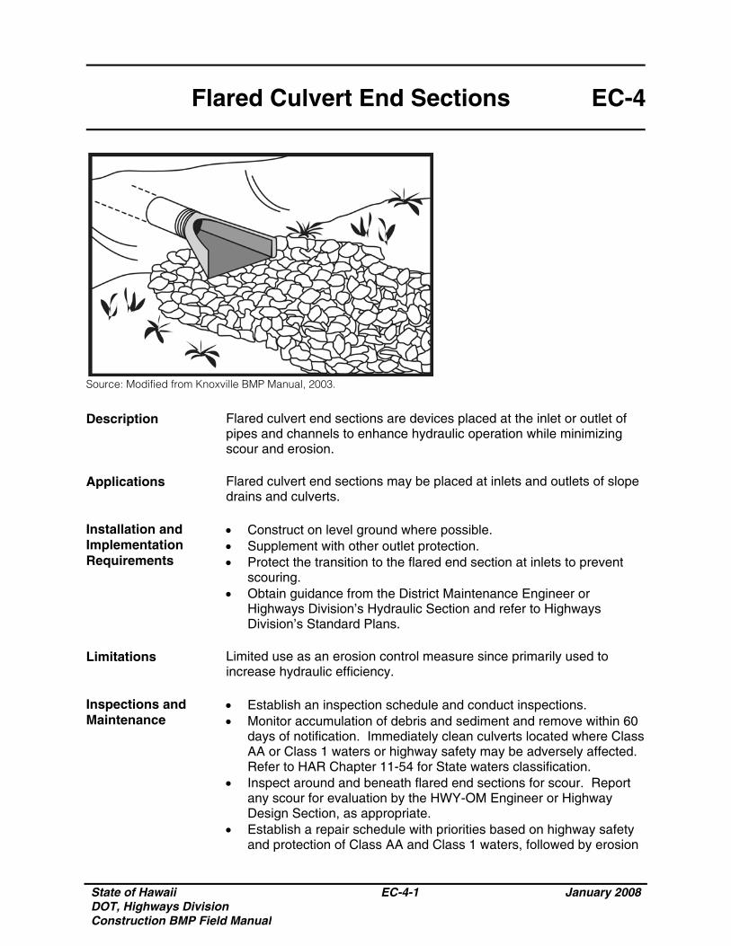
Flared Culvert End Sections EC-4
Source: Modified from Knoxville BMP Manual, 2003.
Description Flared culvert end sections are devices placed at the inlet or outlet of pipes and channels to enhance hydraulic operation while minimizing scour and erosion.
Applications Flared culvert end sections may be placed at inlets and outlets of slope
drains and culverts. Installation and Implementation Requirements
• Construct on level ground where possible. • Supplement with other outlet protection. • Protect the transition to the flared end section at inlets to prevent
scouring. • Obtain guidance from the District Maintenance Engineer or
Highways Division’s Hydraulic Section and refer to Highways Division’s Standard Plans.
Limitations Limited use as an erosion control measure since primarily used to
increase hydraulic efficiency. Inspections and Maintenance
• Establish an inspection schedule and conduct inspections. • Monitor accumulation of debris and sediment and remove within 60
days of notification. Immediately clean culverts located where Class AA or Class 1 waters or highway safety may be adversely affected. Refer to HAR Chapter 11-54 for State waters classification.
• Inspect around and beneath flared end sections for scour. Report any scour for evaluation by the HWY-OM Engineer or Highway Design Section, as appropriate.
• Establish a repair schedule with priorities based on highway safety and protection of Class AA and Class 1 waters, followed by erosion
State of Hawaii DOT, Highways Division Construction BMP Field Manual
EC-4-2 January 2008
Flared Culvert End Sections EC-4
Inspections and Maintenance (Continued)
potential and possible damage to down-slope areas.
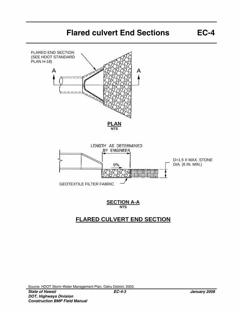
Flared culvert End Sections EC-4
Source: HDOT Storm Water Management Plan, Oahu District, 2003. State of Hawaii DOT, Highways Division Construction BMP Field Manual
EC-4-3 January 2008
PLAN NTS
GEOTEXTILE FILTER FABRIC
FLARED END SECTION (SEE HDOT STANDARD PLAN H-18)
SECTION A-A
NTS
FLARED CULVERT END SECTION
D=1.5 X MAX. STONE DIA. (6 IN. MIN.)

State of Hawaii DOT, Highways Division Construction BMP Field Manual
EC-4-4 January 2008
THIS PAGE INTENTIONALLY LEFT BLANK
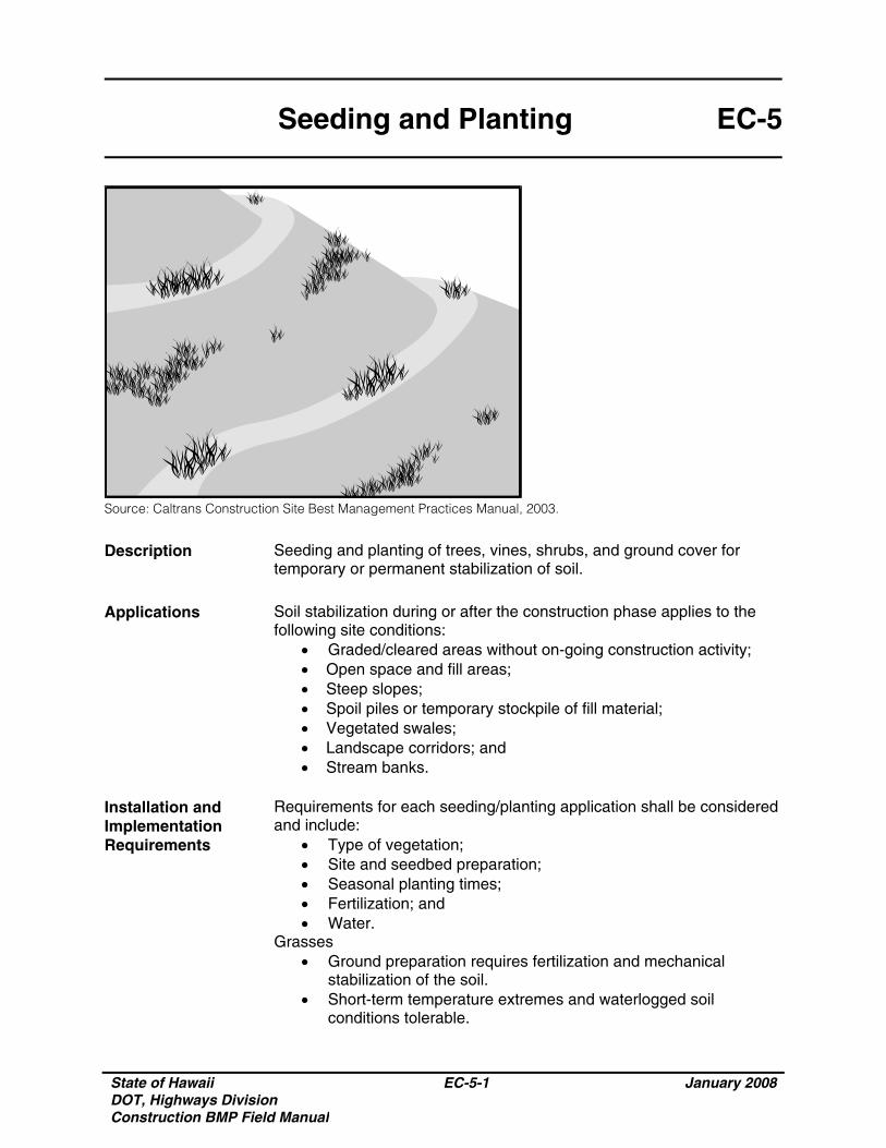
State of Hawaii DOT, Highways Division Construction BMP Field Manual
EC-5-1 January 2008
Seeding and Planting EC-5
Source: Caltrans Construction Site Best Management Practices Manual, 2003.
Description Seeding and planting of trees, vines, shrubs, and ground cover for temporary or permanent stabilization of soil.
Applications Soil stabilization during or after the construction phase applies to the
following site conditions: • Graded/cleared areas without on-going construction activity; • Open space and fill areas; • Steep slopes; • Spoil piles or temporary stockpile of fill material; • Vegetated swales; • Landscape corridors; and • Stream banks.
Installation and Implementation Requirements
Requirements for each seeding/planting application shall be considered and include:
• Type of vegetation; • Site and seedbed preparation; • Seasonal planting times; • Fertilization; and • Water.
Grasses • Ground preparation requires fertilization and mechanical
stabilization of the soil. • Short-term temperature extremes and waterlogged soil
conditions tolerable.
State of Hawaii DOT, Highways Division Construction BMP Field Manual
EC-5-2 January 2008
Seeding and Planting EC-5
Installation and Implementation Requirements (Continued)
• Appropriate soil conditions include a shallow soil base, good drainage, and 2:1 or flatter slope.
• Quickly develops from seeds. • Vigorous grass growth dependent on mowing, irrigating, and
fertilizing. Trees and Shrubs
• Selection dependent on vigor, species, size, shape, and potential wildlife food source.
• Consider wind/exposure and irrigation requirements. • Use indigenous species where possible.
Vines and Ground Cover • Lime and fertilizer required for ground preparation. • Use appropriate seeding rates. • Consider requirements for drainage, acidity, and ground slope. • Use indigenous species where possible. • Avoid species which require irrigation.
Limitations • During dry periods without irrigation, permanent and temporary
vegetation may not be appropriate. • Improper application of fertilizer may contribute to storm water
pollution. Inspections and Maintenance
Monitor vegetation growth and water, fertilize, mow, and/or prune the grasses/plants as needed.
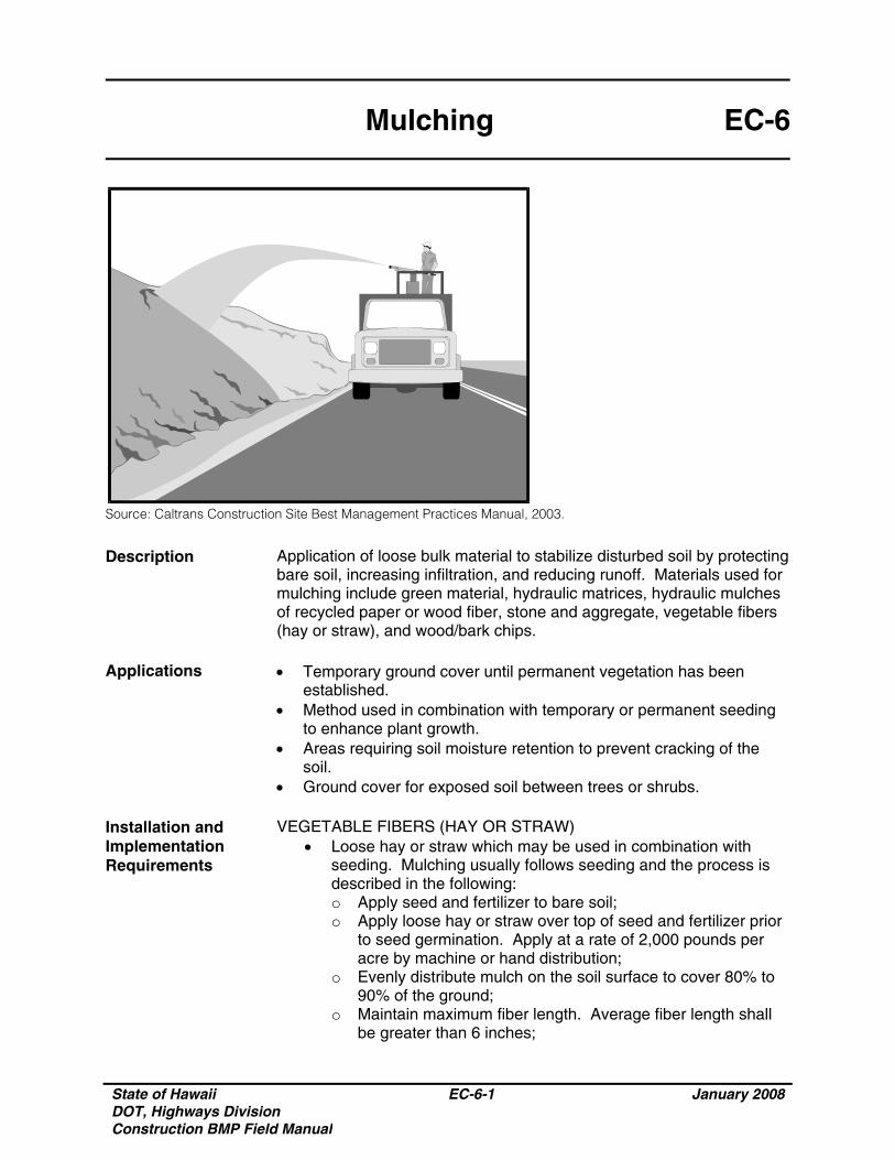
State of Hawaii DOT, Highways Division Construction BMP Field Manual
EC-6-1 January 2008
Mulching EC-6
Source: Caltrans Construction Site Best Management Practices Manual, 2003.
Description Application of loose bulk material to stabilize disturbed soil by protecting bare soil, increasing infiltration, and reducing runoff. Materials used for mulching include green material, hydraulic matrices, hydraulic mulches of recycled paper or wood fiber, stone and aggregate, vegetable fibers (hay or straw), and wood/bark chips.
Applications • Temporary ground cover until permanent vegetation has been
established. • Method used in combination with temporary or permanent seeding
to enhance plant growth. • Areas requiring soil moisture retention to prevent cracking of the
soil. • Ground cover for exposed soil between trees or shrubs.
Installation and Implementation Requirements
VEGETABLE FIBERS (HAY OR STRAW) • Loose hay or straw which may be used in combination with
seeding. Mulching usually follows seeding and the process is described in the following: o Apply seed and fertilizer to bare soil; o Apply loose hay or straw over top of seed and fertilizer prior
to seed germination. Apply at a rate of 2,000 pounds per acre by machine or hand distribution;
o Evenly distribute mulch on the soil surface to cover 80% to 90% of the ground;
o Maintain maximum fiber length. Average fiber length shall be greater than 6 inches;
State of Hawaii DOT, Highways Division Construction BMP Field Manual
EC-6-2 January 2008
Mulching EC-6
Installation and Implementation Requirements (Continued)
o Use a tackifier, netting, or mechanical “punching” method to anchor mulch. Method depends on slope steepness, accessibility, soil conditions, and longevity; and
o “Punching” straw or hay into soil is the preferred method of anchoring mulch for the following conditions: - Use a spade or shovel on small areas, - Use a knife-blade roller or straight bladed coulter
(“crimper”) on slopes with soil, which can support construction equipment without undesirable compaction or instability,
- Use plastic netting or jute on small areas and/or steep slopes. Geotextile pins, wooden stakes, or 11 gauge wire staples shall secure netting in place. This condition warrants consideration of the use of matting rather than mulch, and
- Use tackifiers on steep slopes unable to support construction equipment or large application areas where use of nettings, straw, or hay is not cost-effective. Tackifiers glue vegetable fibers together and to the soil surface until the establishment of permanent vegetation.
GREEN MATERIAL • Consists of recycled vegetation trimmings such as grass and
shredded shrubs and trees. • Generally applied by hand. • Temporary ground cover with or without seeding. • Evenly distribute green material on soil surface. Depth shall not
exceed 4 inches. • Anchor with a tackifier or netting on steep slopes or for areas
with anticipated overland sheet flow. This condition warrants consideration of the use of matting rather than mulch.
WOOD/BARK CHIPS • Suitable for areas which will not be mowed such as around
trees, shrubs, and landscape plantings. • Test soils prior to application. Add a minimum of 12 pounds of
nitrogen per ton of mulch to counteract the effect of decomposing wood-based materials, which extract nitrogen from soil. Use a balanced, slow-release fertilizer or an organic source such as compost.
• Apply mulch by hand. • Evenly distribute wood/bark chips on soil surface and maintain a
mulch depth of 2-inch to tree basins and 4-inch to shrub beds. HYDRAULIC MULCHES OF RECYCLED PAPER
• Consists of recycled newsprint, magazines, and other waste paper sources.
• May be applied with or without tackifiers.
State of Hawaii DOT, Highways Division Construction BMP Field Manual
EC-6-3 January 2008
Mulching EC-6
Installation and Implementation Requirements (Continued)
• Hydraulic mulch materials shall conform to 2005 Hawaii Standard Specifications for Road and Bridge Construction.
• Mix mulch in a hydraulic application machine (hydroseeder) and apply as a liquid slurry.
• May be sprayed from a cannon up to 200 feet or from a hose up to 1,500 feet away from the application area.
• Mix mulch with seed and fertilizer as specified by the manufacturer. Apply mulch at the manufacturer’s recommended rate to ensure uniform, effective coverage.
HYDRAULIC MULCHES OF WOOD FIBER • Consists of wood waste from lumber mills or urban sources. • May be manufactured with or without a tackifier. • Hydraulic mulch shall conform to 2005 Hawaii Standard
Specifications for Road and Bridge Construction or comply with the following requirements: o 100% wood fiber; o Maximum moisture content (total weight basis) shall not
exceed 12% ±3%; o Minimum organic matter content (oven dry weight basis) of
99.3%; o Maximum inorganic matter (ash) content (oven dried basis)
of 0.7%; o pH of 4.9±10% for a 3% water slurry; and o Minimum water holding capacity (oven dried basis) of 1.2
gallons per pound of fiber. • Mix mulch in a hydraulic application machine (hydroseeder) and
apply as a liquid slurry. • Mix mulch with seed and fertilizer as specified by the
manufacturer. Apply mulch at the manufacturer’s recommended rate to ensure uniform, effective coverage.
HYDRAULIC MATRICES • Hydraulic slurries consisting of wood fiber, paper fiber, or a
combination of wood and paper fiber mixed with a binder system.
• Exceeds erosion control performance of blankets due to close contact with soil.
• Apply as an aqueous slurry (with seed) using standard hydroseeding equipment.
• Applications rates vary for different combinations of conditions and products.
• A typical mixture based on one acre of treated area includes the following: o 500 pounds wood fiber mulch; o 1,000 pounds recycled paper mulch; and
State of Hawaii DOT, Highways Division Construction BMP Field Manual
EC-6-4 January 2008
Mulching EC-6
Installation and Implementation Requirements (Continued)
o 55 gallons acrylic copolymer with a minimum solids content of 55%.
• Bonded Fiber Matrix (BFM) consists of premixed fiber and binders. o After application and upon drying, BFM shall adhere to soil
and form a 100% cover. The cover shall be biodegradable, promote vegetation, and prevent soil erosion.
o Composed of long strand, thermally produced wood fibers (>88% of total volume by weight), held together by organic tackifiers (10%) and mineral bonding agents (<2%), which become insoluble and non-dispersible upon drying. Composition of BFM varies based on supplier.
o Perform a free liquid quality control test on the liquid slurry. o Binder shall not dissolve or disperse upon watering. o Upon application to the soil, holes in the matrix shall not
exceed 0.04 inches in size. o There shall not be any gaps between the matrix and the soil.o Minimum water holding capacity of the matrix shall be 1.2
gallons per pound matrix. o The matrix shall be free of germination or growth inhibiting
factors and shall not form a water resistant crust. o Materials used for the matrix shall be 100% biodegradable
and 100% beneficial to plant growth. o Testing and evaluation of the matrix by an independent
research laboratory shall have been conducted to verify reported erosion control performance.
o A trained and manufacturer certified applicator with knowledge of proper mixing and product application shall install the BFM.
o Typical BFM application rates range from 3,000 to 8,000 pounds per acre per recommendations from various manufacturers.
o BFM shall not be applied immediately before, during, or after a rainfall event to ensure a drying time of 24 hours after installation.
• Mulch used as temporary ground cover shall be reapplied to bare
areas until permanent vegetation has been established. • Avoid spraying mulch onto sidewalk, lined drainage channels,
travelway, and existing vegetation. Limitations
VEGETABLE FIBERS (HAY OR STRAW) • Require three-step machinery. • Labor intensive installation. • Weed seeds and undesirable plant material may be introduced
to sensitive areas.
State of Hawaii DOT, Highways Division Construction BMP Field Manual
EC-6-5 January 2008
Mulching EC-6
Limitations (Continued)
• For applications using straw blowers, the applicable area must be located within 150 feet of a road or surface capable of supporting loads from large vehicles. If both hay and straw are available, it is preferable to use straw.
GREEN MATERIAL
• Limited commercial availability. • Variable quality. • Weeds or undesirable plant material may be introduced to the
mulched area. • Application primarily uses manual labor. • Unpredictable effectiveness as an erosion control measure.
Requires overspray with a tackifying agent to increase effectiveness.
• Application of fertilizer may be required. • Limit use to non-critical steep slopes and areas where
alternative erosion control measures may be readily applied.
WOOD/BARK CHIPS • Poor erosion control effectiveness. • Anchoring of chips onto steep slopes is difficult due to potential
movement from high winds. • Subject to displacement from concentrated flows. • Use of a fertilizer with high nitrogen content is required to
prevent nutrient deficiency in plants due to decomposing wood-based materials, which extract nitrogen from soil. Improper fertilizer use may contribute to water quality pollution.
• Limit use to non-critical steep slopes and areas where alternative erosion control measures may be readily applied.
HYDRAULIC MULCHES OF RECYCLED PAPER
• Limited erosion control effectiveness due to short fiber length and absence of a tackifier.
• Limited moisture and soil temperature moderation. • Residual inks within mulches may be undesirable in
environmentally sensitive areas. • Significant decrease in longevity compared with wood fiber
mulch. • Difficulty budgeting for this product due to volatile prices for
recycled paper products.
HYDRAULIC MULCHES OF WOOD FIBER • Limited erosion control effectiveness. • Short-term use of one growing season.
State of Hawaii DOT, Highways Division Construction BMP Field Manual
EC-6-6 January 2008
Mulching EC-6
Limitations (Continued)
HYDRAULIC MATRICES • Avoid application of mulch immediately before, during, or after a
rainfall event. • Requires drying time of 24 hours.
Inspections and Maintenance
• Mulches applied to seeded areas may be disturbed due to wind or runoff. Recover exposed areas until permanent vegetation has been established.
• Mulches applied to areas, which will be regraded and revegetated, shall be inspected weekly.
• Replace ornamental and landscape mulches of bark or wood chips if soil is visible in more than 75% of the designated area.
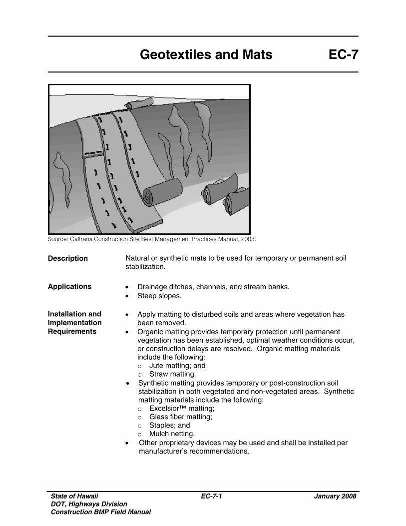
State of Hawaii DOT, Highways Division Construction BMP Field Manual
EC-7-1 January 2008
Geotextiles and Mats EC-7
Source: Caltrans Construction Site Best Management Practices Manual, 2003.
Description Natural or synthetic mats to be used for temporary or permanent soil stabilization.
Applications • Drainage ditches, channels, and stream banks.
• Steep slopes. Installation and Implementation Requirements
• Apply matting to disturbed soils and areas where vegetation has been removed.
• Organic matting provides temporary protection until permanent vegetation has been established, optimal weather conditions occur, or construction delays are resolved. Organic matting materials include the following: o Jute matting; and o Straw matting.
• Synthetic matting provides temporary or post-construction soil stabilization in both vegetated and non-vegetated areas. Synthetic matting materials include the following: o Excelsior™ matting; o Glass fiber matting; o Staples; and o Mulch netting.
• Other proprietary devices may be used and shall be installed per manufacturer’s recommendations.
State of Hawaii DOT, Highways Division Construction BMP Field Manual
EC-7-2 January 2008
Geotextiles and Mats EC-7
Limitations • Minimize use of matting to areas where other erosion control measures are not applicable such as channels or steep slopes since matting is more costly compared to other erosion control measures.
• Seed germination may be delayed due to decreased soil temperature.
• An experienced maintenance engineer is required during installation.
Inspections and Maintenance
Periodically inspect matting after installation.
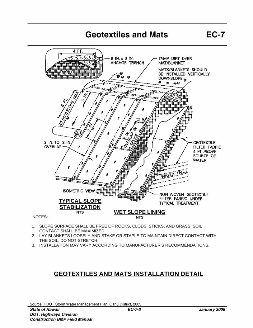
Geotextiles and Mats EC-7
Source: HDOT Storm Water Management Plan, Oahu District, 2003. State of Hawaii DOT, Highways Division Construction BMP Field Manual
EC-7-3 January 2008
TYPICAL SLOPE STABILIZATION
NTS WET SLOPE LINING NTS
GEOTEXTILES AND MATS INSTALLATION DETAIL
1. SLOPE SURFACE SHALL BE FREE OF ROCKS, CLODS, STICKS, AND GRASS. SOIL CONTACT SHALL BE MAXIMIZED.
2. LAY BLANKETS LOOSELY AND STAKE OR STAPLE TO MAINTAIN DIRECT CONTACT WITH THE SOIL. DO NOT STRETCH.
3. INSTALLATION MAY VARY ACCORDING TO MANUFACTURER’S RECOMMENDATIONS.
NOTES:
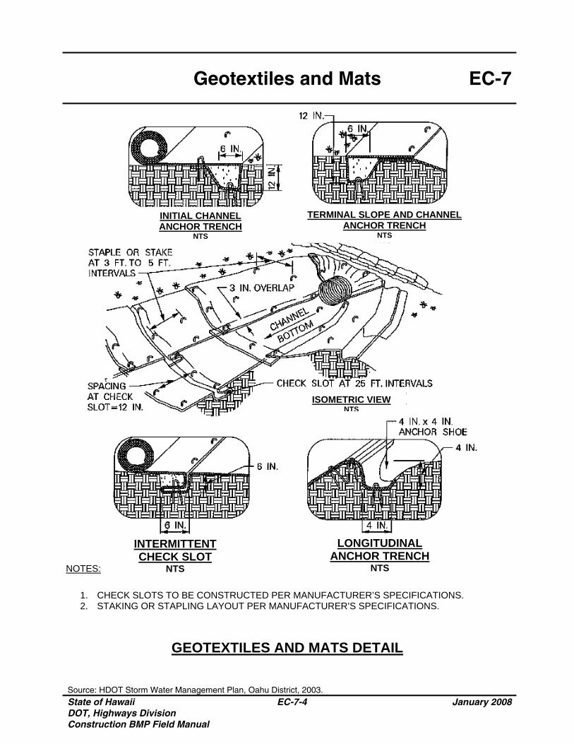
Geotextiles and Mats EC-7
Source: HDOT Storm Water Management Plan, Oahu District, 2003. State of Hawaii DOT, Highways Division Construction BMP Field Manual
EC-7-4 January 2008
NOTES:
INTERMITTENT CHECK SLOT
NTS
LONGITUDINAL ANCHOR TRENCH
NTS
1. CHECK SLOTS TO BE CONSTRUCTED PER MANUFACTURER’S SPECIFICATIONS. 2. STAKING OR STAPLING LAYOUT PER MANUFACTURER’S SPECIFICATIONS.
ISOMETRIC VIEW NTS
TERMINAL SLOPE AND CHANNEL ANCHOR TRENCH
NTS
INITIAL CHANNEL ANCHOR TRENCH
NTS
GEOTEXTILES AND MATS DETAIL
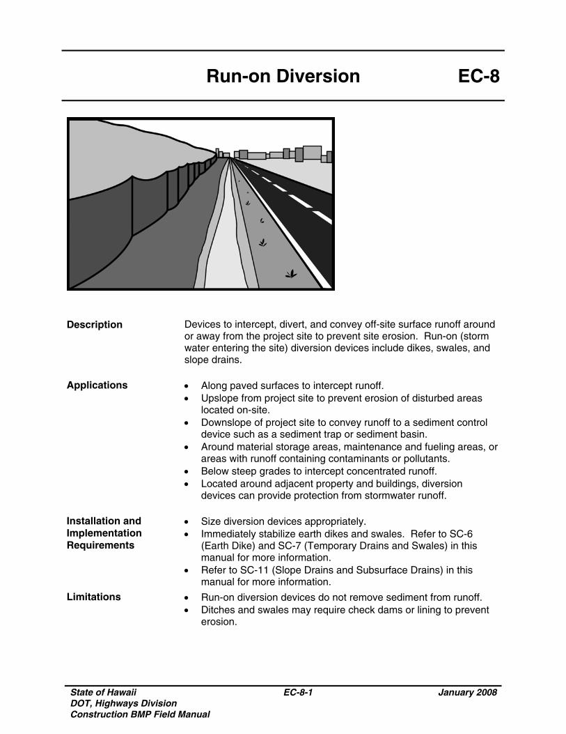
State of Hawaii DOT, Highways Division Construction BMP Field Manual
EC-8-1 January 2008
Run-on Diversion EC-8
Description Devices to intercept, divert, and convey off-site surface runoff around or away from the project site to prevent site erosion. Run-on (storm water entering the site) diversion devices include dikes, swales, and slope drains.
Applications • Along paved surfaces to intercept runoff.
• Upslope from project site to prevent erosion of disturbed areas located on-site.
• Downslope of project site to convey runoff to a sediment control device such as a sediment trap or sediment basin.
• Around material storage areas, maintenance and fueling areas, or areas with runoff containing contaminants or pollutants.
• Below steep grades to intercept concentrated runoff. • Located around adjacent property and buildings, diversion
devices can provide protection from stormwater runoff. Installation and Implementation Requirements
• Size diversion devices appropriately. • Immediately stabilize earth dikes and swales. Refer to SC-6
(Earth Dike) and SC-7 (Temporary Drains and Swales) in this manual for more information.
• Refer to SC-11 (Slope Drains and Subsurface Drains) in this manual for more information.
Limitations • Run-on diversion devices do not remove sediment from runoff. • Ditches and swales may require check dams or lining to prevent
erosion.
State of Hawaii DOT, Highways Division Construction BMP Field Manual
EC-8-2 January 2008
Run-on Diversion EC-8
Inspections and Maintenance
• Inspect weekly during dry periods as well as within 24 hours of any rainfall of 0.5 inch or greater which occurs in a 24-hour period and daily during periods of prolonged rainfall.
• Inspect channels embankments, and ditch beds for erosion, washout, and accumulated sediment and debris.
• Remove accumulated sediment and debris and repair damages as necessary.
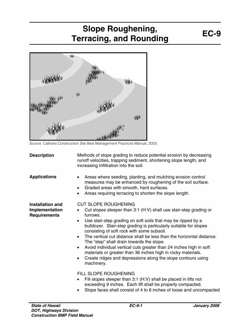
State of Hawaii DOT, Highways Division Construction BMP Field Manual
EC-9-1 January 2008
Slope Roughening, Terracing, and Rounding
EC-9
Source: Caltrans Construction Site Best Management Practices Manual, 2003.
Description Methods of slope grading to reduce potential erosion by decreasing runoff velocities, trapping sediment, shortening slope length, and increasing infiltration into the soil.
Applications • Areas where seeding, planting, and mulching erosion control
measures may be enhanced by roughening of the soil surface. • Graded areas with smooth, hard surfaces. • Areas requiring terracing to shorten the slope length.
Installation and Implementation Requirements
CUT SLOPE ROUGHENING • Cut slopes steeper than 3:1 (H:V) shall use stair-step grading or
furrows. • Use stair-step grading on soft soils that may be ripped by a
bulldozer. Stair-step grading is particularly suitable for slopes consisting of soft rock with some subsoil.
• The vertical cut distance shall be less than the horizontal distance. The “step” shall drain towards the slope.
• Avoid individual vertical cuts greater than 24 inches high in soft materials or greater than 36 inches high in rocky materials.
• Create ridges and depressions along the slope contours using machinery.
FILL SLOPE ROUGHENING • Fill slopes steeper than 3:1 (H:V) shall be placed in lifts not
exceeding 9 inches. Each lift shall be properly compacted. • Slope faces shall consist of 4 to 6 inches of loose and uncompacted
State of Hawaii DOT, Highways Division Construction BMP Field Manual
EC-9-2 January 2008
Slope Roughening, Terracing, and Rounding
EC-9
Installation and Implementation Requirements (Continued)
soil. • Grooving or tracking shall be used to roughen slope faces as
necessary. • Apply seed, fertilizer, and mulch. Track or punch in the mulch.
Refer to EC-6 (Mulching) and EC-5 (Seeding and Planting) in this manual for additional information.
• The final slope face shall not be bladed or scraped. CUTS, FILLS, AND GRADED AREAS • Slopes that will be maintained by mowing shall be no steeper than
3:1 (H:V). • Create shallow grooves by normal tilling, disking, harrowing, or use
of a cultivator-seeder. Final pass of tillage shall be along the contour. Spacing between grooves shall be 10 inches or less. Groove depth shall be a minimum of 1 inch.
ROUGHENING WITH TRACKED MACHINERY • Roughening with tracked machinery is only applicable to soils with a
sandy texture. Other types of soil may be over-compacted by tracked machinery.
• Leave horizontal depressions in the soil by operating tracked machinery up and down the slope. During the final grading operation, do not back blade.
• Roughened areas shall be seeded and mulched for optimum seed germination and growth.
TERRACING • Slope grades of 5:1 (H:V) shall include terraces or benches when
slope heights exceed 30 feet. Steeper slope or highly erosive soil conditions may warrant terraces or benches for slope heights of 15 feet of higher.
• Runoff collected along terraces and benches shall be routed to lined diversion ditches. Install lined diversion ditches at the intersection of the terrace and slope.
ROUNDING • All slopes shall be rounded with no sharp breaks in plan or profile.
Limitations
• Since terracing is permanent, design and approval shall be under the direction of a licensed, qualified engineer.
• Design of terraces shall provide adequate drainage and stabilized outlets.
• Roughening may result in increased grading costs and sloughing in soil.
State of Hawaii DOT, Highways Division Construction BMP Field Manual
EC-9-3 January 2008
Slope Roughening, Terracing, and Rounding
EC-9
Limitations (Continued)
• Stair-step grading may not be applicable to sandy, steep, or shallow soils.
• During intense rainfall events, roughening may not be an effective temporary erosion control measure.
Inspections and Maintenance
Inspect seeded and planted slopes for rills and gullies weekly during dry periods as well as within 24 hours of any rainfall of 0.5 inch or greater which occurs in a 24-hour period and daily during periods of prolonged rainfall.
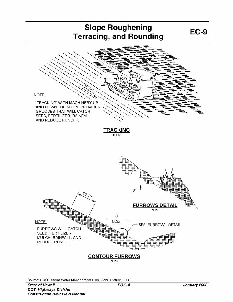
Slope Roughening
Terracing, and Rounding EC-9
Source: HDOT Storm Water Management Plan, Oahu District, 2003. State of Hawaii DOT, Highways Division Construction BMP Field Manual
EC-9-4 January 2008
CONTOUR FURROWS NTS
TRACKING NTS
FURROWS DETAIL NTS
NOTE:
NOTE:
FURROWS WILL CATCH SEED, FERTILIZER, MULCH, RAINFALL, AND REDUCE RUNOFF.
‘TRACKING’ WITH MACHINERY UP AND DOWN THE SLOPE PROVIDES GROOVES THAT WILL CATCH SEED, FERTILIZER, RAINFALL, AND REDUCE RUNOFF.
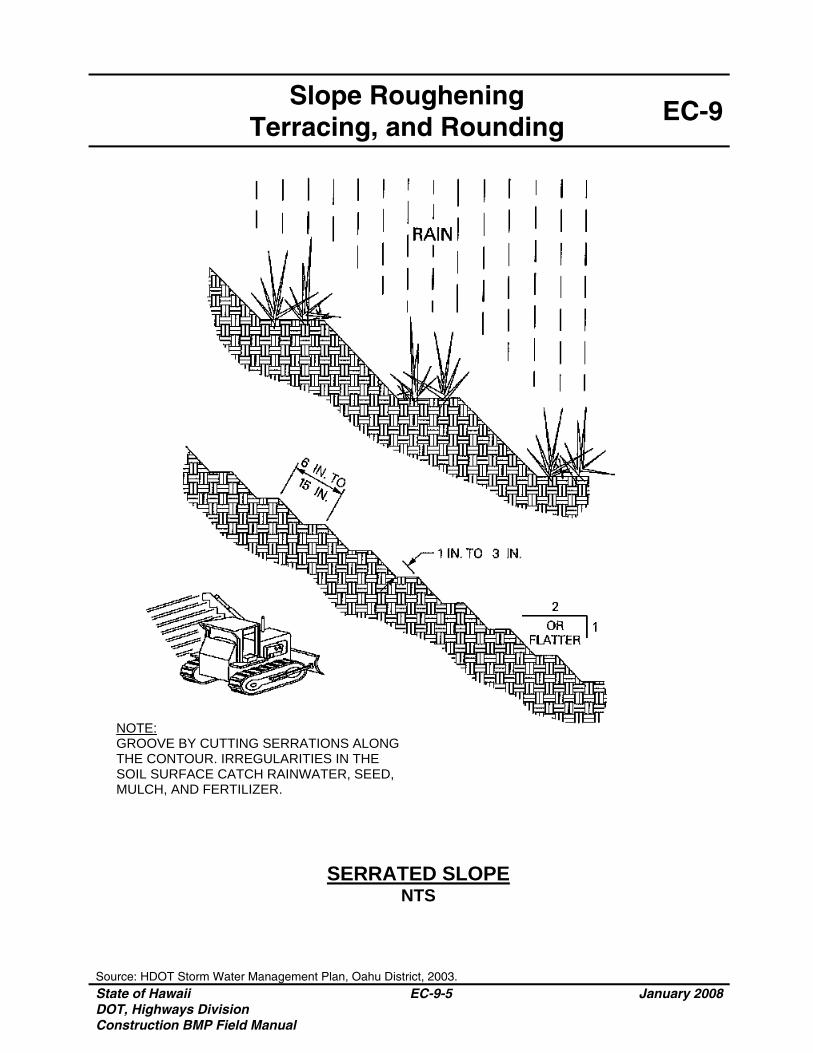
Slope Roughening
Terracing, and Rounding EC-9
Source: HDOT Storm Water Management Plan, Oahu District, 2003. State of Hawaii DOT, Highways Division Construction BMP Field Manual
EC-9-5 January 2008
SERRATED SLOPE NTS
NOTE: GROOVE BY CUTTING SERRATIONS ALONG THE CONTOUR. IRREGULARITIES IN THE SOIL SURFACE CATCH RAINWATER, SEED, MULCH, AND FERTILIZER.
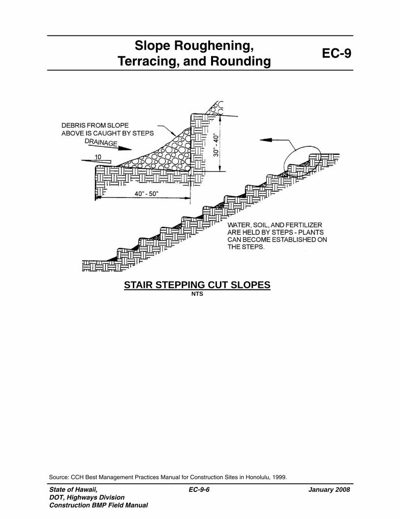
State of Hawaii, DOT, Highways Division Construction BMP Field Manual
January 2008
EC-9-6
EC-9 Slope Roughening,
Terracing, and Rounding
STAIR STEPPING CUT SLOPES NTS
Source: CCH Best Management Practices Manual for Construction Sites in Honolulu, 1999.
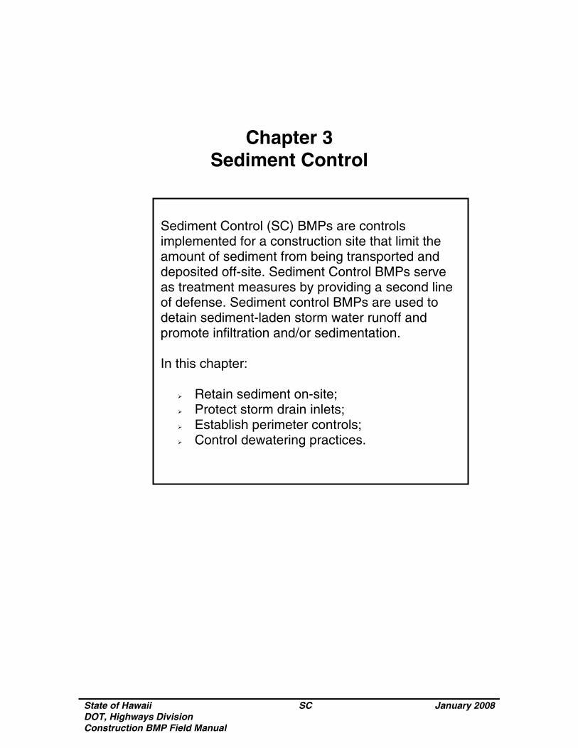
State of Hawaii DOT, Highways Division Construction BMP Field Manual
SC January 2008
Chapter 3 Sediment Control
Sediment Control (SC) BMPs are controls implemented for a construction site that limit the amount of sediment from being transported and deposited off-site. Sediment Control BMPs serve as treatment measures by providing a second line of defense. Sediment control BMPs are used to detain sediment-laden storm water runoff and promote infiltration and/or sedimentation. In this chapter:
Retain sediment on-site; Protect storm drain inlets; Establish perimeter controls; Control dewatering practices.

State of Hawaii DOT, Highways Division Construction BMP Field Manual
SC January 2008
THIS PAGE INTENTIONALLY LEFT BLANK
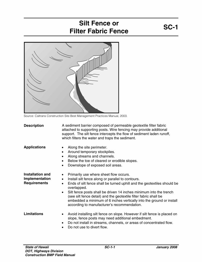
State of Hawaii DOT, Highways Division Construction BMP Field Manual
SC-1-1 January 2008
Silt Fence or Filter Fabric Fence
SC-1
Source: Caltrans Construction Site Best Management Practices Manual, 2003.
Description A sediment barrier composed of permeable geotextile filter fabric attached to supporting posts. Wire fencing may provide additional support. The silt fence intercepts the flow of sediment laden runoff, which filters the water and traps the sediment.
Applications • Along the site perimeter.
• Around temporary stockpiles. • Along streams and channels. • Below the toe of cleared or erodible slopes. • Downslope of exposed soil areas.
Installation and Implementation Requirements
• Primarily use where sheet flow occurs. • Install silt fence along or parallel to contours. • Ends of silt fence shall be turned uphill and the geotextiles should be
overlapped. • Silt fence posts shall be driven 14 inches minimum into the trench
(see silt fence detail) and the geotextile filter fabric shall be embedded a minimum of 6 inches vertically into the ground or install according to manufacturer’s recommendation.
Limitations • Avoid installing silt fence on slope. However if silt fence is placed on
slope, fence posts may need additional embedment. • Do not install in streams, channels, or areas of concentrated flow. • Do not use to divert flow.
State of Hawaii DOT, Highways Division Construction BMP Field Manual
SC-1-2 January 2008
Silt Fence or Filter Fabric Fence
SC-1
Inspections and Maintenance
• Inspect weekly during dry periods as well as within 24 hours of any
rainfall of 0.5 inch or greater which occurs in a 24-hour period and daily during periods of prolonged rainfall.
• Repair or replace damaged fence or posts. • Remove accumulated sediment when depth reaches 1/3 the barrier
height.
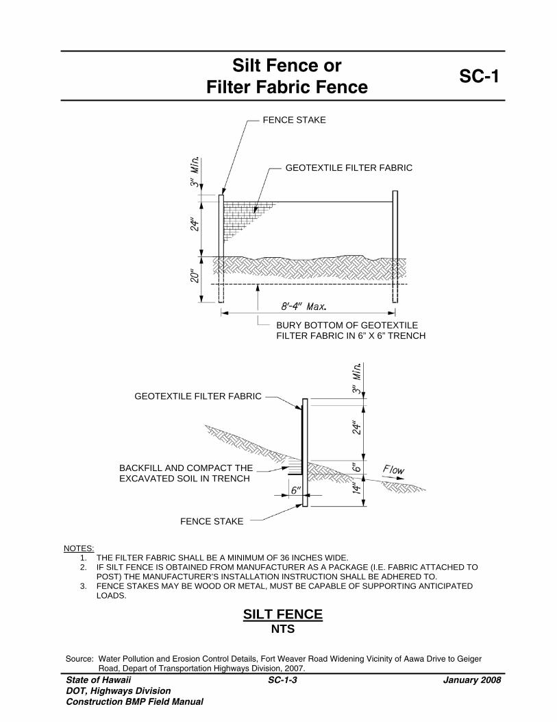
Silt Fence or
Filter Fabric Fence SC-1
Source: Water Pollution and Erosion Control Details, Fort Weaver Road Widening Vicinity of Aawa Drive to Geiger Road, Depart of Transportation Highways Division, 2007.
State of Hawaii DOT, Highways Division Construction BMP Field Manual
SC-1-3 January 2008
NOTES: 1. THE FILTER FABRIC SHALL BE A MINIMUM OF 36 INCHES WIDE. 2. IF SILT FENCE IS OBTAINED FROM MANUFACTURER AS A PACKAGE (I.E. FABRIC ATTACHED TO
POST) THE MANUFACTURER’S INSTALLATION INSTRUCTION SHALL BE ADHERED TO. 3. FENCE STAKES MAY BE WOOD OR METAL, MUST BE CAPABLE OF SUPPORTING ANTICIPATED
LOADS.
GEOTEXTILE FILTER FABRIC
BURY BOTTOM OF GEOTEXTILE FILTER FABRIC IN 6” X 6” TRENCH
GEOTEXTILE FILTER FABRIC
FENCE STAKE
BACKFILL AND COMPACT THE EXCAVATED SOIL IN TRENCH
FENCE STAKE
SILT FENCE NTS

State of Hawaii DOT, Highways Division Construction BMP Field Manual
SC-1-4 January 2008
THIS PAGE INTENTIONALLY LEFT BLANK
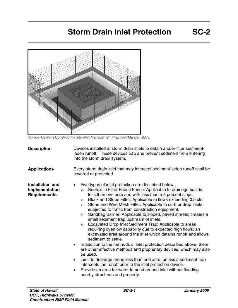
State of Hawaii DOT, Highways Division Construction BMP Field Manual
SC-2-1 January 2008
Storm Drain Inlet Protection SC-2
Source: Caltrans Construction Site Best Management Practices Manual, 2003.
Description Devices installed at storm drain inlets to detain and/or filter sediment-laden runoff. These devices trap and prevent sediment from entering into the storm drain system.
Applications Every storm drain inlet that may intercept sediment-laden runoff shall be
covered or protected. Installation and Implementation Requirements
• Five types of inlet protection are described below. o Geotextile Filter Fabric Fence: Applicable to drainage basins
less than one acre and with less than a 5 percent slope. o Block and Stone Filter: Applicable to flows exceeding 0.5 cfs. o Stone and Wire Mesh Filter: Applicable to curb or drop inlets
subjected to traffic from construction equipment. o Sandbag Barrier: Applicable to sloped, paved streets; creates a
small sediment trap upstream of inlets. o Excavated Drop Inlet Sediment Trap: Applicable to areas
requiring overflow capability due to expected high flows; an excavated area around the inlet which detains runoff and allows sediment to settle.
• In addition to the methods of inlet protection described above, there are other effective methods and proprietary devices, which may also be used.
• Limit to drainage areas less than one acre, unless a sediment trap intercepts the runoff prior to the inlet protection device.
• Provide an area for water to pond around inlet without flooding nearby structures and property.

State of Hawaii DOT, Highways Division Construction BMP Field Manual
SC-2-2 January 2008
Storm Drain Inlet Protection SC-2
Installation and Implementation Requirements (Continued)
• Other proprietary devices may be used and shall be installed per manufacturer’s recommendations.
Limitations • Short-term flooding at a protected inlet will occur but must not
become a traffic hazard. • Drainage area limited to one acre or less. • Straw bales shall not be used for inlet protection. • Runoff on slopes may bypass protected inlets
Inspections and Maintenance
• Inspect weekly during dry periods as well as within 24 hours of any rainfall of 0.5 inch or greater which occurs in a 24-hour period and daily during periods of prolonged rainfall.
• Immediately replace clogged geotextile filter fabric or stone filters. • Remove accumulated sediment when depth reaches half of the filter
height or half of the sediment trap depth. • Remove inlet protection after stabilization of upstream soils and
sweeping of streets is completed. Properly dispose of trapped sediment.
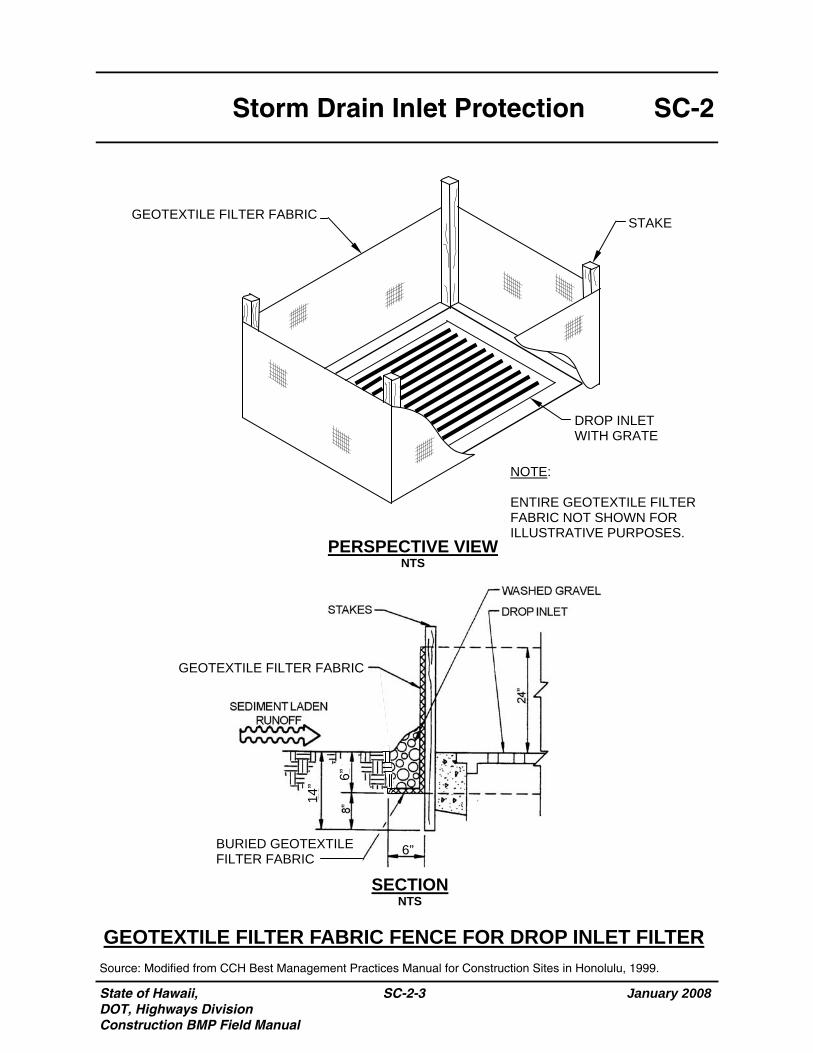
State of Hawaii, DOT, Highways Division Construction BMP Field Manual
January 2008
SC-2-3
SC-2 Storm Drain Inlet Protection
SECTION NTS
GEOTEXTILE FILTER FABRIC FENCE FOR DROP INLET FILTER
PERSPECTIVE VIEW NTS
Source: Modified from CCH Best Management Practices Manual for Construction Sites in Honolulu, 1999.
GEOTEXTILE FILTER FABRIC
BURIED GEOTEXTILE FILTER FABRIC
NOTE: ENTIRE GEOTEXTILE FILTER FABRIC NOT SHOWN FOR ILLUSTRATIVE PURPOSES.
GEOTEXTILE FILTER FABRIC STAKE
DROP INLET WITH GRATE
14”
6”
6”
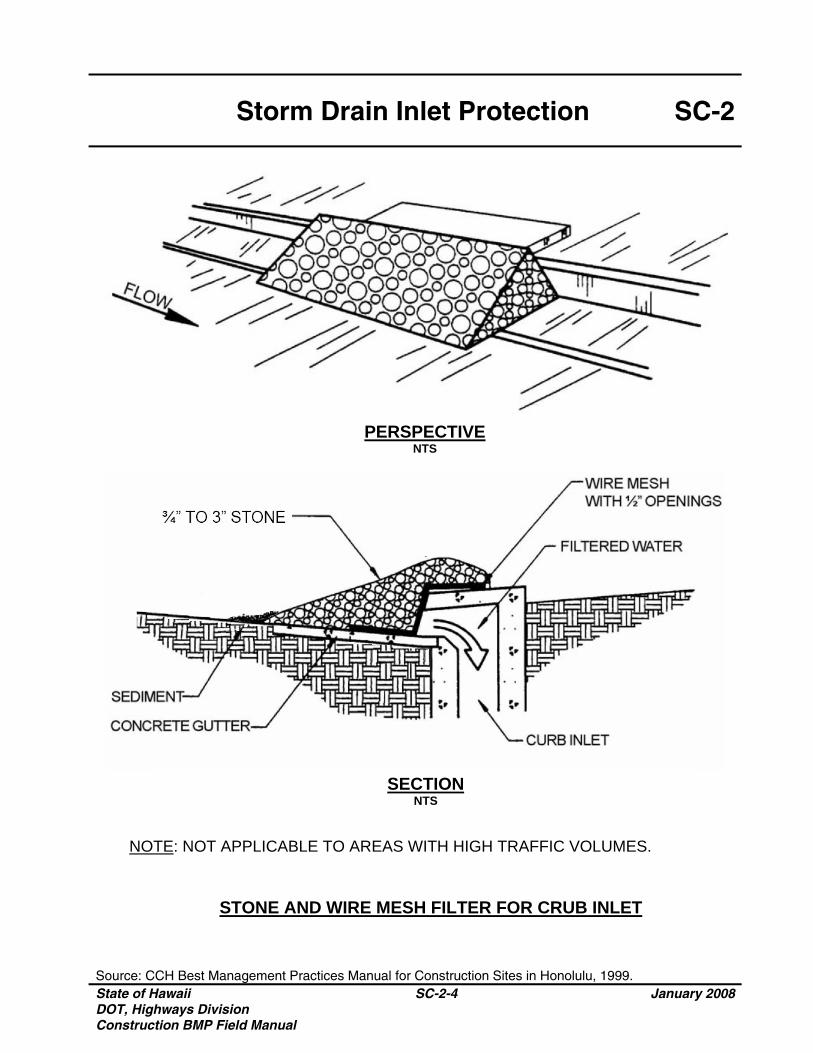
Storm Drain Inlet Protection SC-2
Source: CCH Best Management Practices Manual for Construction Sites in Honolulu, 1999. State of Hawaii DOT, Highways Division Construction BMP Field Manual
SC-2-4 January 2008
PERSPECTIVE NTS
STONE AND WIRE MESH FILTER FOR CRUB INLET
SECTION NTS
NOTE: NOT APPLICABLE TO AREAS WITH HIGH TRAFFIC VOLUMES.
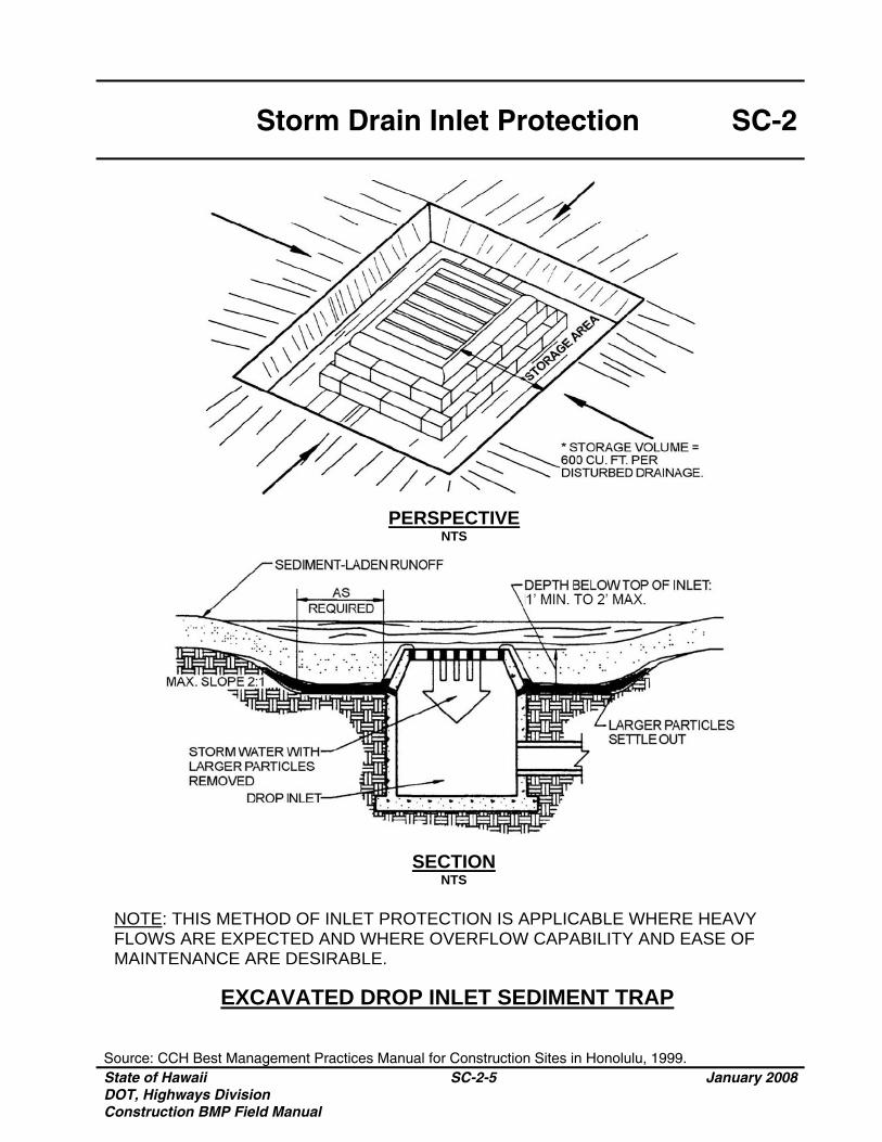
Storm Drain Inlet Protection SC-2
Source: CCH Best Management Practices Manual for Construction Sites in Honolulu, 1999. State of Hawaii DOT, Highways Division Construction BMP Field Manual
SC-2-5 January 2008
PERSPECTIVE NTS
SECTION NTS
EXCAVATED DROP INLET SEDIMENT TRAP
NOTE: THIS METHOD OF INLET PROTECTION IS APPLICABLE WHERE HEAVY FLOWS ARE EXPECTED AND WHERE OVERFLOW CAPABILITY AND EASE OF MAINTENANCE ARE DESIRABLE.
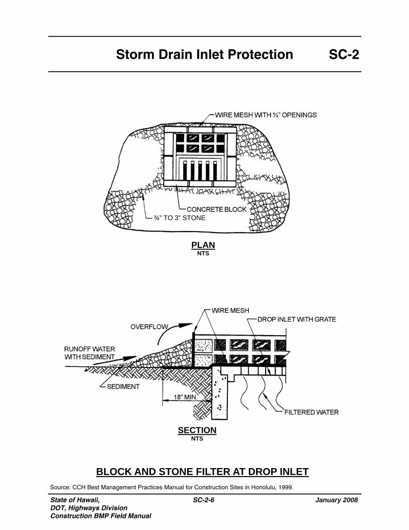
State of Hawaii, DOT, Highways Division Construction BMP Field Manual
January 2008
SC-2-6
SC-2 Storm Drain Inlet Protection
BLOCK AND STONE FILTER AT DROP INLET
SECTION NTS
PLAN NTS
Source: CCH Best Management Practices Manual for Construction Sites in Honolulu, 1999.
¾” TO 3” STONE
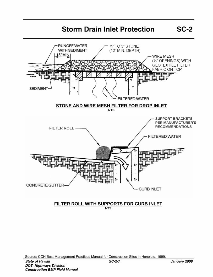
Storm Drain Inlet Protection SC-2
Source: CCH Best Management Practices Manual for Construction Sites in Honolulu, 1999. State of Hawaii DOT, Highways Division Construction BMP Field Manual
SC-2-7 January 2008
STONE AND WIRE MESH FILTER FOR DROP INLET NTS
FILTER ROLL WITH SUPPORTS FOR CURB INLET NTS
FILTER ROLL
SUPPORT BRACKETS PER MANUFACTURER'S RECOMMENDATIONS

State of Hawaii DOT, Highways Division Construction BMP Field Manual
SC-2-8 January 2008
THIS PAGE INTENTIONALLY LEFT BLANK
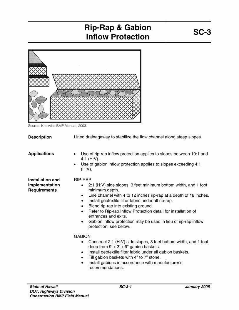
State of Hawaii DOT, Highways Division Construction BMP Field Manual
SC-3-1 January 2008
Rip-Rap & Gabion Inflow Protection
SC-3
Source: Knoxville BMP Manual, 2003.
Description Lined drainageway to stabilize the flow channel along steep slopes.
Applications • Use of rip-rap inflow protection applies to slopes between 10:1 and
4:1 (H:V). • Use of gabion inflow protection applies to slopes exceeding 4:1
(H:V). Installation and Implementation Requirements
RIP-RAP • 2:1 (H:V) side slopes, 3 feet minimum bottom width, and 1 foot
minimum depth. • Line channel with 4 to 12 inches rip-rap at a depth of 18 inches.• Install geotextile filter fabric under all rip-rap. • Blend rip-rap into existing ground. • Refer to Rip-rap Inflow Protection detail for installation of
entrances and exits. • Gabion inflow protection may be used in lieu of rip-rap inflow
protection, see below.
GABION • Construct 2:1 (H:V) side slopes, 3 feet bottom width, and 1 foot
deep from 9’ x 3’ x 9” gabion baskets. • Install geotextile filter fabric under all gabion baskets. • Fill gabion baskets with 4” to 7” stone. • Install gabions in accordance with manufacturer’s
recommendations.
State of Hawaii DOT, Highways Division Construction BMP Field Manual
SC-3-2 January 2008
Rip-Rap & Gabion Inflow Protection
SC-3
Limitations None Inspections and Maintenance
• Inspect weekly during dry periods as well as within 24 hours of any rainfall of 0.5 inch or greater which occurs in a 24-hour period and daily during periods of prolonged rainfall.
• Remove accumulated sediment at inlet structure.
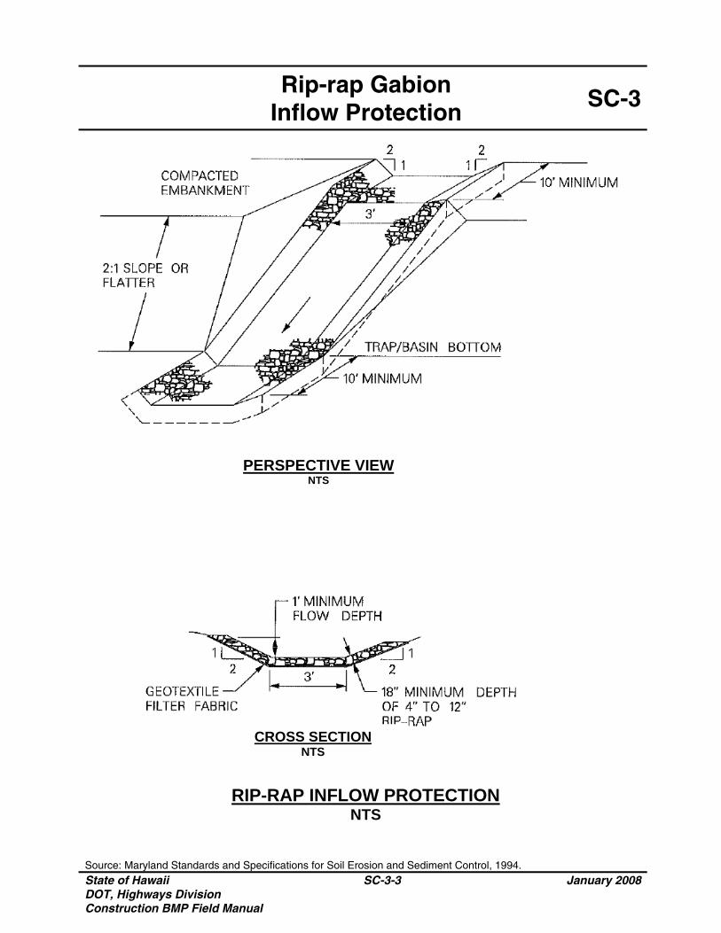
Rip-rap Gabion
Inflow Protection SC-3
Source: Maryland Standards and Specifications for Soil Erosion and Sediment Control, 1994. State of Hawaii DOT, Highways Division Construction BMP Field Manual
SC-3-3 January 2008
PERSPECTIVE VIEW NTS
CROSS SECTION NTS
RIP-RAP INFLOW PROTECTION NTS
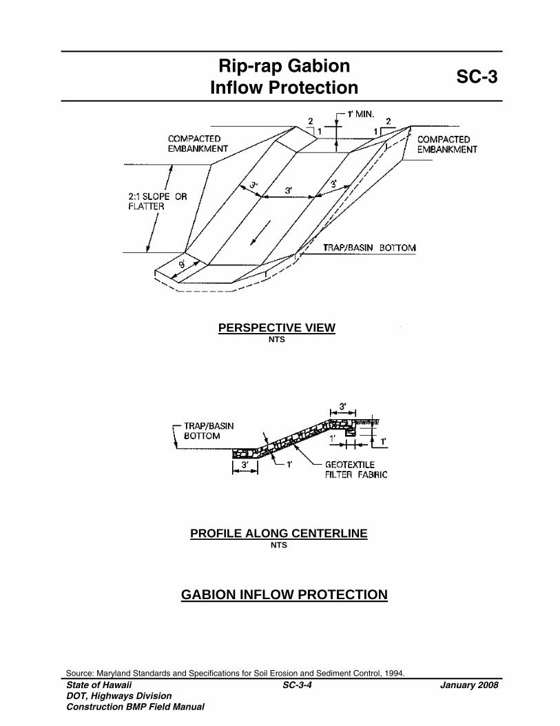
Rip-rap Gabion
Inflow Protection SC-3
Source: Maryland Standards and Specifications for Soil Erosion and Sediment Control, 1994. State of Hawaii DOT, Highways Division Construction BMP Field Manual
SC-3-4 January 2008
PERSPECTIVE VIEW NTS
PROFILE ALONG CENTERLINE NTS
GABION INFLOW PROTECTION
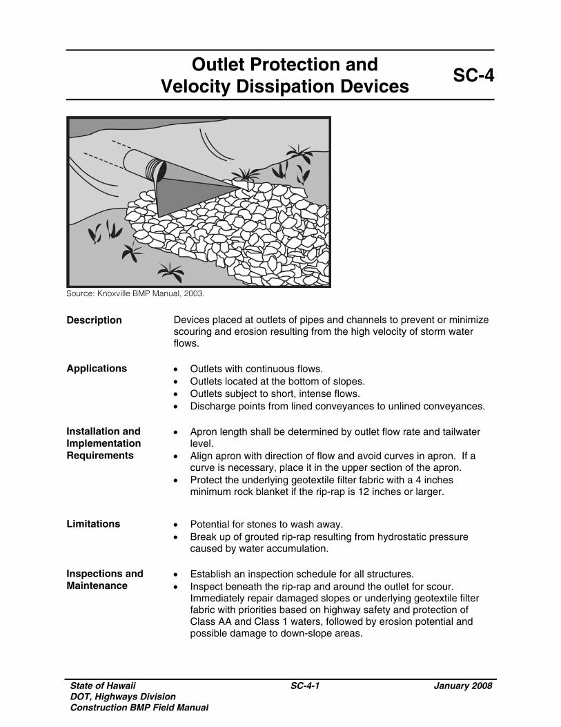
State of Hawaii DOT, Highways Division Construction BMP Field Manual
SC-4-1 January 2008
Outlet Protection and Velocity Dissipation Devices
SC-4
Source: Knoxville BMP Manual, 2003.
Description Devices placed at outlets of pipes and channels to prevent or minimize scouring and erosion resulting from the high velocity of storm water flows.
Applications • Outlets with continuous flows.
• Outlets located at the bottom of slopes. • Outlets subject to short, intense flows. • Discharge points from lined conveyances to unlined conveyances.
Installation and Implementation Requirements
• Apron length shall be determined by outlet flow rate and tailwater level.
• Align apron with direction of flow and avoid curves in apron. If a curve is necessary, place it in the upper section of the apron.
• Protect the underlying geotextile filter fabric with a 4 inches minimum rock blanket if the rip-rap is 12 inches or larger.
Limitations • Potential for stones to wash away.
• Break up of grouted rip-rap resulting from hydrostatic pressure caused by water accumulation.
Inspections and Maintenance
• Establish an inspection schedule for all structures. • Inspect beneath the rip-rap and around the outlet for scour.
Immediately repair damaged slopes or underlying geotextile filter fabric with priorities based on highway safety and protection of Class AA and Class 1 waters, followed by erosion potential and possible damage to down-slope areas.

State of Hawaii DOT, Highways Division Construction BMP Field Manual
SC-4-2 January 2008
Outlet Protection and Velocity Dissipation Devices
SC-4
Inspections and Maintenance (Continued)
• Inspect apron for damage to underlying geotextile filter fabric or dislodged rip-rap. Report any damage exceeding 10% of the apron surface area for evaluation by the HWY-OM Engineer or Highway Design Section, as appropriate.
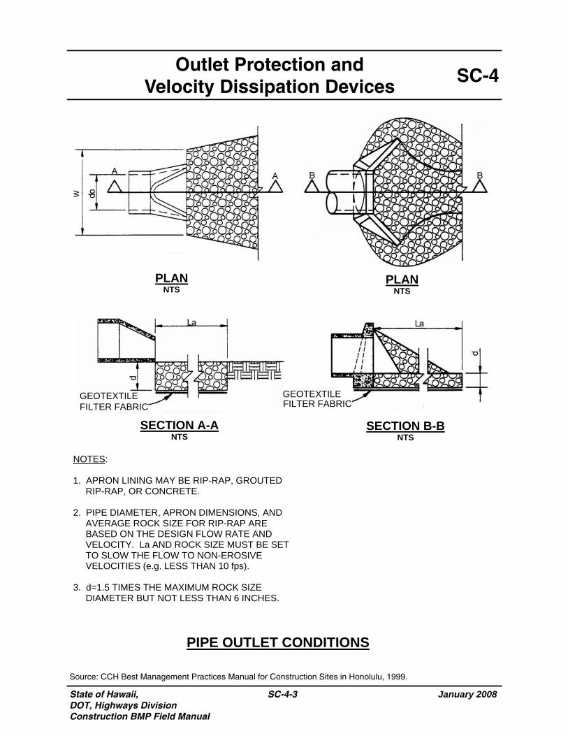
State of Hawaii, DOT, Highways Division Construction BMP Field Manual
January 2008
SC-4-3
SC-4 Outlet Protection and
Velocity Dissipation Devices
PIPE OUTLET CONDITIONS
Source: CCH Best Management Practices Manual for Construction Sites in Honolulu, 1999.
PLAN NTS
PLAN NTS
SECTION B-B NTS
SECTION A-A NTS
FILTER FABRIC GEOTEXTILE
FILTER FABRIC GEOTEXTILE
NOTES: 1. APRON LINING MAY BE RIP-RAP, GROUTED
RIP-RAP, OR CONCRETE. 2. PIPE DIAMETER, APRON DIMENSIONS, AND
AVERAGE ROCK SIZE FOR RIP-RAP ARE BASED ON THE DESIGN FLOW RATE AND VELOCITY. La AND ROCK SIZE MUST BE SET TO SLOW THE FLOW TO NON-EROSIVE VELOCITIES (e.g. LESS THAN 10 fps).
3. d=1.5 TIMES THE MAXIMUM ROCK SIZE DIAMETER BUT NOT LESS THAN 6 INCHES.
w

State of Hawaii DOT, Highways Division Construction BMP Field Manual
SC-4-4 January 2008
THIS PAGE INTENTIONALLY LEFT BLANK
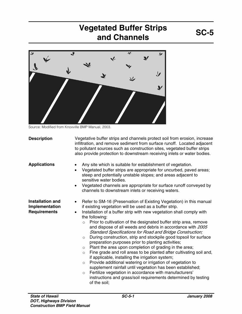
State of Hawaii DOT, Highways Division Construction BMP Field Manual
SC-5-1 January 2008
Vegetated Buffer Strips and Channels
SC-5
Source: Modified from Knoxville BMP Manual, 2003.
Description Vegetative buffer strips and channels protect soil from erosion, increase infiltration, and remove sediment from surface runoff. Located adjacent to pollutant sources such as construction sites, vegetated buffer strips also provide protection to downstream receiving inlets or water bodies.
Applications • Any site which is suitable for establishment of vegetation.
• Vegetated buffer strips are appropriate for uncurbed, paved areas; steep and potentially unstable slopes; and areas adjacent to sensitive water bodies.
• Vegetated channels are appropriate for surface runoff conveyed by channels to downstream inlets or receiving waters.
Installation and Implementation Requirements
• Refer to SM-16 (Preservation of Existing Vegetation) in this manual if existing vegetation will be used as a buffer strip.
• Installation of a buffer strip with new vegetation shall comply with the following: o Prior to cultivation of the designated buffer strip area, remove
and dispose of all weeds and debris in accordance with 2005 Standard Specifications for Road and Bridge Construction;
o During construction, strip and stockpile good topsoil for surface preparation purposes prior to planting activities;
o Plant the area upon completion of grading in the area; o Fine grade and roll areas to be planted after cultivating soil and,
if applicable, installing the irrigation system; o Provide additional watering or irrigation of vegetation to
supplement rainfall until vegetation has been established; o Fertilize vegetation in accordance with manufacturers’
instructions and grass/soil requirements determined by testing of the soil;
State of Hawaii DOT, Highways Division Construction BMP Field Manual
SC-5-2 January 2008
Vegetated Buffer Strips and Channels
SC-5
Installation and Implementation Requirements (Continued)
o Vehicular traffic passing through vegetated buffer strips or channels shall be avoided to protect vegetation from damage and maximize its effectiveness;
o Comply with applicable regulations and manufacturers’ instructions when applying fertilizers, pesticides, soil amendments, or chemicals;
o Comply with the following during seeding activities: - Add soil amendments such as fertilizer when preparing
seedbed. Apply mulch after seeding to protect vegetation during establishment. Select an appropriate seed mixture based on site conditions. Dense grasses are more effective in reducing flow velocities and removing sediment. Thick root structures are necessary for erosion control,
- Use proper equipment and methods to ensure uniform distribution and appropriate seed placement, and
- Overseed, repair bare spots, and apply additional mulch as necessary; and
o Comply with the following during sodding activities: - Protect sod with tarps or other types of protective covering
during delivery and do not allow sow to dry between harvesting and placement,
- Any irregular or uneven areas observed prior to or during the plant establishment period shall be restored to a smooth and even appearance,
- Prior to placing sod, ground surface shall be smooth and uniform,
- Areas, which will be planted with sod and are adjacent to paved surfaces such as sidewalks and concrete headers, shall be 1.5±0.25 inches below the top grade of the paved surface after fine grading, rolling, and settlement of the soil.
- Ends of adjacent strips of sod shall be staggered a minimum of 24 inches,
- Edges and ends of sod shall be placed firmly against paved borders,
- After placement of the sod, lightly roll sodded area to eliminate air pockets and ensure close contact with the soil,
- After rolling, water the sodded area to moisten the soil to a depth of 4 inches,
- Do not allow sod to dry, - Avoid planting sod during extremely hot or wet weather, and- Sod shall not be placed on slopes steeper than 3:1 (H:V) if
the area will be mowed. Limitations
• Site conditions such as availability of land. • Flow depth and vegetative condition determine BMP effectiveness. • May require irrigation to maintain vegetation.
State of Hawaii DOT, Highways Division Construction BMP Field Manual
SC-5-3 January 2008
Vegetated Buffer Strips and Channels
SC-5
Limitations (Continued)
• High maintenance requirements may exist depending on the design condition of the vegetation.
• Unless existing vegetation is used as a buffer strip, an area will need to be provided specifically for a buffer strip and vegetation will need to be established.
• Maintaining sheet flow in buffer strips may be difficult. • Vegetated channels require a larger area than lined channels. • Vegetated channels require gradual slopes since runoff with high
flow velocity may flow over grass rather than through it. Inspections and Maintenance
• Inspect weekly during dry periods as well as within 24 hours of any rainfall of 0.5 inch or greater which occurs in a 24-hour period and daily during periods of prolonged rainfall until vegetation is established. Repair eroded or damaged areas as necessary.
• Maintenance activities include mowing, weeding, and verification of a properly operating irrigation system, if applicable.
• Properly remove and dispose of clippings from mowing and trimming in accordance with 2005 Standard Specifications for Road and Bridge Construction.
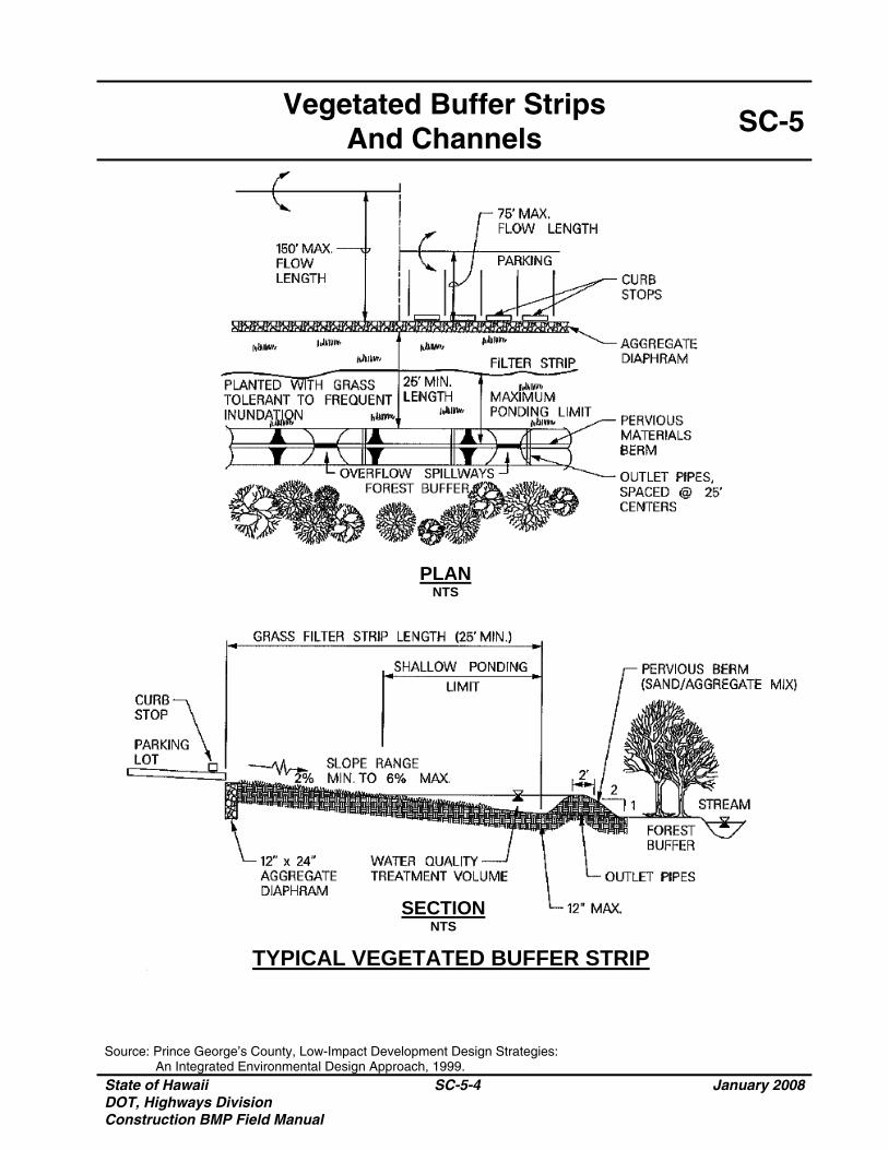
Vegetated Buffer Strips
And Channels SC-5
Source: Prince George’s County, Low-Impact Development Design Strategies: An Integrated Environmental Design Approach, 1999. State of Hawaii DOT, Highways Division Construction BMP Field Manual
SC-5-4 January 2008
PLAN NTS
SECTION NTS
TYPICAL VEGETATED BUFFER STRIP
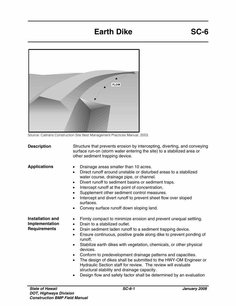
State of Hawaii DOT, Highways Division Construction BMP Field Manual
SC-6-1 January 2008
Earth Dike SC-6
Source: Caltrans Construction Site Best Management Practices Manual, 2003.
Description Structure that prevents erosion by intercepting, diverting, and conveying surface run-on (storm water entering the site) to a stabilized area or other sediment trapping device.
Applications • Drainage areas smaller than 10 acres.
• Direct runoff around unstable or disturbed areas to a stabilized water course, drainage pipe, or channel.
• Divert runoff to sediment basins or sediment traps. • Intercept runoff at the point of concentration. • Supplement other sediment control measures. • Intercept and divert runoff to prevent sheet flow over sloped
surfaces. • Convey surface runoff down sloping land.
Installation and Implementation Requirements
• Firmly compact to minimize erosion and prevent unequal settling. • Drain to a stabilized outlet. • Drain sediment laden runoff to a sediment trapping device. • Ensure continuous, positive grade along dike to prevent ponding of
runoff. • Stabilize earth dikes with vegetation, chemicals, or other physical
devices. • Conform to predevelopment drainage patterns and capacities. • The design of dikes shall be submitted to the HWY-OM Engineer or
Hydraulic Section staff for review. The review will evaluate structural stability and drainage capacity.
• Design flow and safety factor shall be determined by an evaluation
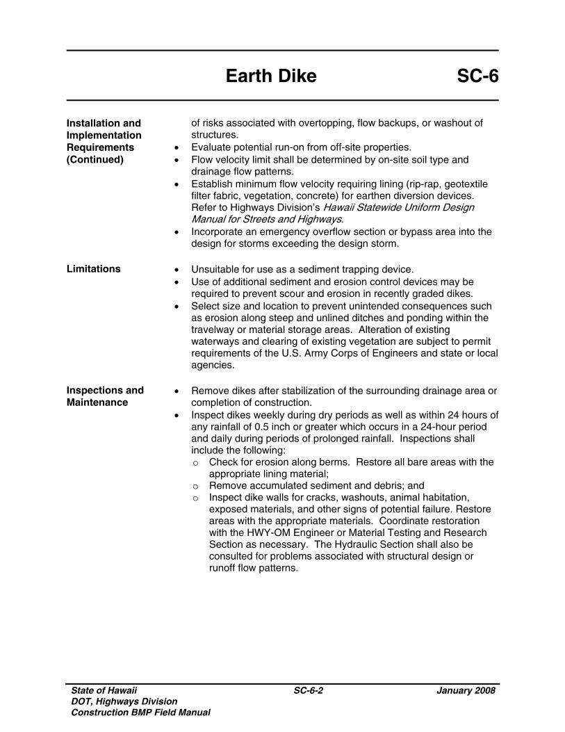
State of Hawaii DOT, Highways Division Construction BMP Field Manual
SC-6-2 January 2008
Earth Dike SC-6
Installation and Implementation Requirements (Continued)
of risks associated with overtopping, flow backups, or washout of structures.
• Evaluate potential run-on from off-site properties. • Flow velocity limit shall be determined by on-site soil type and
drainage flow patterns. • Establish minimum flow velocity requiring lining (rip-rap, geotextile
filter fabric, vegetation, concrete) for earthen diversion devices. Refer to Highways Division’s Hawaii Statewide Uniform Design Manual for Streets and Highways.
• Incorporate an emergency overflow section or bypass area into the design for storms exceeding the design storm.
Limitations • Unsuitable for use as a sediment trapping device.
• Use of additional sediment and erosion control devices may be required to prevent scour and erosion in recently graded dikes.
• Select size and location to prevent unintended consequences such as erosion along steep and unlined ditches and ponding within the travelway or material storage areas. Alteration of existing waterways and clearing of existing vegetation are subject to permit requirements of the U.S. Army Corps of Engineers and state or local agencies.
Inspections and Maintenance
• Remove dikes after stabilization of the surrounding drainage area or completion of construction.
• Inspect dikes weekly during dry periods as well as within 24 hours of any rainfall of 0.5 inch or greater which occurs in a 24-hour period and daily during periods of prolonged rainfall. Inspections shall include the following: o Check for erosion along berms. Restore all bare areas with the
appropriate lining material; o Remove accumulated sediment and debris; and o Inspect dike walls for cracks, washouts, animal habitation,
exposed materials, and other signs of potential failure. Restore areas with the appropriate materials. Coordinate restoration with the HWY-OM Engineer or Material Testing and Research Section as necessary. The Hydraulic Section shall also be consulted for problems associated with structural design or runoff flow patterns.
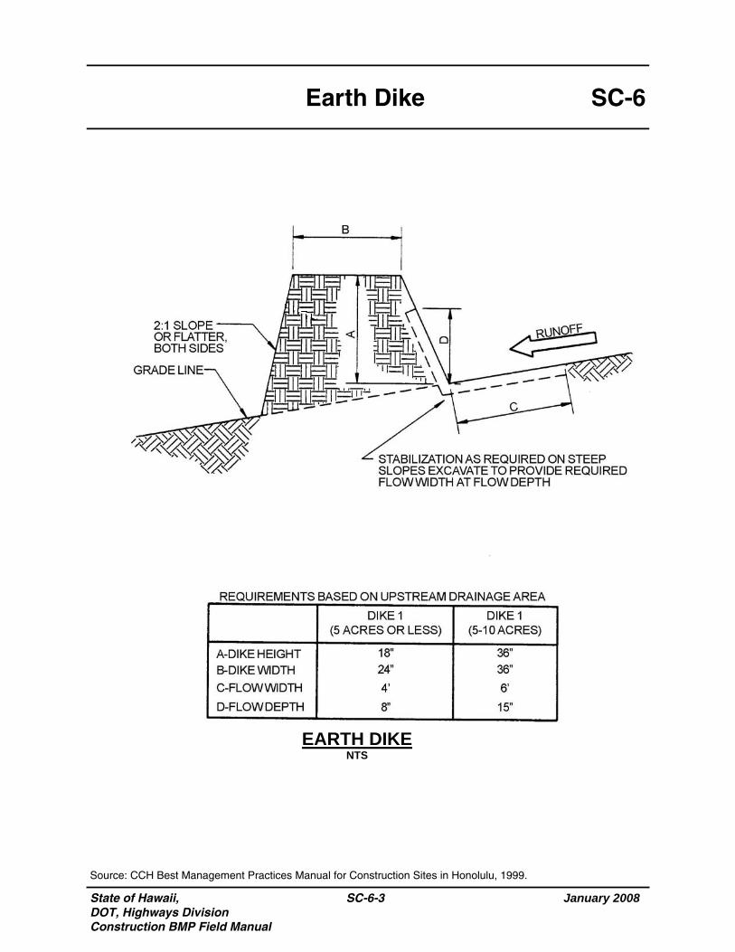
State of Hawaii, DOT, Highways Division Construction BMP Field Manual
January 2008
SC-6-3
SC-6 Earth Dike
EARTH DIKE NTS
Source: CCH Best Management Practices Manual for Construction Sites in Honolulu, 1999.
State of Hawaii DOT, Highways Division Construction BMP Field Manual
SC-6-4 January 2008
THIS PAGE INTENTIONALLY LEFT BLANK
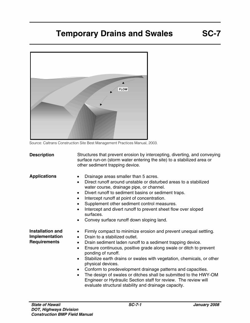
State of Hawaii DOT, Highways Division Construction BMP Field Manual
SC-7-1 January 2008
Temporary Drains and Swales SC-7
Source: Caltrans Construction Site Best Management Practices Manual, 2003.
Description Structures that prevent erosion by intercepting, diverting, and conveying surface run-on (storm water entering the site) to a stabilized area or other sediment trapping device.
Applications • Drainage areas smaller than 5 acres.
• Direct runoff around unstable or disturbed areas to a stabilized water course, drainage pipe, or channel.
• Divert runoff to sediment basins or sediment traps. • Intercept runoff at point of concentration. • Supplement other sediment control measures. • Intercept and divert runoff to prevent sheet flow over sloped
surfaces. • Convey surface runoff down sloping land.
Installation and Implementation Requirements
• Firmly compact to minimize erosion and prevent unequal settling. • Drain to a stabilized outlet. • Drain sediment laden runoff to a sediment trapping device. • Ensure continuous, positive grade along swale or ditch to prevent
ponding of runoff. • Stabilize earth drains or swales with vegetation, chemicals, or other
physical devices. • Conform to predevelopment drainage patterns and capacities. • The design of swales or ditches shall be submitted to the HWY-OM
Engineer or Hydraulic Section staff for review. The review will evaluate structural stability and drainage capacity.

State of Hawaii DOT, Highways Division Construction BMP Field Manual
SC-7-2 January 2008
Temporary Drains and Swales SC-7
Installation and Implementation Requirements (Continued)
• Design flow and safety factor shall be determined by an evaluation
of risks associated with overtopping, flow backups, or washout of structures.
• Evaluate potential run-on from off-site properties. • Flow velocity limit shall be determined by on-site soil type and
drainage flow patterns. • Establish minimum flow velocity requiring lining (rip-rap, geotextile
filter fabric, vegetation, concrete) for earthen diversion devices. Refer to Highways Division’s Hawaii Statewide Uniform Design Manual for Streets and Highways.
• Incorporate an emergency overflow section or bypass area into the design for storms exceeding the design storm.
Limitations • Unsuitable for use as a sediment trapping device.
• Use of additional sediment and erosion control devices may be required to prevent scour and erosion in recently graded swales and ditches.
• Select size and location to prevent unintended consequences such as erosion along steep and unlined ditches and ponding within the travelway or material storage areas. Alteration of existing waterways and clearing of existing vegetation are subject to permit requirements of the U.S. Army Corps of Engineers and state or local agencies.
• Ditches and swales may require check dams or lining to prevent erosion.
Inspections and Maintenance
• Remove temporary swales and ditches after stabilization of the surrounding drainage area or completion of construction.
• Inspect swales and ditches weekly during dry periods as well as within 24 hours of any rainfall of 0.5 inch or greater which occurs in a 24-hour period and daily during periods of prolonged rainfall. Inspections shall include the following: o Check for erosion along channel linings, embankments, or beds
of ditches. Restore all bare areas with the appropriate lining material;
o Remove accumulated sediment and debris; and o Inspect embankments, compacted fills, and earthen channel
sidewalls for cracks, washouts, animal habitation, exposed materials and other signs of potential failure. Restore areas with the appropriate materials. Coordinate restoration with the HWY-OM Engineer or Material Testing and Research Section as necessary. The Hydraulic Section shall also be consulted for problems associated with structural design or runoff flow patterns.
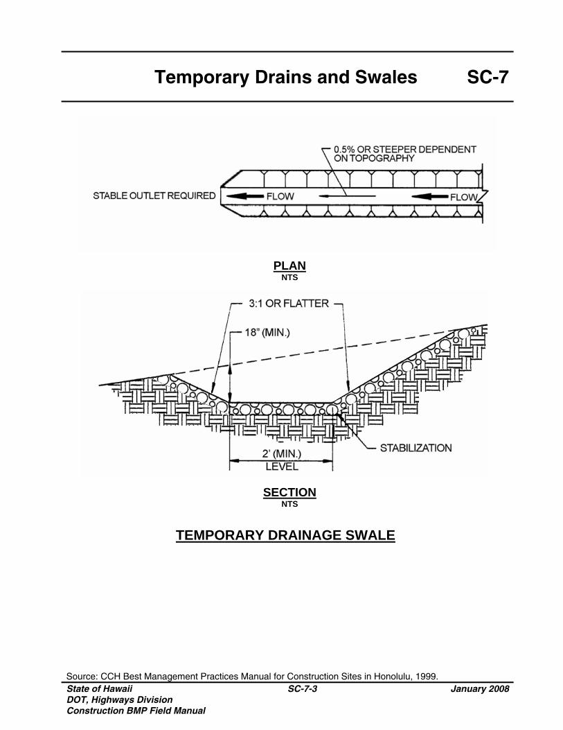
Temporary Drains and Swales SC-7
Source: CCH Best Management Practices Manual for Construction Sites in Honolulu, 1999. State of Hawaii DOT, Highways Division Construction BMP Field Manual
SC-7-3 January 2008
PLAN NTS
SECTION NTS
TEMPORARY DRAINAGE SWALE

State of Hawaii DOT, Highways Division Construction BMP Field Manual
SC-7-4 January 2008
THIS PAGE INTENTIONALLY LEFT BLANK
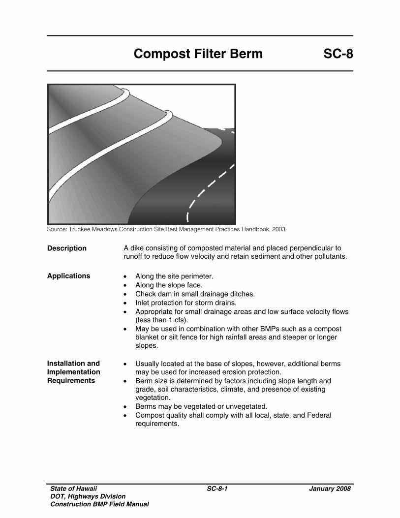
State of Hawaii DOT, Highways Division Construction BMP Field Manual
SC-8-1 January 2008
Compost Filter Berm SC-8
Source: Truckee Meadows Construction Site Best Management Practices Handbook, 2003.
Description A dike consisting of composted material and placed perpendicular to runoff to reduce flow velocity and retain sediment and other pollutants.
Applications • Along the site perimeter.
• Along the slope face. • Check dam in small drainage ditches. • Inlet protection for storm drains. • Appropriate for small drainage areas and low surface velocity flows
(less than 1 cfs). • May be used in combination with other BMPs such as a compost
blanket or silt fence for high rainfall areas and steeper or longer slopes.
Installation and Implementation Requirements
• Usually located at the base of slopes, however, additional berms may be used for increased erosion protection.
• Berm size is determined by factors including slope length and grade, soil characteristics, climate, and presence of existing vegetation.
• Berms may be vegetated or unvegetated. • Compost quality shall comply with all local, state, and Federal
requirements.
State of Hawaii DOT, Highways Division Construction BMP Field Manual
SC-8-2 January 2008
Compost Filter Berm SC-8
Installation and Implementation Requirements (Continued)
• Installation of a compost filter sock, which consists of a mesh tube filled with composted material, as a type of compost filter berm shall comply with the following: o Assemble by tying a knot at one end of the mesh sock, filling
the sock with compost, and knotting the other end of the sock. A pneumatic blower may be used to fill the sock with compost;
o Use a filter sock equivalent to the length of the slope where practicable;
o When use of multiple socks is required, place socks end-to-end and interlock the ends;
o Anchor filter socks to ground; and o Turn ends of filter sock up slope to prevent flow around ends.
• Material for compost berm may be left at the site and used as a soil amendment.
• Mesh socks filled with compost may also be used for areas of concentrated flow such as near streams or shorelines.
Limitations • Unsuitable for areas with concentrated runoff unless a low flow rate
and small drainage area warrants use of a filter berm. • Heavy vegetation must be removed to ensure close contact of
compost with the ground surface. Inspections and Maintenance
• Inspect weekly during dry periods as well as within 24 hours of any rainfall of 0.5 inch or greater which occurs in a 24-hour period and daily during periods of prolonged rainfall.
• Remove sediment which has accumulated to within 1/3 of the berm height.
• Replace disturbed or damaged areas of the berm. • Significant washout may indicate a larger berm or additional BMPs
such as a compost blanket or silt fence are required.
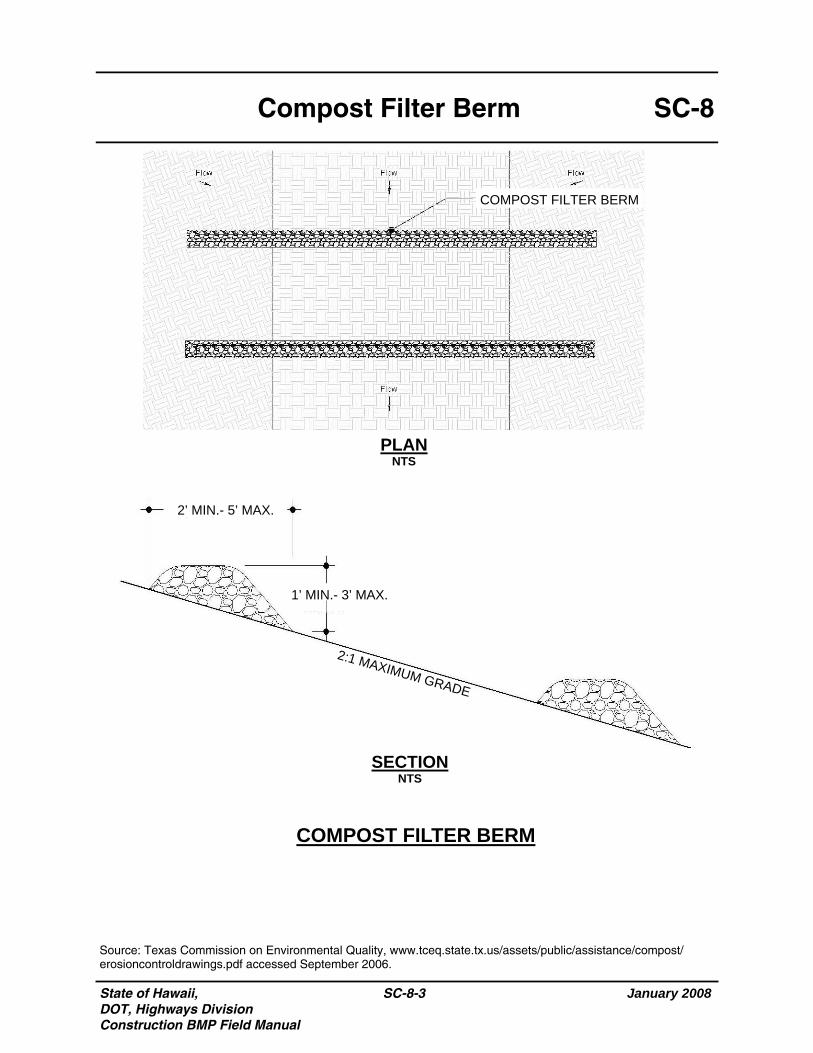
State of Hawaii, DOT, Highways Division Construction BMP Field Manual
January 2008
SC-8-3
SC-8 Compost Filter Berm
Source: Texas Commission on Environmental Quality, www.tceq.state.tx.us/assets/public/assistance/compost/erosioncontroldrawings.pdf accessed September 2006.
COMPOST FILTER BERM
PLAN NTS
SECTION NTS
1’ MIN.- 3’ MAX.
2’ MIN.- 5’ MAX.
COMPOST FILTER BERM
2:1 MAXIMUM GRADE
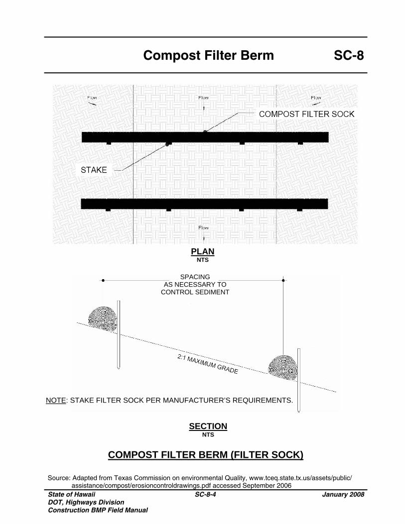
Compost Filter Berm SC-8
Source: Adapted from Texas Commission on environmental Quality, www.tceq.state.tx.us/assets/public/ assistance/compost/erosioncontroldrawings.pdf accessed September 2006 State of Hawaii DOT, Highways Division Construction BMP Field Manual
SC-8-4 January 2008
PLAN NTS
SECTION NTS
COMPOST FILTER BERM (FILTER SOCK)
NOTE: STAKE FILTER SOCK PER MANUFACTURER’S REQUIREMENTS.
SPACING AS NECESSARY TO
CONTROL SEDIMENT
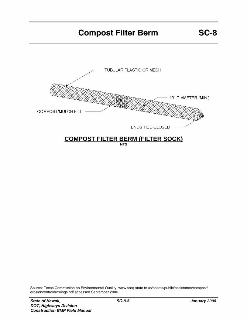
State of Hawaii, DOT, Highways Division Construction BMP Field Manual
January 2008
SC-8-5
SC-8 Compost Filter Berm
Source: Texas Commission on Environmental Quality, www.tceq.state.tx.us/assets/public/assistance/compost/erosioncontroldrawings.pdf accessed September 2006.
COMPOST FILTER BERM (FILTER SOCK) NTS

State of Hawaii DOT, Highways Division Construction BMP Field Manual
SC-8-6 January 2008
THIS PAGE INTENTIONALLY LEFT BLANK
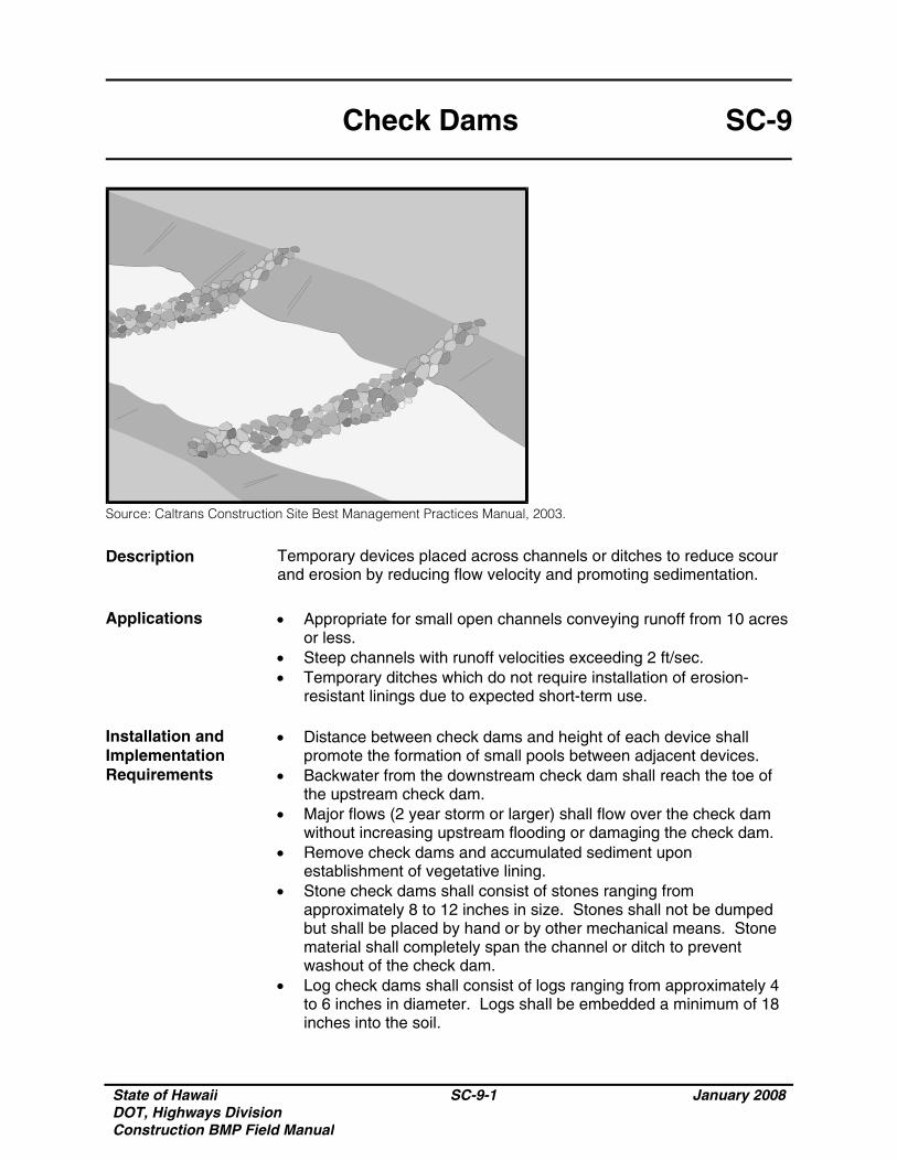
State of Hawaii DOT, Highways Division Construction BMP Field Manual
SC-9-1 January 2008
Check Dams SC-9
Source: Caltrans Construction Site Best Management Practices Manual, 2003.
Description Temporary devices placed across channels or ditches to reduce scour and erosion by reducing flow velocity and promoting sedimentation.
Applications • Appropriate for small open channels conveying runoff from 10 acres
or less. • Steep channels with runoff velocities exceeding 2 ft/sec. • Temporary ditches which do not require installation of erosion-
resistant linings due to expected short-term use. Installation and Implementation Requirements
• Distance between check dams and height of each device shall promote the formation of small pools between adjacent devices.
• Backwater from the downstream check dam shall reach the toe of the upstream check dam.
• Major flows (2 year storm or larger) shall flow over the check dam without increasing upstream flooding or damaging the check dam.
• Remove check dams and accumulated sediment upon establishment of vegetative lining.
• Stone check dams shall consist of stones ranging from approximately 8 to 12 inches in size. Stones shall not be dumped but shall be placed by hand or by other mechanical means. Stone material shall completely span the channel or ditch to prevent washout of the check dam.
• Log check dams shall consist of logs ranging from approximately 4 to 6 inches in diameter. Logs shall be embedded a minimum of 18 inches into the soil.
State of Hawaii DOT, Highways Division Construction BMP Field Manual
SC-9-2 January 2008
Check Dams SC-9
Installation and Implementation Requirements (Continued)
• Remove check dams upon establishment of grass used for stabilization of the ditch or channel, unless the slope of the swale exceeds 4 percent.
Limitations • Drainage area discharging to open channels shall not exceed 10
acres. • Not applicable to live streams. • Not applicable to channels with established grass linings unless
erosion is expected since check dam installation may damage existing vegetation.
• High velocity flows may require extensive maintenance. • Subsequent storms or removal of the check dam may re-suspend
trapped sediment. Inspections and Maintenance
• Inspect check dams for sediment accumulation and erosion weekly during dry periods as well as within 24 hours of any rainfall of 0.5 inch or greater which occurs in a 24-hour period and daily during periods of prolonged rainfall.
• Remove accumulated sediment when depth reaches one-half the sump depth.
• Prior to permanent seeding or soil stabilization, remove accumulated sediment and check dams.
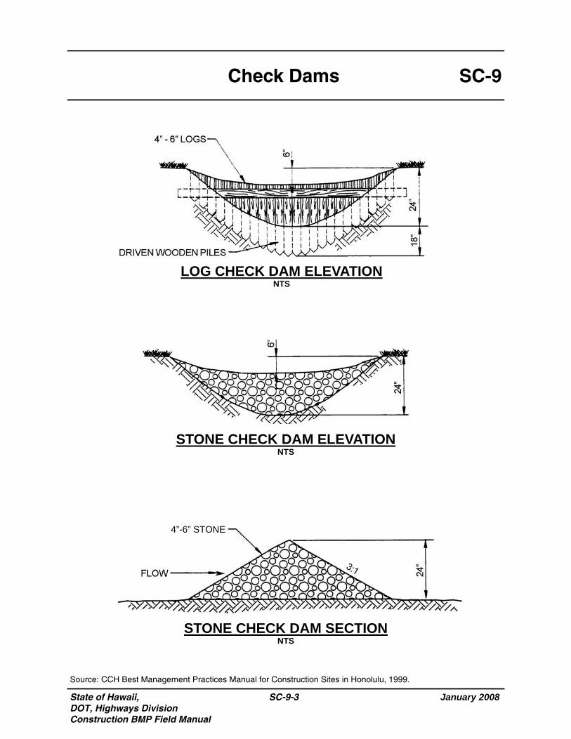
State of Hawaii, DOT, Highways Division Construction BMP Field Manual
January 2008
SC-9-3
SC-9 Check Dams
STONE CHECK DAM SECTION NTS
STONE CHECK DAM ELEVATION NTS
LOG CHECK DAM ELEVATION NTS
Source: CCH Best Management Practices Manual for Construction Sites in Honolulu, 1999.
4”-6” STONE
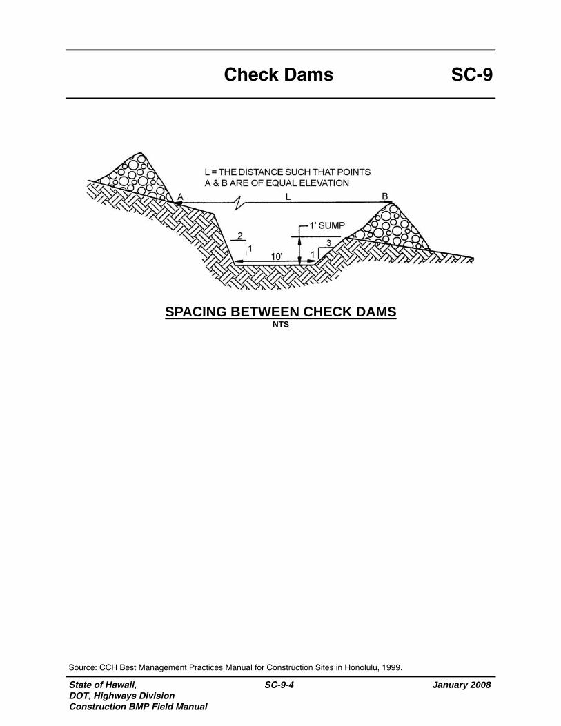
State of Hawaii, DOT, Highways Division Construction BMP Field Manual
January 2008
SC-9-4
SC-9 Check Dams
SPACING BETWEEN CHECK DAMS NTS
Source: CCH Best Management Practices Manual for Construction Sites in Honolulu, 1999.
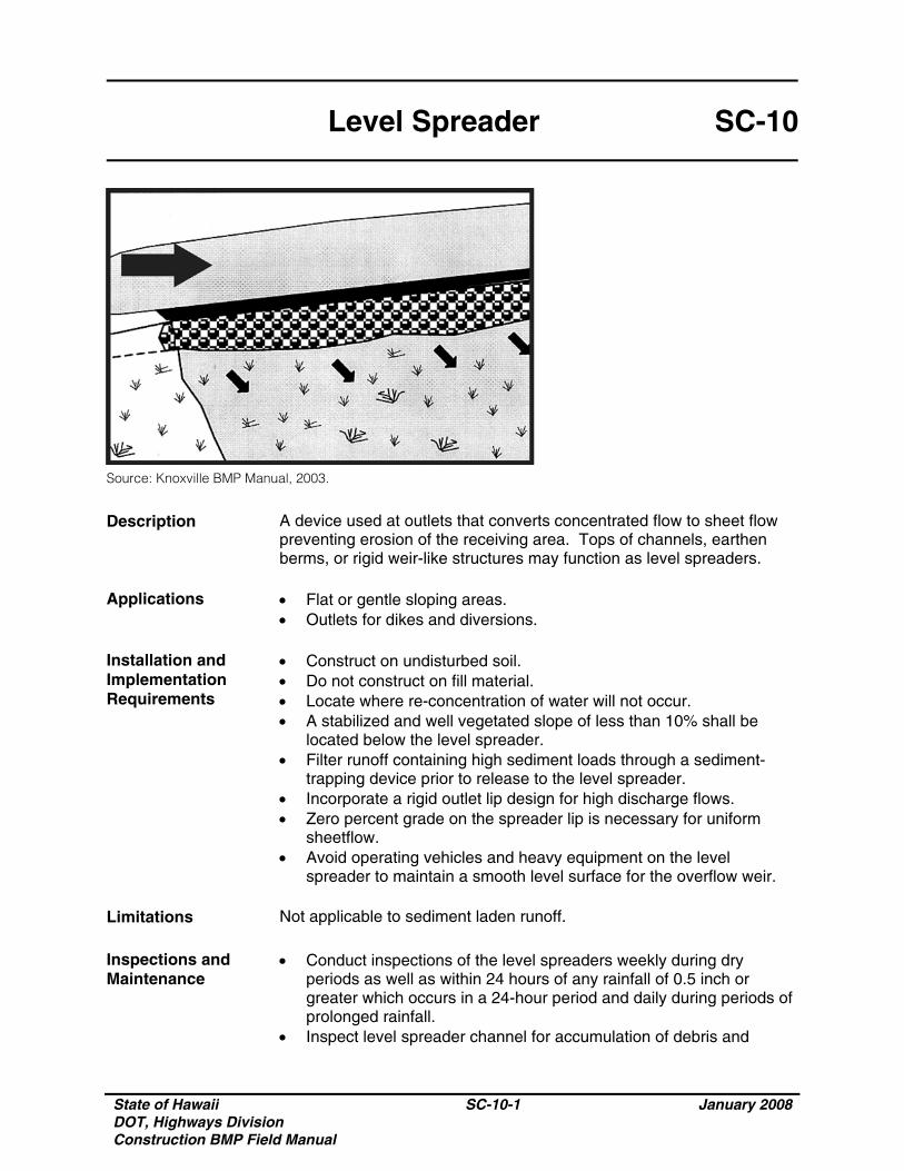
State of Hawaii DOT, Highways Division Construction BMP Field Manual
SC-10-1 January 2008
Level Spreader SC-10
Source: Knoxville BMP Manual, 2003.
Description A device used at outlets that converts concentrated flow to sheet flow preventing erosion of the receiving area. Tops of channels, earthen berms, or rigid weir-like structures may function as level spreaders.
Applications • Flat or gentle sloping areas.
• Outlets for dikes and diversions. Installation and Implementation Requirements
• Construct on undisturbed soil. • Do not construct on fill material. • Locate where re-concentration of water will not occur. • A stabilized and well vegetated slope of less than 10% shall be
located below the level spreader. • Filter runoff containing high sediment loads through a sediment-
trapping device prior to release to the level spreader. • Incorporate a rigid outlet lip design for high discharge flows. • Zero percent grade on the spreader lip is necessary for uniform
sheetflow. • Avoid operating vehicles and heavy equipment on the level
spreader to maintain a smooth level surface for the overflow weir. Limitations Not applicable to sediment laden runoff. Inspections and Maintenance
• Conduct inspections of the level spreaders weekly during dry periods as well as within 24 hours of any rainfall of 0.5 inch or greater which occurs in a 24-hour period and daily during periods of prolonged rainfall.
• Inspect level spreader channel for accumulation of debris and
State of Hawaii DOT, Highways Division Construction BMP Field Manual
SC-10-2 January 2008
Level Spreader SC-10
Inspections and Maintenance (Continued)
sediment regularly and remove debris and sediment. • Verify a slope of zero percent along the spreader lip. • Inspect the discharge area for signs of erosion or concentrated flow.
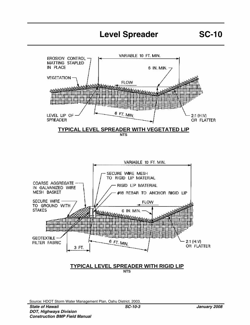
Level Spreader SC-10
Source: HDOT Storm Water Management Plan, Oahu District, 2003. State of Hawaii DOT, Highways Division Construction BMP Field Manual
SC-10-3 January 2008
TYPICAL LEVEL SPREADER WITH VEGETATED LIP NTS
TYPICAL LEVEL SPREADER WITH RIGID LIP
NTS

State of Hawaii DOT, Highways Division Construction BMP Field Manual
SC-10-4 January 2008
THIS PAGE INTENTIONALLY LEFT BLANK
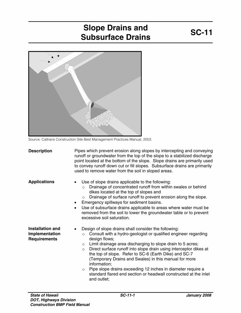
State of Hawaii DOT, Highways Division Construction BMP Field Manual
SC-11-1 January 2008
Slope Drains and Subsurface Drains
SC-11
Source: Caltrans Construction Site Best Management Practices Manual, 2003.
Description Pipes which prevent erosion along slopes by intercepting and conveying runoff or groundwater from the top of the slope to a stabilized discharge point located at the bottom of the slope. Slope drains are primarily used to convey runoff down cut or fill slopes. Subsurface drains are primarily used to remove water from the soil in sloped areas.
Applications • Use of slope drains applicable to the following:
o Drainage of concentrated runoff from within swales or behind dikes located at the top of slopes and
o Drainage of surface runoff to prevent erosion along the slope. • Emergency spillways for sediment basins. • Use of subsurface drains applicable to areas where water must be
removed from the soil to lower the groundwater table or to prevent excessive soil saturation.
Installation and Implementation Requirements
• Design of slope drains shall consider the following: o Consult with a hydro-geologist or qualified engineer regarding
design flows; o Limit drainage area discharging to slope drain to 5 acres; o Direct surface runoff into slope drain using interceptor dikes at
the top of slope. Refer to SC-6 (Earth Dike) and SC-7 (Temporary Drains and Swales) in this manual for more information;
o Pipe slope drains exceeding 12 inches in diameter require a standard flared end section or headwall constructed at the inlet and outlet;
State of Hawaii DOT, Highways Division Construction BMP Field Manual
SC-11-2 January 2008
Slope Drains and Subsurface Drains
SC-11
Installation and Implementation Requirements (Continued)
o Install lining such as vegetation or geotextile filter fabric to protect area around inlet;
o Install rip-rap or other energy dissipation device at outlets; o Compact soil under and around inlet, outlet, and along the pipe;o Slope drains may be installed above ground or buried beneath
the slope surface; o Above ground installation shall utilize pipe anchors to secure
pipe to ground; o Align slope drain perpendicular to contours of slope; o Generally limit maximum slope to 2:1 (H:V). For slopes
exceeding 2:1 (H:V), velocity dissipation is required at the pipe outlet; and
o Direct sediment-laden stormwater to a sediment trap or sediment basin.
Limitations • Drainage area discharging to slope drains shall not exceed 5 acres.
For larger areas, use multiple pipes, paved chute, or rock lined channel.
• Clogged slope drains direct runoff around pipe which may result in erosion along the slope.
• High flow velocities at the pipe outlet require implementation of velocity dissipation devices to prevent downstream erosion.
• Severe flooding and erosion may result from failure of slope drains. Inspections and Maintenance
• Inspect weekly during dry periods as well as within 24 hours of any rainfall of 0.5 inch or greater which occurs in a 24-hour period and daily during periods of prolonged rainfall for erosion at outlet and downstream scour. Repair damage and install energy dissipation devices as necessary.
• Inspect slope drains for debris and sediment accumulation. Remove sediment and debris from entrances, outlets, and within drains.
• Inspect pipe anchors to ensure pipe remains anchored to slope. • Verify ponding does not occur in areas such as active traffic lanes
and material storage areas.

State of Hawaii, DOT, Highways Division Construction BMP Field Manual
January 2008
SC-11-3
SC-11 Slope Drains and
Subsurface Drains
Source: CCH Best Management Practices Manual for Construction Sites in Honolulu, 1999.
PIPE SLOPE DRAIN (RIGID) NTS
RIP-RAP
RIGID PIPE
RIP-RAP
RIP-RAP
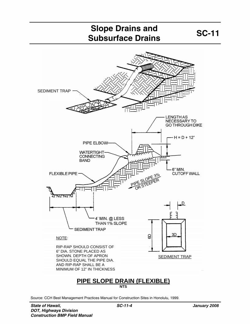
State of Hawaii, DOT, Highways Division Construction BMP Field Manual
January 2008
SC-11-4
SC-11 Slope Drains and
Subsurface Drains
Source: CCH Best Management Practices Manual for Construction Sites in Honolulu, 1999.
PIPE SLOPE DRAIN (FLEXIBLE) NTS
SEDIMENT TRAP
SEDIMENT TRAP RIP-RAP
NOTE: RIP-RAP SHOULD CONSIST OF 6” DIA. STONE PLACED AS SHOWN. DEPTH OF APRON SHOULD EQUAL THE PIPE DIA. AND RIP-RAP SHALL BE A MINIMUM OF 12” IN THICKNESS
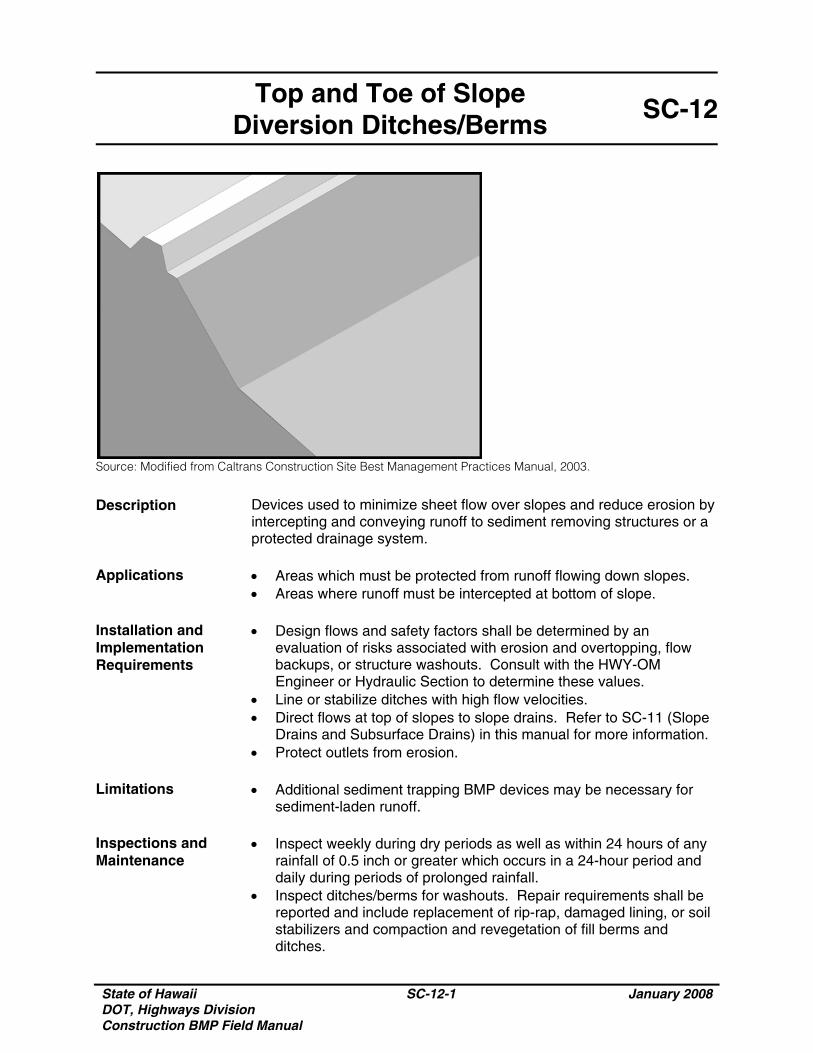
State of Hawaii DOT, Highways Division Construction BMP Field Manual
SC-12-1 January 2008
Top and Toe of Slope Diversion Ditches/Berms
SC-12
Source: Modified from Caltrans Construction Site Best Management Practices Manual, 2003.
Description Devices used to minimize sheet flow over slopes and reduce erosion by intercepting and conveying runoff to sediment removing structures or a protected drainage system.
Applications • Areas which must be protected from runoff flowing down slopes.
• Areas where runoff must be intercepted at bottom of slope. Installation and Implementation Requirements
• Design flows and safety factors shall be determined by an evaluation of risks associated with erosion and overtopping, flow backups, or structure washouts. Consult with the HWY-OM Engineer or Hydraulic Section to determine these values.
• Line or stabilize ditches with high flow velocities. • Direct flows at top of slopes to slope drains. Refer to SC-11 (Slope
Drains and Subsurface Drains) in this manual for more information. • Protect outlets from erosion.
Limitations • Additional sediment trapping BMP devices may be necessary for
sediment-laden runoff. Inspections and Maintenance
• Inspect weekly during dry periods as well as within 24 hours of any rainfall of 0.5 inch or greater which occurs in a 24-hour period and daily during periods of prolonged rainfall.
• Inspect ditches/berms for washouts. Repair requirements shall be reported and include replacement of rip-rap, damaged lining, or soil stabilizers and compaction and revegetation of fill berms and ditches.
State of Hawaii DOT, Highways Division Construction BMP Field Manual
SC-12-2 January 2008
Top and Toe of Slope Diversion Ditches/Berms
SC-12
Inspections and Maintenance (Continued)
• Inspect structures for accumulated sediment and debris and remove
as necessary.
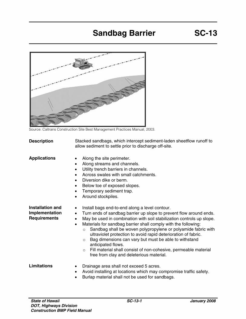
State of Hawaii DOT, Highways Division Construction BMP Field Manual
SC-13-1 January 2008
Sandbag Barrier SC-13
Source: Caltrans Construction Site Best Management Practices Manual, 2003.
Description Stacked sandbags, which intercept sediment-laden sheetflow runoff to allow sediment to settle prior to discharge off-site.
Applications • Along the site perimeter.
• Along streams and channels. • Utility trench barriers in channels. • Across swales with small catchments. • Diversion dike or berm. • Below toe of exposed slopes. • Temporary sediment trap. • Around stockpiles.
Installation and Implementation Requirements
• Install bags end-to-end along a level contour. • Turn ends of sandbag barrier up slope to prevent flow around ends. • May be used in combination with soil stabilization controls up slope. • Materials for sandbag barrier shall comply with the following:
o Sandbag shall be woven polypropylene or polyamide fabric with ultraviolet protection to avoid rapid deterioration of fabric.
o Bag dimensions can vary but must be able to withstand anticipated flows.
o Fill material shall consist of non-cohesive, permeable material free from clay and deleterious material.
Limitations
• Drainage area shall not exceed 5 acres. • Avoid installing at locations which may compromise traffic safety. • Burlap material shall not be used for sandbags.
State of Hawaii DOT, Highways Division Construction BMP Field Manual
SC-13-2 January 2008
Sandbag Barrier SC-13
Inspections and Maintenance
• Inspect weekly during dry periods as well as within 24 hours of any rainfall of 0.5 inch or greater which occurs in a 24-hour period and daily during periods of prolonged rainfall.
• Reshape or replace sandbags as necessary. • Remove and properly dispose of sediment, which has accumulated
to a depth of 6 inches.
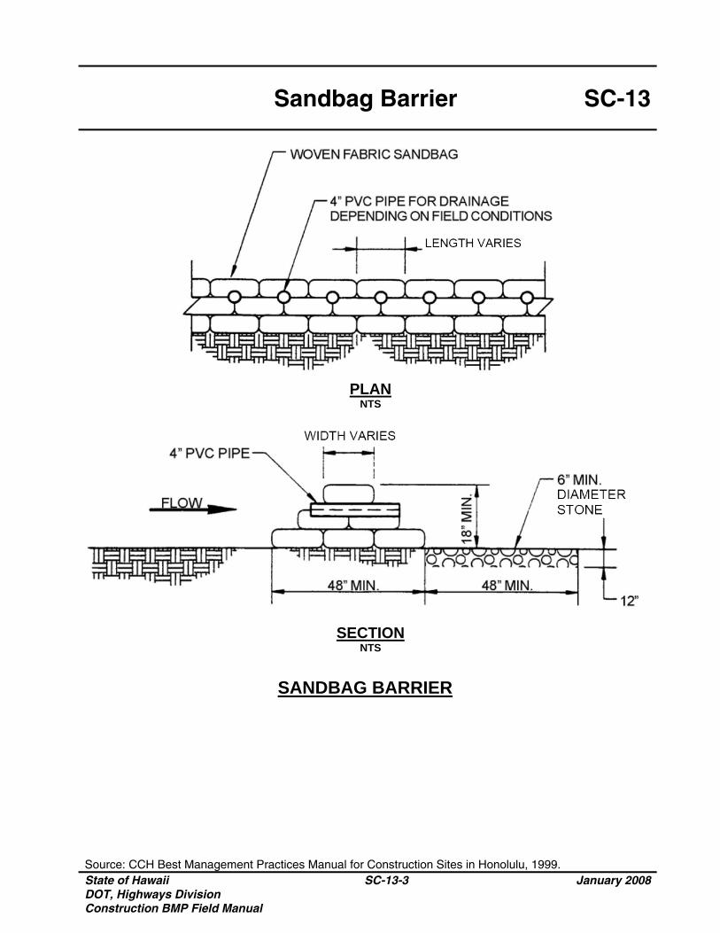
Sandbag Barrier SC-13
Source: CCH Best Management Practices Manual for Construction Sites in Honolulu, 1999. State of Hawaii DOT, Highways Division Construction BMP Field Manual
SC-13-3 January 2008
PLAN NTS
SECTION NTS
SANDBAG BARRIER

State of Hawaii DOT, Highways Division Construction BMP Field Manual
SC-13-4 January 2008
THIS PAGE INTENTIONALLY LEFT BLANK
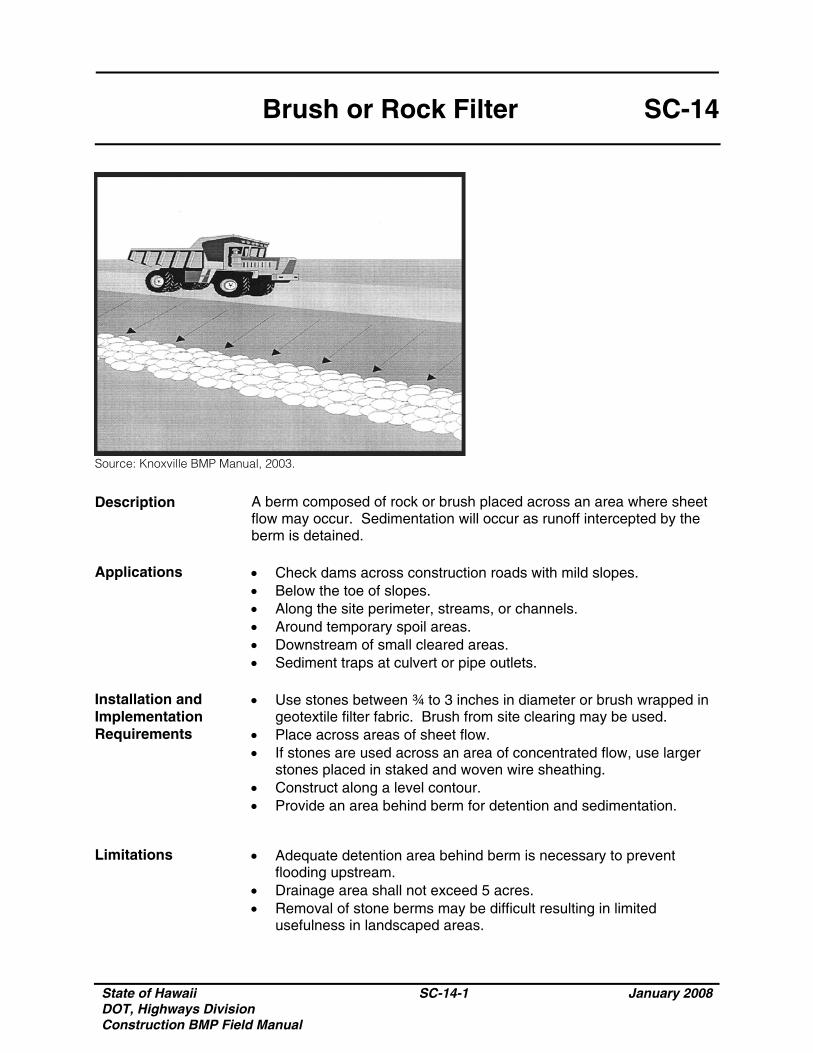
State of Hawaii DOT, Highways Division Construction BMP Field Manual
SC-14-1 January 2008
Brush or Rock Filter SC-14
Source: Knoxville BMP Manual, 2003.
Description A berm composed of rock or brush placed across an area where sheet flow may occur. Sedimentation will occur as runoff intercepted by the berm is detained.
Applications • Check dams across construction roads with mild slopes.
• Below the toe of slopes. • Along the site perimeter, streams, or channels. • Around temporary spoil areas. • Downstream of small cleared areas. • Sediment traps at culvert or pipe outlets.
Installation and Implementation Requirements
• Use stones between ¾ to 3 inches in diameter or brush wrapped in geotextile filter fabric. Brush from site clearing may be used.
• Place across areas of sheet flow. • If stones are used across an area of concentrated flow, use larger
stones placed in staked and woven wire sheathing. • Construct along a level contour. • Provide an area behind berm for detention and sedimentation.
Limitations • Adequate detention area behind berm is necessary to prevent
flooding upstream. • Drainage area shall not exceed 5 acres. • Removal of stone berms may be difficult resulting in limited
usefulness in landscaped areas.
State of Hawaii DOT, Highways Division Construction BMP Field Manual
SC-14-2 January 2008
Brush or Rock Filter SC-14
Inspections and Maintenance
• Inspect weekly during dry periods as well as within 24 hours of any rainfall of 0.5 inch or greater which occurs in a 24-hour period and daily during periods of prolonged rainfall.
• Reshape berm and replace any missing or dislodged stone or brush.• Remove and dispose of sediment on upstream side of filter upon
reaching a depth of six inches.
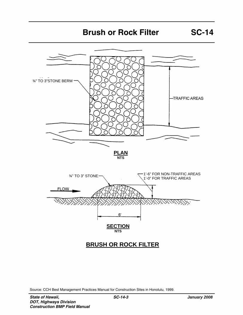
State of Hawaii, DOT, Highways Division Construction BMP Field Manual
January 2008
SC-14-3
SC-14 Brush or Rock Filter
Source: CCH Best Management Practices Manual for Construction Sites in Honolulu, 1999.
BRUSH OR ROCK FILTER
PLAN NTS
SECTION NTS
1’-6” FOR NON-TRAFFIC AREAS 1’-0” FOR TRAFFIC AREAS ¾” TO 3” STONE
¾” TO 3”STONE BERM

State of Hawaii DOT, Highways Division Construction BMP Field Manual
SC-14-4 January 2008
THIS PAGE INTENTIONALLY LEFT BLANK
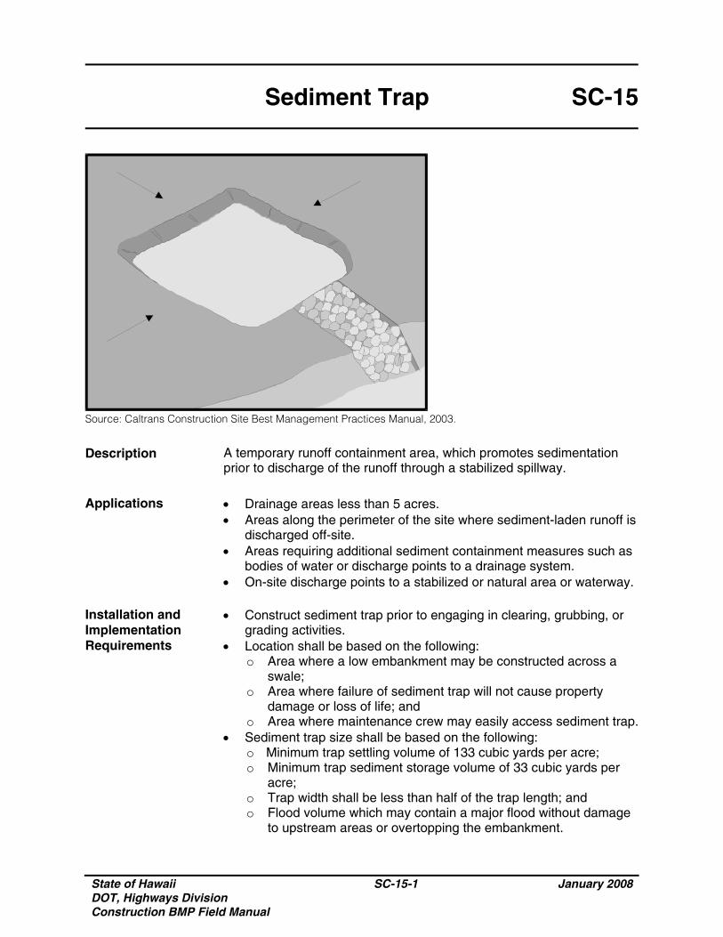
State of Hawaii DOT, Highways Division Construction BMP Field Manual
SC-15-1 January 2008
Sediment Trap SC-15
Source: Caltrans Construction Site Best Management Practices Manual, 2003.
Description A temporary runoff containment area, which promotes sedimentation prior to discharge of the runoff through a stabilized spillway.
Applications • Drainage areas less than 5 acres.
• Areas along the perimeter of the site where sediment-laden runoff is discharged off-site.
• Areas requiring additional sediment containment measures such as bodies of water or discharge points to a drainage system.
• On-site discharge points to a stabilized or natural area or waterway. Installation and Implementation Requirements
• Construct sediment trap prior to engaging in clearing, grubbing, or grading activities.
• Location shall be based on the following: o Area where a low embankment may be constructed across a
swale; o Area where failure of sediment trap will not cause property
damage or loss of life; and o Area where maintenance crew may easily access sediment trap.
• Sediment trap size shall be based on the following: o Minimum trap settling volume of 133 cubic yards per acre; o Minimum trap sediment storage volume of 33 cubic yards per
acre; o Trap width shall be less than half of the trap length; and o Flood volume which may contain a major flood without damage
to upstream areas or overtopping the embankment.
State of Hawaii DOT, Highways Division Construction BMP Field Manual
SC-15-2 January 2008
Sediment Trap SC-15
Installation and Implementation Requirements (Continued)
• Construct sediment trap by excavating ground or constructing an earthen embankment to create a containment area.
• Area under embankment shall be cleared, grubbed, and stripped of vegetation and root mat.
• Fill material for embankment shall be free of roots, woody vegetation, over-sized stones, rocks, organic material, or other objectionable material. Compact embankment by traversing with construction equipment.
• Stabilize trap outlet with stone or vegetation. • Install fencing to prevent unauthorized entry and for safety
purposes. • All pipe joints shall be watertight when a riser is used. • The top 2/3 of the riser shall be perforated with holes 1 to 4 inch in
diameter. The holes shall be vertically spaced at 8 inch intervals and horizontally spaced at 10 to 12 inch intervals.
• Outlet crest elevation of an earth or stone outlet shall be a minimum of 1 foot below the top of the embankment.
Limitations • Applies to maximum drainage area of 5 acres. Drainage areas
exceeding 5 acres shall implement Sediment Basins. Refer to SC-16 (Sediment Basin) in this manual for more information.
• Only removes large and medium size particles. • Requires protective fencing. • Do not install in live streams. • Availability of right-of-way may limit size of sediment trap.
Inspections and Maintenance
• Inspect weekly during dry periods as well as within 24 hours of any rainfall of 0.5 inch or greater which occurs in a 24-hour period and daily during periods of prolonged rainfall.
• Inspect spillway and outlet for obstructions or damage. Remove obstructions and repair damage as necessary.
• Inspect outlet for erosion and stabilize as necessary. • Inspect fencing for damage and repair as necessary. • Remove sediment which has accumulated to within 1 foot of the top
of the dry storage volume. • Properly dispose of sediment and debris removed from sediment
trap.
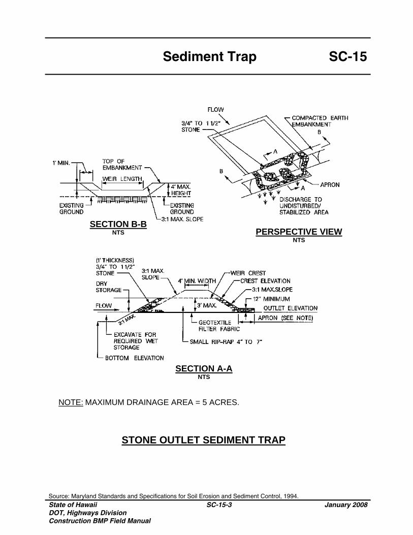
Sediment Trap SC-15
Source: Maryland Standards and Specifications for Soil Erosion and Sediment Control, 1994. State of Hawaii DOT, Highways Division Construction BMP Field Manual
SC-15-3 January 2008
SECTION B-B NTS PERSPECTIVE VIEW
NTS
SECTION A-A NTS
STONE OUTLET SEDIMENT TRAP
NOTE: MAXIMUM DRAINAGE AREA = 5 ACRES.
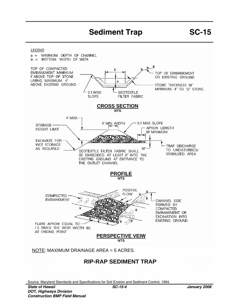
Sediment Trap SC-15
Source: Maryland Standards and Specifications for Soil Erosion and Sediment Control, 1994. State of Hawaii DOT, Highways Division Construction BMP Field Manual
SC-15-4 January 2008
CROSS SECTION NTS
PROFILE NTS
PERSPECTIVE VEIW NTS
NOTE: MAXIMUM DRAINAGE AREA = 5 ACRES.
RIP-RAP SEDIMENT TRAP
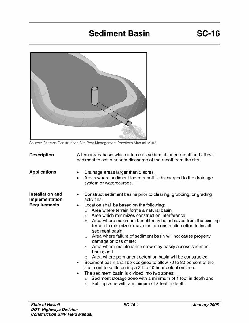
State of Hawaii DOT, Highways Division Construction BMP Field Manual
SC-16-1 January 2008
Sediment Basin SC-16
Source: Caltrans Construction Site Best Management Practices Manual, 2003.
Description A temporary basin which intercepts sediment-laden runoff and allows sediment to settle prior to discharge of the runoff from the site.
Applications • Drainage areas larger than 5 acres.
• Areas where sediment-laden runoff is discharged to the drainage system or watercourses.
Installation and Implementation Requirements
• Construct sediment basins prior to clearing, grubbing, or grading activities.
• Location shall be based on the following: o Area where terrain forms a natural basin; o Area which minimizes construction interference; o Area where maximum benefit may be achieved from the existing
terrain to minimize excavation or construction effort to install sediment basin;
o Area where failure of sediment basin will not cause property damage or loss of life;
o Area where maintenance crew may easily access sediment basin; and
o Area where permanent detention basin will be constructed. • Sediment basin shall be designed to allow 70 to 80 percent of the
sediment to settle during a 24 to 40 hour detention time. • The sediment basin is divided into two zones:
o Sediment storage zone with a minimum of 1 foot in depth and o Settling zone with a minimum of 2 feet in depth
State of Hawaii DOT, Highways Division Construction BMP Field Manual
SC-16-2 January 2008
Sediment Basin SC-16
Installation and Implementation Requirements (Continued)
• Sediment basin design shall be based on the following requirements: o Settling zone volume shall be determined by the following
equation: V=1.2(SD)Q/VSED
Where: V =Settling zone volume SD =Settling depth, which shall be a minimum of 2 feet and
greater than the average distance from inlet to outlet of the basin divided by 200
VSED=Settling velocity of the design soil particle (medium silt). The settling velocity of a medium silt soil particle is 0.00096 feet per second
Q =CIA Where: Q =Discharge rate measured in cubic feet per second C =Runoff coefficient I =Precipitation intensity for the 10 year, 1 hour rain event A =Area draining into the sediment basin in acres;
o Basin geometry for the sediment storage zone shall be determined by a minimum depth of 1 foot and 3:1or flatter side slopes extending from the bottom of the basin. Basin bottom shall be level;
o Provide an emergency spillway with the top of the riser pipe 1 foot below the crest elevation;
o Sediment basin length to settling depth ratio (L/SD) shall not exceed 200; and
o Sediment basin length to width ratio shall not be less than 6:1 or baffles shall be installed.
• Anti-seep collar shall be securely anchored and installed on the outlet pipe/riser.
• Construct sediment basin by excavating ground or constructing an embankment of compacted soil.
• Sediment basin may have more than one inflow point. • Stabilize inlet, outlet, and slopes of basin with rock or vegetation. • Install fencing to prevent unauthorized entry and for safety
purposes. Limitations
• Limited design life of 12 to 18 months. • Sediment basin removes medium size particles. • Additional BMPs such as seeding, mulching, and diversion dikes
may be used to reduce the amount of sediment intercepted by the basin.
State of Hawaii DOT, Highways Division Construction BMP Field Manual
SC-16-3 January 2008
Sediment Basin SC-16
Limitations (Continued)
• Requires protective fencing. • Inappropriate for installation in live streams. • Availability of right-of-way may limit size of sediment basin. • Large basins may be subject to state/local requirements for dam
safety. Inspections and Maintenance
• Inspect weekly during dry periods as well as within 24 hours of any rainfall of 0.5 inch or greater which occurs in a 24-hour period and daily during periods of prolonged rainfall.
• Inspect inlet and outlet for obstructions or damage. Remove obstructions and repair damage as necessary.
• Inspect outlet for erosion and stabilize as necessary. • Inspect fencing for damage and repair as necessary • Remove sediment when the sediment storage volume is half full. • Properly dispose of sediment and debris removed from sediment
basin.
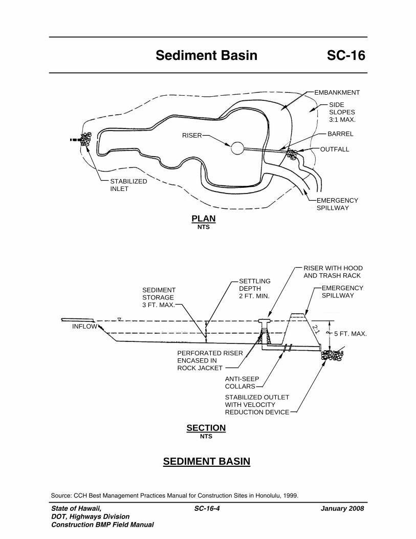
State of Hawaii, DOT, Highways Division Construction BMP Field Manual
January 2008
SC-16-4
SC-16 Sediment Basin
Source: CCH Best Management Practices Manual for Construction Sites in Honolulu, 1999.
SEDIMENT BASIN
PLAN NTS
SECTION NTS
STABILIZED INLET
RISER
EMERGENCY SPILLWAY
EMBANKMENT
SIDE SLOPES 3:1 MAX.
BARREL
OUTFALL
INFLOW
PERFORATED RISER ENCASED IN ROCK JACKET
5 FT. MAX.
2:1
EMERGENCY SPILLWAY
RISER WITH HOOD AND TRASH RACK
ANTI-SEEP COLLARS
SETTLING DEPTH 2 FT. MIN.
SEDIMENT STORAGE 3 FT. MAX.
STABILIZED OUTLET WITH VELOCITY REDUCTION DEVICE