considering temperature applications in wellbore...
TRANSCRIPT

NeoTek Confidential – No disclosure without prior written permission
Considering Temperature Applications In Wellbore Analysis
May, 2015
1
5/29/2015

NeoTek Confidential – No disclosure without prior written permissionNeoTek Confidential – No disclosure without prior written permission
Wellbore Analysis
Purpose
• Meet your objectives !
Differentiators
• Service Provider should be objective oriented.
• Should be measured by your success understanding wellbore dynamics.
• Must understand the ability and limitations of downhole equipment:
– Is the equipment engineered for wellbore diameters and environments –
Temperatures, Pressures, and Chemicals that may be present.
Logging Services
It is critical to:
• Define the test objective
• Develop logging procedure
• Prepare necessary equipment
• Conduct pre-deployment meeting with team
• Perform site specific and job safety analysis
Once the job is complete, timely log presentation with the analysis and interpretation
is important.

NeoTek Confidential – No disclosure without prior written permissionNeoTek Confidential – No disclosure without prior written permission
Typical Wellbore Analysis Applications
Locate leaks in tubing, casing, or packers
Find cross flow between zones
Locate channeling behind pipe
Quantify production or injection rates of each interval
Locate water entry and determine if it is coming from the pay zone
or channeling from above or below
Find non-performing perforations
Evaluate gas-lift performance
Locate storage of injection or fracture fluids

NeoTek Confidential – No disclosure without prior written permissionNeoTek Confidential – No disclosure without prior written permission
Example of Log Analysis Provided to Oil Producers
5/29/2015 4
Typical data and analysis from a
production log. Both spinner (flow
velocity) and density (fluid weight)
have serious limitations and yet
these are used to determine
production rates. The industry to
this day uses physical
measurements to calculate
chemical composition.
Reasonable accuracy difficult in
multiphase flow.
NeoTek Confidential – No disclosure without prior written permissionNeoTek Confidential – No disclosure without prior written permission
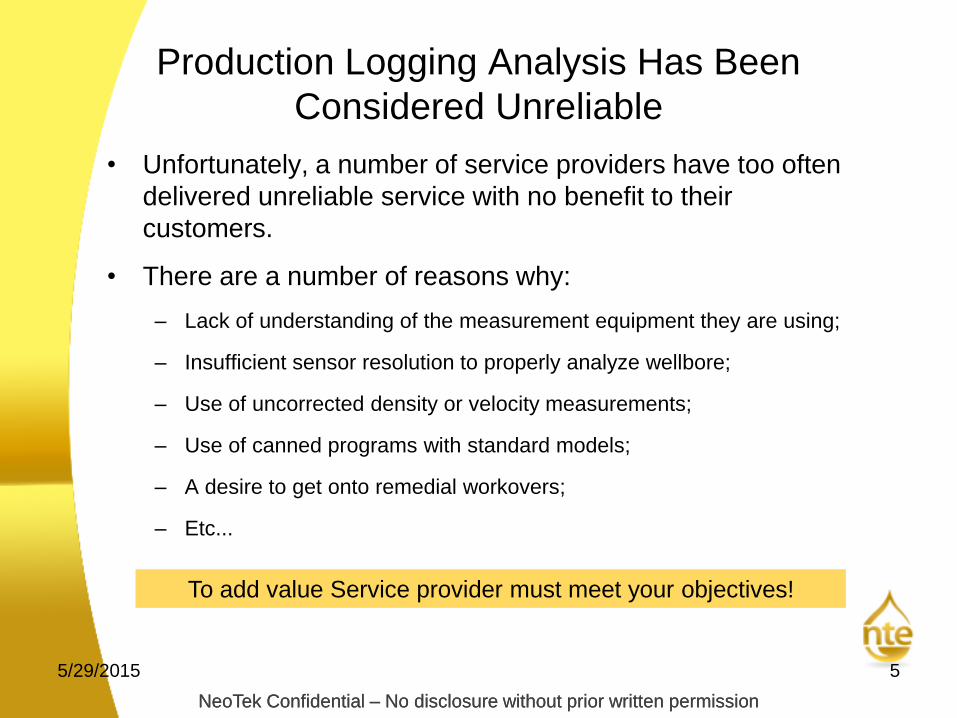
Production Logging Analysis Has Been
Considered Unreliable
• Unfortunately, a number of service providers have too often
delivered unreliable service with no benefit to their
customers.
• There are a number of reasons why:
– Lack of understanding of the measurement equipment they are using;
– Insufficient sensor resolution to properly analyze wellbore;
– Use of uncorrected density or velocity measurements;
– Use of canned programs with standard models;
– A desire to get onto remedial workovers;
– Etc...
5/29/2015 5
To add value Service provider must meet your objectives!

NeoTek Confidential – No disclosure without prior written permission5/29/2015
6
• Unfortunately, personnel are trained to input data and receive answers from canned programs. This is the extent of the analysis.
• A good analysis depends on two critical measurements:
• Velocity - from Spinner revolutions per second (RPS);
• Density – from differential pressure or radioactive density
• Both parameters are readily measured, but often misinterpreted.
Misinterpretation of Data is Prevalent in the
Industry

NeoTek Confidential – No disclosure without prior written permissionNeoTek Confidential – No disclosure without prior written permission
Example of Typical Mistakes - Velocity
5/29/2015 7
Fluid Spinner
Measurement
Correction
Factor .5
Average Fluid
Velocity is Estimated
and Annotated as
Vapp or APPARENT
velocity
This changes at each
entry or exit point
Fluid Spinner
Measurement
Average Fluid
Velocity
Correction Factor ? You Guess
Service provider must understand these limitations and factor
them into the analysis to eliminate errors

NeoTek Confidential – No disclosure without prior written permissionNeoTek Confidential – No disclosure without prior written permission
Example of Typical Mistakes - Density
5/29/2015 8
Sound knowledge of fluid flow dynamics increases the analysis
accuracy in wells below critical flow
Average Density =
Upward Flowing Fluid
+
Slippage Fluids

NeoTek Confidential – No disclosure without prior written permissionNeoTek Confidential – No disclosure without prior written permission
Consider Using Temperature to Confirm Our Analysis
5/29/2015 9
• Temperature is always faithful
• Accurately measured under all well conditions
• When fluid moves temperature moves with it
• Slope of temperature identifies changes in fluid movement
All analysis should be reconciled to temperature response
NeoTek Confidential – No disclosure without prior written permissionNeoTek Confidential – No disclosure without prior written permission
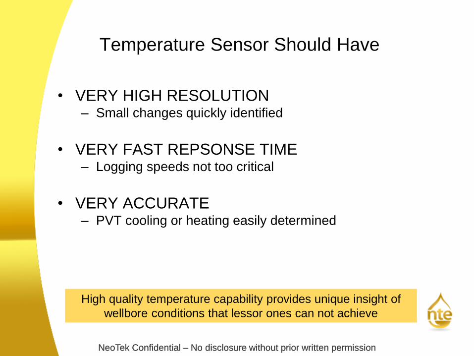
Temperature Sensor Should Have
• VERY HIGH RESOLUTION– Small changes quickly identified
• VERY FAST REPSONSE TIME– Logging speeds not too critical
• VERY ACCURATE– PVT cooling or heating easily determined
High quality temperature capability provides unique insight of
wellbore conditions that lessor ones can not achieve

NeoTek Confidential – No disclosure without prior written permissionNeoTek Confidential – No disclosure without prior written permission
Temperature Sensor Sensitive Enough to Identify
the Lithology in Thermally Stabilized Wells
5/29/2015 11
Joint Research between SMU
Geology and Mobil Research
With high resolution, fast response sensor correlation with the
gamma ray log possible – identifying the lithology

NeoTek Confidential – No disclosure without prior written permissionNeoTek Confidential – No disclosure without prior written permission
An Example of Using Temperature for a Complete
Analysis
5/29/2015 12
• A good clean example JT heating
and cooling and PVT cooling
• Water Source was determined in
this survey because the wellbore
was completed below perforations
far enough for logging tool to
measure.
NeoTek Confidential – No disclosure without prior written permissionNeoTek Confidential – No disclosure without prior written permission
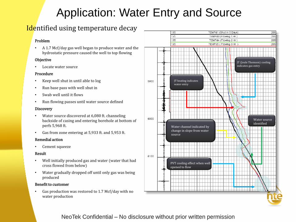
PVT cooling effect when wellopened to flow
Application: Water Entry and Source
JT (Joule Thomson) coolingindicates gas entry
JT heating indicates water entry
Water channel indicated bychange in slope from watersource
Water source identified
Problem
• A 1.7 Mcf/day gas well began to produce water and the hydrostatic pressure caused the well to top flowing
Objective
• Locate water source
Procedure
• Keep well shut in until able to log
• Run base pass with well shut in
• Swab well until it flows
• Run flowing passes until water source defined
Discovery
• Water source discovered at 6,080 ft. channeling backside of casing and entering borehole at bottom of perfs 5,968 ft.
• Gas from zone entering at 5,933 ft. and 5,953 ft.
Remedial action
• Cement squeeze
Result
• Well initially produced gas and water (water that had cross flowed from below)
• Water gradually dropped off until only gas was being produced
Benefit to customer
• Gas production was restored to 1.7 Mcf/day with no water production
Identified using temperature decay

NeoTek Confidential – No disclosure without prior written permission
Storage indicated from injectionprior to channel development
Water exiting borehole at top ofperforation indicated by spinner
Injection fluid channeling up behindcasing indicated by cooling from theinjected fluid
Discovery
• Spinner indicated injection water
leaving the borehole at top of
upper perforations
• Temperature indicates injected
fluid moving up behind casing to
zone at 1,530 ft.
Application: Injection ProfileProblem
• Injection pressure of the well suddenly dropped with no change in
injection rate
Objective
• Locate where injection fluid is leaving borehole and where it is stored
Procedure
• Make passes while injecting
fluid
• Shut injection off
• Make passes as
temperature decays back
toward gradient
Result
• Injected fluids revert back to intended
zones
Benefit to customer
• Water flood contributing to pressure zone
Remedial action
• Cement squeeze upper
perforations

NeoTek Confidential – No disclosure without prior written permission5/29/2015
15
Injection Well Channel Up

NeoTek Confidential – No disclosure without prior written permission5/29/2015
16
Injection Well Scaled

NeoTek Confidential – No disclosure without prior written permission
Application: After Frac & Cross Flow
Extent of frac is identified by RA tag seen on post-
frac GR and cool temperature signature where frac
fluids have been pumped to the formation
Cross flow between
perforated intervals
within frac zone
Communication behind pipe
during the frac treatment left a
temperature
signature
Objective
• Evaluate extent of frac treatment
Procedure
• Run base temperature log after cementing
• Frac was pumped approximately 1 month later
• Run shut-in temperature logs at intervals of 3 hours,
4 hours, 5 hours, and 6 hours after pumping frac
Discovery
• Identified the extent of frac treatment with both
Gamma Ray (GR) and temperature decay
• Cross flow within the frac zone and communication
above zone which could lead to channeling once the
zone depletes
Benefit to customer
• Better understanding of well performance will
improve decision making on future completions in the
field

NeoTek Confidential – No disclosure without prior written permissionNeoTek Confidential – No disclosure without prior written permission
It is Critical to Have a Thorough Understanding of
All Measurements to Provide an Accurate Analysis
• Your service provider should understand your objective and
have a game plan before they start
• They should have the expertise with their measurement systems
to eliminate common mistakes
• They need to reliably meet your objective to add value
Service provider must measures itself by your success!

NeoTek Confidential – No disclosure without prior written permissionNeoTek Confidential – No disclosure without prior written permission
Our Production Logging Tools Are Differentiated by Very High Temp
/ High Pressure Operation
5/29/2015 19
Gamma Ray
MP = 111”
Quartz Pressure
MP = 44”
Collar Locator
MP = 30”
Temperature
Capacitance
MP=18”
Spinner
MP=4”
Tool Zero
Gamma Ray Detector
Type: Scintillation
Pressure Sensor
Type: Quartz Crystal
Accuracy: ± 0.03% F.S.
Resolution: 0.01 psi
Ranges: 10k, 16k, 20k
Make: Quartzdyne
Collar Locator
Type: Coil / Rare Earth
Magnet
Temperature (Borehole)
Rating: 285/ 450 /650 F
Type: Platinum RTD
Accuracy: ± 1 Deg. C.
Resolution: 0.001 Deg. C.
Response: 0 - 100 Deg. C (4
seconds)
Temperature (Compensation)
Accuracy: ± 1 Deg. C.
Resolution: 0.01 Deg. C.
Capacitance (Fluid I.D.)
Determine water presence in well
bore fluids.
Flow Meter (Spinner)
Type: Continuous
Sensors: Reed Switch / Magnetic
Resolution: 0.25 rps or 0.08 rps
Data Status: Velocity / Direction /
Diagnostics
The Modular Design Makes Adding Our Chemical Sensing Capability a Straight-
Forward Development Project

NeoTek Confidential – No disclosure without prior written permission5/29/2015
20

NeoTek Confidential – No disclosure without prior written permission5/29/2015
21
Water Channeling From Above Zone