configuring service policy rules on firewall devices€¦ · 57-3 user guide for cisco security...
TRANSCRIPT
C H A P T E R 57
Configuring Service Policy Rules on Firewall DevicesThis section describes configuring service policy rules. Service policies provide a consistent and flexible way to configure certain security appliance features, including priority queuing, application inspection, and QoS (quality of service). For example, you can use a service policy to create a timeout configuration that is specific to a particular TCP application, as opposed to one that applies to all TCP applications.
Note Detailed information regarding the range and implementation of particular service policies can be found on cisco.com. For example, the following references may be helpful:
Using Modular Policy Framework
QoS Configuration and Monitoring
This chapter contains the following topics:
• About Service Policy Rules, page 57-1
• About TCP State Bypass, page 57-3
• Priority Queues Page, page 57-4
• Service Policy Rules Page, page 57-5
• Configuring Traffic Flow Objects, page 57-17
• Configuring TCP Maps, page 57-21
About Service Policy RulesService policy rules encompass these features:
• TCP and general connection settings (including TCP State Bypass; see About TCP State Bypass, page 57-3)
• Content security control (CSC)
• Application inspection
• Intrusion Prevention Services
• QoS queuing and policing
57-1User Guide for Cisco Security Manager 4.10
Chapter 57 Configuring Service Policy Rules on Firewall DevicesAbout Service Policy Rules
• ASA CX redirection (see About the ASA CX, page 57-16)
• ASA FirePOWER redirection
• User statistics for identity-based firewall policies
The configuration options for these features are presented on two pages in Security Manager—Priority Queues and Rules—accessed by navigating to Platform > Service Policy.
Priority Queuing
Priority queuing establishes two queues on an interface, a Low Latency Queuing (LLQ) priority queue and a “best effort” queue. This lets you prioritize latency-sensitive traffic like voice and video, so it is transmitted ahead of other traffic. Packets in the priority queue are always transmitted before packets in the best effort queue.
Because queues are not of infinite size, they can fill and overflow. When a queue is full, additional packets cannot get into the queue and are dropped. This is called “tail drop.” To minimize tail drop, you can increase the queue buffer size. You can also fine-tune the maximum number of packets allowed into the transmit queue. These options let you control the latency and robustness of priority queuing.
Priority queuing is a Quality of Service (QoS) feature. In Security Manager, priority queue size and transmit queue size are managed on the Priority Queues Page, page 57-4, while establishment of priority queuing for a traffic class is an option on the QoS tab of the Service Policy (MPC) Rule Wizard, which is accessed from the Service Policy Rules Page, page 57-5.
Application Inspection and QoS
Some applications require special handling by the security appliance, and specific application inspection engines are provided for this purpose. Specifically, applications that embed IP addressing information in the user data packet, or open secondary channels on dynamically assigned ports require special inspection.
Application inspection is enabled by default for many protocols, while it is disabled for others. In many cases, you can change the port which the application inspection engine monitors for traffic.
Application inspection engines work with network address translation (NAT) to help identify the location of embedded addressing information. This allows NAT to translate these embedded addresses, and to update any checksum or other fields that are affected by the translation.
Service policy rules define how specific types of application inspection are applied to different types of traffic processed by the security appliance. You can apply rules to specific interfaces, or globally to every interface.
These rules provide a means to configure security appliance features in a manner similar to the Cisco IOS software quality-of-service (QoS) CLI. For example, with service policy rules you can include IP Precedence as one of the criteria to identify traffic for rate-limiting. You can also create a timeout configuration that is specific to a particular TCP application, as opposed to one that applies to all TCP applications.
Traffic match criteria are used to define the types of traffic to which you want to apply application inspection. For example, TCP traffic on port 23 might be classified as the Telnet traffic class. You then might use the traffic class to apply connection limits.
Multiple traffic match criteria can be assigned to a single interface, but a packet will only match the first criteria within a specific service policy rule.
57-2User Guide for Cisco Security Manager 4.10
Chapter 57 Configuring Service Policy Rules on Firewall DevicesAbout TCP State Bypass
About TCP State BypassBy default, all traffic that enters an ASA or FWSM is inspected using the Adaptive Security Algorithm, and is either allowed through or dropped based on the security policy. The device maximizes its firewall performance by checking the state of each packet—to determine whether this a new connection, or an established connection—and assigning it to the session management path (if it is a new connection SYN packet), the fast path (if it is an established connection), or the control-plane path (for advanced inspection).
Note TCP State Bypass is available on FWSM 3.2+ and ASA 8.2+ devices only.
TCP packets that match existing connections in the fast path can pass through the appliance without every aspect of the security policy being rechecked. This feature maximizes performance. However, the method of establishing the session in the fast path using the SYN packet, and the checks that occur in the fast path (such as TCP sequence number), require that both outbound and inbound flows for a connection pass through the same device, which is not the case in asymmetric routing environments.
For example, assume a new connection is assigned to security device 1. The SYN packet goes through the session management path, and an entry for the connection is added to the fast path table. If subsequent packets of this connection go through device 1, then the packets match the entry in the fast path, and are passed through. But if subsequent packets go to device 2, where a SYN packet did not go through the session management path, there is no entry in the fast path for the connection, and the packets are dropped.
Thus, if you have asymmetric routing configured on upstream routers, and traffic alternates between two security devices, enable TCP state bypass for those specific traffic flows. TCP state bypass alters the way sessions are established in the fast path and disables the fast path checks. TCP traffic is then treated much as a UDP connection is treated: when a non-SYN packet matching the specified networks enters the security device, and there is not a fast path entry, then the packet goes through the session management path to establish a connection in the fast path. Once in the fast path, the traffic bypasses the fast path checks.
Unsupported Features
The following features are not supported when you enable TCP state bypass:
• Application inspection – Application inspection requires both inbound and outbound traffic to go through the same security device, so application inspection is not supported with TCP state bypass.
• AAA authenticated sessions – When a user authenticates with one security device, traffic returning via the other security device will be denied because the user did not authenticate with that device.
• TCP Intercept, Maximum Embryonic Connections limit, TCP sequence number randomization – If TCP state bypass is enabled, the device does not keep track of the state of the connection, so these features are not applicable.
• Cisco CSC SSM (Content Security and Control Security Services Module) – SSM and SSC functionality cannot be used with TCP state bypass.
Compatibility with NAT
Because the translation session is established separately for each security device, be sure to configure static NAT on both devices for TCP state bypass traffic; if you use dynamic NAT, the address chosen for the session on device 1 will differ from the address chosen for the session on device 2.
57-3User Guide for Cisco Security Manager 4.10
Chapter 57 Configuring Service Policy Rules on Firewall DevicesPriority Queues Page
Related Topics
• About Service Policy Rules, page 57-1
Priority Queues PagePriority queues let you define how traffic is prioritized in the network. You can define a series of filters based on packet characteristics to cause traffic to be placed in a higher or lower priority queue. The queue with the highest priority is serviced first until it is empty, then the lower queues are serviced in sequence.
In Security Manager, priority queue size and transmit queue size are managed on this page, while establishment of priority queuing for a traffic class is an option on the QoS tab of the Service Policy (MPC) Rule Wizard, which is accessed from the Service Policy Rules Page, page 57-5.
The Priority Queue Configuration dialog box is used to add and edit these queues. Refer to Priority Queue Configuration Dialog Box, page 57-4 for descriptions of the fields displayed in the Priority Queues table on this page.
Note Priority queuing is are not available on Catalyst 6500 service modules (the Firewall Services Module and the Adaptive Security Appliance Service Module).
Navigation Path
• (Device view) Select Platform > Service Policy > Priority Queues from the Device Policy selector.
• (Policy view) Select PIX/ASA/FWSM Platform > Service Policy > Priority Queues from the Policy Type selector. Select an existing policy from the Shared Policy selector, or create a new one.
Related Topics
• Chapter 57, “Configuring Service Policy Rules on Firewall Devices”
• Insert/Edit Service Policy (MPC) Rule Wizard, page 57-6
• About Service Policy Rules, page 57-1
• Understanding Queuing Parameters, page 65-4
Priority Queue Configuration Dialog BoxUse the Priority Queue Configuration dialog box to define and edit the priority queues on the Priority Queues page.
Note Priority queuing is are not available on Catalyst 6500 service modules (the Firewall Services Module and the Adaptive Security Appliance Service Module).
Navigation Path
You open the Priority Queue Configuration dialog box by clicking the Add Row or Edit Row buttons on the Priority Queues Page, page 57-4.
Related Topics
• Chapter 57, “Configuring Service Policy Rules on Firewall Devices”
57-4User Guide for Cisco Security Manager 4.10
Chapter 57 Configuring Service Policy Rules on Firewall DevicesService Policy Rules Page
• Insert/Edit Service Policy (MPC) Rule Wizard, page 57-6
• About Service Policy Rules, page 57-1
• Understanding Queuing Parameters, page 65-4
Field Reference
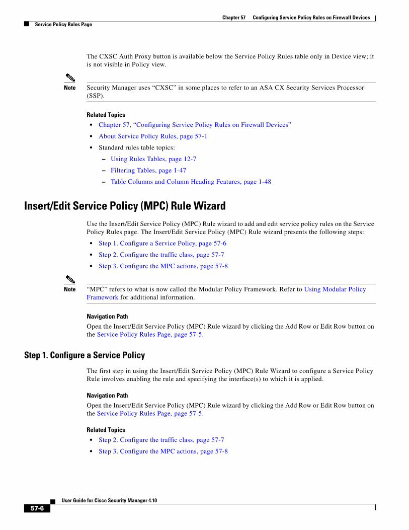
Service Policy Rules PageUse the Service Policy Rules page to define new service policy rules, and to edit or delete existing service policy rules.
Configuring Service Policy Rules consists of three tasks:
1. Configure a service policy. Create a service policy and determine the interfaces to which the service policy applies. For more information, see Step 1. Configure a Service Policy, page 57-6.
2. Configure the traffic class. Specify the criteria you want to use to identify the traffic to which the service policy applies. For more information, see Step 2. Configure the traffic class, page 57-7.
3. Configure the actions. Specify the actions that should be taken to protect information or resources, or to perform QoS functions for the traffic specified in this service policy. For more information, see Step 3. Configure the MPC actions, page 57-8.
The three tasks are performed using the Insert/Edit Service Policy (MPC) Rule Wizard, page 57-6. Refer to the individual task topics for descriptions of the fields displayed in the Service Policy Rules table on this page.
Navigation Path
• (Device view) Select Platform > Service Policy > Rules from the Device Policy selector.
• (Policy view) Select PIX/ASA/FWSM Platform > Service Policy > Rules from the Policy Type selector. Select an existing policy from the Shared Policy selector, or create a new one.
ASA CX Auth Proxy Configuration
The CXSC Auth Proxy button below the Service Policy Rules table opens the Add/Edit CXSC Auth Proxy Configuration dialog box, which is described in ASA CX Auth Proxy Configuration, page 57-16.
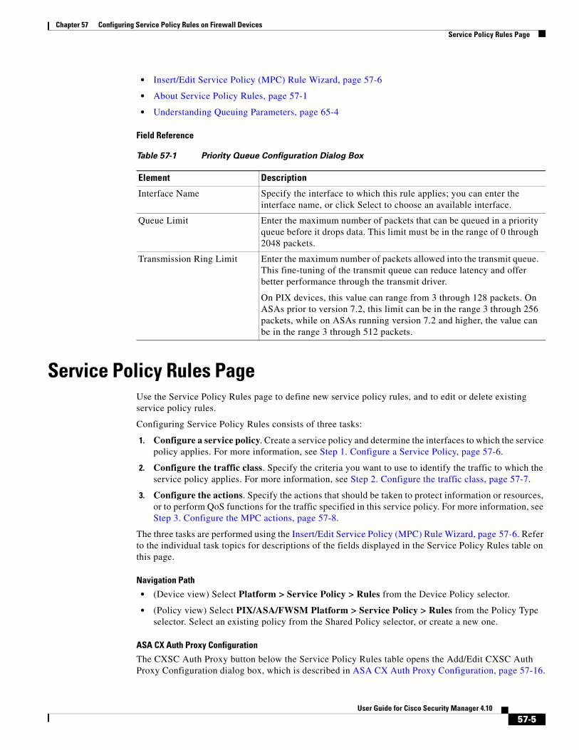
Table 57-1 Priority Queue Configuration Dialog Box
Element Description
Interface Name Specify the interface to which this rule applies; you can enter the interface name, or click Select to choose an available interface.
Queue Limit Enter the maximum number of packets that can be queued in a priority queue before it drops data. This limit must be in the range of 0 through 2048 packets.
Transmission Ring Limit Enter the maximum number of packets allowed into the transmit queue. This fine-tuning of the transmit queue can reduce latency and offer better performance through the transmit driver.
On PIX devices, this value can range from 3 through 128 packets. On ASAs prior to version 7.2, this limit can be in the range 3 through 256 packets, while on ASAs running version 7.2 and higher, the value can be in the range 3 through 512 packets.
57-5User Guide for Cisco Security Manager 4.10
Chapter 57 Configuring Service Policy Rules on Firewall DevicesService Policy Rules Page
The CXSC Auth Proxy button is available below the Service Policy Rules table only in Device view; it is not visible in Policy view.
Note Security Manager uses “CXSC” in some places to refer to an ASA CX Security Services Processor (SSP).
Related Topics
• Chapter 57, “Configuring Service Policy Rules on Firewall Devices”
• About Service Policy Rules, page 57-1
• Standard rules table topics:
– Using Rules Tables, page 12-7
– Filtering Tables, page 1-47
– Table Columns and Column Heading Features, page 1-48
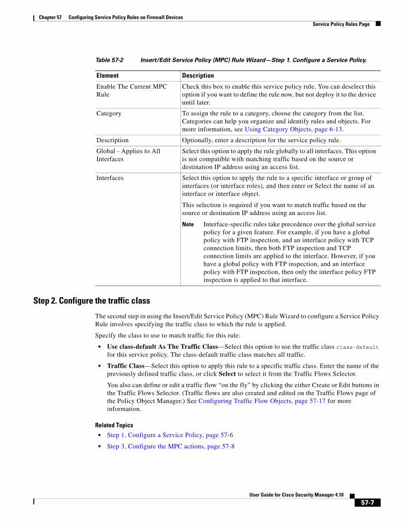
Insert/Edit Service Policy (MPC) Rule WizardUse the Insert/Edit Service Policy (MPC) Rule wizard to add and edit service policy rules on the Service Policy Rules page. The Insert/Edit Service Policy (MPC) Rule wizard presents the following steps:
• Step 1. Configure a Service Policy, page 57-6
• Step 2. Configure the traffic class, page 57-7
• Step 3. Configure the MPC actions, page 57-8
Note “MPC” refers to what is now called the Modular Policy Framework. Refer to Using Modular Policy Framework for additional information.
Navigation Path
Open the Insert/Edit Service Policy (MPC) Rule wizard by clicking the Add Row or Edit Row button on the Service Policy Rules Page, page 57-5.
Step 1. Configure a Service Policy
The first step in using the Insert/Edit Service Policy (MPC) Rule Wizard to configure a Service Policy Rule involves enabling the rule and specifying the interface(s) to which it is applied.
Navigation Path
Open the Insert/Edit Service Policy (MPC) Rule wizard by clicking the Add Row or Edit Row button on the Service Policy Rules Page, page 57-5.
Related Topics
• Step 2. Configure the traffic class, page 57-7
• Step 3. Configure the MPC actions, page 57-8
57-6User Guide for Cisco Security Manager 4.10
Chapter 57 Configuring Service Policy Rules on Firewall DevicesService Policy Rules Page
Step 2. Configure the traffic class
The second step in using the Insert/Edit Service Policy (MPC) Rule Wizard to configure a Service Policy Rule involves specifying the traffic class to which the rule is applied.
Specify the class to use to match traffic for this rule:
• Use class-default As The Traffic Class—Select this option to use the traffic class class-default for this service policy. The class-default traffic class matches all traffic.
• Traffic Class—Select this option to apply this rule to a specific traffic class. Enter the name of the previously defined traffic class, or click Select to select it from the Traffic Flows Selector.
You also can define or edit a traffic flow “on the fly” by clicking the either Create or Edit buttons in the Traffic Flows Selector. (Traffic flows are also created and edited on the Traffic Flows page of the Policy Object Manager.) See Configuring Traffic Flow Objects, page 57-17 for more information.
Related Topics
• Step 1. Configure a Service Policy, page 57-6
• Step 3. Configure the MPC actions, page 57-8
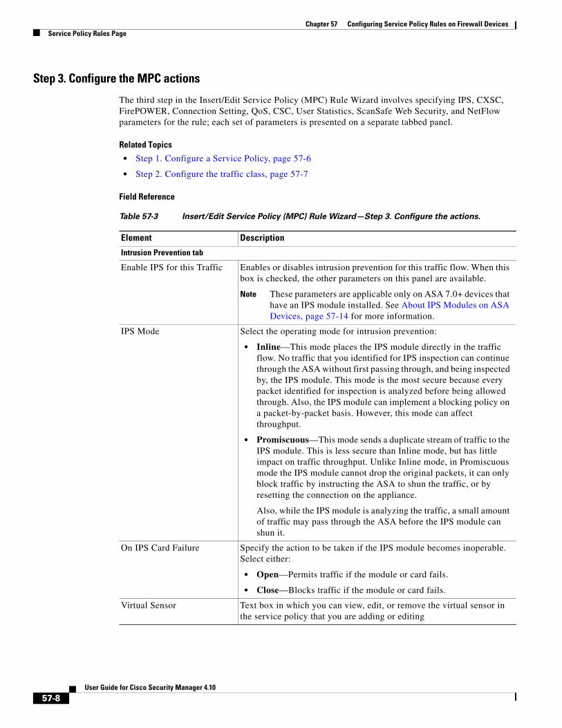
Table 57-2 Insert/Edit Service Policy (MPC) Rule Wizard—Step 1. Configure a Service Policy.
Element Description
Enable The Current MPC Rule
Check this box to enable this service policy rule. You can deselect this option if you want to define the rule now, but not deploy it to the device until later.
Category To assign the rule to a category, choose the category from the list. Categories can help you organize and identify rules and objects. For more information, see Using Category Objects, page 6-13.
Description Optionally, enter a description for the service policy rule.
Global - Applies to All Interfaces
Select this option to apply the rule globally to all interfaces. This option is not compatible with matching traffic based on the source or destination IP address using an access list.
Interfaces Select this option to apply the rule to a specific interface or group of interfaces (or interface roles), and then enter or Select the name of an interface or interface object.
This selection is required if you want to match traffic based on the source or destination IP address using an access list.
Note Interface-specific rules take precedence over the global service policy for a given feature. For example, if you have a global policy with FTP inspection, and an interface policy with TCP connection limits, then both FTP inspection and TCP connection limits are applied to the interface. However, if you have a global policy with FTP inspection, and an interface policy with FTP inspection, then only the interface policy FTP inspection is applied to that interface.
57-7User Guide for Cisco Security Manager 4.10
Chapter 57 Configuring Service Policy Rules on Firewall DevicesService Policy Rules Page
Step 3. Configure the MPC actions
The third step in the Insert/Edit Service Policy (MPC) Rule Wizard involves specifying IPS, CXSC, FirePOWER, Connection Setting, QoS, CSC, User Statistics, ScanSafe Web Security, and NetFlow parameters for the rule; each set of parameters is presented on a separate tabbed panel.
Related Topics
• Step 1. Configure a Service Policy, page 57-6
• Step 2. Configure the traffic class, page 57-7
Field Reference
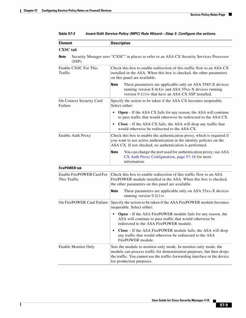
Table 57-3 Insert/Edit Service Policy (MPC) Rule Wizard—Step 3. Configure the actions.
Element Description
Intrusion Prevention tab
Enable IPS for this Traffic Enables or disables intrusion prevention for this traffic flow. When this box is checked, the other parameters on this panel are available.
Note These parameters are applicable only on ASA 7.0+ devices that have an IPS module installed. See About IPS Modules on ASA Devices, page 57-14 for more information.
IPS Mode Select the operating mode for intrusion prevention:
• Inline—This mode places the IPS module directly in the traffic flow. No traffic that you identified for IPS inspection can continue through the ASA without first passing through, and being inspected by, the IPS module. This mode is the most secure because every packet identified for inspection is analyzed before being allowed through. Also, the IPS module can implement a blocking policy on a packet-by-packet basis. However, this mode can affect throughput.
• Promiscuous—This mode sends a duplicate stream of traffic to the IPS module. This is less secure than Inline mode, but has little impact on traffic throughput. Unlike Inline mode, in Promiscuous mode the IPS module cannot drop the original packets, it can only block traffic by instructing the ASA to shun the traffic, or by resetting the connection on the appliance.
Also, while the IPS module is analyzing the traffic, a small amount of traffic may pass through the ASA before the IPS module can shun it.
On IPS Card Failure Specify the action to be taken if the IPS module becomes inoperable. Select either:
• Open—Permits traffic if the module or card fails.
• Close—Blocks traffic if the module or card fails.
Virtual Sensor Text box in which you can view, edit, or remove the virtual sensor in the service policy that you are adding or editing
57-8User Guide for Cisco Security Manager 4.10
Chapter 57 Configuring Service Policy Rules on Firewall DevicesService Policy Rules Page
CXSC tab
Note Security Manager uses “CXSC” in places to refer to an ASA CX Security Services Processor (SSP).
Enable CXSC For This Traffic
Check this box to enable redirection of this traffic flow to an ASA CX installed in the ASA. When this box is checked, the other parameters on this panel are available.
Note These parameters are applicable only on ASA 5585-X devices running version 8.4(4)+ and ASA 55xx-X devices running version 9.1(1)+ that have an ASA CX SSP installed.
On Context Security Card Failure
Specify the action to be taken if the ASA CX becomes inoperable. Select either:
• Open – If the ASA CX fails for any reason, the ASA will continue to pass traffic that would otherwise be redirected to the ASA CX.
• Close – If the ASA CX fails, the ASA will drop any traffic that would otherwise be redirected to the ASA CX.
Enable Auth Proxy Check this box to enable the authentication proxy, which is required if you want to use active authentication in the identity policies on the ASA CX. If not checked, no authentication is performed.
Note You can change the port used for authentication proxy; see ASA CX Auth Proxy Configuration, page 57-16 for more information.
FirePOWER tab
Enable FirePOWER Card For This Traffic
Check this box to enable redirection of this traffic flow to an ASA FirePOWER module installed in the ASA. When this box is checked, the other parameters on this panel are available.
Note These parameters are applicable only on ASA 55xx-X devices running version 9.2(1)+.
On FirePOWER Card Failure Specify the action to be taken if the ASA FirePOWER module becomes inoperable. Select either:
• Open – If the ASA FirePOWER module fails for any reason, the ASA will continue to pass traffic that would otherwise be redirected to the ASA FirePOWER module.
• Close – If the ASA FirePOWER module fails, the ASA will drop any traffic that would otherwise be redirected to the ASA FirePOWER module.
Enable Monitor Only Sets the module to monitor-only mode. In monitor-only mode, the module can process traffic for demonstration purposes, but then drops the traffic. You cannot use the traffic-forwarding interface or the device for production purposes.
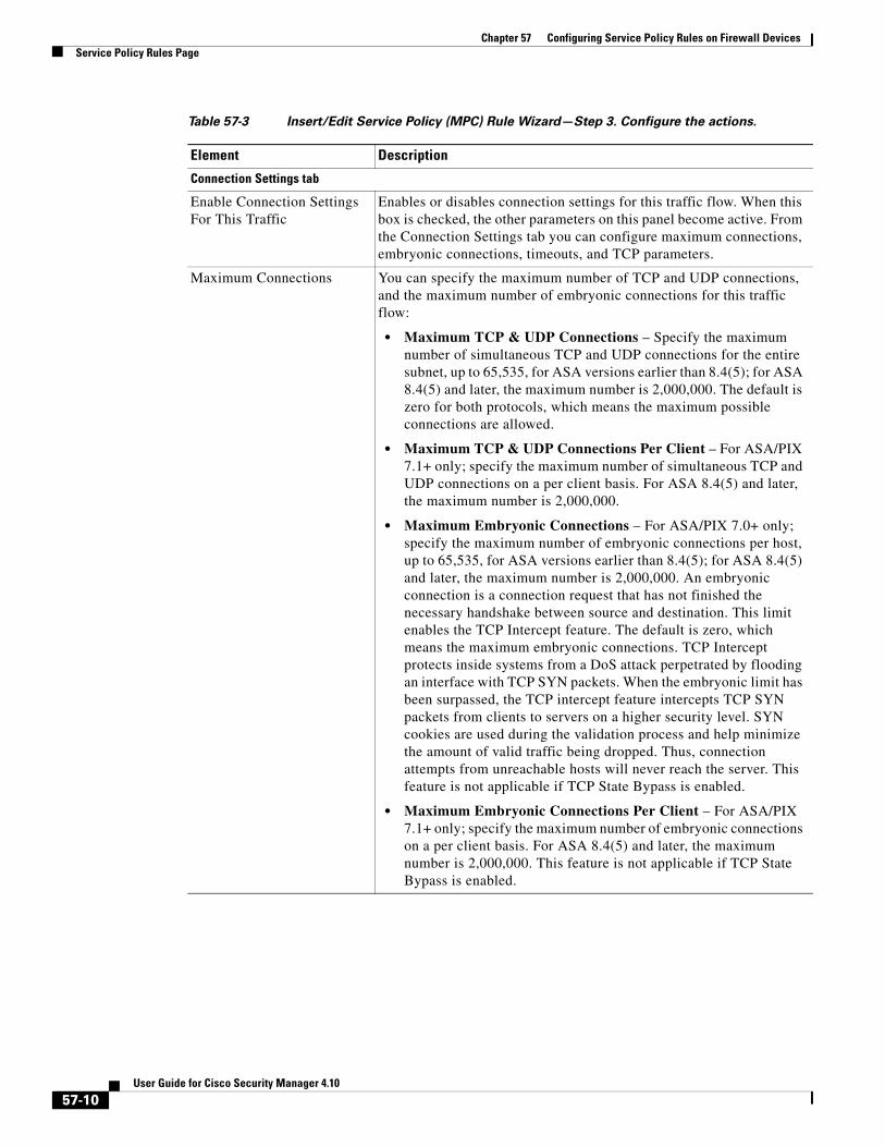
Table 57-3 Insert/Edit Service Policy (MPC) Rule Wizard—Step 3. Configure the actions.
Element Description
57-9User Guide for Cisco Security Manager 4.10
Chapter 57 Configuring Service Policy Rules on Firewall DevicesService Policy Rules Page
Connection Settings tab
Enable Connection Settings For This Traffic
Enables or disables connection settings for this traffic flow. When this box is checked, the other parameters on this panel become active. From the Connection Settings tab you can configure maximum connections, embryonic connections, timeouts, and TCP parameters.
Maximum Connections You can specify the maximum number of TCP and UDP connections, and the maximum number of embryonic connections for this traffic flow:
• Maximum TCP & UDP Connections – Specify the maximum number of simultaneous TCP and UDP connections for the entire subnet, up to 65,535, for ASA versions earlier than 8.4(5); for ASA 8.4(5) and later, the maximum number is 2,000,000. The default is zero for both protocols, which means the maximum possible connections are allowed.
• Maximum TCP & UDP Connections Per Client – For ASA/PIX 7.1+ only; specify the maximum number of simultaneous TCP and UDP connections on a per client basis. For ASA 8.4(5) and later, the maximum number is 2,000,000.
• Maximum Embryonic Connections – For ASA/PIX 7.0+ only; specify the maximum number of embryonic connections per host, up to 65,535, for ASA versions earlier than 8.4(5); for ASA 8.4(5) and later, the maximum number is 2,000,000. An embryonic connection is a connection request that has not finished the necessary handshake between source and destination. This limit enables the TCP Intercept feature. The default is zero, which means the maximum embryonic connections. TCP Intercept protects inside systems from a DoS attack perpetrated by flooding an interface with TCP SYN packets. When the embryonic limit has been surpassed, the TCP intercept feature intercepts TCP SYN packets from clients to servers on a higher security level. SYN cookies are used during the validation process and help minimize the amount of valid traffic being dropped. Thus, connection attempts from unreachable hosts will never reach the server. This feature is not applicable if TCP State Bypass is enabled.
• Maximum Embryonic Connections Per Client – For ASA/PIX 7.1+ only; specify the maximum number of embryonic connections on a per client basis. For ASA 8.4(5) and later, the maximum number is 2,000,000. This feature is not applicable if TCP State Bypass is enabled.
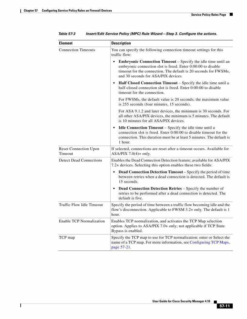
Table 57-3 Insert/Edit Service Policy (MPC) Rule Wizard—Step 3. Configure the actions.
Element Description
57-10User Guide for Cisco Security Manager 4.10
Chapter 57 Configuring Service Policy Rules on Firewall DevicesService Policy Rules Page
Connection Timeouts You can specify the following connection timeout settings for this traffic flow:
• Embryonic Connection Timeout – Specify the idle time until an embryonic connection slot is freed. Enter 0:00:00 to disable timeout for the connection. The default is 20 seconds for FWSMs, and 30 seconds for ASA/PIX devices.
• Half Closed Connection Timeout – Specify the idle time until a half-closed connection slot is freed. Enter 0:00:00 to disable timeout for the connection.
For FWSMs, the default value is 20 seconds; the maximum value is 255 seconds (four minutes, 15 seconds).
For ASA 9.1.2 and later devices, the minimum is 30 seconds. For all other ASA/PIX devices, the minimum is 5 minutes. The default is 10 minutes for all ASA/PIX devices.
• Idle Connection Timeout – Specify the idle time until a connection slot is freed. Enter 0:00:00 to disable timeout for the connection. This duration must be at least 5 minutes. The default is 1 hour.
Reset Connection Upon Timeout
If selected, connections are reset after a timeout occurs. Available for ASA/PIX 7.0(4)+ only.
Detect Dead Connections Enables the Dead Connection Detection feature; available for ASA/PIX 7.2+ devices. Selecting this option enables these two fields:
• Dead Connection Detection Timeout – Specify the period of time between retries when a dead connection is detected. The default is 15 seconds.
• Dead Connection Detection Retries – Specify the number of retries to be performed after a dead connection is detected. The default is five.
Traffic Flow Idle Timeout Specify the period of time between a traffic flow becoming idle and the flow’s disconnection. Applicable to FWSM 3.2+ only. The default is 1 hour.
Enable TCP Normalization Enables TCP normalization, and activates the TCP Map selection option. Applies to ASA/PIX 7.0+ only; not applicable if TCP State Bypass is enabled.
TCP map Specify the TCP map to use for TCP normalization: enter or Select the name of a TCP map. For more information, see Configuring TCP Maps, page 57-21.
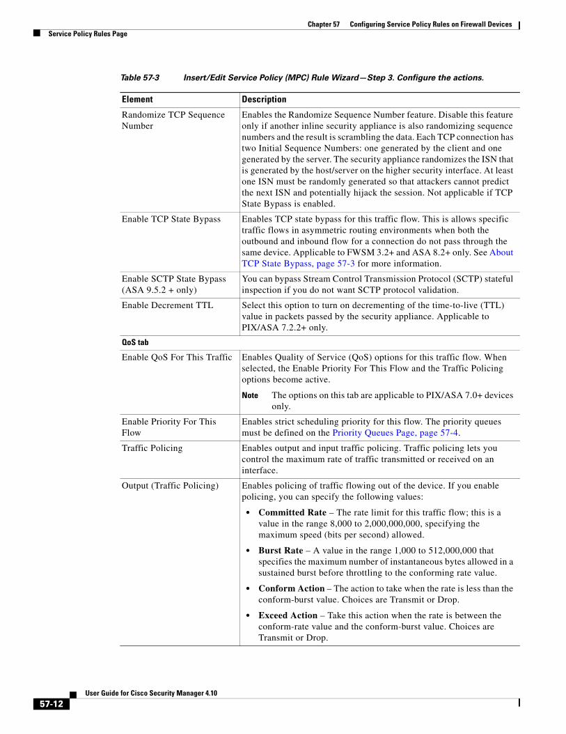
Table 57-3 Insert/Edit Service Policy (MPC) Rule Wizard—Step 3. Configure the actions.
Element Description
57-11User Guide for Cisco Security Manager 4.10
Chapter 57 Configuring Service Policy Rules on Firewall DevicesService Policy Rules Page
Randomize TCP Sequence Number
Enables the Randomize Sequence Number feature. Disable this feature only if another inline security appliance is also randomizing sequence numbers and the result is scrambling the data. Each TCP connection has two Initial Sequence Numbers: one generated by the client and one generated by the server. The security appliance randomizes the ISN that is generated by the host/server on the higher security interface. At least one ISN must be randomly generated so that attackers cannot predict the next ISN and potentially hijack the session. Not applicable if TCP State Bypass is enabled.
Enable TCP State Bypass Enables TCP state bypass for this traffic flow. This is allows specific traffic flows in asymmetric routing environments when both the outbound and inbound flow for a connection do not pass through the same device. Applicable to FWSM 3.2+ and ASA 8.2+ only. See About TCP State Bypass, page 57-3 for more information.
Enable SCTP State Bypass (ASA 9.5.2 + only)
You can bypass Stream Control Transmission Protocol (SCTP) stateful inspection if you do not want SCTP protocol validation.
Enable Decrement TTL Select this option to turn on decrementing of the time-to-live (TTL) value in packets passed by the security appliance. Applicable to PIX/ASA 7.2.2+ only.
QoS tab
Enable QoS For This Traffic Enables Quality of Service (QoS) options for this traffic flow. When selected, the Enable Priority For This Flow and the Traffic Policing options become active.
Note The options on this tab are applicable to PIX/ASA 7.0+ devices only.
Enable Priority For This Flow
Enables strict scheduling priority for this flow. The priority queues must be defined on the Priority Queues Page, page 57-4.
Traffic Policing Enables output and input traffic policing. Traffic policing lets you control the maximum rate of traffic transmitted or received on an interface.
Output (Traffic Policing) Enables policing of traffic flowing out of the device. If you enable policing, you can specify the following values:
• Committed Rate – The rate limit for this traffic flow; this is a value in the range 8,000 to 2,000,000,000, specifying the maximum speed (bits per second) allowed.
• Burst Rate – A value in the range 1,000 to 512,000,000 that specifies the maximum number of instantaneous bytes allowed in a sustained burst before throttling to the conforming rate value.
• Conform Action – The action to take when the rate is less than the conform-burst value. Choices are Transmit or Drop.
• Exceed Action – Take this action when the rate is between the conform-rate value and the conform-burst value. Choices are Transmit or Drop.
Table 57-3 Insert/Edit Service Policy (MPC) Rule Wizard—Step 3. Configure the actions.
Element Description
57-12User Guide for Cisco Security Manager 4.10
Chapter 57 Configuring Service Policy Rules on Firewall DevicesService Policy Rules Page
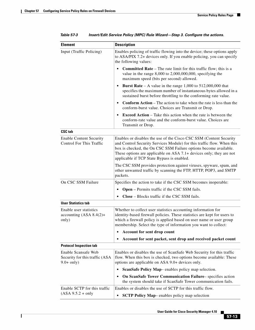
Input (Traffic Policing) Enables policing of traffic flowing into the device; these options apply to ASA/PIX 7.2+ devices only. If you enable policing, you can specify the following values:
• Committed Rate – The rate limit for this traffic flow; this is a value in the range 8,000 to 2,000,000,000, specifying the maximum speed (bits per second) allowed.
• Burst Rate – A value in the range 1,000 to 512,000,000 that specifies the maximum number of instantaneous bytes allowed in a sustained burst before throttling to the conforming rate value.
• Conform Action – The action to take when the rate is less than the conform-burst value. Choices are Transmit or Drop.
• Exceed Action – Take this action when the rate is between the conform-rate value and the conform-burst value. Choices are Transmit or Drop.
CSC tab
Enable Content Security Control For This Traffic
Enables or disables the use of the Cisco CSC SSM (Content Security and Control Security Services Module) for this traffic flow. When this box is checked, the On CSC SSM Failure options become available. These options are applicable on ASA 7.1+ devices only; they are not applicable if TCP State Bypass is enabled.
The CSC SSM provides protection against viruses, spyware, spam, and other unwanted traffic by scanning the FTP, HTTP, POP3, and SMTP packets.
On CSC SSM Failure Specifies the action to take if the CSC SSM becomes inoperable:
• Open – Permits traffic if the CSC SSM fails.
• Close – Blocks traffic if the CSC SSM fails.
User Statistics tab
Enable user statistics accounting (ASA 8.4(2)+ only)
Whether to collect user statistics accounting information for identity-based firewall policies. These statistics are kept for users to which a firewall policy is applied based on user name or user group membership. Select the type of information you want to collect:
• Account for sent drop count
• Account for sent packet, sent drop and received packet count
Protocol Inspection tab
Enable Scansafe Web Security for this traffic (ASA 9.0+ only)
Enables or disables the use of ScanSafe Web Security for this traffic flow. When this box is checked, two options become available: These options are applicable on ASA 9.0+ devices only.
• ScanSafe Policy Map– enables policy map selection.
• On ScanSafe Tower Communication Failure– specifies action the system should take if ScanSafe Tower communication fails.
Enable SCTP for this traffic (ASA 9.5.2 + only
Enables or disables the use of SCTP for this traffic flow.
• SCTP Policy Map– enables policy map selection
Table 57-3 Insert/Edit Service Policy (MPC) Rule Wizard—Step 3. Configure the actions.
Element Description
57-13User Guide for Cisco Security Manager 4.10
Chapter 57 Configuring Service Policy Rules on Firewall DevicesService Policy Rules Page
About IPS Modules on ASA Devices
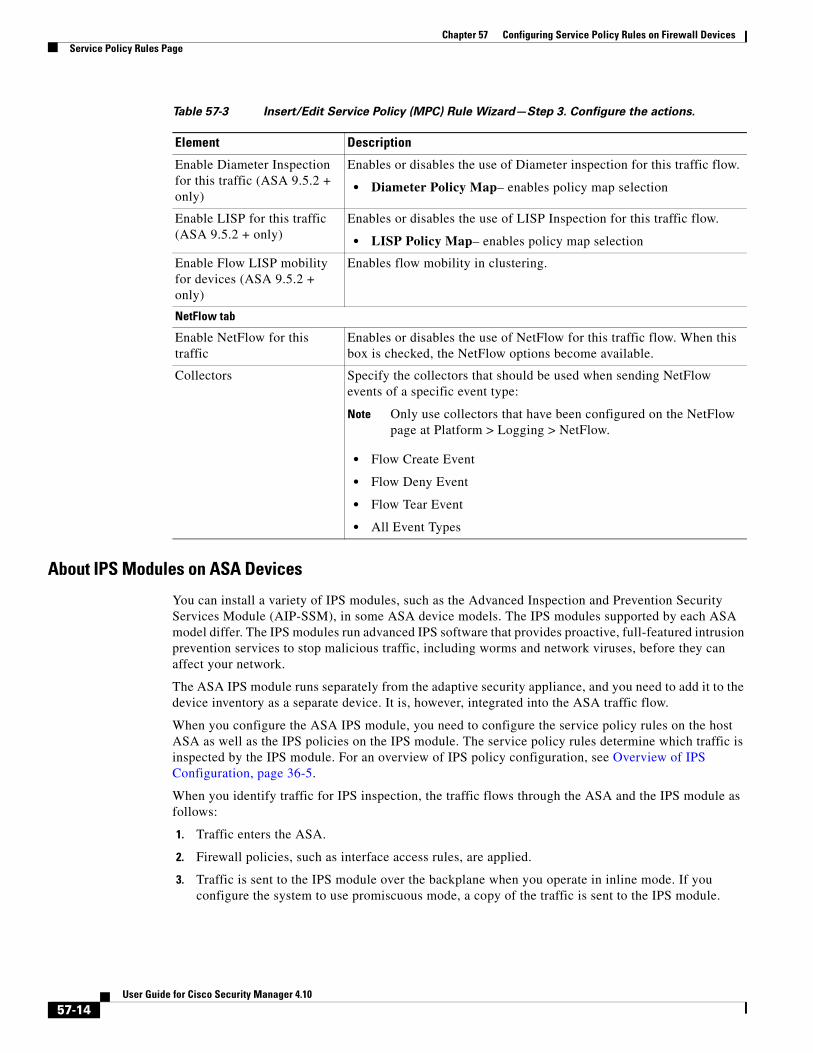
You can install a variety of IPS modules, such as the Advanced Inspection and Prevention Security Services Module (AIP-SSM), in some ASA device models. The IPS modules supported by each ASA model differ. The IPS modules run advanced IPS software that provides proactive, full-featured intrusion prevention services to stop malicious traffic, including worms and network viruses, before they can affect your network.
The ASA IPS module runs separately from the adaptive security appliance, and you need to add it to the device inventory as a separate device. It is, however, integrated into the ASA traffic flow.
When you configure the ASA IPS module, you need to configure the service policy rules on the host ASA as well as the IPS policies on the IPS module. The service policy rules determine which traffic is inspected by the IPS module. For an overview of IPS policy configuration, see Overview of IPS Configuration, page 36-5.
When you identify traffic for IPS inspection, the traffic flows through the ASA and the IPS module as follows:
1. Traffic enters the ASA.
2. Firewall policies, such as interface access rules, are applied.
3. Traffic is sent to the IPS module over the backplane when you operate in inline mode. If you configure the system to use promiscuous mode, a copy of the traffic is sent to the IPS module.
Enable Diameter Inspection for this traffic (ASA 9.5.2 + only)
Enables or disables the use of Diameter inspection for this traffic flow.
• Diameter Policy Map– enables policy map selection
Enable LISP for this traffic (ASA 9.5.2 + only)
Enables or disables the use of LISP Inspection for this traffic flow.
• LISP Policy Map– enables policy map selection
Enable Flow LISP mobility for devices (ASA 9.5.2 + only)
Enables flow mobility in clustering.
NetFlow tab
Enable NetFlow for this traffic
Enables or disables the use of NetFlow for this traffic flow. When this box is checked, the NetFlow options become available.
Collectors Specify the collectors that should be used when sending NetFlow events of a specific event type:
Note Only use collectors that have been configured on the NetFlow page at Platform > Logging > NetFlow.
• Flow Create Event
• Flow Deny Event
• Flow Tear Event
• All Event Types
Table 57-3 Insert/Edit Service Policy (MPC) Rule Wizard—Step 3. Configure the actions.
Element Description
57-14User Guide for Cisco Security Manager 4.10
Chapter 57 Configuring Service Policy Rules on Firewall DevicesService Policy Rules Page
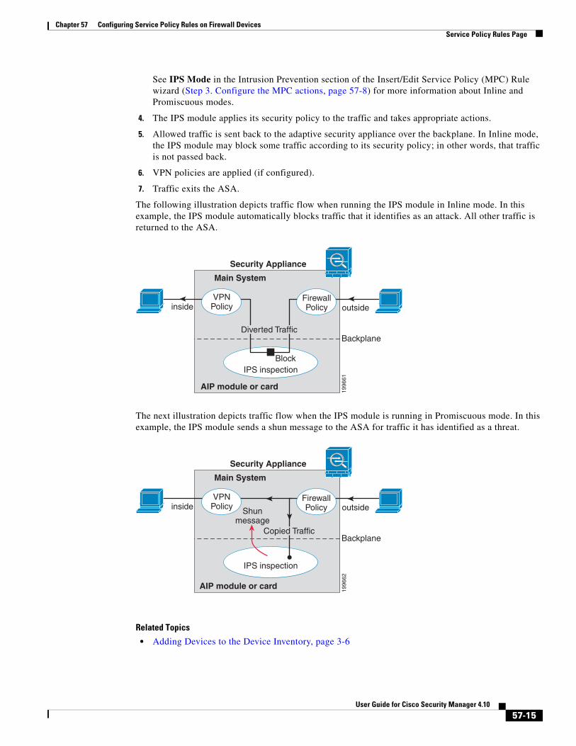
See IPS Mode in the Intrusion Prevention section of the Insert/Edit Service Policy (MPC) Rule wizard (Step 3. Configure the MPC actions, page 57-8) for more information about Inline and Promiscuous modes.
4. The IPS module applies its security policy to the traffic and takes appropriate actions.
5. Allowed traffic is sent back to the adaptive security appliance over the backplane. In Inline mode, the IPS module may block some traffic according to its security policy; in other words, that traffic is not passed back.
6. VPN policies are applied (if configured).
7. Traffic exits the ASA.
The following illustration depicts traffic flow when running the IPS module in Inline mode. In this example, the IPS module automatically blocks traffic that it identifies as an attack. All other traffic is returned to the ASA.
The next illustration depicts traffic flow when the IPS module is running in Promiscuous mode. In this example, the IPS module sends a shun message to the ASA for traffic it has identified as a threat.
Related Topics
• Adding Devices to the Device Inventory, page 3-6
Security Appliance
Main System
inside
AIP module or card
Diverted Traffic
IPS inspection
outside
Backplane
VPNPolicy
FirewallPolicy
Block
1996
61
Security Appliance
Main System
inside
AIP module or card
IPS inspection
outside
Backplane
VPNPolicy
Firewall Policy Shun
message
1996
62
Copied Traffic
57-15User Guide for Cisco Security Manager 4.10
Chapter 57 Configuring Service Policy Rules on Firewall DevicesService Policy Rules Page
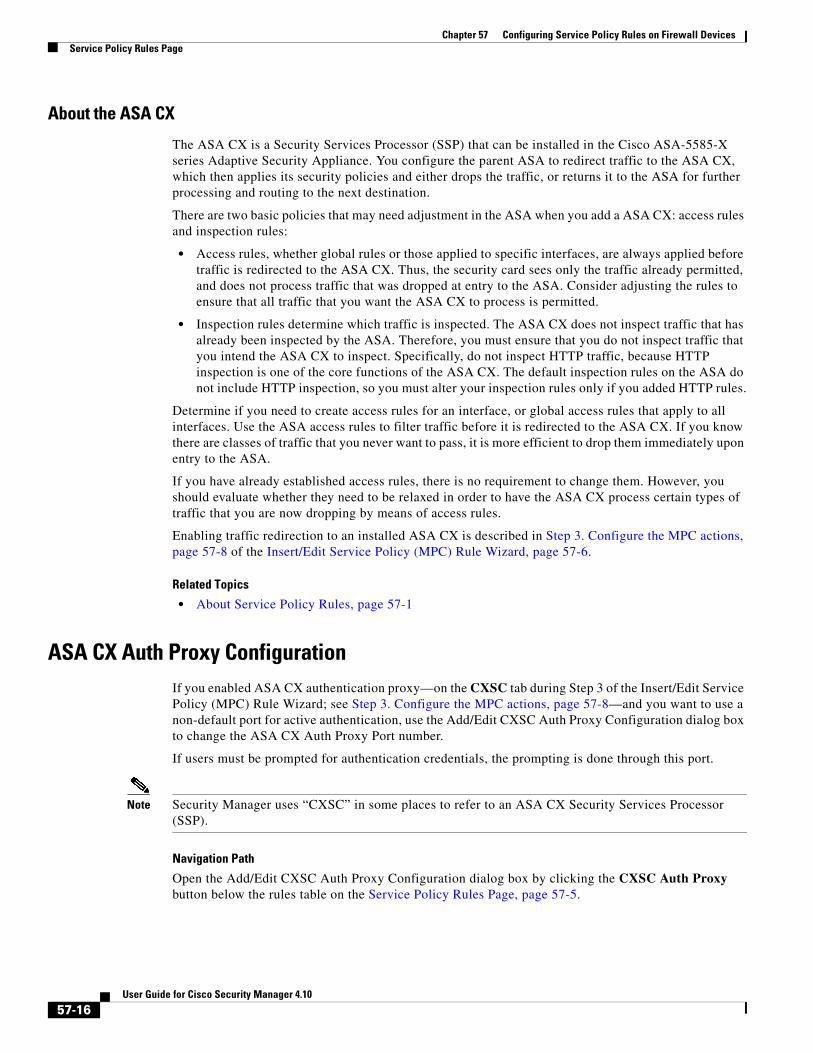
About the ASA CX
The ASA CX is a Security Services Processor (SSP) that can be installed in the Cisco ASA-5585-X series Adaptive Security Appliance. You configure the parent ASA to redirect traffic to the ASA CX, which then applies its security policies and either drops the traffic, or returns it to the ASA for further processing and routing to the next destination.
There are two basic policies that may need adjustment in the ASA when you add a ASA CX: access rules and inspection rules:
• Access rules, whether global rules or those applied to specific interfaces, are always applied before traffic is redirected to the ASA CX. Thus, the security card sees only the traffic already permitted, and does not process traffic that was dropped at entry to the ASA. Consider adjusting the rules to ensure that all traffic that you want the ASA CX to process is permitted.
• Inspection rules determine which traffic is inspected. The ASA CX does not inspect traffic that has already been inspected by the ASA. Therefore, you must ensure that you do not inspect traffic that you intend the ASA CX to inspect. Specifically, do not inspect HTTP traffic, because HTTP inspection is one of the core functions of the ASA CX. The default inspection rules on the ASA do not include HTTP inspection, so you must alter your inspection rules only if you added HTTP rules.
Determine if you need to create access rules for an interface, or global access rules that apply to all interfaces. Use the ASA access rules to filter traffic before it is redirected to the ASA CX. If you know there are classes of traffic that you never want to pass, it is more efficient to drop them immediately upon entry to the ASA.
If you have already established access rules, there is no requirement to change them. However, you should evaluate whether they need to be relaxed in order to have the ASA CX process certain types of traffic that you are now dropping by means of access rules.
Enabling traffic redirection to an installed ASA CX is described in Step 3. Configure the MPC actions, page 57-8 of the Insert/Edit Service Policy (MPC) Rule Wizard, page 57-6.
Related Topics
• About Service Policy Rules, page 57-1
ASA CX Auth Proxy Configuration If you enabled ASA CX authentication proxy—on the CXSC tab during Step 3 of the Insert/Edit Service Policy (MPC) Rule Wizard; see Step 3. Configure the MPC actions, page 57-8—and you want to use a non-default port for active authentication, use the Add/Edit CXSC Auth Proxy Configuration dialog box to change the ASA CX Auth Proxy Port number.
If users must be prompted for authentication credentials, the prompting is done through this port.
Note Security Manager uses “CXSC” in some places to refer to an ASA CX Security Services Processor (SSP).
Navigation Path
Open the Add/Edit CXSC Auth Proxy Configuration dialog box by clicking the CXSC Auth Proxy button below the rules table on the Service Policy Rules Page, page 57-5.
57-16User Guide for Cisco Security Manager 4.10
Chapter 57 Configuring Service Policy Rules on Firewall DevicesConfiguring Traffic Flow Objects
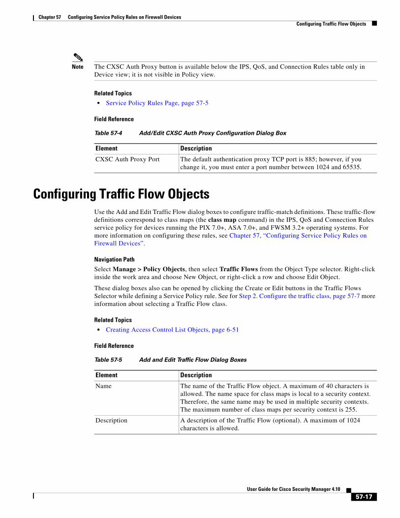
Note The CXSC Auth Proxy button is available below the IPS, QoS, and Connection Rules table only in Device view; it is not visible in Policy view.
Related Topics
• Service Policy Rules Page, page 57-5
Field Reference
Configuring Traffic Flow ObjectsUse the Add and Edit Traffic Flow dialog boxes to configure traffic-match definitions. These traffic-flow definitions correspond to class maps (the class map command) in the IPS, QoS and Connection Rules service policy for devices running the PIX 7.0+, ASA 7.0+, and FWSM 3.2+ operating systems. For more information on configuring these rules, see Chapter 57, “Configuring Service Policy Rules on Firewall Devices”.
Navigation Path
Select Manage > Policy Objects, then select Traffic Flows from the Object Type selector. Right-click inside the work area and choose New Object, or right-click a row and choose Edit Object.
These dialog boxes also can be opened by clicking the Create or Edit buttons in the Traffic Flows Selector while defining a Service Policy rule. See for Step 2. Configure the traffic class, page 57-7 more information about selecting a Traffic Flow class.
Related Topics
• Creating Access Control List Objects, page 6-51
Field Reference
Table 57-4 Add/Edit CXSC Auth Proxy Configuration Dialog Box
Element Description
CXSC Auth Proxy Port The default authentication proxy TCP port is 885; however, if you change it, you must enter a port number between 1024 and 65535.
Table 57-5 Add and Edit Traffic Flow Dialog Boxes
Element Description
Name The name of the Traffic Flow object. A maximum of 40 characters is allowed. The name space for class maps is local to a security context. Therefore, the same name may be used in multiple security contexts. The maximum number of class maps per security context is 255.
Description A description of the Traffic Flow (optional). A maximum of 1024 characters is allowed.
57-17User Guide for Cisco Security Manager 4.10
Chapter 57 Configuring Service Policy Rules on Firewall DevicesConfiguring Traffic Flow Objects
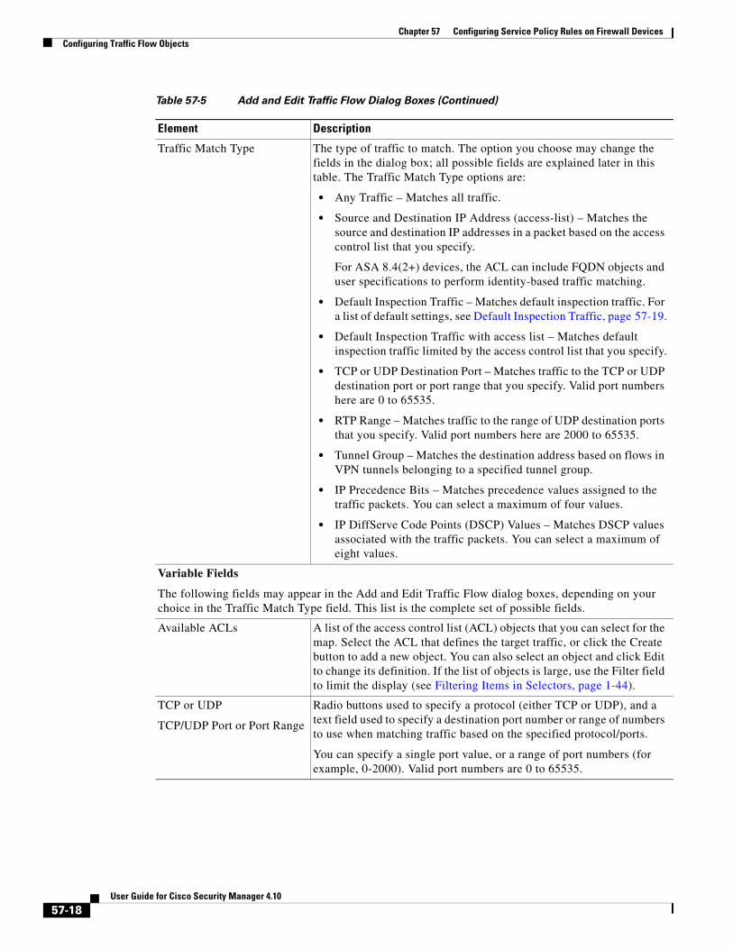
Traffic Match Type The type of traffic to match. The option you choose may change the fields in the dialog box; all possible fields are explained later in this table. The Traffic Match Type options are:
• Any Traffic – Matches all traffic.
• Source and Destination IP Address (access-list) – Matches the source and destination IP addresses in a packet based on the access control list that you specify.
For ASA 8.4(2+) devices, the ACL can include FQDN objects and user specifications to perform identity-based traffic matching.
• Default Inspection Traffic – Matches default inspection traffic. For a list of default settings, see Default Inspection Traffic, page 57-19.
• Default Inspection Traffic with access list – Matches default inspection traffic limited by the access control list that you specify.
• TCP or UDP Destination Port – Matches traffic to the TCP or UDP destination port or port range that you specify. Valid port numbers here are 0 to 65535.
• RTP Range – Matches traffic to the range of UDP destination ports that you specify. Valid port numbers here are 2000 to 65535.
• Tunnel Group – Matches the destination address based on flows in VPN tunnels belonging to a specified tunnel group.
• IP Precedence Bits – Matches precedence values assigned to the traffic packets. You can select a maximum of four values.
• IP DiffServe Code Points (DSCP) Values – Matches DSCP values associated with the traffic packets. You can select a maximum of eight values.
Variable Fields
The following fields may appear in the Add and Edit Traffic Flow dialog boxes, depending on your choice in the Traffic Match Type field. This list is the complete set of possible fields.
Available ACLs A list of the access control list (ACL) objects that you can select for the map. Select the ACL that defines the target traffic, or click the Create button to add a new object. You can also select an object and click Edit to change its definition. If the list of objects is large, use the Filter field to limit the display (see Filtering Items in Selectors, page 1-44).
TCP or UDP
TCP/UDP Port or Port Range
Radio buttons used to specify a protocol (either TCP or UDP), and a text field used to specify a destination port number or range of numbers to use when matching traffic based on the specified protocol/ports.
You can specify a single port value, or a range of port numbers (for example, 0-2000). Valid port numbers are 0 to 65535.
Table 57-5 Add and Edit Traffic Flow Dialog Boxes (Continued)
Element Description
57-18User Guide for Cisco Security Manager 4.10
Chapter 57 Configuring Service Policy Rules on Firewall DevicesConfiguring Traffic Flow Objects
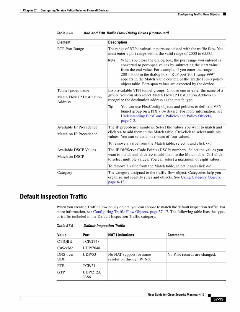
Default Inspection Traffic When you create a Traffic Flow policy object, you can choose to match the default inspection traffic. For more information, see Configuring Traffic Flow Objects, page 57-17. The following table lists the types of traffic included in the Default Inspection Traffic category.
RTP Port Range The range of RTP destination ports associated with the traffic flow. You must enter a port range within the valid range of 2000 to 65535.
Note When you close the dialog box, the port range you entered is converted to port-span values by subtracting the start value from the end value. For example, if you enter the range 2001-3000 in the dialog box, “RTP port 2001 range 999” appears in the Match Value column of the Traffic Flows policy object table. Port-span values are expected by the device.
Tunnel group name
Match Flow IP Destination Address
Lists available VPN tunnel groups. Choose one or enter the name of a group. You can also select Match Flow IP Destination Address to recognize the destination address as the match type.
Tip You can use FlexConfig objects and policies to define a VPN tunnel group on a PIX 7.0+ device. For more information, see Understanding FlexConfig Policies and Policy Objects, page 7-2.
Available IP Precedence
Match on IP Precedence
The IP precedence numbers. Select the values you want to match and click >> to add them to the Match table. Ctrl-click to select multiple values. You can select a maximum of four values.
To remove a value from the Match table, select it and click <<.
Available DSCP Values
Match on DSCP
The IP DiffServe Code Points (DSCP) numbers. Select the values you want to match and click >> to add them to the Match table. Ctrl-click to select multiple values. You can select a maximum of eight values.
To remove a value from the Match table, select it and click <<.
Category The category assigned to the traffic-flow object. Categories help you organize and identify rules and objects. See Using Category Objects, page 6-13.
Table 57-5 Add and Edit Traffic Flow Dialog Boxes (Continued)
Element Description
Table 57-6 Default Inspection Traffic
Value Port NAT Limitations Comments
CTIQBE TCP/2748
CuSeeMe UDP/7648
DNS over UDP
UDP/53 No NAT support for name resolution through WINS.
No PTR records are changed.
FTP TCP/21
GTP UDP/2123, 3386
57-19User Guide for Cisco Security Manager 4.10
Chapter 57 Configuring Service Policy Rules on Firewall DevicesConfiguring Traffic Flow Objects
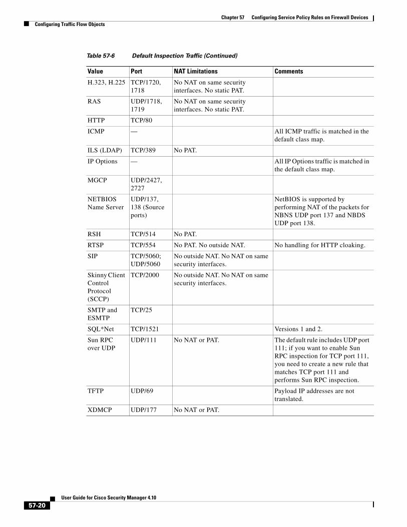
H.323, H.225 TCP/1720, 1718
No NAT on same security interfaces. No static PAT.
RAS UDP/1718, 1719
No NAT on same security interfaces. No static PAT.
HTTP TCP/80
ICMP — All ICMP traffic is matched in the default class map.
ILS (LDAP) TCP/389 No PAT.
IP Options — All IP Options traffic is matched in the default class map.
MGCP UDP/2427, 2727
NETBIOS Name Server
UDP/137, 138 (Source ports)
NetBIOS is supported by performing NAT of the packets for NBNS UDP port 137 and NBDS UDP port 138.
RSH TCP/514 No PAT.
RTSP TCP/554 No PAT. No outside NAT. No handling for HTTP cloaking.
SIP TCP/5060; UDP/5060
No outside NAT. No NAT on same security interfaces.
Skinny Client Control Protocol (SCCP)
TCP/2000 No outside NAT. No NAT on same security interfaces.
SMTP and ESMTP
TCP/25
SQL*Net TCP/1521 Versions 1 and 2.
Sun RPC over UDP
UDP/111 No NAT or PAT. The default rule includes UDP port 111; if you want to enable Sun RPC inspection for TCP port 111, you need to create a new rule that matches TCP port 111 and performs Sun RPC inspection.
TFTP UDP/69 Payload IP addresses are not translated.
XDMCP UDP/177 No NAT or PAT.
Table 57-6 Default Inspection Traffic (Continued)
Value Port NAT Limitations Comments
57-20User Guide for Cisco Security Manager 4.10
Chapter 57 Configuring Service Policy Rules on Firewall DevicesConfiguring TCP Maps
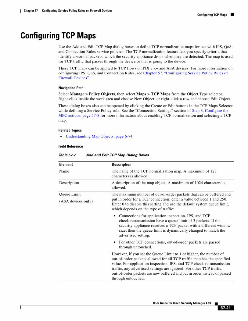
Configuring TCP MapsUse the Add and Edit TCP Map dialog boxes to define TCP normalization maps for use with IPS, QoS, and Connection Rules service policies. The TCP normalization feature lets you specify criteria that identify abnormal packets, which the security appliance drops when they are detected. The map is used for TCP traffic that passes through the device or that is going to the device.
These TCP maps can be applied to TCP flows on PIX 7.x+ and ASA devices. For more information on configuring IPS, QoS, and Connection Rules, see Chapter 57, “Configuring Service Policy Rules on Firewall Devices”.
Navigation Path
Select Manage > Policy Objects, then select Maps > TCP Maps from the Object Type selector. Right-click inside the work area and choose New Object, or right-click a row and choose Edit Object.
These dialog boxes also can be opened by clicking the Create or Edit buttons in the TCP Maps Selector while defining a Service Policy rule. See the “Connection Settings” section of Step 3. Configure the MPC actions, page 57-8 for more information about enabling TCP normalization and selecting a TCP map.
Related Topics
• Understanding Map Objects, page 6-74
Field Reference
Table 57-7 Add and Edit TCP Map Dialog Boxes
Element Description
Name The name of the TCP normalization map. A maximum of 128 characters is allowed.
Description A description of the map object. A maximum of 1024 characters is allowed.
Queue Limit
(ASA devices only)
The maximum number of out-of-order packets that can be buffered and put in order for a TCP connection; enter a value between 1 and 250. Enter 0 to disable this setting and use the default system queue limit, which depends on the type of traffic:
• Connections for application inspection, IPS, and TCP check-retransmission have a queue limit of 3 packets. If the security appliance receives a TCP packet with a different window size, then the queue limit is dynamically changed to match the advertised setting.
• For other TCP connections, out-of-order packets are passed through untouched.
However, if you set the Queue Limit to 1 or higher, the number of out-of-order packets allowed for all TCP traffic matches the specified value. For application inspection, IPS, and TCP check-retransmission traffic, any advertised settings are ignored. For other TCP traffic, out-of-order packets are now buffered and put in order instead of passed through untouched.
57-21User Guide for Cisco Security Manager 4.10
Chapter 57 Configuring Service Policy Rules on Firewall DevicesConfiguring TCP Maps
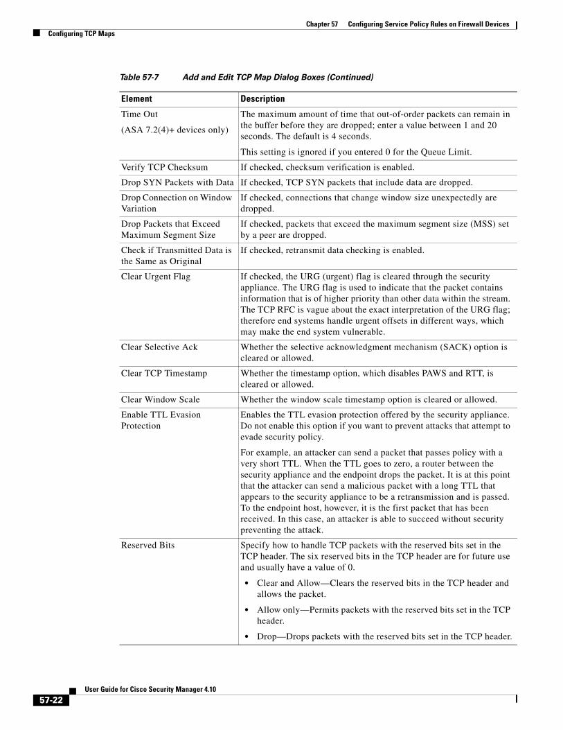
Time Out
(ASA 7.2(4)+ devices only)
The maximum amount of time that out-of-order packets can remain in the buffer before they are dropped; enter a value between 1 and 20 seconds. The default is 4 seconds.
This setting is ignored if you entered 0 for the Queue Limit.
Verify TCP Checksum If checked, checksum verification is enabled.
Drop SYN Packets with Data If checked, TCP SYN packets that include data are dropped.
Drop Connection on Window Variation
If checked, connections that change window size unexpectedly are dropped.
Drop Packets that Exceed Maximum Segment Size
If checked, packets that exceed the maximum segment size (MSS) set by a peer are dropped.
Check if Transmitted Data is the Same as Original
If checked, retransmit data checking is enabled.
Clear Urgent Flag If checked, the URG (urgent) flag is cleared through the security appliance. The URG flag is used to indicate that the packet contains information that is of higher priority than other data within the stream. The TCP RFC is vague about the exact interpretation of the URG flag; therefore end systems handle urgent offsets in different ways, which may make the end system vulnerable.
Clear Selective Ack Whether the selective acknowledgment mechanism (SACK) option is cleared or allowed.
Clear TCP Timestamp Whether the timestamp option, which disables PAWS and RTT, is cleared or allowed.
Clear Window Scale Whether the window scale timestamp option is cleared or allowed.
Enable TTL Evasion Protection
Enables the TTL evasion protection offered by the security appliance. Do not enable this option if you want to prevent attacks that attempt to evade security policy.
For example, an attacker can send a packet that passes policy with a very short TTL. When the TTL goes to zero, a router between the security appliance and the endpoint drops the packet. It is at this point that the attacker can send a malicious packet with a long TTL that appears to the security appliance to be a retransmission and is passed. To the endpoint host, however, it is the first packet that has been received. In this case, an attacker is able to succeed without security preventing the attack.
Reserved Bits Specify how to handle TCP packets with the reserved bits set in the TCP header. The six reserved bits in the TCP header are for future use and usually have a value of 0.
• Clear and Allow—Clears the reserved bits in the TCP header and allows the packet.
• Allow only—Permits packets with the reserved bits set in the TCP header.
• Drop—Drops packets with the reserved bits set in the TCP header.
Table 57-7 Add and Edit TCP Map Dialog Boxes (Continued)
Element Description
57-22User Guide for Cisco Security Manager 4.10
Chapter 57 Configuring Service Policy Rules on Firewall DevicesConfiguring TCP Maps
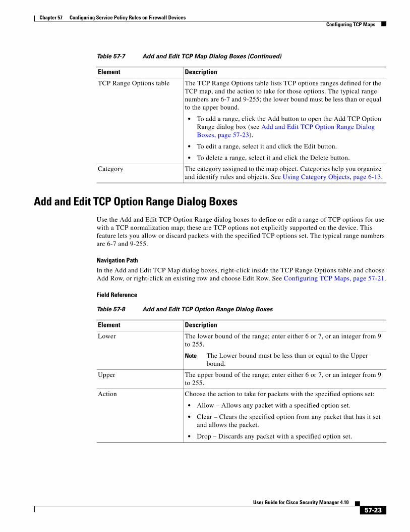
Add and Edit TCP Option Range Dialog BoxesUse the Add and Edit TCP Option Range dialog boxes to define or edit a range of TCP options for use with a TCP normalization map; these are TCP options not explicitly supported on the device. This feature lets you allow or discard packets with the specified TCP options set. The typical range numbers are 6-7 and 9-255.
Navigation Path
In the Add and Edit TCP Map dialog boxes, right-click inside the TCP Range Options table and choose Add Row, or right-click an existing row and choose Edit Row. See Configuring TCP Maps, page 57-21.
Field Reference
TCP Range Options table The TCP Range Options table lists TCP options ranges defined for the TCP map, and the action to take for those options. The typical range numbers are 6-7 and 9-255; the lower bound must be less than or equal to the upper bound.
• To add a range, click the Add button to open the Add TCP Option Range dialog box (see Add and Edit TCP Option Range Dialog Boxes, page 57-23).
• To edit a range, select it and click the Edit button.
• To delete a range, select it and click the Delete button.
Category The category assigned to the map object. Categories help you organize and identify rules and objects. See Using Category Objects, page 6-13.
Table 57-7 Add and Edit TCP Map Dialog Boxes (Continued)
Element Description
Table 57-8 Add and Edit TCP Option Range Dialog Boxes
Element Description
Lower The lower bound of the range; enter either 6 or 7, or an integer from 9 to 255.
Note The Lower bound must be less than or equal to the Upper bound.
Upper The upper bound of the range; enter either 6 or 7, or an integer from 9 to 255.
Action Choose the action to take for packets with the specified options set:
• Allow – Allows any packet with a specified option set.
• Clear – Clears the specified option from any packet that has it set and allows the packet.
• Drop – Discards any packet with a specified option set.
57-23User Guide for Cisco Security Manager 4.10

Chapter 57 Configuring Service Policy Rules on Firewall DevicesConfiguring TCP Maps
57-24User Guide for Cisco Security Manager 4.10