configuring devices - cisco - global home page · configuring devices ... locations are set up in...
TRANSCRIPT

C H A P T E R
4-1Cisco Internet Streamer CDS 2.0-2.3 Software Configuration Guide
OL-13493-04
4Configuring Devices
This chapter discusses configuring locations and device groups for devices, and detailed instructions on configuring the different types of devices–CDSMs, SEs, and, SRs. This chapter presents the following major topics:
• Configuring Locations, page 4-1
• Configuring Device Groups, page 4-3
• Configuring the Service Engine, page 4-6
• Configuring the Service Router, page 4-87
• Configuring the CDSM, page 4-91
Configuring LocationsLocations are set up in the Internet Streaming CDSM to organize and group SEs into virtual networks for distribution of content through delivery services. For more information about locations, see the “Cisco CDS Topology” section on page 2-1.
Locations need to be configured before you can activate SEs and SRs and bring them online in the CDS network.
To create a new location or edit an existing one, do the following:
Step 1 Choose Devices > Locations. The Locations Table page is displayed (Figure 4-1).

4-2Cisco Internet Streamer CDS 2.0-2.3 Software Configuration Guide
OL-13493-04
Chapter 4 Configuring DevicesConfiguring Locations
Figure 4-1 Locations Table Page
Step 2 In the task bar, click the Create New Location icon. The Creating New Location page is displayed (Figure 4-2).
To edit a location, click the Edit icon next to the location name.
Figure 4-2 Creating New Location Page
Step 3 Enter the settings as appropriate. See Table 4-1 for a description of the fields.

4-3Cisco Internet Streamer CDS 2.0-2.3 Software Configuration Guide
OL-13493-04
Chapter 4 Configuring DevicesConfiguring Device Groups
Step 4 Click Submit to save the settings.
To delete a location, from the Locations Table page, click the Edit icon next to the location you want to delete, and click the Trash icon in the task bar.
To view the location tree, click the Location Trees icon in the task bar. The location tree represents the network topology you configured when you assigned a parent to each location.
Configuring Device GroupsThe Internet Streaming CDSM allows you to configure SEs into device groups so that the entire group of SEs is configured at one time. Device groups and SEs share the same configuration features and options.
This section covers creating, editing, and deleting device groups. For information on assigning devices to a device group, see the “Assigning Devices to Device Groups” section on page 4-9. All other configuration pages for a device group are covered in the “Configuring the Service Engine” section on page 4-6.
Note The last configuration submitted for the device, whether it is the device group configuration or the individual device configuration, is the configuration the device uses.
To create or edit a device group, do the following:
Step 1 Choose Devices > Device Groups. The Device Groups Table page is displayed (Figure 4-3).
Table 4-1 Location Fields
Field Description
Name Name of the location.
Parent Location Choose a location from the drop-down list. A location with no parent, None, is level 1. The location level is displayed after you choose a parent location.
Comments Enter any information about the location.

4-4Cisco Internet Streamer CDS 2.0-2.3 Software Configuration Guide
OL-13493-04
Chapter 4 Configuring DevicesConfiguring Device Groups
Figure 4-3 Device Groups Table Page
Step 2 In the task bar, click the Create New Device Group icon. The Creating New Device Group page is displayed (Figure 4-4).
To edit a device group, click the Edit icon next to the device group name.
Figure 4-4 Creating New Device Group Page
Step 3 In the Name field, enter the name of the device group. The name must be unique and should be a name that is useful in distinguishing the device group from the others in the CDS.
Step 4 Check the Automatically assign all newly activated devices to this group check box if applicable.
Step 5 Choose Regular Group to indicate this group is not used as a baseline for all SEs or choose Baseline Group and select the baseline type to define this group as a baseline for all SEs.

4-5Cisco Internet Streamer CDS 2.0-2.3 Software Configuration Guide
OL-13493-04
Chapter 4 Configuring DevicesConfiguring Device Groups
For information about baseline groups, see the “Baseline Groups” section on page 2-3.
Step 6 To customize the left panel menu for this device group, click the Select pages to hide from the menu for this device group arrow, and check the pages you want to hide. To collapse these settings, click the arrow again.
Use this feature to remove from view any configuration pages that you do not need for the device group.
Step 7 In the Comments field, enter any information about the device group.
Step 8 Click Submit to save the settings.
If you are editing this device group, you can view a list of all settings configured for this device group by clicking the Pages configured for this device group arrow. To collapse this information list, click the arrow again.
To delete a device group, click the Trash icon in the task bar.
Step 9 To assign SEs to the device group, choose Assignments > Devices. The Assignment table is displayed listing all SEs in the CDS.
Step 10 Click the Assign icon (blue cross mark) next to each SE name you want to assign to this group.
To assign all SEs, click Assign all Service Engines in the task bar.
Step 11 Click Submit to add the selected SEs to the device group.
To remove an SE from the device group, click the Unassign icon (green check mark) next to the name of the SE, and click Submit.
To remove all SEs from the device group, click the Unassign all Service Engines icon in the task bar, and click Submit.
Note All configuration settings for a device group can be configured on an individual SE as well. All other configuration pages for a device group are covered in the “Configuring the Service Engine” section on page 4-6.
Device Group OverlapIf you want the ability to assign a device to more than one device group, you must enable device group overlap. Device group overlap is enabled by default.
To enable or disable device group overlap, do the following:
Step 1 Choose System > Configuration. The Config Properties page is displayed.
Step 2 Click the Edit icon next to the DeviceGroup.overlap property. The Modifying Config Property page is displayed.
Step 3 To enable device group overlap, choose true from the Value drop-down list.
To disable device group overlap, choose false from the Value drop-down list.
Step 4 Click Submit to save the settings.

4-6Cisco Internet Streamer CDS 2.0-2.3 Software Configuration Guide
OL-13493-04
Chapter 4 Configuring DevicesConfiguring the Service Engine
If you disable device group overlap after you have assigned devices to multiple device groups, existing overlaps are maintained. Any newly added groups will not allow assignment of devices that are already assigned to another group, and new devices cannot be added to any groups with overlapping devices.
Tip To force the complete configuration set of a device group to all devices in that group, click the Force Group Settings icon in the task bar.
Configuring the Service EngineThis section walks you through the different configuration pages available for a Service Engine. The main configuration groups are described as follows:
• Service Control—Settings for access control by way of client request filtering, URL signing, and third-party QoS and conditional access policies; additionally, transaction logs are configured to monitor traffic
• Application Control—Settings for bandwidth management of delivery services and protocol engines (Web, Windows Media, Movie Streamer, Flash Media Streaming, and RTSP advanced settings)
• General Settings—Settings for access control of the device, maintenance, network connectivity, and monitoring
The first two pages, Device Activation and Assignment, cover activating an SE in the Internet Streaming CDSM and assigning it to a location, and assigning device groups to the SE.
Note All SE settings in this section, except those listed below, can also be configured for a device group by choosing Devices > Device Groups. The following pages are not available for device group configuration:
• Devices > Application Control > Windows Media Streaming > Bypass List. See the “Configuring Windows Media Streaming—Bypass List” section on page 4-39 for more information.
• Devices > General Settings > Network > Network Interfaces. See the “Viewing Network Interfaces” section on page 4-61 for more information.
• Devices > General Settings > Network > External IP. See the “Configuring External IP Addresses” section on page 4-61 for more information.
Activating a Service EngineActivating a device (Service Engine, Service Router, or CDSM) can be done through the Device home page initially, or through the Device Activation page.
To activate a device from the Device Activation page, do the following:
Step 1 Choose Devices > Devices. The Devices Table page is displayed (Figure 4-5).

4-7Cisco Internet Streamer CDS 2.0-2.3 Software Configuration Guide
OL-13493-04
Chapter 4 Configuring DevicesConfiguring the Service Engine
Figure 4-5 Devices Table Page
Step 2 Click the Edit icon next to the device you want to configure. The Device home page is displayed.
Step 3 Click Show All to display the top-level menu options, and click Device Activation. The Device Activation page is displayed (Figure 4-6).
Figure 4-6 Device Activation Page

4-8Cisco Internet Streamer CDS 2.0-2.3 Software Configuration Guide
OL-13493-04
Chapter 4 Configuring DevicesConfiguring the Service Engine
Step 4 Enter the settings as appropriate. See Table 4-2 for a description of the fields.
Table 4-2 Device Activation Fields
Field Description
Name Name of the device.
Activate To activate or deactivate the device, check or uncheck the Activate check box.
Server Offload To offload this device for maintenance or a software upgrade, check the Server Offload check box. When checked, the Service Router stops sending requests to this device.
Note If a client paused a program at that moment Server Offload is enabled, most likely resuming the program will fail.
To monitor the current streams on an SE during the Server Offload state, use the show interface command. If the packets received or packets sent is increasing then the SE is streaming. Packets received will be high if there is an incoming stream.
Note We recommend separating the management traffic from the streaming traffic by using the port channel configuration, see the “Configuring Port Channel” section on page E-1 for more information.
1. If management and streaming traffic are separated, the show interface command for the streaming port channel displays information on active sessions.
2. If management and streaming traffic are not separated, the show interface command shows very low traffic; the packets received and packets sent are lower than a client streaming session.
Once the SE has finished streaming, you can perform maintenance or upgrade the software on the device. For information about upgrading the software, see the “Upgrading the Software” section on page 8-6.
The Status field on the Device Activation page and the Devices Table page displays “offloading” when Server Offload is checked.
Once the software upgrade or maintenance is complete, you need to uncheck the Server Offload check box so that the device can again participate in the system.
Note If the Server Offload option is set on an SE that is acting as the Content Acquirer for a delivery service for dynamic ingest or live stream splitting, a new SE is chosen as the Location Leader for the delivery service. However, if the Content Acquirer is up and communicating with the CDSM, it continues to perform content ingest and content distribution.
Content Cache Informational only. The content cache size is the total disk space on the CDS network file system (CDNFS) on the SE that is designated for cache. The Content Cache represents the unused cache space. The used cache space is the disk space allotted for all the delivery services to which the SE is assigned. To view the used cache space, choose Services > Service Definition > Delivery Services > Assign Service Engines.

4-9Cisco Internet Streamer CDS 2.0-2.3 Software Configuration Guide
OL-13493-04
Chapter 4 Configuring DevicesConfiguring the Service Engine
Step 5 Click Submit to save the settings.
Assigning Devices to Device GroupsYou can assign devices to device groups in three ways:
• Through the Device Group Assignment page
Set Default Coverage Zone File
When checked, which is the default setting, a default Coverage Zone file is generated with the SE serving the local subnet it resides on. The coverage zone is a CDS network-wide mapping of client IP addresses to SE IP addresses that should respond to client requests. For more information, see the “Coverage Zone File Registration” section on page 6-9.
The default coverage zone can be disabled and you can create and assign custom coverage zones using the Coverage Zone file import or upload.
Uncheck the Set Default Coverage Zone File check box to use a user-defined Coverage Zone file that was imported or uploaded.
Location Lists all the locations configured for the CDS.
Use SE’s primary IP address
Enables the CDSM to use the IP address on the primary interface of the SE for management communications.
Note If the Use SE’s primary IP Address for Management Communication check box is checked and the Management Communication Address and Port are configured, the CDSM uses the SE’s primary IP address for communication. If communication attempts to the primary address fail, the CDSM tries the configured IP address and port.
Note Do not check the Use SE’s primary IP Address for Management Communication check box if you want to separate management and streaming traffic. Instead, use the Management Communication Address and Port fields to specify where management traffic should be sent.
Management Communication Address
Manually configures a management IP address for the CDSM to communicate with the SE.
Note This is a Release 2.1 feature.
Manual configuration of the management IP address and port are used when using port channel configuration to separate management and streaming traffic. For more information about port channel configuration see the “Configuring Port Channel and Load Balancing Settings” section on page 4-62 and the “Configuring Port Channel” section on page E-1.
Management Communication Port
Port number to enable communication between the CDSM and the SE.
Note This is a Release 2.1 feature.
Comments Information about the settings.
Table 4-2 Device Activation Fields (continued)
Field Description

4-10Cisco Internet Streamer CDS 2.0-2.3 Software Configuration Guide
OL-13493-04
Chapter 4 Configuring DevicesConfiguring the Service Engine
• Through the device Assignment page
• Through the Device home page, if the device group is a baseline group
To assign devices to device groups through the Assignment page, do the following:
Step 1 Choose Devices > Devices, and click the Edit icon next to the device you want to assign.
Step 2 Click Show All, and then click Assignments > Device Groups. The Assignment page is displayed (Figure 4-7).
Figure 4-7 Assignment Page
Step 3 Choose Assignments > Device Groups. The Device Group Table page is displayed with all of the configured device groups listed.
Step 4 Click the Assign icon (blue cross mark) next to the device group you want to assign to this SE. Alternatively, click the Assign All Device Groups icon in the task bar.
A green arrow wrapped around the blue X indicates an SE assignment is ready to be submitted. To unassign an SE, click this icon.
Step 5 Click Submit to save the settings.
A green circle with a check mark indicates a device group is assigned to this SE. To unassign the device group, click this icon, or click the Unassign All Device Groups icon in the task bar. Click Submit to save the changes.
Note From this point forward, the beginning steps in the procedures are combined into one step using notation similar to the following: Devices > Devices Assignments > Device Groups.
Configuring Bandwidth for Replication and IngestThe bandwidth used for replication and ingest is determined by the settings in the Default Bandwidth and the Scheduled Bandwidth pages. The replication configuration pages consist of the following:
• Default Bandwidth

4-11Cisco Internet Streamer CDS 2.0-2.3 Software Configuration Guide
OL-13493-04
Chapter 4 Configuring DevicesConfiguring the Service Engine
• Scheduled Bandwidth
Default Bandwidth
The default bandwidth settings can be configured for acquisition (ingest) and distribution (replication) of content. The default settings are used unless a scheduled bandwidth is configured for a specified time period.
To set the default bandwidth for replication, do the following:
Step 1 Choose Devices > Devices > Replication > Default Bandwidth. The Replication Default Bandwidth page is displayed (Figure 4-8).
Figure 4-8 Replication Default Bandwidth Page
Step 2 Enter the settings as appropriate. See Table 4-3 for a description of the fields.
Step 3 Click Submit to save the settings.
Table 4-3 Replication Default Bandwidth Fields
Field Description
Acquisition-in Bandwidth
Bandwidth used for ingesting content when this SE is acting as the Content Acquirer.
The default is 500000 kbps (kilobits per second) .
Distribution-in Bandwidth
Bandwidth used for incoming content that is sent by a forwarding SE as part of the distribution process.
The default is 250000 kbps.
Distribution-out Bandwidth
Bandwidth used for outgoing content that is sent to a downstream SE as part of the distribution process.
The default is 500000 kbps.

4-12Cisco Internet Streamer CDS 2.0-2.3 Software Configuration Guide
OL-13493-04
Chapter 4 Configuring DevicesConfiguring the Service Engine
Bandwidth Graph
To view a graphical representation of the bandwidth settings, click the Display Graph icon in the task bar. The Acquisition and Distribution Bandwidth graph is displayed in a new window.
The vertical axis of the graph represents the amount of bandwidth in Kbps (kilobits per second) and the horizontal axis represents the days of the week. The scale shown on the vertical axis is determined dynamically based on the bandwidth rate for a particular type of bandwidth and is incremented appropriately. The scale shown on the horizontal axis for each day is incremented for each hour. Each type of bandwidth is represented by a unique color. A legend at the bottom of the graph maps the colors to the corresponding bandwidths.
You can change the graph view by choosing the different options, as described in Table 4-4.
Scheduled Bandwidth
Scheduled Bandwidth settings take precedence over Default Bandwidth settings.
To configure a bandwidth schedule, do the following:
Step 1 Choose Devices > Devices > Replication > Scheduled Bandwidth. The Replication Scheduled Bandwidth Table page is displayed (Figure 4-9).
Table 4-4 Acquisition and Distribution Bandwidth Graph—Viewing Options
Option Description
Distribution In Bandwidth settings for incoming content distribution traffic.
Distribution Out Bandwidth settings for outgoing content distribution traffic.
Acquisition In Bandwidth settings for incoming content acquisition traffic.
All Servers A consolidated view of all configured bandwidth types. This is the default.
Show Detailed Bandwidth/Show Effective Bandwidth
Toggles between the two options:
Show Detailed Bandwidth—Displays detailed bandwidth settings for the SE and its associated device groups. The bandwidth settings of the device and device groups are shown in different colors for easy identification.
Show Effective Bandwidth—Displays the composite (aggregate) bandwidth settings for the SE and its associated device groups.
Show Aggregate View/Show Non-Aggregate View
Toggles between the two options:
Show Aggregate View—Displays the bandwidth settings configured for the corresponding device groups.
Show non-Aggregate View—Displays the bandwidth settings configured for the SE.
Sun, Mon, Tues, Wed, Thurs, Fri, Sat
Displays the bandwidth settings for the corresponding day of the week.
Full Week Displays the bandwidth settings for the entire week This is the default view and is combined with the All Servers view.

4-13Cisco Internet Streamer CDS 2.0-2.3 Software Configuration Guide
OL-13493-04
Chapter 4 Configuring DevicesConfiguring the Service Engine
Figure 4-9 Replication Scheduled Bandwidth Table Page
Step 2 Aggregate Settings is set to Yes by default. If this SE belongs to a device group, and the settings have not been configured using the device group, you can enter the settings and they will apply to the device group as well.
If the settings are previously configured through the device group, the current configuration is displayed for view only. New settings must be configured through the associated device group.
If you want to configure settings for this SE only, and override the device group settings on this SE, set Aggregate Settings to No.
If you remove all device group settings, all device settings displayed with Aggregate Settings enabled are removed as well.
Note The last configuration submitted for the device, whether it is the device group configuration or the individual device configuration, is the configuration the device uses.
Step 3 Click the Create New icon in the task bar. The Replication Scheduled Bandwidth page is displayed (Figure 4-10).
To edit a scheduled bandwidth, click the Edit icon next to the scheduled bandwidth you want to edit.

4-14Cisco Internet Streamer CDS 2.0-2.3 Software Configuration Guide
OL-13493-04
Chapter 4 Configuring DevicesConfiguring the Service Engine
Figure 4-10 Replication Scheduled Bandwidth Page
Step 4 Enter the settings as appropriate. See Table 4-5 for a description of the fields.
Step 5 Click Submit to save the settings.
Service ControlThe Service Control pages provide settings for client request filtering, URL signing, and third-party QoS and conditional access policies. Additionally, transaction logs that monitor traffic are configured under the Service Control. Configuring service control consists of the following procedures:
• Configuring Service Rules
• Configuring ICAP
Table 4-5 Replication Scheduled Bandwidth Fields
Field Description
Bandwidth Type Distribution-in—For incoming content distribution traffic from SEs.
Distribution-out—For outgoing content distribution traffic to SEs.
Acquisition-in—For incoming content acquisition traffic from origin servers.
Bandwidth Rate Maximum amount of bandwidth that you want to allow (in kbps).
Start Time Time of day for the bandwidth setting to begin, using a 24-hour clock in local time (hh:mm).
End Time Time of day for the bandwidth setting to end (hh:mm).
Day Selection Days on which bandwidth settings apply.
• Full Week—Specifies that the allowable bandwidth settings are applied for an entire week.
• Sun, Mon, Tue, Wed, Thu, Fri, and Sat—Specifies individual days of the week on which the allowable bandwidth settings take effect.

4-15Cisco Internet Streamer CDS 2.0-2.3 Software Configuration Guide
OL-13493-04
Chapter 4 Configuring DevicesConfiguring the Service Engine
• Configuring PCMM QoS Policy
• Configuring URL Signing
• Configuring Transaction Logs
Configuring Service Rules
Note This is a licensed feature. Please ensure that you have purchased a Service Rule license for this advanced feature.
The Rules Template licensed feature provides a flexible mechanism to specify configurable caching requests by allowing these requests to be matched against an arbitrary number of parameters, with an arbitrary number of policies applied against the matches. You can specify a set of rules, each clearly identified by an action and a pattern. Subsequently, for every incoming request, if a pattern for a rule matches the given request, the corresponding action for that rule is taken.
Note The processing time on the SE is directly related to the number of service rules configured. Processing times increase with an increase in the total number of rules configured. If the SE processing time is greater than twice the datafeed poll rate, then the device goes offline until the processing is completed. You can avoid this by configuring a higher datafeed poll rate. The recommended datafeed poll rate for 750 service rules is 300 seconds. To configure the datafeed poll rate, see the “Configuring System Settings” section on page 6-6.
Configuring a service rule consists of the following tasks:
• Enabling the service rules. (Only needs to be performed once.)
• Configuring a pattern list and adding a pattern to it.
• Associating an action with an existing pattern list.
To configure or edit service rule settings, do the following:
Step 1 Choose Devices > Devices > Service Control > Enable Rules. The Enable Service Rules page is displayed.
Step 2 Check the Enable check box to enable the use of rule settings.
Step 3 Click Submit to save the settings.
Step 4 Choose Devices > Devices > Service Control > Service Rules. The Service Rules Table page is displayed.
Step 5 Aggregate Settings is set to Yes by default. If this SE belongs to a device group, and the settings have not been configured using the device group, you can enter the settings and they will apply to the device group as well.
If the settings are previously configured through the device group, the current configuration is displayed for view only. New settings must be configured through the associated device group.
If you want to configure settings for this SE only, and override the device group settings on this SE, set Aggregate Settings to No.
If you remove all device group settings, all device settings displayed with Aggregate Settings enabled are removed as well.

4-16Cisco Internet Streamer CDS 2.0-2.3 Software Configuration Guide
OL-13493-04
Chapter 4 Configuring DevicesConfiguring the Service Engine
Note The last configuration submitted for the device, whether it is the device group configuration or the individual device configuration, is the configuration the device uses.
Step 6 Click the Create New icon in the task bar. The Service Rules page is displayed (Figure 4-11).
To edit a service rule, click the Edit icon next to the service rule you want to edit.
Figure 4-11 Service Rules Page
Step 7 Create a pattern list and add a pattern to it.
a. From the Rule Type drop-down list, choose pattern-list.
b. In the Rule Parameters field, configure the pattern list number and the pattern type, following the rules usage guidelines shown on the Service Rules page. See Table 4-6 for a description of pattern types. The rule patterns are not case-sensitive.
For example, to create pattern list number 72 with the pattern type domain and the yahoo.com domain as the domain to be acted on, enter 72 domain yahoo.com in the Rule Parameters field.

4-17Cisco Internet Streamer CDS 2.0-2.3 Software Configuration Guide
OL-13493-04
Chapter 4 Configuring DevicesConfiguring the Service Engine
Note A domain pattern list matching an SE IP address is not supported when IP-based redirection is enabled on the Service Router. Flash Media Streaming bypasses the rules configuration if the request is from another SE. See the “Configuring the Service Router” section on page 4-87 for more information about IP-based redirection.
Step 8 Click Submit to save the settings.
The maximum number of pattern lists allowed is 128.
Step 9 Associate an action with an existing pattern list.
a. Choose an action type from the Rule Type drop-down list. See Table 4-7 for a description of rule actions.
b. In the Rule Parameters field, enter the list number of the pattern list that you want to associate with this action.
For example, if you want to block access by any protocol to yahoo.com, then choose block from the Rule Type drop-down list, and enter pattern-list 72 protocol all in the Rule Parameters field.
Table 4-6 Service Rules Pattern Types
Pattern Type Description Syntax
domain Matches the domain name in the URL or the host header against a regular expression. For example, “.*ibm.*” matches any domain name that contains the “ibm” substring. “\.foo\.com$” matches any domain name that ends with the “.foo.com” substring.
In regular expression syntax, the dollar sign ($) metacharacter directs that a match is made only when the pattern is found at the end of a line.
rule pattern-list list_num domain dn_regexp
group-type Patterns can be combined by using the AND or OR function with the group-type pattern (for example, rule pattern-list 1group-type and). The default is OR.
rule pattern-list list-num group-type {and | or}
header-field Request header field pattern.
Request header field patterns referer, request-line, and user-agent are supported for the allow, block, and redirect actions. The referer pattern is matched against the Referer header in the request, the request-line pattern is matched against the first line of the request, and the user-agent pattern is matched against the User-Agent header in the request.
Note In Release 2.3, Flash Media Streaming supports the referer header field pattern for the allow and block actions.
rule pattern-list list_num header-field {referer ref_regexp | request-line req_regexp | user-agent ua_regexp}
scr-ip Matches the request’s source IP address and netmask. rule pattern-list list_num src-ip s_ipaddress s_subnet
url-regex Matches the URL against a regular expression. The match is not case sensitive.
rule pattern-list list_num url-regex url_regexp
url-regsub For the rewrite and redirect actions, matches the URL against a regular expression to form a new URL in accordance with the pattern substitution specification. The match is not case sensitive. The valid substitution index range is from 1 to 9.
rule pattern-list list_num url-regsub url_regexp url_sub

4-18Cisco Internet Streamer CDS 2.0-2.3 Software Configuration Guide
OL-13493-04
Chapter 4 Configuring DevicesConfiguring the Service Engine
Note Movie Streamer and Flash Media Streaming support URL signing in Release 2.2. Flash Media Streaming only supports the following actions: allow, block, and validate-url-signature.
Step 10 Click Submit to save the settings.
Table 4-7 Service Rule Actions
Action Type Description Syntax
allow Allows incoming requests that match the pattern list.
This rule action can be used in combination with block actions to allow selective types of requests. The allow action does not carry any meaning as a standalone action.
rule action allow pattern-list list_num [protocol {all | http | rtsp}]
block Blocks this request and allows all others. rule action block pattern-list list_num [protocol {all | http | rtsp}]
generate-url-signature
Generates the URL signatures in the Windows Media metafile response associated with prefetched content, based on the SE configuration for the URL signature and this rule action.
rule action generate-url-signature [include-client-src-ip] key-id-owner owner_num key-id-number id_num pattern-list list_num [protocol {all | http}]
no-cache Does not cache this object. rule action no-cache pattern-list list_num [protocol {all | http}]
redirect Redirects the original request to a specified URL. Redirect is relevant to the RADIUS server only if the RADIUS server has been configured for redirect.
rule action redirect url pattern-list list_num [protocol {all | http | rtsp}]
refresh For a cache hit, forces an object freshness check with the server. rule action refresh pattern-list list_num [protocol {all | http}]
rewrite Rewrites the original request as a specified URL. rule action rewrite pattern-list list_num [protocol {all | http | rtsp}]
use-icap-service Applies ICAP processing and uses a specific ICAP service only for those requests that match this Rules Template action.
An ICAP service is a collection of attributes that defines the type of modification to be performed on HTTP requests and responses. If this action is configured, you can allow requests and responses to be processed by ICAP servers for content adaptation.
rule action use-icap-service service-name pattern-list list_num [protocol {all | http}]
validate-url-signature
Validates the URL signature for a request using the configuration on your SE for the URL signature and allows the request processing to proceed for this request.
rule action validate-url-signature error-redirect-url url pattern-list list_num [protocol {all | http | rtsp}]

4-19Cisco Internet Streamer CDS 2.0-2.3 Software Configuration Guide
OL-13493-04
Chapter 4 Configuring DevicesConfiguring the Service Engine
Execution Order of Rule Actions
The order in which the rule actions are executed is as follows:
1. block or allow
Note The allow and block actions carry the same precedence. The order of execution depends on the order of configuration between allow and block actions. Other actions always take precedence over allow.
2. redirect (before cache lookup)
3. rewrite (before cache lookup)
4. refresh (after cache lookup, in the case of cache hit)
5. no-cache
6. use-icap-service
7. generate-url-signature
8. validate-url-signature
9. allow
Note When configuring service rules, you must configure the same service rules on all SEs participating in a delivery service in order for the service rules to be fully implemented. The rule action must be common for all client requests because the SR may redirect a client request to any SE in a delivery service depending on threshold conditions.
Configuring ICAP
The Internet Content Adaptation Protocol (ICAP) is an open-standards protocol that can be used for content adaptation. Content adaptation includes content translation, content filtering, and content insertion. ICAP specifies how the SE, acting as an HTTP proxy server, can communicate with an external server, which filters and adapts the requested content. This allows you to set up interoperability with Camiant PCMM-compliant third-party policy servers to allocate guaranteed bandwidth for authorized requests of content.
ICAP provides two content-processing modes for HTTP services. These modes define the transactions that can occur between an SE acting as an ICAP client and the external ICAP server. The two modes are as follows:
• Request modification (reqmod)—Allows modification of requests as they are sent from the SE to the ICAP server on their way to the origin server. The ICAP server can modify these requests depending on the content requested.
• Response modification (respmod)—Allows modification of requests after they return from the origin server. The ICAP server only acts on requested objects only after they return from the origin server.
An ICAP service is a collection of attributes that define the service and one or more ICAP servers that provide the ICAP services. You can configure a maximum of ten ICAP services per Content Engine, with an upper limit of five ICAP servers per ICAP service. Also, you can choose to apply ICAP services on all HTTP requests processed by the Content Engine or apply ICAP processing only to requests that match the Rules Template.
4-20Cisco Internet Streamer CDS 2.0-2.3 Software Configuration Guide
OL-13493-04
Chapter 4 Configuring DevicesConfiguring the Service Engine
Caution The maximum file size supported is 2 GB. Files that exceed this size limit are not supported for ICAP processing.
To configure ICAP settings, do the following:
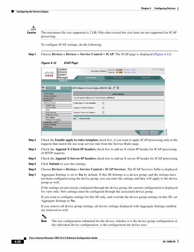
Step 1 Choose Devices > Devices > Service Control > ICAP. The ICAP page is displayed (Figure 4-12).
Figure 4-12 ICAP Page
Step 2 Check the Enable apply to rules-template check box, if you want to apply ICAP processing only to the requests that match the use-icap-service rule from the Service Rules page.
Step 3 Check the Append X-Client-IP headers check box to add an X-client-IP header for ICAP processing of HTTP requests.
Step 4 Check the Append X-Server-IP headers check box to add an X-server-IP header for ICAP processing.
Step 5 Click Submit to save the settings.
Step 6 Choose Devices > Devices > Service Control > ICAP Services. The ICAP Services Table is displayed.
Step 7 Aggregate Settings is set to Yes by default. If this SE belongs to a device group, and the settings have not been configured using the device group, you can enter the settings and they will apply to the device group as well.
If the settings are previously configured through the device group, the current configuration is displayed for view only. New settings must be configured through the associated device group.
If you want to configure settings for this SE only, and override the device group settings on this SE, set Aggregate Settings to No.
If you remove all device group settings, all device settings displayed with Aggregate Settings enabled are removed as well.
Note The last configuration submitted for the device, whether it is the device group configuration or the individual device configuration, is the configuration the device uses.
4-21Cisco Internet Streamer CDS 2.0-2.3 Software Configuration Guide
OL-13493-04
Chapter 4 Configuring DevicesConfiguring the Service Engine
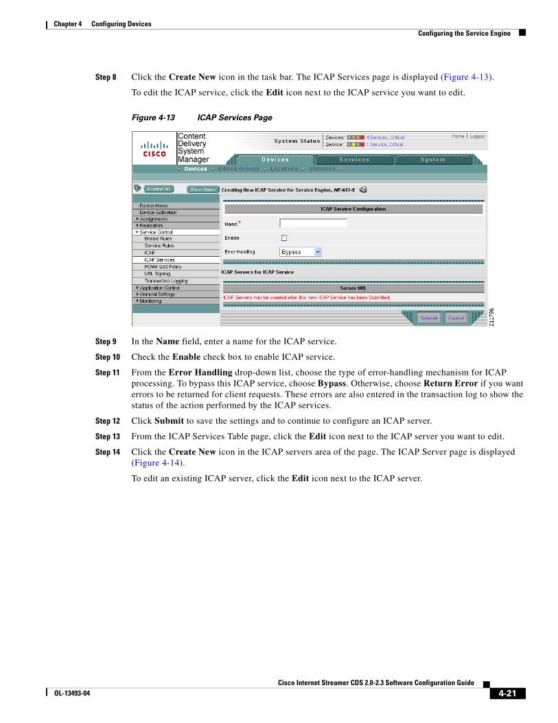
Step 8 Click the Create New icon in the task bar. The ICAP Services page is displayed (Figure 4-13).
To edit the ICAP service, click the Edit icon next to the ICAP service you want to edit.
Figure 4-13 ICAP Services Page
Step 9 In the Name field, enter a name for the ICAP service.
Step 10 Check the Enable check box to enable ICAP service.
Step 11 From the Error Handling drop-down list, choose the type of error-handling mechanism for ICAP processing. To bypass this ICAP service, choose Bypass. Otherwise, choose Return Error if you want errors to be returned for client requests. These errors are also entered in the transaction log to show the status of the action performed by the ICAP services.
Step 12 Click Submit to save the settings and to continue to configure an ICAP server.
Step 13 From the ICAP Services Table page, click the Edit icon next to the ICAP server you want to edit.
Step 14 Click the Create New icon in the ICAP servers area of the page. The ICAP Server page is displayed (Figure 4-14).
To edit an existing ICAP server, click the Edit icon next to the ICAP server.

4-22Cisco Internet Streamer CDS 2.0-2.3 Software Configuration Guide
OL-13493-04
Chapter 4 Configuring DevicesConfiguring the Service Engine
Figure 4-14 ICAP Server Page
Step 15 Enter the settings as appropriate. See Table 4-8 for a description of the fields.
Step 16 Click Submit to save the settings.
Configuring PCMM QoS Policy
The SE can interoperate with Camiant PCMM-compliant third-party policy servers to allocate guaranteed bandwidth for requests from authenticated clients.
Note This is a licensed feature. Please ensure you have purchased a PCMM license for this advanced feature.
Note To use this license-enabled feature, you must have a Camiant PCMM-compliant policy server in your network and it must be configured as an ICAP server. See the “Configuring ICAP” section on page 4-19 for more information.
Table 4-8 ICAP Server Fields
Field Description
Server Host Hostname or IP address of the ICAP server.
Server Port Port number on which the ICAP server is to be configured to process HTTP requests. The default port number is 1344. If no port number is specified, the default is used.
Server Service Name
Path to the ICAP server configured on the SE. Use the URL format:
icap://ICAPserverIPaddress:port/service-name.
The service name entered here must be supported by the ICAP vendor.

4-23Cisco Internet Streamer CDS 2.0-2.3 Software Configuration Guide
OL-13493-04
Chapter 4 Configuring DevicesConfiguring the Service Engine
To configure a PCMM QoS Policy, do the following:
Step 1 Choose Devices > Devices > Service Control > PCMM QoS Policy. The PCMM QoS Policy page is displayed (Figure 4-15).
Figure 4-15 PCMM QoS Policy Page
Step 2 Check the Enable check box to enable policy server settings for the device.
Step 3 Check the Set Config File or URL check box to specify the configuration file for the HTTP callout to the policy server.
The configuration file is an XML file that contains information on the callout URLs, attributes, application type, protocol, and so on.
Step 4 In the Config File or URL field, enter the filename or URL from which the SE can download the configuration file and click Fetch Config File Now. This field supports only URLs that use HTTP, HTTPS, or FTP.
Step 5 Click Submit to save the settings.
Configuring URL Signing
URL signature keys are word values that ensure URL-level security. The URL signature key is a shared secret between the device that assigns the key and the device that decrypts the key. Based on your network settings, either the SE itself or some other external device can assign the signature key to the URL, but the SE decrypts the URL signature key.
The CDS uses a combination of key owners, key ID numbers, and a word value to generate URL signature keys. You can have a maximum of 32 key owners. Each key owner can have up to 16 key ID numbers.
To create request-specific URL signature keys, you can choose to append the IP address of the client that has made the request to the URL signature key.

4-24Cisco Internet Streamer CDS 2.0-2.3 Software Configuration Guide
OL-13493-04
Chapter 4 Configuring DevicesConfiguring the Service Engine
To create a URL signature key, do the following:
Step 1 Choose Devices > Devices > Service Control > URL Signing. The URL Signing Table page is displayed.
Step 2 Aggregate Settings is set to Yes by default. If this SE belongs to a device group, and the settings have not been configured using the device group, you can enter the settings and they will apply to the device group as well.
If the settings are previously configured through the device group, the current configuration is displayed for view only. New settings must be configured through the associated device group.
If you want to configure settings for this SE only, and override the device group settings on this SE, set Aggregate Settings to No.
If you remove all device group settings, all device settings displayed with Aggregate Settings enabled are removed as well.
Note The last configuration submitted for the device, whether it is the device group configuration or the individual device configuration, is the configuration the device uses.
Step 3 Click the Create New icon in the task bar. The URL Signing page is displayed.
To edit the URL signature, click the Edit icon next to the URL Signature Key ID owner you want to edit.
Step 4 Enter the settings as appropriate. See Table 4-9 for a description of the fields.
Step 5 Click Submit to save the settings.
Service Rules for Directing Requests to a Policy Server
If your network is configured to work with Camiant PCMM-compliant third-party policy servers for servicing requests that require guaranteed bandwidth, you can use the following rule patterns and rule actions to filter the requests and to direct them to the policy server. The rule patterns and rule actions also enable you to generate URL signatures in the response for a valid request for a Windows Media
Table 4-9 URL Signature Key Settings
Field Description
Key ID Owner Specifies the ID number for the owner of this encryption key. Valid entries are from 1 to 32.
Key ID Specifies the encryption key ID number. Valid entries are from 1 to 16.
URL Signature Key Enters a unique URL signature key with up to 16 characters (excluding double quotes at the beginning and end of the string). This field does not support a space or the following special characters: pipe ( | ), question mark (?), double quotes ("), and apostrophe (’).
Quoted and unquoted strings are allowed. Double quotes (") are allowed at the beginning and end of the string only. If you do not surround the key string with double quotes, quotes will be added when you click Submit.

4-25Cisco Internet Streamer CDS 2.0-2.3 Software Configuration Guide
OL-13493-04
Chapter 4 Configuring DevicesConfiguring the Service Engine
metafile (.asx file extension), Movie Streamer file, or Flash Media Streaming file, and to validate the URL signature on incoming requests to the SE. For more information on creating service rules, see the “Configuring Service Rules” section on page 4-15.
URL signature key authentication is implemented by using the generate-url-signature and validate-url-signature rule actions that can be applied to specific rule patterns.
Note Movie Streamer and Flash Media Streaming support URL signing in Release 2.2. Flash Media Streaming only supports the following actions: allow, block, and validate-url-signature.
Table 4-10 lists the rule patterns that support the use-icap-service rule action for directing requests that require guaranteed bandwidth to the third-party policy server:
You can set the se-icap-service rule action for any of the rule patterns above. If the request matches the parameters that you have set for the rule pattern, then the SE redirects the request to the third-party policy server using ICAP services. However, you must make sure that your network is configured to interoperate with the third-party policy server using ICAP services. You can set up the necessary ICAP configurations from the ICAP Services page. See the “Configuring ICAP” section on page 4-19.
You can also use the rule pattern and rule action to generate URL signatures in the response for a valid request for a Windows Media metafile. You can use the following rule patterns to filter out requests for which you want to generate a URL signature key:
For the rule patterns mentioned above, you can set the following rule actions:
Table 4-10 Rule Patterns Supported for use-icap-service
Rule Pattern Description
url-regex Filters the request based on any regular expression n the URL.
domain Filters the request based on the domain name specified.
src-ip Filters the request based on the IP address of the source.
header-field user-agent Filters the request based on the user agent specified in the request header.
header-field referer Filters the request based on the referer in the request header.
header-field request-line Filters the request based on the request line in the request header.
Rule Pattern Description
url-regex Filters the request based on any regular expression in the URL.
domain Filters the request based on the domain name specified.
Rule Action Description
generate-url-signature Generates the URL signatures in the Windows Media metafile response associated with pre-positioned content, based on the SE configuration for the URL signature and this rule action.
validate-url-signature Validates the URL signature for a request by using the configuration on your SE for the URL signature and allows the request processing to proceed for this request

4-26Cisco Internet Streamer CDS 2.0-2.3 Software Configuration Guide
OL-13493-04
Chapter 4 Configuring DevicesConfiguring the Service Engine
Note When configuring service rules, you must configure the same service rules on all SEs participating in a delivery service in order for the service rules to be fully implemented. The rule action must be common for all client requests because the SR may redirect a client request to any SE in a delivery service depending on threshold conditions.
Configuring Transaction Logs
Transaction logs allow administrators to view the traffic that has passed through the SE. Typical fields in the transaction log are the date and time when a request was made, the URL that was requested, whether it was a cache hit or a cache miss, the type of request, the number of bytes transferred, and the source IP address. For more information about transaction logs and their formats, see the “Transaction Logs” section on page 7-31.
To enable transaction logging, do the following:
Step 1 Choose Devices > Devices > Service Control > Transaction Logs. The Transaction Log Settings page is displayed.
Step 2 Enter the settings as appropriate. See Table 4-11 for a description of the fields.
Table 4-11 Transaction Log Settings Fields
Field Description
General Settings
Transaction Log Enable Enables transaction logging.
Log Windows Domain If NTLM authentication is configured, you can record the Windows domain name and username in the “authenticated username” field of the transaction log by checking this check box. For more information, see the “Transaction Logging and NTLM Authentication” section on page 7-33.
Compress Files before Export When this check box is checked, archived log files are compressed into gzip format before being exported to external FTP servers
Log File Format
Log Format Custom
Log file format choices are extended-squid or apache. For more information, see the “Transaction Log Formats” section on page 7-31.
Or, choose Log Format Custom and enter a custom format string. For more information, see the “Custom Format” section on page 7-32.
Archive Settings
Max size of Archive File Maximum size (in kilobytes) of the archive file to be maintained on the local disk.
Max number of files to be archived
Maximum number of files to be maintained on the local disk.

4-27Cisco Internet Streamer CDS 2.0-2.3 Software Configuration Guide
OL-13493-04
Chapter 4 Configuring DevicesConfiguring the Service Engine
Archive occurs How often the working log is archived and the data is cleared from the working log. Choose one of the following:
Choose every to archive every so many seconds, and enter the number of seconds for the interval.
Choose every hour to archive using intervals of one hour or less, and choose one of the following:
• at—Specifies the minute in which each hourly archive occurs
• every—Specifies the number of minutes for the interval (2, 5, 10, 15, 20, or 30)
Choose every day to archive using intervals of one day or less, and choose one of the following:
• at—Specifies the hour in which each daily archive occurs
• every—Specifies the number of hours for the interval (1, 2, 3, 4, 6, 8, 12, 24)
Choose every week on to archive at intervals of one or more times a week, choose the days of the week, and choose what time each day.
Export Settings
Enable Export Enables exporting of the transaction log to an FTP server.
Export occurs How often the working log is sent to the FTP server and the data is cleared from the working log. Choose one of the following:
Choose every to export every so many seconds, and enter the number of seconds for the interval.
Choose every hour to export using intervals of one hour or less, and choose one of the following:
• at—Specifies the minute in which each hourly export occurs
• every—Specifies the number of minutes for the interval (2, 5, 10, 15, 20, or 30)
Choose every day to export using intervals of one day or less, and choose one of the following:
• at—Specifies the hour in which each daily export occurs
• every—Specifies the number of hours for the interval (1, 2, 3, 4, 6, 8, 12, 24)
Choose every week on to export using intervals of one or more times a week, choose the days of the week, and what time each day.
Export Server IP address or hostname of the FTP server.
Name Name of the user.
Password Password for the user.
Confirm Password Confirms the password for the user.
Directory Name of the directory used to store the transaction logs on the FTP server.
Table 4-11 Transaction Log Settings Fields (continued)
Field Description

4-28Cisco Internet Streamer CDS 2.0-2.3 Software Configuration Guide
OL-13493-04
Chapter 4 Configuring DevicesConfiguring the Service Engine
Step 3 Click Submit to save the settings.
Application ControlThe Application Control pages provide settings for bandwidth management of delivery services and protocol engines. Configuring application control consists of the following procedures:
• Configuring Default and Maximum Bandwidth
• Configuring Bandwidth Schedules
• Configuring Windows Media Streaming—General Settings
Windows Media Settings
Enable Windows Media Settings
Enables Windows Media transaction logging.
Log File Format Sets Windows Media Streaming Engine to generate transaction logs in the following formats:
• extended wms-41
Uses the standard Windows Media Services 4.1 format to generate the transaction log and includes the following three additional fields in the transaction log:
• SE_action (cache hit or cache miss)
• SE-bytes (number of bytes sent from the SE for a cache hit)
• username (username of the Windows Media request when NTLM, Negotiate, Digest, or basic authentication is used)
• extended wms-90
Uses the standard Windows Media Services 9 format to generate the transaction log and includes the following three additional fields in the transaction log:
• SE_action (cache hit or cache miss)
• SE-bytes (number of bytes sent from the Service Engine for a cache hit)
• username (username of the Windows Media request when NTLM, Negotiate, Digest, or basic authentication is used)
• wms-41 Standard Windows Media Services 4.1 format.
• wms-90 Standard Windows Media Services 9 format.
For more information, see the “Windows Media Transaction Logging” section on page 7-35.
Table 4-11 Transaction Log Settings Fields (continued)
Field Description

4-29Cisco Internet Streamer CDS 2.0-2.3 Software Configuration Guide
OL-13493-04
Chapter 4 Configuring DevicesConfiguring the Service Engine
• Configuring Windows Media Streaming Multicast Station
• Configuring Windows Media Streaming Multicast Station Schedule
• Configuring Windows Media Streaming—Broadcast Alias
• Configuring Windows Media Streaming—Bypass List
• Configuring Movie Streamer—General Settings
• Configuring RTSP Advanced Settings
• Configuring Flash Media Streaming
• Configuring Web Engine HTTP Connections
• Configuring Web Engine HTTP Caching
• Configuring Web Engine HTTP Cache Freshness
• Configuring Web Engine Advanced HTTP Caching
Configuring Default and Maximum Bandwidth
The bandwidth used for delivering content is determined by the settings in the Default and Maximum Bandwidth page, and the Scheduled Bandwidth page. The default settings are used unless a scheduled bandwidth is configured for a specified time period.
To configure the default and maximum bandwidth settings, do the following:
Step 1 Choose Devices > Devices > Application Control > Default and Maximum Bandwidth. The Default and Maximum Bandwidth page is displayed.
Step 2 Enter the settings as appropriate. See Table 4-12 for a description of the fields.
Table 4-12 Application Control Default and Maximum Bandwidth Fields
Field Description
Windows Media Incoming
Default Bandwidth
Default bandwidth allowed for incoming Windows Media traffic from client devices.
Maximum Bandwidth
Maximum bandwidth permitted by system license. The maximum bandwidth for concurrent Windows Media streams enforces the aggregate bandwidth of all concurrent Windows Media streaming sessions, which includes RTSP-using-UDP, RTSP-using-TCP, MMS-over-HTTP, and live stream splitting.
Note The default value, without this performance-based license, is 500 megabits per second (Mbps). The maximum allowed is 4 gigabits per second (Gbps) on a CDE200.
4-30Cisco Internet Streamer CDS 2.0-2.3 Software Configuration Guide
OL-13493-04
Chapter 4 Configuring DevicesConfiguring the Service Engine
Step 3 Click Submit to save the settings.
Configuring Bandwidth Schedules
Bandwidth Schedule settings take precedence over Default Bandwidth settings.
To configure a Bandwidth Schedule, do the following:
Step 1 Choose Devices > Devices > Application Control > Bandwidth Schedules. The Application Control Bandwidth Schedule Table page is displayed.
Step 2 Aggregate Settings is set to Yes by default. If this SE belongs to a device group, and the settings have not been configured using the device group, you can enter the settings and they will apply to the device group as well.
If the settings are previously configured through the device group, the current configuration is displayed for view only. New settings must be configured through the associated device group.
If you want to configure settings for this SE only, and override the device group settings on this SE, set Aggregate Settings to No.
Windows Media Outgoing
Default Bandwidth
Default bandwidth allowed for outgoing Windows Media traffic from the SE.
Maximum Bandwidth
Maximum bandwidth permitted by system license. The maximum bandwidth for concurrent Windows Media streams enforces the aggregate bandwidth of all concurrent Windows Media streaming sessions, which includes RTSP-using-UDP, RTSP-using-TCP, MMS-over-HTTP, and live stream splitting.
Note The default value, without this performance-based license, is 500 Mbps. The maximum allowed is 4 Gbps on a CDE200.
Movie Streamer Incoming1
Default Bandwidth
Default bandwidth allowed for incoming Movie Streamer traffic from client devices.
Maximum Bandwidth
Maximum bandwidth permitted by system license. The maximum bandwidth for concurrent Movie Streamer streams enforces the aggregate bandwidth of all concurrent Movie Streamer sessions.
Note The default value, without this performance-based license, is 2 Gbps.
Movie Streamer Outgoing1
Default Bandwidth
Default bandwidth allowed for outgoing Movie Streamer traffic from the SE.
Maximum Bandwidth
Maximum bandwidth permitted by system license. The maximum bandwidth for concurrent Movie Streamer streams enforces the aggregate bandwidth of all concurrent Movie Streamer sessions.
Note The default value, without this performance-based license, is 2 Gbps.
1. Movie Streamer Incoming and Movie Streamer Outgoing fields are Release 2.2 features. For Releases 2.0 and 2.1, Movie Streamer bandwidth has default and maximum bandwidth fields that control only outgoing streaming.
Table 4-12 Application Control Default and Maximum Bandwidth Fields (continued)
Field Description

4-31Cisco Internet Streamer CDS 2.0-2.3 Software Configuration Guide
OL-13493-04
Chapter 4 Configuring DevicesConfiguring the Service Engine
If you remove all device group settings, all device settings displayed with Aggregate Settings enabled are removed as well.
Note The last configuration submitted for the device, whether it is the device group configuration or the individual device configuration, is the configuration the device uses.
Step 3 Click Create New in the task bar. The Scheduled Bandwidth page is displayed.
To edit a bandwidth schedule, click the Edit icon next to the scheduled bandwidth you want to edit.
Step 4 Enter the settings as appropriate. See Table 4-13 for a description of the fields.
Step 5 Click Submit to save the settings.
Bandwidth Graph
To view a graphical representation of the bandwidth settings, click the Display Graph icon in the task bar. The Application Bandwidth graph is displayed in a new window.
Table 4-13 Application Control Bandwidth Schedule Fields
Field Description
Bandwidth Type Windows Media Incoming—Incoming Windows Media streaming content requests from end users.
Windows Media Outgoing—Outgoing Windows Media content from SEs.
Movie Streamer Incoming—Incoming Movie Streamer content requests from end users.
Movie Streamer Outgoing—Outgoing Movie Streamer content in response to RTSP requests from end users.
Note Movie Streamer Ingoing and Movie Streamer Outgoing fields are Release 2.2 features. In Releases 2.0 and 2.1, the Movie Streamer option applies to outgoing Movie Streamer content.
HTTP—Sending content in response to HTTP requests from end users. This field applies to Releases 2.0 and 2.1 only.
Bandwidth Rate Maximum amount of bandwidth you want to allow (in kilobits per second).
Start Time Time of day for the bandwidth rate setting to start, using a 24-hour clock in local time (hh:mm).
End Time Time of day for the bandwidth rate setting to end (hh:mm).
Use Specific Days Days of the week on which configured bandwidth settings apply.
• Full Week—Bandwidth settings are applied to the entire week.
• Sun, Mon, Tue, Wed, Thu, Fri, and Sat—Specific days of the week on which configured bandwidth settings apply.
Specific Day Range Range of days of the week on which configured bandwidth settings apply.
• Start day—Day of the week to start for allowable bandwidth.
• End day—Day of the week to end for allowable bandwidth.

4-32Cisco Internet Streamer CDS 2.0-2.3 Software Configuration Guide
OL-13493-04
Chapter 4 Configuring DevicesConfiguring the Service Engine
The vertical axis of the graph represents the amount of bandwidth in kilobits per second (kb/s) , and the horizontal axis represents the days of the week. The units shown on the vertical axis are determined dynamically based on the bandwidth rate for a particular bandwidth type. The units shown on the horizontal axis represent 24 hours per each day of the week. Each type of bandwidth is represented by a different color. A legend at the bottom of the graph maps colors to the corresponding bandwidth type.
To view the graph by bandwidth type, detailed or composite view, or days of the week, click a view option in the text at the top of the window. Table 4-14 describes the view options.
Configuring Windows Media Streaming—General Settings
To configure the General Settings for Windows Media Streaming, do the following:
Step 1 Choose Devices > Devices > Application Control > Windows Media Streaming > General Settings. The Windows Media Streaming General Settings page is displayed (Figure 4-16).
Table 4-14 Viewing Options for Content Services Bandwidth Graph
Option Description
Windows Media In Displays the bandwidth settings for incoming Windows Media traffic.
Windows Media Out Displays the bandwidth settings for outgoing Windows Media traffic.
Movie Streamer In1
1. Movie Streamer In and Movie Streamer Out options are Release 2.2 features.
Displays the bandwidth settings for incoming Movie Streamer traffic.
Note In Releases 2.0 and 2.1, the Movie Streamer displays outgoing streaming content.
Movie Streamer Out1 Displays the bandwidth settings for outgoing Movie Streamer traffic.
HTTP Displays the bandwidth settings for HTTP requests. This field applies to Releases 2.0 and 2.1 only.
All Servers Displays a consolidated view of all configured bandwidth types. This is the default view and is combined with the Full Week view.
Show Detailed Bandwidth/Show Effective Bandwidth
Toggles between the two options:
Show Detailed Bandwidth—Displays detailed bandwidth settings for the SE and its associated device groups. The bandwidth settings of the device and device groups are shown in different colors for easy identification.
Show Effective Bandwidth—Displays the composite (aggregate) bandwidth settings for the SE and its associated device groups.
Show Aggregate View/Show Non-Aggregate View
Toggles between the two options:
Show Aggregate View—Displays the bandwidth settings configured for the corresponding device groups.
Show Non-Aggregate View—Displays the bandwidth settings configured for the SE.
Sun, Mon, Tues, Wed, Thurs, Fri, Sat
Displays the bandwidth settings for the corresponding day of the week.
Full Week Displays the bandwidth settings for the entire week. This is the default view and is combined with the All Servers view.

4-33Cisco Internet Streamer CDS 2.0-2.3 Software Configuration Guide
OL-13493-04
Chapter 4 Configuring DevicesConfiguring the Service Engine
Figure 4-16 Windows Media Streaming Page—General Settings

4-34Cisco Internet Streamer CDS 2.0-2.3 Software Configuration Guide
OL-13493-04
Chapter 4 Configuring DevicesConfiguring the Service Engine
Step 2 Enter the settings as appropriate. See Table 4-15 for a description of the fields.
Table 4-15 Windows Media Streaming General Settings Fields
Field Description
Enable Windows Media Services When checked, Windows Media Services is enabled. To disable services, uncheck the check box.
Windows Media Proxy Settings
Enable Outgoing HTTP Proxy When enabled, allows an outgoing HTTP proxy server for streaming media in MMS format (MMS-over-HTTP).
Outgoing HTTP Proxy Host Name and Port
Hostname, or IP address, and port of the outgoing HTTP proxy. Valid port numbers range from 1 to 65535.
Enable Outgoing RTSP Proxy When enabled, allows an outgoing RTSP proxy server for streaming media using RTSP.
Outgoing RTSP Proxy Host Name and Port
Hostname, or IP address, and port of the outgoing RTSP proxy. Valid port numbers range from 1 to 65535.
Enable Accelerate Proxy Cache Performance
When enabled, caching performance improvements are applied to the Windows Media proxy.
Windows Media General Settings
Disable HTTP Windows Media Traffic
To disallow streaming over HTTP, check the check box.
Disable RTSPT WMT Traffic To disallow streaming over RTSPT (RTSP using TCP), check the check box.
Disable RTSPU WMT Traffic To disallow streaming over RTSPU (RTSP using UDP), check the check box.
Maximum Concurrent Connections: Override Default and Custom Value
To override the default maximum number of concurrent sessions, check the check box and enter a value in the Custom Value field.
The default is 14000 sessions. The range is from 1 to 14000.
Enforce Maximum Outgoing Bitrate
Enforces the maximum stream bit rate for serving content when checked.
Maximum Outgoing Bitrate The maximum streaming bit rate that can be served in kilobits per second (kbps).
Enforce Maximum Incoming Bitrate
Enforces the maximum incoming bit rate for receiving content when checked.
Maximum Incoming Bitrate The maximum streaming bit rate (kbps) that can be received.
Enable Accelerate Live-Split Performance
Enables performance improvements in live splitting for the Windows Media proxy.
Enable Accelerate VOD Performance
Enables performance improvements in Video On Demand for the Windows Media proxy.
Restrict HTTP Allowed Extensions
Allows you to add or remove permitted extensions.

4-35Cisco Internet Streamer CDS 2.0-2.3 Software Configuration Guide
OL-13493-04
Chapter 4 Configuring DevicesConfiguring the Service Engine
HTTP Allowed Extensions List of allowable extensions for HTTP.
You can add or delete filename extensions from this list with the following restrictions:
• Each extension must be alphanumeric, with the first character in the extension being an alphabetic character.
• You cannot have more than 10 characters in a filename extension.
• You cannot add more than 6filename extensions to the allowed list.
Enable Fast Start Feature Enables Fast Start for MMS-over-HTTP or RTSP.
Fast Start Max Bandwidth Maximum bandwidth (kbps) allowed per Windows Media Player when Fast Start is used to serve packets to this player. The default is 3500. The range is from 1 to 65535.
Enable Fast Cache Enables Fast Cache for MMS-over-HTTP or RTSP.
Fast Cache Max Delivery Rate Maximum delivery rate (kbps) allowed per Windows Media Player when Fast Cache is used to deliver packets to this player. The default is 5. The range is from 1 to 65535.
Windows Media Multicast Settings
Number of hops to live Number of hops to live for multicast Windows Media packets. The default is 5. The range is from 0 to 255.
Windows Media Advanced Client Settings
Idle Timeout Number of seconds to timeout when the client connection is idle. The default is 60 The range is from 30 to 300.
Maximum Data Packet Size Maximum packet size (in bytes) allowed. The default is 1500. The range is from 512 to 2048.
Windows Media Advanced Server Settings
Enable Log Forwarding Enables log forwarding to an upstream SE or Windows Media server.
Inactive Timeout Number of seconds to timeout when the upstream SE or Windows Media server connection is idle. The default is 65535. The range is from 60 to 65535.
Windows Media Cache Settings
Enable When checked, Windows Media cache settings are enabled.
Max Object Size The maximum content object size (in megabytes) the SE will cache. The default is 25600. The range is from 1 to 10000000.
Age Multiplier The age multiplier value (as a percentage) enables the SE to estimate the life of an object by multiplying the time since the object was last modified by a percentage to obtain an approximate expiration date. After this date, the object is considered stale, and subsequent results cause a fresh retrieval by the SE. The default value is 30. The range is from 0 to 100.
Table 4-15 Windows Media Streaming General Settings Fields (continued)
Field Description

4-36Cisco Internet Streamer CDS 2.0-2.3 Software Configuration Guide
OL-13493-04
Chapter 4 Configuring DevicesConfiguring the Service Engine
Step 3 Click Submit to save the settings.
Configuring Windows Media Streaming Multicast Station
This multicast-out delivery feature enables you to distribute streaming media by allowing different devices on the IP multicast to receive a single stream of content from the SE simultaneously. A more efficient method is to use the live program feature, which organizes the SEs into a delivery distribution tree, with a Content Acquirer at the root. For more information, see the “Configuring Programs” section on page 5-26.
To enable Windows Media Streaming for multicast-out, do the following:
Step 1 Choose Devices > Devices > Application Control > Windows Media Streaming > Multicast Station. The Multicast Station Table page is displayed.
Step 2 Aggregate Settings is set to Yes by default. If this SE belongs to a device group, and the settings have not been configured using the device group, you can enter the settings and they will apply to the device group as well.
If the settings are previously configured through the device group, the current configuration is displayed for view only. New settings must be configured through the associated device group.
If you want to configure settings for this SE only, and override the device group settings on this SE, set Aggregate Settings to No.
If you remove all device group settings, all device settings displayed with Aggregate Settings enabled are removed as well.
Note The last configuration submitted for the device, whether it is the device group configuration or the individual device configuration, is the configuration the device uses.
Step 3 Click Create New in the task bar. The Multicast Station page is displayed.
To edit a multicast station, click the Edit icon next to the station you want to edit.
Step 4 Enter the settings as appropriate. See Table 4-16 for a description of the fields.
Maximum TTL The maximum time-to-live for objects in the cache. The value ranges are the following:1 to 157680000 seconds1 to 2628000 minutes1 to 43800 hours1 to 1825 days The default is 1 day.
Minimum TTL The minimum time-to-live (in minutes) for objects in the cache. The default is 60. The range is from 0 to 86400.
Enable Re-evaluate Request When checked, the cache is validated with the origin server instead of validating the cache using heuristics.
Table 4-15 Windows Media Streaming General Settings Fields (continued)
Field Description

4-37Cisco Internet Streamer CDS 2.0-2.3 Software Configuration Guide
OL-13493-04
Chapter 4 Configuring DevicesConfiguring the Service Engine
Step 5 Click Submit to save the settings.
Table 4-16 Multicast Station Fields
Field Description
Station Name Name for the multicast station.
Address Class D IP address to be used as the multicast station IP address.
Port The port number to be used by this station.
Media The source URL of the Windows Media streaming media. The source file, for example source.asf, can be stored on any Windows Media server or SE.
For multicast-in multicast-out, the source file is an .nsc file.
For unicast-in unicast-out, the source file can be any Windows Media file type.
Repeat Forever If checked, the media file plays continuously without interruption. Otherwise, the multicast stream stops when the end of the source .nsc file is reached.
Unicast URL The URL to allow unicast live splitting for clients who cannot be reached by multicast. The unicast published URL can be used for unicast live splitting to clients that cannot receive multicast. The Windows Media Player falls back to unicast in the event of a multicast failure. The unicast published URL is made available inside the multicast description metafile (.nsc) to viewers for automatic fallback to unicast live streaming.
NSC Reference URL
If you want to use a server-side playlist as the media source for a multicast program, enter the URL for the .nsc file in this field. Make sure the .nsc file is saved in a location where it can be accessed using HTTP. Use the following format for the NSC reference URL: http://hostname/path/filename.nsc
Schedule Start Now When checked, any active multicast stations are automatically restarted after a device reloads (reboots).
Retry Count Number of times the multicast station retries a multicast stream from the configured source.
Retry Interval Period of time between retries.
Alternate Source Source to use if the primary source of the multicast fails. You can configure up to eight alternate sources for the multicast source. Enter URLs of alternates.
Enable Windows Media Multicast Logging
When enabled, the SE collects statistics on multicast streams using the .nsc file. Receives feedback on certain statistical data, such as the number of times that buffering occurred while the stream was played, the number of packets lost during transmission, the browser type used when the Windows Media Player is embedded in a browser, and the protocol used to access the stream.
Enable Local Multicast Logging
When the stream stops playing, the Windows Media Player automatically collects and sends the statistics to the multicast logging URL using the HTTP POST request method. You can choose to specify the URL to which Windows media transaction log files must be sent.
Multicast Logging URL
Either enable local multicast logging to store the log files locally, or enter a URL where to store the files.

4-38Cisco Internet Streamer CDS 2.0-2.3 Software Configuration Guide
OL-13493-04
Chapter 4 Configuring DevicesConfiguring the Service Engine
Configuring Windows Media Streaming Multicast Station Schedule
To configure the Windows Media Streaming Multicast Station Schedule, do the following:
Step 1 Choose Devices > Devices > Application Control > Windows Media Streaming > Multicast Station Schedules. The Windows Media Streaming Multicast Station Schedule Table page is displayed.
Step 2 Aggregate Settings is set to Yes by default. If this SE belongs to a device group, and the settings have not been configured using the device group, you can enter the settings and they will apply to the device group as well.
If the settings are previously configured through the device group, the current configuration is displayed for view only. New settings must be configured through the associated device group.
If you want to configure settings for this SE only, and override the device group settings on this SE, set Aggregate Settings to No.
If you remove all device group settings, all device settings displayed with Aggregate Settings enabled are removed as well.
Note The last configuration submitted for the device, whether it is the device group configuration or the individual device configuration, is the configuration the device uses.
Step 3 Click the Create New icon in the task bar. The Windows Media Streaming Multicast Station Schedule page is displayed.
To edit a Multicast Station Schedule, click the Edit icon next to the station you want to edit.
Step 4 From the Station Name drop-down list, choose a multicast station.
Step 5 In the Month field, enter the month (1–12) during which you want the schedule to start.
Step 6 In the Day field, enter the day (1–31) on which you want the schedule to start.
Step 7 In the Hour field, enter hour (0–23) that you want the schedule to start.
Step 8 In the Minute field, enter the minute (0–59) that you want the schedule to start.
Step 9 Click Submit to save the settings.
Configuring Windows Media Streaming—Broadcast Alias
The broadcast alias feature enables you to deliver an incoming stream live to requesting clients using multicast or unicast as the source of the streaming media. In this scenario, a unicast-out publishing point is created to deliver the incoming stream live to requesting clients. A more efficient method is to use the live program feature, which organizes the SEs into a delivery distribution tree, with a Content Acquirer at the root. For more information, see the “Configuring Programs” section on page 5-26.
To enable Windows Media Streaming for unicast-out by using a broadcast alias, do the following:
Step 1 Choose Devices > Devices > Application Control > Windows Media Streaming > Broadcast Alias. The Broadcast Alias Table page is displayed.
Step 2 Aggregate Settings is set to Yes by default. If this SE belongs to a device group, and the settings have not been configured using the device group, you can enter the settings and they will apply to the device group as well.

4-39Cisco Internet Streamer CDS 2.0-2.3 Software Configuration Guide
OL-13493-04
Chapter 4 Configuring DevicesConfiguring the Service Engine
If the settings are previously configured through the device group, the current configuration is displayed for view only. New settings must be configured through the associated device group.
If you want to configure settings for this SE only, and override the device group settings on this SE, set Aggregate Settings to No.
If you remove all device group settings, all device settings displayed with Aggregate Settings enabled are removed as well.
Note The last configuration submitted for the device, whether it is the device group configuration or the individual device configuration, is the configuration the device uses.
Step 3 Click the Create New icon in the task bar. The Broadcast Alias page is displayed.
To edit a Broadcast Alias, click the Edit icon next to the name you want to edit.
Step 4 In the Broadcast Alias field, enter an alias for the source URL or station name to be used for the broadcast.
When a broadcast alias is configured, a client makes a request to the SE as if it were the Windows Media Server, and the SE checks to see whether the incoming stream is present. If it is, then the SE joins the stream and splits it to the new client. If the request is the first client request for this stream, the SE sends the request out to the server and then serves it to the new client.
Step 5 In the Source URL field, enter the URL of the station to be used for the broadcast; for example:
http://172.16.30.21/station.nsc
In this example, the multicast source URL contains the file station.nsc. A source URL in the format http://server/file.nsc tells the SE that the input source is sending out Windows Media multicast streams.
The following is an example of a unicast-in:
rtsp://wms.company.com/cotv
where wms.company.com is the name of the Windows Media Server, and cotv is the name used when the broadcast alias is created. The RTSP protocol is used to retrieve the stream.
Step 6 Click Submit to save the settings.
Configuring Windows Media Streaming—Bypass List
Incoming bandwidth refers to the bandwidth between a local SE and the origin server. When the SE is configured for Windows Media proxy services, incoming bandwidth usage for Video On Demand (VOD) content is unpredictable. This unpredictability is because the consumption of incoming bandwidth for VOD content can be triggered arbitrarily by an end user requesting the content. If the VOD content is not found in the SE cache, a cache miss occurs, and the Windows Media proxy must fetch the content from the origin server. The SE administrator cannot predict the incoming bandwidth usage for such events, so a large number of cache-miss VOD requests can consume all of the incoming bandwidth.
The Windows Media incoming bandwidth bypass configuration allows the administrator to configure a list of hosts that bypass the incoming bandwidth limitation. Content from a source that is listed as a host in this configuration is allowed to bypass the incoming bandwidth check for broadcast alias or multicast station content. This feature is particularly useful when the administrator wants to configure a broadcast alias or multicast station for a mission-critical live event.

4-40Cisco Internet Streamer CDS 2.0-2.3 Software Configuration Guide
OL-13493-04
Chapter 4 Configuring DevicesConfiguring the Service Engine
To configure the list of hosts for bypassing incoming bandwidth limits, follow these steps:
Step 1 Choose Devices > Devices > Application Control > Windows Media Streaming > Bypass List. The Bypass List page is displayed.
Step 2 In the Windows Media BW Incoming Bypass List field, enter up to four IP addresses or hostnames of hosts you want to bypass the incoming bandwidth check. Separate each entry with a space.
Step 3 Click Submit to save the settings.
Configuring Movie Streamer—General Settings
The Movie Streamer is an open-source, standards-based, streaming server that delivers hinted MPEG-4, hinted 3GPP, and hinted MOV files to clients over the Internet and mobile networks using the industry-standard RTP and RTSP.
Note In Release 2.0, Movie Streamer was in a demonstration state for live streaming, prefetched, cached and dynamically cached content. In Releases 2.1 to 2.3, live streaming is in full production. Prefetched, cached, and dynamically cached content remain in a demonstration state.For details of live streaming performance for Movie Streamer, please refer to the release-specific performance bulletin.
Tip In Releases 2.0 and 2.1, to enable the Movie Streamer, navigate to the Movie Streamer page (Devices > Devices > Application Control > Movie Streamer), check the Enable check box, and click Submit.
In Release 2.2, to configure the general settings for Movie Streamer, do the following:
Step 1 Choose Devices > Devices > Application Control > Movie Streamer > General Settings. The Movie Streamer General Settings page is displayed.
Step 2 Enter the settings as appropriate. See Table 4-17 for a description of the fields.
Table 4-17 Movie Streamer General Settings Fields
Field Description
Enable Movie Streamer Services When checked, Movie Streamer Services is enabled. To disable services, uncheck the check box.
Movie Streamer Proxy Settings
Host Name Hostname or IP address of the proxy server for Movie Streamer.
Port Port of the proxy server for Movie Streamer. Valid port numbers range from 1 to 65535. The default is 554.
Movie Streamer General Settings
Maximum Concurrent Connections: Override Default and Custom Value
To override the default maximum number of concurrent sessions, check the check box and enter a value in the Custom Value field.
The default is 8000 sessions. The range is from 1 to 16000.

4-41Cisco Internet Streamer CDS 2.0-2.3 Software Configuration Guide
OL-13493-04
Chapter 4 Configuring DevicesConfiguring the Service Engine
Step 3 Click Submit to save the settings.
Enforce Maximum Outgoing Bitrate
Enforces the maximum stream bit rate for serving content when checked.
Maximum Outgoing Bitrate The maximum streaming bit rate that can be served in kilobytes per second (Kbps). The range is from 1 to 2147483647, depending on the hardware model.
Enforce Maximum Incoming Bitrate
Enforces the maximum incoming bit rate for receiving content when checked.
Maximum Incoming Bitrate The maximum streaming bit rate (Kbps) that can be received. The range is from 1 to 2147483647, depending on the hardware model.
Enable Accelerate VOD Performance
Enables performance improvements in Video On Demand for the Movie Streamer proxy.
Movie Streamer Advanced Client Settings
Idle Timeout The Idle Timeout field and the movie-streamer advanced client idle-timeout command (as well as the movie-streamer advanced client rtp-timeout command), are only intended for performance testing when using certain testing tools that do not have full support of the RTCP receiver report. Setting these timeouts to high values causes inefficient tear-down of client connections when the streaming sessions have ended.
For typical deployments, it is preferable to leave these parameters set to their defaults. The default is 60.
Movie Streamer Cache Settings
Enable When checked, Movie Streamer caches content on the SE and the cache settings are enabled.
Age Multiplier The age multiplier value (as a percentage) enables the SE to estimate the life of an object by multiplying the time since the object was last modified by a percentage to obtain an approximate expiration date. After this date, the object is considered stale, and subsequent results cause a fresh retrieval by the SE. The default value is 30. The range is from 0 to 100.
Maximum TTL The maximum time-to-live for objects in the cache. The value ranges are the following:1 to 157680000 seconds1 to 2628000 minutes1 to 43800 hours1 to 1825 days The default is 1 day.
Enable Re-evaluate Request When checked, the cache is validated with the origin server instead of validating the cache using heuristics.
Table 4-17 Movie Streamer General Settings Fields (continued)
Field Description

4-42Cisco Internet Streamer CDS 2.0-2.3 Software Configuration Guide
OL-13493-04
Chapter 4 Configuring DevicesConfiguring the Service Engine
Configuring RTSP Advanced Settings
To configure RTSP advanced settings for the Movie Streamer, do the following:
Step 1 Choose Devices > Devices > Application Control > RTSP Advanced Settings. The RTSP Advanced Settings page is displayed.
Step 2 Enter the settings as appropriate. See Table 4-18 for a description of the fields.
Step 3 Click Submit to save the settings.
Configuring Flash Media Streaming
The Flash Media Streaming engine delivers Adobe Flash applications and video files, as well as MP3 audio files using HTTP and an Adobe proprietary protocol, RTMP. For more information, see the “Flash Media Streaming Engine” section on page 1-15.
Note Flash Media Streaming is a Release 2.1feature; therefore, this menu option is not available in Release 2.0.
Note Flash Media Streaming uses port 1935 for RTMP and RTMPE streaming. In Release 2.3, Flash Media Streaming also supports RTMPT and RTMPTE over port 80.
To enable Flash Media Streaming, do the following:
Step 1 Choose Devices > Devices > Application Control > Flash Media Streaming > General Settings. The Flash Media Streaming General Settings page is displayed.
Step 2 Check the Enable Flash Media Streaming check box.
Step 3 Enter the settings as appropriate. See Table 4-19 for a description of the fields.
Table 4-18 RTSP Advanced Settings Fields
Field Description
Maximum Initial Setup Delay
Maximum delay allowed (in seconds) between TCP accept and the first RTSP message from the client. The default is 10 seconds.
Maximum Request Rate
Maximum number of incoming requests per second that the RTSP gateway allows. The default is 40 requests per second.
Table 4-19 Flash Media Streaming Fields
Field Description
Maximum Current Sessions
The maximum concurrent sessions the Flash Media Streaming engine supports. The range is from 1 to 15000. The default is 200.
Maximum Bandwidth
Maximum bandwidth allowed for Flash Media Streaming. The range is from 1000 to 4000000 Kbps. The default is 200000.

4-43Cisco Internet Streamer CDS 2.0-2.3 Software Configuration Guide
OL-13493-04
Chapter 4 Configuring DevicesConfiguring the Service Engine
Step 4 Click Submit to save the settings.
To enable Flash Media Streaming Service Monitoring, do the following:
Step 1 Choose Devices > Devices > Application Control > Flash Media Streaming > Service Monitoring. The Service Monitoring page is displayed.
Step 2 Check the Enable Service Monitoring check box.
Service Monitoring monitors the Flash Media Streaming engine memory usage. If the memory usage reaches the 1.5 GB limit for either the Flash Media Streaming core process or the Flash Media Streaming edge process, an alarm is raised and the Service Router does not redirect any new Flash Media Streaming requests to this SE.
Step 3 Click Submit to save the settings.
Configuring Web Engine HTTP Connections
To configure web engine HTTP connections, do the following:
Step 1 Choose Devices > Devices > Application Control > Web > HTTP > HTTP Connections. The HTTP Connections page is displayed (Figure 4-17).
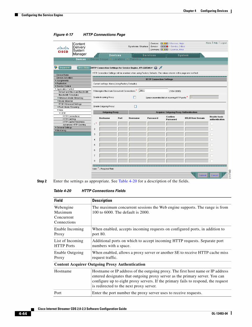
4-44Cisco Internet Streamer CDS 2.0-2.3 Software Configuration Guide
OL-13493-04
Chapter 4 Configuring DevicesConfiguring the Service Engine
Figure 4-17 HTTP Connections Page
Step 2 Enter the settings as appropriate. See Table 4-20 for a description of the fields.
Table 4-20 HTTP Connections Fields
Field Description
Webengine Maximum Concurrent Connections
The maximum concurrent sessions the Web engine supports. The range is from 100 to 6000. The default is 2000.
Enable Incoming Proxy
When enabled, accepts incoming requests on configured ports, in addition to port 80.
List of Incoming HTTP Ports
Additional ports on which to accept incoming HTTP requests. Separate port numbers with a space.
Enable Outgoing Proxy
When enabled, allows a proxy server or another SE to receive HTTP cache miss request traffic.
Content Acquirer Outgoing Proxy Authentication
Hostname Hostname or IP address of the outgoing proxy. The first host name or IP address entered designates that outgoing proxy server as the primary server. You can configure up to eight proxy servers. If the primary fails to respond, the request is redirected to the next proxy server.
Port Enter the port number the proxy server uses to receive requests.

4-45Cisco Internet Streamer CDS 2.0-2.3 Software Configuration Guide
OL-13493-04
Chapter 4 Configuring DevicesConfiguring the Service Engine
Step 3 Click Submit to save the settings.
Configuring Web Engine HTTP Caching
To configure web engine HTTP caching, do the following:
Step 1 Choose Devices > Devices > Application Control > Web > HTTP > HTTP Caching. The HTTP Caching page is displayed (Figure 4-18).
Figure 4-18 HTTP Caching Page
Step 2 In the Max Object Size field, enter the maximum content object size (in megabytes) that the SE will cache. The range is from 0 to 2047. Zero (0) means no limit.
Username If authentication is required, enter a username. This username is used for both NTLM and basic authentication.
Password Enter the password for the user.
Confirm Password Re-enter the password for the user.
NTLM User Domain
The NTLM server domain name used to authenticate the user.
Disable Basic Authentication
If checked, basic authentication will not occur as a fallback to an NTLM authentication failure.
Table 4-20 HTTP Connections Fields (continued)
Field Description

4-46Cisco Internet Streamer CDS 2.0-2.3 Software Configuration Guide
OL-13493-04
Chapter 4 Configuring DevicesConfiguring the Service Engine
Step 3 Click Submit to save the settings.
Configuring Web Engine HTTP Cache Freshness
To configure the web engine HTTP cache freshness, do the following:
Step 1 Choose Devices > Devices > Application Control > Web > HTTP > HTTP Cache Freshness. The HTTP Cache Freshness page is displayed (Figure 4-19).
Figure 4-19 HTTP Cache Freshness Page
Step 2 Enter the settings as appropriate. See Table 4-21 for a description of the fields.
Table 4-21 HTTP Cache Freshness Fields
Field Description
Enable When checked, HTTP cache freshness is enabled.
Object Age Multiplier The age multiplier value (as a percentage) enables the SE to guess the life of an object by multiplying the time since the object was last modified by a percentage to obtain an approximate expiration date. After this date, the object is considered stale, and subsequent results cause a fresh retrieval by the SE. The range is from 0 to 100. The default value is 30.
Max TTL Scale The scale (seconds, hours, minutes, or days) to use for the Max Object TTL.
The time-to-live (TTL) sets a ceiling on estimated expiration dates. If an object has an explicit expiration date, this takes precedence over the configured TTL.

4-47Cisco Internet Streamer CDS 2.0-2.3 Software Configuration Guide
OL-13493-04
Chapter 4 Configuring DevicesConfiguring the Service Engine
Step 3 Click Submit to save the settings.
Configuring Web Engine Advanced HTTP Caching
To configure web engine advanced HTTP cache settings, do the following:
Step 1 Choose Devices > Devices > Application Control > Web > HTTP > Advanced HTTP Caching. The Advanced HTTP Caching page is displayed (Figure 4-20).
Figure 4-20 Advanced HTTP Caching Page
Step 2 Enter the settings as appropriate. See Table 4-22 for a description of the fields.
Max Object TTL The minimum time-to-live (TTL) for objects in cache. The valid ranges are as follows:
1 to 1825 days1 to 43800 hours1 to 2628000 minutes1 to 157680000 seconds
Minimum TTL The minimum time-to-live (in minutes) for objects in the cache. The range is from 0 to 86400. The default value is 30.
Enable Re-evaluate Request All
When enabled, all requests are re-evaluated, whether for objects or directory listings.
Table 4-21 HTTP Cache Freshness Fields (continued)
Field Description

4-48Cisco Internet Streamer CDS 2.0-2.3 Software Configuration Guide
OL-13493-04
Chapter 4 Configuring DevicesConfiguring the Service Engine
Step 3 Click Submit to save the settings.
General SettingsThe General Settings pages provide settings for access control of the device, maintenance, network connectivity, and monitoring. The configuring of general settings consists of the following procedures:
• Configuring Content Management
• Login Access Control
• Authentication
• Scheduling Database Maintenance
• Setting Storage Handling
• Network Settings
• Configuring Notification and Tracking
• Configuring Troubleshooting
• Configuring Service Router Settings
Configuring Content Management
Note This is a Release 2.1 feature.
To configure the maximum number of entries for cache content, do the following:
Table 4-22 Advanced HTTP Caching Fields
Field Description
Enable Cache Cookies When enabled, the Web engine caches requests with a cookie header in the response.
Enable Cache Fill Range
When enabled, the complete content is cached when the range request for the same is given by the client. The range request starts with zero (0).
Enable Cache on Abort
When enabled, caching an object is continued even though the client has aborted the request.
Note The Abort Percentage Threshold field must be set for content to be cached when the client aborts.
Use Percentage Threshold
When enabled, caches an object if the percentage of the object already downloaded is greater than the percentage threshold value entered.
Abort Percentage Threshold
The percentage threshold at which the content is still cached even if the client aborts. The default value is 80 percent.
Note To ensure content is cached when the client aborts, set the Abort Percentage Threshold to a very small value.
4-49Cisco Internet Streamer CDS 2.0-2.3 Software Configuration Guide
OL-13493-04
Chapter 4 Configuring DevicesConfiguring the Service Engine
Step 1 Choose Devices > Devices > General Settings > Content Management. The Content Management page is displayed.
Step 2 In the Max Cache Content Entries field, enter the value for the maximum entries of cached content allowed. The range is from 1 to 5000000. The default is 3000000.
Step 3 Click Submit to save the settings.
Login Access Control
Login authentication and authorization are used to control user access and configuration rights to CDSMs, SEs, and SRs. Login authentication is the process by which the devices verify whether the person who is attempting to log in to the device has a valid username and password. The person logging in must have a user account registered with the device. User account information serves to authorize the user for login and configuration privileges. The user account information is stored in an authentication, authorization, and accounting (AAA) database, and the devices must be configured to access the particular authentication server (or servers) where the AAA database is kept.
In a CDS network, user accounts can be created for access to the CDSM and, independently, for access to the SEs and SRs that are registered to the CDSM. For user accounts that access the CDSM, see “Configuring AAA” section on page 6-1.
Login Authentication
Login authentication provides the configuration for independent logins; in other words, login access to the device only.
Note If you plan to use a RADIUS server for authentication, you must configure RADIUS server settings before you configure and submit these settings. See the “Configuring a RADlUS Server” section on page 4-54 for RADIUS server settings information.
When the primary login server and the primary configuration server are set to local, usernames and passwords are local to each device. Local authentication and authorization uses locally configured login and passwords to authenticate login attempts.
By default, local login authentication is enabled. You can disable local login authentication only after enabling one or more of the other login authentication servers. However, when local login authentication is disabled, if you disable all other login authentication methods, local login authentication is re-enabled automatically.
Caution Make sure that RADIUS authentication is configured and operating correctly before disabling local authentication and authorization. If you disable local authentication and RADIUS is not configured correctly, or if the RADIUS server is not online, you may be unable to log in to the device.
To configure the login authentication and configuration authorization schemes for the SE, do the following:
Step 1 Choose Devices > Devices > General Settings > Login Access Control > Login Authentication. The Login Authentication page is displayed.

4-50Cisco Internet Streamer CDS 2.0-2.3 Software Configuration Guide
OL-13493-04
Chapter 4 Configuring DevicesConfiguring the Service Engine
Step 2 Enter the settings as appropriate. See Table 4-23 for a description of the fields.
Step 3 Click Submit to save the settings.
Configuring SSH
Secure Shell (SSH) consists of a server and a client program. Like Telnet, you can use the client program to remotely log in to a machine that is running the SSH server. However, unlike Telnet, messages transported between the client and the server are encrypted. The functionality of SSH includes user authentication, message encryption, and message authentication.
The SSH page allows you to specify the key length and login grace time.
To enable the SSH daemon, follow these steps:
Step 1 Choose Devices > Devices > General Settings > Login Access Control > SSH. The SSH page is displayed.
Step 2 Check Enable to enable the SSH feature. SSH enables login access to the SE through a secure and encrypted channel.
Step 3 In the Length of Key field, specify the number of bits needed to create an SSH key. The default is 2048.
Step 4 In the Login Grace Time field, specify the number of seconds the server waits for the user to successfully log in before it ends the connection. The authentication procedure must be completed within this time limit. The default is 300 seconds.
Table 4-23 Login Authentication Fields
Field Description
Enable Failover Server Unreachable
If Enable Failover Server Unreachable is enabled, the device fails over to the secondary server only if the primary server is unreachable. In any other case, for example, the authentication fails in the RADIUS server, the local database is not contacted for authentication. Conversely, if the Enable Failover Server Unreachable option is disabled, the device contacts the secondary server, regardless of the reason the authentication failed with the primary server.
Authentication Login Servers
When enabled, authentication login servers are used to authenticate user logins.
Primary Login Server Choose either local or RADIUS.
Secondary Login Server
Choose either local or RADIUS.
Authentication Config Server
When enabled, authentication configuration servers are used to authenticate user privileges.
Primary Config Server Choose either local or RADIUS.
Secondary Config Server
Choose either local or RADIUS.

4-51Cisco Internet Streamer CDS 2.0-2.3 Software Configuration Guide
OL-13493-04
Chapter 4 Configuring DevicesConfiguring the Service Engine
Note When changing the Login Grace Time, you need to first uncheck the Enable check box and click Submit. Enter the new Login Grace Time, check Enable, and click Submit.
Step 5 Select the SSH version.
a. To allow clients to connect using SSH protocol version 1, check the Enable SSHv1 check box.
b. To allow clients to connect using SSH protocol version 2, check the Enable SSHv2 check box.
Note You can enable both SSHv1 and SSHv2, or you can enable one version and not the other. You cannot disable both versions of SSH unless you disable the SSH feature by unchecking the Enable check box.
Step 6 Click Submit to save the settings.
Enabling Telnet
To enable the Telnet service, do the following:
Step 1 Choose Devices > Devices > General Settings > Login Access Control > Telnet. The Telnet page is displayed.
Step 2 Check Telnet Enable to enable the terminal emulation protocol for remote terminal connections.
Step 3 Click Submit to save the settings.
Setting the Message of the Day
The Message of the Day (MOTD) feature enables you to provide information bits to the users when they log in to an SE. There are three types of messages that you can set up:
• MOTD banner
• EXEC process creation banner
• Login banner
To configure the Message of the Day settings, do the following:
Step 1 Choose Devices > Devices > General Settings > Login Access Control > Message of the Day. The MOTD page is displayed.
Step 2 Check Enable to enable the MOTD settings. The Message of the Day (MOTD) banner, EXEC process creation banner, and Login banner fields become enabled.
Step 3 In the Message of the Day (MOTD) Banner field, enter a string that you want to display as the MOTD banner when a user attempts to log in to the SE.

4-52Cisco Internet Streamer CDS 2.0-2.3 Software Configuration Guide
OL-13493-04
Chapter 4 Configuring DevicesConfiguring the Service Engine
Note In the Message of the Day (MOTD) Banner, EXEC Process Creation Banner, and Login Banner fields, you can enter a maximum of 980 characters. A new line character (or Enter) is counted as two characters, as it is interpreted as \n by the system. You cannot use special characters such as `, % ,^ , and " in the MOTD text.
Step 4 In the EXEC Process Creation Banner field, enter a string to be displayed as the EXEC process creation banner when a user enters into the EXEC shell of the SE.
Step 5 In the Login Banner field, enter a string to be displayed after the MOTD banner, when a user attempts to log in to the SE.
Step 6 Click Submit to save the settings.
Changing the CLI Session Time
To change the CLI session time, do the following:
Step 1 Choose Devices > Devices > General Settings > Login Access Control > CLI Session Time. The CLI Session Time page is displayed.
Step 2 In the CLI Session Time field, enter the time (in minutes) that the SE waits for a response before ending the session.
Step 3 Click Submit to save the settings.
Changing Users—Admin Password
Every device (CDSM, SE, and SR) has a built-in user account. The username is admin and the default password is default. This account allows access to all services and entities in the CDS. Any user that can access the Admin Password page in the CDSM, can configure a new password for the administrator user account on individual SEs and SRs.
To change the Admin password, do the following:
Step 1 Choose Devices > Devices > General Settings > Login Access Control > Users > Admin Password. The Admin Password page is displayed.
Step 2 In the Password field, enter a new password.
Step 3 In the Confirm Password field, reenter the password.
Step 4 Click Submit to save the settings.
Creating, Editing, and Deleting Users—Usernames
You can create, edit, and delete user accounts for login access to individual devices or device groups. A privilege profile must be assigned to each new user account. The Usernames page uses privilege profiles to determine which tasks a user can perform and the level of access provided. Users with administrative privileges can add, delete, or modify user accounts through the CDSM or the device CLI.

4-53Cisco Internet Streamer CDS 2.0-2.3 Software Configuration Guide
OL-13493-04
Chapter 4 Configuring DevicesConfiguring the Service Engine
To create, edit, or delete a user account, do the following:
Step 1 Choose Devices > Devices > General Settings > Login Access Control > Users > Usernames. The User Table page is displayed.
Step 2 Aggregate Settings is set to Yes by default. If this SE belongs to a device group, and the settings have not been configured using the device group, you can enter the settings and they will apply to the device group as well.
If the settings are previously configured through the device group, the current configuration is displayed for view only. New settings must be configured through the associated device group.
If you want to configure settings for this SE only, and override the device group settings on this SE, set Aggregate Settings to No.
If you remove all device group settings, all device settings displayed with Aggregate Settings enabled are removed as well.
Note The last configuration submitted for the device, whether it is the device group configuration or the individual device configuration, is the configuration the device uses.
Step 3 Click the Create New icon in the task bar. The Local User page is displayed.
To edit a local user, click the Edit icon next to the name you want to edit.
Step 4 Enter the settings as appropriate. See Table 4-24 for a description of the fields.
Step 5 Click Submit to save the settings.
To delete a user, click the Trash icon in the task bar.
Authentication
User authentication and authorization (configuration rights) data can be maintained in any combination of these two databases:
• Local database (located on the SE)
• RADIUS server (external database)
Table 4-24 Local User Fields
Field Description
Username Name of user.
Password User password.
Confirm Password Re-enter user password.
Privilege There are two types of predefined privilege profiles:
• Normal user—User has read access and can see some of the SE, SR, or CDSM settings.
• Superuser—User has administrative privileges such as creating new users and modifying the SE, SR, or CDSM settings.
4-54Cisco Internet Streamer CDS 2.0-2.3 Software Configuration Guide
OL-13493-04
Chapter 4 Configuring DevicesConfiguring the Service Engine
The Login Authentication page allows you to choose an external access server or the internal (local) device-based authentication, authorization, and accounting (AAA) system for user access management. You can choose one method or a combination of the two methods. The default is to use the local database for authentication.
Configuring a RADlUS Server
Note The CDSM does not cache user authentication information. Therefore, the user is reauthenticated against the RADIUS server for every request. To prevent performance degradation caused by many authentication requests, install the CDSM in the same location as the RADIUS server, or as close as possible to it, to ensure that authentication requests can occur as quickly as possible.
To configure the RADIUS server settings, do the following:
Step 1 Choose Devices > Devices > General Settings > Authentication > RADIUS Server. The RADIUS Server Settings page is displayed.
Step 2 Enter the settings as appropriate. See Table 4-25 for a description of the fields.
Step 3 Click Submit to save the settings.
Table 4-25 RADIUS Server Settings Fields
Field Description
Enable RADIUS Servers
Enables RADIUS authentication.
Time to wait Number of seconds to wait for a response before timing out on a connection to a RADIUS server. The range is from 1 to 20. The default is 5.
Number of retransmits
Number of attempts allowed to connect to a RADIUS server. The default is 2.
Enable redirect Redirects an authentication response to a different authentication server if an authentication request using the RADIUS server fails.
Redirect Message [1-3]
Message sent to the user if redirection occurs.
Note If the redirect message has a space, it must be in quotes (" ").
Location [1-3] Sets an HTML page location. This is the URL destination of the redirect message that is sent when authentication fails.
Shared Encryption Key
Encryption key shared with the RADIUS server.
Server Name [1-5] IP address or hostname of the RADIUS server.
Server Port [1-5] Port number on which the RADIUS server is listening.

4-55Cisco Internet Streamer CDS 2.0-2.3 Software Configuration Guide
OL-13493-04
Chapter 4 Configuring DevicesConfiguring the Service Engine
Configuring an Access Control List
To configure an access control list (ACL) for group authorization, do the following:
Step 1 Choose Devices > Devices > General Settings > Authentication > Access Control List > Configure Access Control List. The Access Control List Table page is displayed.
Step 2 Click the Create New icon in the task bar. The Configure Access Control List page is displayed.
To edit a group, click the Edit icon next to the name you want to edit.
Step 3 Enter the settings as appropriate. See Table 4-26 for a description of the fields.
Step 4 Click Submit to save the settings.
To delete a group, click the Trash icon in the task bar.
Step 5 From the left-panel menu, choose Enable Access Control List. The Enable Access Control List page is displayed.
Step 6 Check the Enable Access Control List check box and click Submit.
To move a group up or down in the Access Control List table, click the Up arrow or Down arrow in the Move column.
The ACL can be applied from the SE or from a device group. The source of the currently applied settings is shown in the Access Control List Table page.
Scheduling Database Maintenance
The database maintenance runs at the scheduled time only when the following three conditions are satisfied:
• The last vacuum process happened more than 30 minutes in the past.
• The percent increase in disk space usage is greater than 10 percent.
• The available free disk space is greater than 10 percent of the total disk space.
If any of these conditions are not satisfied, the database maintenance does not run at the scheduled time.
To schedule a database cleaning or reindexing, do the following:
Step 1 Choose Devices > Devices > General Settings > Database Maintenance. The Database Maintenance Settings page is displayed.
Table 4-26 Access Control List Fields
Field Description
Action Whether to permit or deny access for this group.
Group Name If this action is for all groups, choose Any Group Name.
If this action is for a specific group, choose Enter Group Name and enter the group name in the field.
Change Position To change the order of this group in the access control list, which is displayed in the Access Control List Table page, click Change Position.
4-56Cisco Internet Streamer CDS 2.0-2.3 Software Configuration Guide
OL-13493-04
Chapter 4 Configuring DevicesConfiguring the Service Engine
Step 2 Enter the settings as appropriate. See Table 4-27 for a description of the fields.
Step 3 Click Submit to save the settings.
Setting Storage Handling
The Storage option offers disk error-handling settings.
Enabling Disk Error Handling
The Disk Error Handling page allows you to configure how disk errors are handled, and to define a disk device error-handling threshold.
If a bad disk drive is a critical disk drive, and the automatic reload feature (disk error-handling reload command) is enabled, the disk drive is marked as “bad” and the SE is automatically reloaded. After the SE is reloaded, a syslog message and an SNMP trap are generated.
The disk error-handling threshold option determines how many disk errors can be detected before the disk drive is automatically marked “bad.” By default, this threshold is set to 10.
To configure a disk error-handling method, do the following:
Step 1 Choose Devices > Devices > General Settings > Storage > Disk Error Handling. The Disk Error Handling Settings page is displayed.
Step 2 Check the Enable check box.
Step 3 Check the Enable Disk Error Handling Reload check box if you want the device to reload the disk when a disk with a system file system (sysfs) has problems.
Step 4 Check the Enable Disk Error Handling Remap check box if you want to set the disks to attempt to remap disk errors automatically. This option is enabled by default.
Table 4-27 Database Maintenance Settings Fields
Field Description
Full Database Maintenance Settings
Enable When enabled, a full database maintenance routine is performed on the SE.
Every Day
Sun-Sat
The days of the week when the maintenance is performed
When Every Day is enabled, all days of the week are also enabled.
At (time) Time of day the maintenance is performed. Time is entered in 24-hour format as hh:mm. The default is 04:00.
Regular Database Maintenance Settings
Enable When enabled, a re-indexing routine is performed on the SE.
Every Day
Sun-Sat
The days of the week when the maintenance is performed.
When Every Day is enabled, all days of the week are also enabled.
At (time) Time of day the maintenance is performed. Time is entered in 24-hour format as hh:mm. The default is 02:00.

4-57Cisco Internet Streamer CDS 2.0-2.3 Software Configuration Guide
OL-13493-04
Chapter 4 Configuring DevicesConfiguring the Service Engine
Step 5 Check the Enable Disk Error Handling Threshold check box if you want to set the number of disk errors allowed before the disk is marked as bad, and enter a number (0 to 100) in the Threshold field. The default threshold is 10.
Step 6 Click Submit to save the settings.
Network Settings
The Network pages provide settings for network connectivity. Configuring network settings consist of the following procedures:
• Enabling FTP Services
• Enabling DNS
• Enabling RCP
• Configuring NTP
• Setting the Time Zone
• Viewing Network Interfaces
• Configuring External IP Addresses
• Configuring Port Channel and Load Balancing Settings
• Configuring TCP Settings
• Configuring IP General Settings
• Configuring IP ACL
• Configuring Static IP Routes
Enabling FTP Services
To enable FTP services to listen for connection requests, do the following:
Step 1 Choose Devices > Devices > General Settings > Network > FTP. The FTP Settings page is displayed.
Step 2 Check the Enable FTP Services check box.
Step 3 Click Submit to save the settings.
Enabling DNS
To configure Domain Name System (DNS) servers, do the following:
Step 1 Choose Devices > Devices > General Settings > Network > DNS. The DNS Settings page is displayed.
Step 2 Enter the settings as appropriate. See Table 4-28 for a description of the fields.
4-58Cisco Internet Streamer CDS 2.0-2.3 Software Configuration Guide
OL-13493-04
Chapter 4 Configuring DevicesConfiguring the Service Engine
Step 3 Click Submit to save the settings.
Enabling RCP
Remote Copy Protocol (RCP) lets you download, upload, and copy configuration files between remote hosts and a switch. Unlike TFTP, which uses User Datagram Protocol (UDP), a connectionless protocol, RCP uses TCP, which is connection oriented. This service listens for requests on TCP port 514.
To enable RCP services, do the following:
Step 1 Choose Devices > Devices > General Settings > Network > RCP. The RCP page is displayed.
Step 2 Check the RCP Enable check box to have the RCP services listen for RCP requests.
Step 3 Click Submit to save the settings.
Configuring NTP
To configure the SE to synchronize its clock with an NTP server, do the following:
Step 1 Choose Devices > Devices > General Settings > Network > NTP. The NTP page is displayed.
Step 2 Check Enable to enable NTP.
Step 3 In the NTP Server field, enter the IP address or host name of up to four NTP servers. Use a space to separate the entries.
Step 4 Click Submit to save the settings.
Table 4-28 DNS Settings Fields
Field Description
Enable Enables Domain Name System (DNS) on the SE.
List of DNS Servers Space-delimited list of IP addresses for up to eight name servers for name and address resolution.
Domain Names A space-delimited list of up to three default domain names. A default domain name allows the system to resolve any unqualified hostnames. Any IP hostname that does not contain a domain name will have the configured domain name appended to it. This appended name is resolved by the DNS server and then added to the host table. A DNS server must be configured on the system for hostname resolution to work correctly. To do this, use the List of DNS Servers field.

4-59Cisco Internet Streamer CDS 2.0-2.3 Software Configuration Guide
OL-13493-04
Chapter 4 Configuring DevicesConfiguring the Service Engine
Setting the Time Zone
If you have an outside source on your network that provides time services, such as an NTP server, you do not need to set the system clock manually. When manually setting the clock, enter the local time. The SE calculates Coordinated Universal Time (UTC) based on the time zone set.
Note Two clocks exist in the system: the software clock and the hardware clock. The software uses the software clock. The hardware clock is used only at startup to initialize the software clock.
Caution We highly recommend that you use NTP servers to synchronize the devices in your CDS network.
To manually configure the time zone, do the following:
Step 1 Choose Devices > Devices > General Settings > Network > Time Zone. The Time Zone page is displayed with the default settings of UTC (offset = 0) and no daylight savings time configured.
Step 2 To configure a standard time zone, do the following:
a. Click the Standard Time Zone radio button.
The standard convention for time zones uses a Location/Area format in which Location is a continent or a geographic region of the world and Area is a time zone region within that location. For a list of standard time zones that can be configured and their UTC offsets, see Table 4-29 on page 4-60.
b. From the Standard Time Zone drop-down list, choose a location for the time zone. The page refreshes, displaying all area time zones for the chosen location in the second drop-down list.
c. Choose an area for the time zone.
The UTC offset (hours and minutes ahead or behind UTC) for the corresponding time zone is displayed. During summer time savings, the offset may differ and is displayed accordingly.
Note Some of the standard time zones (mostly time zones within the United States) have daylight savings time zones configured automatically.
Step 3 To configure a customized time zone, do the following:
a. Click the Customized Time Zone radio button.
b. In the Customized Time Zone field, enter a name to for the time zone. The time zone entry is case sensitive and can contain up to 40 characters. Spaces are not allowed. If you specify any of the standard time zone names, an error message is displayed when you click Submit.
c. For UTC offset, choose + or – from the UTC Offset drop-down list to indicate whether the configured time zone is ahead or behind UTC. Also, choose the number of hours (0 to 23) and minutes (0 to 59) offset from UTC for the customized time zone. The range for the UTC offset is from –23:59 to 23:59, and the default is 0:0.
Step 4 To configure customized summer time savings, do the following:
Note Customized summer time can be specified for both standard and customized time zones.
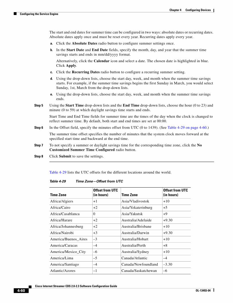
4-60Cisco Internet Streamer CDS 2.0-2.3 Software Configuration Guide
OL-13493-04
Chapter 4 Configuring DevicesConfiguring the Service Engine
The start and end dates for summer time can be configured in two ways: absolute dates or recurring dates. Absolute dates apply once and must be reset every year. Recurring dates apply every year.
a. Click the Absolute Dates radio button to configure summer settings once.
b. In the Start Date and End Date fields, specify the month, day, and year that the summer time savings starts and ends in mm/dd/yyyy format.
Alternatively, click the Calendar icon and select a date. The chosen date is highlighted in blue. Click Apply.
c. Click the Recurring Dates radio button to configure a recurring summer setting.
d. Using the drop-down lists, choose the start day, week, and month when the summer time savings starts. For example, if the summer time savings begins the first Sunday in March, you would select Sunday, 1st, March from the drop-down lists.
e. Using the drop-down lists, choose the start day, week, and month when the summer time savings ends.
Step 5 Using the Start Time drop-down lists and the End Time drop-down lists, choose the hour (0 to 23) and minute (0 to 59) at which daylight savings time starts and ends.
Start Time and End Time fields for summer time are the times of the day when the clock is changed to reflect summer time. By default, both start and end times are set at 00:00.
Step 6 In the Offset field, specify the minutes offset from UTC (0 to 1439). (See Table 4-29 on page 4-60.)
The summer time offset specifies the number of minutes that the system clock moves forward at the specified start time and backward at the end time.
Step 7 To not specify a summer or daylight savings time for the corresponding time zone, click the No Customized Summer Time Configured radio button.
Step 8 Click Submit to save the settings.
Table 4-29 lists the UTC offsets for the different locations around the world.
Table 4-29 Time Zone—Offset from UTC
Time ZoneOffset from UTC (in hours) Time Zone
Offset from UTC (in hours)
Africa/Algiers +1 Asia/Vladivostok +10
Africa/Cairo +2 Asia/Yekaterinburg +5
Africa/Casablanca 0 Asia/Yakutsk +9
Africa/Harare +2 Australia/Adelaide +9.30
Africa/Johannesburg +2 Australia/Brisbane +10
Africa/Nairobi +3 Australia/Darwin +9.30
America/Buenos_Aires –3 Australia/Hobart +10
America/Caracas –4 Australia/Perth +8
America/Mexico_City –6 Australia/Sydney +10
America/Lima –5 Canada/Atlantic –4
America/Santiago –4 Canada/Newfoundland –3.30
Atlantic/Azores –1 Canada/Saskatchewan –6

4-61Cisco Internet Streamer CDS 2.0-2.3 Software Configuration Guide
OL-13493-04
Chapter 4 Configuring DevicesConfiguring the Service Engine
The offset time (number of hours ahead or behind UTC) as displayed in the table is in effect during winter time. During summer time or daylight savings time, the offset may be different from the values in the table and is calculated and displayed accordingly by the system clock.
Viewing Network Interfaces
The Network Interfaces page is informational only. To view this information, choose Devices > Devices > General Settings > Network > Network Interfaces. Information about the network interfaces configured for the SE is displayed.
Configuring External IP Addresses
The External IP page allows you to configure up to eight Network Address Translation (NAT) IP addresses. This allows a router to translate up to eight internal addresses to registered unique addresses and translate external registered addresses to addresses that are unique to the private network.
To configure NAT IP addresses, do the following:
Atlantic/Cape_Verde –1 Europe/Athens +2
Asia/Almaty +6 Europe/Berlin +1
Asia/Baghdad +3 Europe/Bucharest +2
Asia/Baku +4 Europe/Helsinki +2
Asia/Bangkok +7 Europe/London 0
Asia/Colombo +6 Europe/Moscow +3
Asia/Dacca +6 Europe/Paris +1
Asia/Hong_Kong +8 Europe/Prague +1
Asia/Irkutsk +8 Europe/Warsaw +1
Asia/Jerusalem +2 Japan +9
Asia/Kabul +4.30 Pacific/Auckland +12
Asia/Karachi +5 Pacific/Fiji +12
Asia/Katmandu +5.45 Pacific/Guam +10
Asia/Krasnoyarsk +7 Pacific/Kwajalein –12
Asia/Magadan +11 Pacific/Samoa –11
Asia/Muscat +4 US/Alaska –9
Asia/New Delhi +5.30 US/Central –6
Asia/Rangoon +6.30 US/Eastern –5
Asia/Riyadh +3 US/East–Indiana –5
Asia/Seoul +9 US/Hawaii –10
Asia/Singapore +8 US/Mountain –7
Asia/Taipei +8 US/Pacific –8
Asia/Tehran +3.30
Table 4-29 Time Zone—Offset from UTC (continued)
Time ZoneOffset from UTC (in hours) Time Zone
Offset from UTC (in hours)

4-62Cisco Internet Streamer CDS 2.0-2.3 Software Configuration Guide
OL-13493-04
Chapter 4 Configuring DevicesConfiguring the Service Engine
Step 1 Choose Devices > Devices > General Settings > Network > External IP. The External IP Settings page is displayed.
Step 2 Check the Enable check box.
Step 3 In the External IP Address fields (1–8), enter up to eight IP addresses.
Step 4 Click Submit to save the settings.
Configuring Port Channel and Load Balancing Settings
For information about configuring port channels using the CLI, see the “Redundant Dedicated Management Ports” section on page E-1.
To configure load balancing on port channels, do the following:
Step 1 Choose Devices > Devices > General Settings > Network > Port Channel Settings. The Port Channel Settings page is displayed.
Step 2 From the Load Balancing Method drop-down list, choose one of the following load balancing methods:
• dst-ip—Destination IP address
• dst-mac—Destination MAC address
• round robin—Each interface in the channel group
Round robin allows traffic to be distributed evenly among all interfaces in the channel group. The other balancing options give you the flexibility to choose specific interfaces (by IP address or MAC address) when sending an Ethernet frame.
Step 3 Click Submit to save the settings.
Configuring TCP Settings
Adjusting TCP parameters for better performance is often overlooked when configuring content caching. For data transactions and queries between client and servers, the size of windows and buffers is important, and fine-tuning the TCP stack parameters therefore becomes the key to maximizing cache performance.
Note Because of the complexities involved in TCP parameters, care is advised in tuning these parameters. In nearly all environments, the default TCP settings are adequate. Fine-tuning of TCP settings is for network administrators with adequate experience and full understanding of TCP operation details.
Caution The TCP memory limit settings allow you to control the amount of memory that can be used by the TCP subsystem send and receive buffers. The default values are device-dependent and have been chosen after extensive testing. They should not be changed under normal conditions. Increasing these values can result in the TCP subsystem using more memory, which might render the system unresponsive. Decreasing these values can result in increased response times and lower performance.
To configure TCP settings, do the following:

4-63Cisco Internet Streamer CDS 2.0-2.3 Software Configuration Guide
OL-13493-04
Chapter 4 Configuring DevicesConfiguring the Service Engine
Step 1 Choose Devices > Devices > General Settings > Network > TCP. The TCP Settings page is displayed.
Step 2 Enter the settings as appropriate. See Table 4-30 for a description of the fields.
Table 4-30 TCP Settings Fields
Field Description
TCP General Settings
Enable Explicit Congestion Notification
Enables reduction of delay and packet loss. For more information, see the “Explicit Congestion Notification” section on page 4-65.
Enable Type Of Service Enables Type of Service.
Congestion Window Size Congestion window size in segments. The default is 2. For more information, see the “Congestion Windows” section on page 4-65.
Retransmit Time Multiplier Factor used to modify the length of the retransmit timer by 1 to 3 times the base value determined by the TCP algorithm. For more information, see the “Retransmit Time Multiplier” section on page 4-65.
Note Modify this factor with caution. It can improve throughput when TCP is used over slow reliable connections but should never be changed within an unreliable packet delivery environment.
Initial Slow Start Threshold Threshold for slow start in segments. The default is 2. For more information, see the “TCP Slow Start” section on page 4-65.
Keepalive Probe Count Number of times the SE can retry a connection before it is considered unsuccessful. The default is 4.
Keepalive Probe Interval Length of time that the SE keeps an idle connection open. The default is 75 seconds.
Keepalive Timeout Length of time that the SE keeps a connection open before disconnecting. The default is 90 seconds.
TCP Server Settings
Enable Server Satellite Sets TCP server compliance to the RFC 1323 standard. For more information, see the “TCP-Over-Satellite Extensions” section on page 4-66.
Note If you enable a server satellite, the client satellite is automatically enabled.
Server Max Segment Size Maximum packet size sent to the server. The default is 1460 bytes.
Server Receive Buffer Size TCP receiving buffer size in kilobytes (1 to 512) for incoming TCP packets. The default is 32.
Server Read/Write Timeout Period after which the SE times out when attempting to read or write to the network. The default is 120 seconds.
Server Send Buffer TCP sending buffer size in kilobytes (1 to 512) for outgoing TCP packets. The default is 8.

4-64Cisco Internet Streamer CDS 2.0-2.3 Software Configuration Guide
OL-13493-04
Chapter 4 Configuring DevicesConfiguring the Service Engine
Table 4-31 describes the default values for each command parameter, which are based on the total amount of memory for the device.
TCP Client Settings
Enable Client Satellite Sets client TCP compliance to the RFC 1323 standard. For more information, see the “TCP-Over-Satellite Extensions” section on page 4-66.
Note If you enable a client satellite, the server satellite is automatically enabled.
Client Max Segment Size Maximum packet size sent to clients. The default is 1432 bytes.
Client Receive Buffer Size TCP receiving buffer size in kilobytes (8 to 512) for incoming TCP packets. The default is 8.
Client Read/Write Timeout Period after which the SE times out when attempting to read or write to the network. The default is 120 seconds.
Client Send Buffer Size TCP sending buffer size in kilobytes (8 to 512) for outgoing TCP packets. The default is 32.
TCP Memory Limit Settings
TCP Memory Limit Low Water Mark
The lower limit (MB) of memory pressure mode, below which TCP enters into normal memory allocation mode. The range is from 4 to 600.
Low—TCP does not regulate its memory allocation when the number of pages it has allocated globally is below this number.
TCP Memory Limit High Water Mark–Pressure
The upper limit (MB) of normal memory allocation mode, beyond which TCP enters into memory pressure mode. The range is from 5 to 610.
Pressure—When the amount of memory allocated by TCP exceeds this number of pages, TCP moderates its memory consumption. This memory pressure state is exited once the number of pages allocated falls below the low mark.
TCP Memory Limit High Water Mark–Absolute
The absolute limit (MB) on TCP memory usage. The range is from 6 to 620.
Absolute—The maximum number of pages, globally, that TCP will allocate.
Table 4-30 TCP Settings Fields (continued)
Field Description
Table 4-31 Default TCP Memory Limit Settings
Total System Memory Low Pressure Absolute
1 GB, 2 GB, or 4 GB 360 MB 380 MB 400 MB
512 MB 180 MB 190 MB 200 MB
256 MB 25 MB 28 MB 30 MB

4-65Cisco Internet Streamer CDS 2.0-2.3 Software Configuration Guide
OL-13493-04
Chapter 4 Configuring DevicesConfiguring the Service Engine
Step 3 Click Submit to save the settings.
Explicit Congestion Notification
The TCP Explicit Congestion Notification (ECN) feature allows an intermediate router to notify the end hosts of impending network congestion. It also provides enhanced support for TCP sessions associated with applications that are sensitive to delay or packet loss, including Telnet, web browsing, and transfer of audio and video data. The major issue with ECN is the need to change the operation of both the routers and the TCP software stacks to accommodate the operation of ECN.
Congestion Windows
The congestion window (cwnd) is a TCP state variable that limits the amount of data that a TCP sender can transmit onto the network before receiving an acknowledgment (ACK) from the receiving side of the TCP transmission. The TCP cwnd variable is implemented by the TCP congestion avoidance algorithm. The goal of the congestion avoidance algorithm is to continually modify the sending rate so that the sender automatically senses any increase or decrease in available network capacity during the entire data flow. When congestion occurs (manifested as packet loss), the sending rate is first lowered and then gradually increased as the sender continues to probe the network for additional capacity.
Retransmit Time Multiplier
The TCP sender uses a timer to measure the time that has elapsed between sending a data segment and receiving the corresponding ACK from the receiving side of the TCP transmission. When this retransmit timer expires, the sender (according to the RFC standards for TCP congestion control) must reduce its sending rate. However, because the sender is not reducing its sending rate in response to network congestion, the sender is not able to make any valid assumptions about the current state of the network. Therefore, in order to avoid congesting the network with an inappropriately large burst of data, the sender implements the slow start algorithm, which reduces the sending rate to one segment per transmission. (See the “TCP Slow Start” section on page 4-65.)
You can modify the sender’s retransmit timer by using the Retransmit Time Multiplier field in the CDSM or the tcp increase-xmit-timer-value global configuration command in the CLI. The retransmit time multiplier modifies the length of the retransmit timer by one to three times the base value, as determined by the TCP algorithm that is being used for congestion control.
When making adjustments to the retransmit timer, be aware that they affect performance and efficiency. If the retransmit timer is triggered too early, the sender pushes duplicate data onto the network unnecessarily; if the timer is triggered too slowly, the sender remains idle for too long, unnecessarily slowing data flow.
TCP Slow Start
Slow start is one of four congestion-control algorithms used by TCP. The slow start algorithm controls the amount of data being inserted into the network at the beginning of a TCP session, when the capacity of the network is not known.
For example, if a TCP session began by inserting a large amount of data into the network, much of the initial burst of data would probably be lost. Instead, TCP initially transmits a modest amount of data that has a high probability of successful transmission. TCP then probes the network by sending increasing amounts of data as long as the network does not show signs of congestion.
The slow start algorithm begins by sending packets at a rate that is determined by the congestion window, or cwnd variable. (See the “Congestion Windows” section on page 4-65.) The algorithm continues to increase the sending rate until it reaches the limit set by the slow start threshold (ssthresh) variable.
4-66Cisco Internet Streamer CDS 2.0-2.3 Software Configuration Guide
OL-13493-04
Chapter 4 Configuring DevicesConfiguring the Service Engine
(Initially, the value of the ssthresh variable is adjusted to the receiver’s maximum window size [RMSS]. However, when congestion occurs, the ssthresh variable is set to half the current value of the cwnd variable, marking the point of the onset of network congestion for future reference.)
The starting value of the cwnd variable is set to that of the sender maximum segment size (SMSS), which is the size of the largest segment that the sender can transmit. The sender sends a single data segment, and because the congestion window is equal to the size of one segment, the congestion window is now full. The sender then waits for the corresponding ACK from the receiving side of the transmission. When the ACK is received, the sender increases its congestion window size by increasing the value of the cwnd variable by the value of one SMSS. Now the sender can transmit two segments before the congestion window is again full and the sender is once more required to wait for the corresponding ACKs for these segments. The slow start algorithm continues to increase the value of the cwnd variable and therefore increase the size of the congestion window by one SMSS for every ACK received. If the value of the cwnd variable increases beyond the value of the ssthresh variable, then the TCP flow control algorithm changes from the slow start algorithm to the congestion-avoidance algorithm.
TCP-Over-Satellite Extensions
The SE has the ability to turn on TCP-over-satellite extensions (as documented in RFC 1323) to maximize performance and end-to-end throughput over satellite-type connections.
The large number of satellites available to network infrastructures has increased the amount of bandwidth available in the air. Taking advantage of these connections through satellite-type connections has created new challenges in the use of TCP transactions and acknowledgments:
• Latency—Round-trip times to satellites orbiting 24,000 miles above the earth are 550 milliseconds for a single satellite hop. Buffer size must be set to prevent low-throughput connections.
• Bit errors—Packet loss can occur in a land-based device-to-satellite connection in addition to the losses caused by regular network congestion.
• Asymmetric bandwidth—Return bandwidth from satellites can be narrower than receiving bandwidth, thereby affecting performance.
Use the fields provided under the TCP Server Settings and TCP Client Settings sections to set the TCP connection so that it complies with RFC 1323.
Configuring IP General Settings
The Path Maximum Transmission Unit (MTU) Discovery discovers the largest IP packet size allowable between the various links along the forwarding path and automatically sets the correct value for the packet size. By using the largest MTU the links will bear, the sending device can minimize the number of packets it must send.
Note The Path MTU Discovery is a process initiated by the sending device. If a server does not support IP Path MTU Discovery, the receiving device has no mechanism available to avoid fragmenting datagrams generated by the server.
To enable Path MTU Discovery, do the following:
Step 1 Choose Devices > Devices > General Settings > Network > IP General Settings. The IP General Settings page is displayed.
Step 2 Check Enable Path MTU Discovery.

4-67Cisco Internet Streamer CDS 2.0-2.3 Software Configuration Guide
OL-13493-04
Chapter 4 Configuring DevicesConfiguring the Service Engine
Step 3 Click Submit to save the settings.
Configuring IP ACL
Note This is a Release 2.1 feature.
Access control lists (ACLs) provide a means to filter packets by allowing a user to permit or deny IP packets from crossing specified interfaces. Packet filtering helps to control packet movement through the network. Such control can help limit network traffic and restrict network use by certain users or devices.
You can also apply ACLs to management services such as SNMP, SSH, HTTPS, Telnet, and FTP. ACLs can be used to control the traffic that these applications provide by restricting the type of traffic that the applications will handle.
In a managed CDS network environment, administrators need to be able to prevent unauthorized access to various devices and services. CDS supports standard and extended ACLs that allow administrators to restrict access to or through a CDS network device, such as the SE. Administrators can use ACLs to reduce the infiltration of hackers, worms, and viruses that can harm the network.
ACLs provide controls that allow various services to be tied to a particular interface. For example, the administrator can use IP ACLs to define a public interface on the Service Engine for content serving and a private interface for management services (for example, Telnet, SSH, SNMP, HTTPS, and software upgrades). A device attempting to access one of the services must be on a list of trusted devices before it is allowed access. The implementation of ACLs for incoming traffic on certain ports for a particular protocol type is similar to the ACL support for the Cisco Global Site Selector and Cisco routers.
To use ACLs, the system administrator must first configure ACLs and then apply them to specific services. The following are some examples of how IP ACLs can be used in various enterprise deployments:
• An application layer proxy firewall with a hardened outside interface has no ports exposed. (Hardened means that the interface carefully restricts which ports are available for access primarily for security reasons. Because the interface is outside, many types of attacks are possible.) The SE’s outside address is globally accessible from the Internet, while its inside address is private. The inside interface has an ACL to limit Telnet, SSH, and CDSM traffic.
• An SE is deployed anywhere within the enterprise. Like routers and switches, the administrator wants to limit Telnet, SSH, and CDSM access to the IT source subnets.
• An SE is deployed as a reverse proxy in an untrusted environment, and the administrator wishes to allow only port 80 inbound traffic on the outside interface and outbound connections on the back-end interface.
Note IP ACLs are defined for individual devices only. IP ACLs cannot be managed through device groups.
When you create an IP ACL, you should note the following constraints:
• IP ACL names must be unique within the device.
• IP ACL names must be limited to 30 characters and contain no spaces or special characters.
• The CDSM can manage up to 50 IP ACLs and a total of 500 conditions per device.

4-68Cisco Internet Streamer CDS 2.0-2.3 Software Configuration Guide
OL-13493-04
Chapter 4 Configuring DevicesConfiguring the Service Engine
• When the IP ACL name is numeric, numbers 1 through 99 denote standard IP ACLs and numbers 100 through 199 denote extended IP ACLs. IP ACL names that begin with a number cannot contain nonnumeric characters.
• Extended IP ACLs cannot be used with SNMP applications.
Creating a New IP ACL
To create a new IP ACL, do the following:
Step 1 Choose Devices > Devices > General Settings > Network > IP ACL. The IP ACL Table page is displayed.
Step 2 Click the Create New icon in the task bar. The IP ACL page is displayed.
To edit an ACL, click the Edit icon next to the name you want to edit.
Step 3 In the Name field, enter a name, observing the naming rules for IP ACLs.
Step 4 From the ACL Type drop-down list, choose an IP ACL type (Standard or Extended). The default is Standard.
Step 5 Click Submit. The page refreshes and the Modifying IP ACL page for a newly created IP ACL is displayed.
Note Clicking Submit at this point merely saves the IP ACL; IP ACLs without any conditions defined do not appear on the individual devices.
Adding Conditions to an IP ACL
To add conditions to an IP ACL, do the following:
Step 1 Choose Devices > Devices > General Settings > Network > IP ACL. The IP ACL Table page is displayed.
Step 2 Click the Edit icon next to the name of the IP ACL you want to add a condition to. The Modifying IP ACL page is displayed.
Step 3 Click the Create New icon in the task bar. The Condition page is displayed.
To edit a condition, click the Edit icon next to the name you want to edit.
Note The number of available fields for creating IP ACL conditions depends on the whether the IP ACL type is standard or extended.
Step 4 Enter values for the properties that are enabled for the type of IP ACL that you are creating.
• To create a standard IP ACL, go to Step 5.
• To create an extended IP ACL, go to Step 6.
Step 5 To set up conditions for a standard IP ACL, follow these steps:
a. From the Purpose drop-down list, choose a purpose (Permit or Deny).
b. In the Source IP field, enter the source IP address.
c. In the Source IP Wildcard field, enter a source IP wildcard address.

4-69Cisco Internet Streamer CDS 2.0-2.3 Software Configuration Guide
OL-13493-04
Chapter 4 Configuring DevicesConfiguring the Service Engine
d. Click Submit. The Modifying IP ACL page is displayed showing the new condition and its configuration.
e. To add another condition to the IP ACL, repeat the steps.
f. To reorder your list of conditions in the Modifying IP ACL page, use the Up arrow or Down arrow in the Order column, or click a column heading to sort by any configured parameter.
Note The order of the conditions listed becomes the order in which IP ACLs are applied to the device.
g. When you have finished adding conditions to the IP ACL, and you are satisfied with all your entries and the order in which the conditions are listed, click Submit in the Modifying IP ACL page to commit the IP ACL to the device database.
A green “Change submitted” indicator appears in the lower right corner of the Modifying IP ACL page to indicate that the IP ACL is being submitted to the device database.
Table 4-32 describes the fields in a standard IP ACL.
Step 6 To set up conditions for an extended IP ACL, follow these steps:
a. From the Purpose drop-down list, choose a purpose (Permit or Deny).
b. From the Extended Type drop-down list, choose Generic, TCP, UDP, or ICMP.
After you choose a type of extended IP ACL, various options become available depending on what type you choose.
c. Enter the settings as appropriate. See Table 4-33 for descriptions of the extended IP ACL fields.
d. Click Submit. The Modifying IP ACL page is displayed showing the new condition and its configuration.
e. To add another condition to the IP ACL, repeat the steps.
f. To reorder your list of conditions from the Modifying IP ACL page, use the Up arrow or Down arrow in the Order column, or click a column heading to sort by any configured parameter.
Note The order of the conditions listed becomes the order in which IP ACLs are applied to the device.
Table 4-32 Standard IP ACL Conditions
Field Default Value Description
Purpose1
1. Required field.
Permit Specifies whether a packet is to be passed (Permit) or dropped (Deny).
Source IP1 0.0.0.0 IP address of the network or host from which the packet is being sent, specified as a 32-bit quantity in 4-part dotted decimal format.
Source IP1 Wildcard
255.255.255.255 Wildcard bits to be applied to the source, specified as a 32-bit quantity in 4-part dotted decimal format. Place a 1 in the bit positions that you want to ignore and identify bits of interest with a 0.

4-70Cisco Internet Streamer CDS 2.0-2.3 Software Configuration Guide
OL-13493-04
Chapter 4 Configuring DevicesConfiguring the Service Engine
g. When you have finished adding conditions to the IP ACL, and you are satisfied with all your entries and the order in which the conditions are listed, click Submit in the Modifying IP ACL page to commit the IP ACL to the device database.
A green “Change submitted” indicator appears in the lower right corner of the Modifying IP ACL page to indicate that the IP ACL is being submitted to the device database.
Table 4-33 Extended IP ACL Conditions
Field Default Value Description Extended Type
Purpose1 Permit Specifies whether a packet is to be passed (Permit) or dropped (Deny).
Generic, TCP, UDP, ICMP
Protocol ip Internet protocol (gre, icmp, ip, tcp, or udp). To match any Internet protocol, use the ip keyword.
Generic
Established Unchecked (false) When checked, a match with the ACL condition occurs if the TCP datagram has the ACK or RST bits set, indicating an established connection. Initial TCP datagrams used to form a connection are not matched.
TCP
Source IP1 0.0.0.0 IP address of the network or host from which the packet is being sent, specified as a 32-bit quantity in 4-part dotted decimal format.
Generic, TCP, UDP, ICMP
Source IP Wildcard1 255.255.255.255 Wildcard bits to be applied to the source, specified as a 32-bit quantity in 4-part dotted decimal format. Place a 1 in the bit positions that you want to ignore and identify bits of interest with a 0.
Generic, TCP, UDP, ICMP
Source Port 1 0 Decimal number or name of a port. Valid port numbers are 0 to 65535. See Table 4-34 and Table 4-35 for port name descriptions and associated port numbers.
TCP, UDP
Valid TCP port names are as follows:
• domain
• exec
• ftp
• ftp-data
• https
• nfs
• rtsp
• ssh
• telnet
• www
Valid UDP port names are as follows:
• bootpc
• bootps
• domain
• netbios-dgm
• netbios-ns
• netbios-ss
• nfs
• ntp
• snmp
• snmptrap
Source Operator range Specifies how to compare the source ports against incoming packets. Choices are <, >, ==, !=, or range.
TCP, UDP
Source Port 2 65535 Decimal number or name of a port. See Source Port 1. TCP, UDP

4-71Cisco Internet Streamer CDS 2.0-2.3 Software Configuration Guide
OL-13493-04
Chapter 4 Configuring DevicesConfiguring the Service Engine
Destination IP 0.0.0.0 IP address of the network or host to which the packet is being sent, specified as a 32-bit quantity in 4-part dotted decimal format.
Generic, TCP, UDP, ICMP
Destination IP Wildcard
255.255.255.255 Wildcard bits to be applied to the source, specified as a 32-bit quantity in 4-part dotted decimal format. Place a 1 in the bit positions that you want to ignore and identify bits of interest with a 0.
Generic, TCP, UDP, ICMP
Destination Port 1 0 Decimal number or name of a port. Valid port numbers are 0 to 65535. See Table 4-34 and Table 4-35 for port name descriptions and associated port numbers.
TCP, UDP
Valid TCP port names are as follows:
• domain
• exec
• ftp
• ftp-data
• https
• nfs
• rtsp
• ssh
• telnet
• www
Valid UDP port names are as follows:
• bootpc
• bootps
• domain
• netbios-dgm
• netbios-ns
• netbios-ss
• nfs
• ntp
• snmp
• snmptrap
Destination Operator range Specifies how to compare the destination ports against incoming packets. Choices are <, >, ==, !=, or range.
TCP, UDP
Destination Port 2 65535 Decimal number or name of a port. See Destination Port 1. TCP, UDP
ICMP Param Type1 None Choices are None, Type/Code, or Msg.
• None—Disables the ICMP Type, Code, and Message fields.
• Type/Code—Allows ICMP messages to be filtered by ICMP message type and code. Also enables the ability to set an ICMP message code number.
• Msg—Allows a combination of type and code to be specified using a keyword. Activates the ICMP Message drop-down list. Disables the ICMP Type field.
ICMP
ICMP Message1 administratively-prohibited
Allows a combination of ICMP type and code to be specified using a keyword chosen from the drop-down list.
See Table 4-36 for descriptions of the ICMP messages.
ICMP
ICMP Type1 0 Number from 0 to 255. This field is enabled when you choose Type/Code.
ICMP
Table 4-33 Extended IP ACL Conditions (continued)
Field Default Value Description Extended Type

4-72Cisco Internet Streamer CDS 2.0-2.3 Software Configuration Guide
OL-13493-04
Chapter 4 Configuring DevicesConfiguring the Service Engine
Table 4-34 lists the UDP keywords that you can use with extended access control lists.
Table 4-35 lists the TCP keywords that you can use with extended access control lists.
Table 4-36 lists the keywords that you can use to match specific ICMP message types and codes.
Use ICMP Code1 Unchecked When checked, enables the ICMP Code field. ICMP
ICMP Code1 0 Number from 0 to 255. Message code option that allows ICMP messages of a particular type to be further filtered by an ICMP message code.
ICMP
1. Required field.
Table 4-33 Extended IP ACL Conditions (continued)
Field Default Value Description Extended Type
Table 4-34 UDP Keywords and Port Numbers
Port Name Description UDP Port Number
bootpc Bootstrap Protocol (BOOTP) client service 68
bootps Bootstrap Protocol (BOOTP) server service 67
domain Domain Name System (DNS) service 53
netbios-dgm NetBIOS datagram service 138
netbios-ns NetBIOS name resolution service 137
netbios-ss NetBIOS session service 139
nfs Network File System service 2049
ntp Network Time Protocol settings 123
snmp Simple Network Management Protocol service 161
snmptrap SNMP traps 162
Table 4-35 TCP Keywords and Port Numbers
Port Name Description TCP Port Number
domain Domain Name System service 53
exec Remote process execution 512
ftp File Transfer Protocol service 21
ftp-data FTP data connections (used infrequently) 20
https Secure HTTP service 443
nfs Network File System service applications 2049
rtsp Real-Time Streaming Protocol applications 554
ssh Secure Shell login 22
telnet Remote login using Telnet 23
www World Wide Web (HTTP) service 80

4-73Cisco Internet Streamer CDS 2.0-2.3 Software Configuration Guide
OL-13493-04
Chapter 4 Configuring DevicesConfiguring the Service Engine
Table 4-36 Keywords for ICMP Message Type and Code
Message Description
administratively-prohibited Messages that are administratively prohibited from being allowed access.
alternate-address Messages that specify alternate IP addresses.
conversion-error Messages that denote a datagram conversion error.
dod-host-prohibited Messages that signify a Department of Defense (DoD) protocol Internet host denial.
dod-net-prohibited Messages that specify a DoD protocol network denial.
echo Messages that are used to send echo packets to test basic network connectivity.
echo-reply Messages that are used to send echo reply packets.
general-parameter-problem Messages that report general parameter problems.
host-isolated Messages that indicate that the host is isolated.
host-precedence-unreachable Messages that have been received with the protocol field of the IP header set to 1 (ICMP) and the type field in the ICMP header set to 3 (Host Unreachable). This is the most common response. Large numbers of this datagram type on the network are indicative of network difficulties or may be indicative of hostile actions.
host-redirect Messages that specify redirection to a host.
host-tos-redirect Messages that specify redirection to a host for type of service-based (ToS) routing.
host-tos-unreachable Messages that denote that the host is unreachable for ToS-based routing.
host-unknown Messages that specify that the host or source is unknown.
host-unreachable Messages that specify that the host is unreachable.
information-reply Messages that contain domain name replies.
information-request Messages that contain domain name requests.
mask-reply Messages that contain subnet mask replies.
mask-request Messages that contain subnet mask requests.
mobile-redirect Messages that specify redirection to a mobile host.
net-redirect Messages that are used for redirection to a different network.
net-tos-redirect Messages that are used for redirection to a different network for ToS-based routing.
net-tos-unreachable Messages that specify that the network is unreachable for the ToS-based routing.
net-unreachable Messages that specify that the network is unreachable.
network-unknown Messages that denote that the network is unknown.
no-room-for-option Messages that specify the requirement of a parameter, but that no room is available for it.

4-74Cisco Internet Streamer CDS 2.0-2.3 Software Configuration Guide
OL-13493-04
Chapter 4 Configuring DevicesConfiguring the Service Engine
To delete the condition, click the Trash icon in the task bar.
option-missing Messages that specify the requirement of a parameter, but that parameter is not available.
packet-too-big Messages that specify that the ICMP packet requires fragmentation but the Do Not Fragment (DF) bit is set.
parameter-problem Messages that signify parameter-related problems.
port-unreachable Messages that specify that the port is unreachable.
precedence-unreachable Messages that specify that host precedence is not available.
protocol-unreachable Messages that specify that the protocol is unreachable.
reassembly-timeout Messages that specify a timeout during reassembling of packets.
redirect Messages that have been received with the protocol field of the IP header set to 1 (ICMP) and the type field in the ICMP header set to 5 (Redirect). ICMP redirect messages are used by routers to notify the hosts on the data link that a better route is available for a particular destination.
router-advertisement Messages that contain ICMP router discovery messages called router advertisements.
router-solicitation Messages that are multicast to ask for immediate updates on neighboring router interface states.
source-quench Messages that have been received with the protocol field of the IP header set to 1 (ICMP) and the type field in the ICMP header set to 4 (Source Quench). This datagram may be used in network management to provide congestion control. A source quench packet will be issued when a router is beginning to lose packets due to the transmission rate of a source. The source quench is a request to the source to reduce the rate of a datagram transmission.
source-route-failed Messages that specify the failure of a source route.
time-exceeded Messages that specify information about all instances when specified times were exceeded.
timestamp-reply Messages that contain time-stamp replies.
timestamp-request Messages that contain time-stamp requests.
traceroute Messages that specify the entire route to a network host from the source.
ttl-exceeded Messages that specify that ICMP packets have exceeded the Time-To-Live configuration.
unreachable Messages that are sent when packets are denied by an access control list; these packets are not dropped in the hardware but generate the ICMP-unreachable message.
Table 4-36 Keywords for ICMP Message Type and Code (continued)
Message Description

4-75Cisco Internet Streamer CDS 2.0-2.3 Software Configuration Guide
OL-13493-04
Chapter 4 Configuring DevicesConfiguring the Service Engine
To reorder your list of conditions, use the Up arrow or Down arrow in the Order column, and click Submit.
Applying an IP ACL to an Interface
The IP ACLs can be applied to a particular interface (such as management services to a private IP address) so that the SE can have one interface in a public IP address space that serves content and another interface in a private IP address space that the administrator uses for management purposes. This feature ensures that clients can access the Service Engine only in the public IP address space for serving content and not access it for management purposes. A device attempting to access one of these applications that is associated with an IP ACL must be on the list of trusted devices to be allowed access.
To apply an IP ACL to an interface from the CLI, use the following interface configuration command:
interface {FastEthernet | GigabitEthernet} slot/port ip access-group {accesslistnumber | accesslistname} {in | out}
Deleting an IP ACL
You can delete an IP ACL, including all conditions and associations with network interfaces, or you can delete only the IP ACL conditions. Deleting all conditions allows you to change the IP ACL type if you choose to do so. The IP ACL entry continues to appear in the IP ACL listing; however, it is in effect nonexistent.
To delete an IP ACL, do the following:
Step 1 Choose Devices > Devices. > General Settings > Network > IP ACL. The IP ACL Table page is displayed.
Step 2 Click the Edit icon next to the name of the IP ACL that you want to delete. The Modifying IP ACL page is displayed. If you created conditions for the IP ACL, you have two options for deletion:
• Delete ACL—This option removes the IP ACL, including all conditions and associations with network interfaces and applications.
• Delete All Conditions—This option removes all the conditions, while preserving the IP ACL name.
Step 3 To delete the entire IP ACL, click Delete ACL (the trash can icon) in the task bar. You are prompted to confirm your action. Click OK. The record is deleted.
Step 4 To delete only the conditions, click Delete All Conditions (the trash can icon) in the task bar. You are prompted to confirm your action. Click OK. The window refreshes, conditions are deleted, and the ACL Type field becomes available.
Configuring Static IP Routes
The Static IP Routes page allows you to configure a static route for a network or host. Any IP packet designated for the specified destination uses the configured route.
To configure a static IP route, do the following:
Step 1 Choose Devices > Devices > General Settings > Network > IP Routes. The IP Route Table page is displayed.
Step 2 Click the Create New icon in the task bar. The IP Route page is displayed.

4-76Cisco Internet Streamer CDS 2.0-2.3 Software Configuration Guide
OL-13493-04
Chapter 4 Configuring DevicesConfiguring the Service Engine
Step 3 In the Destination Network Address field, enter the destination network IP address.
Step 4 In the Netmask field, enter the destination host netmask.
Step 5 In the Gateway’s IP Address field, enter the IP address of the gateway interface.
Step 6 Click Submit to save the settings.
Configuring Notification and Tracking
The Notification and Tracking pages provide settings for alarms, thresholds, SNMP connectivity, and device monitoring. Configuring notification and tracking consists of the following procedures:
• Enabling Alarm Overload Detection
• Setting Service Monitor Thresholds
• Configuring SNMP
• Enabling System Logs
Enabling Alarm Overload Detection
The SE tracks the rate of incoming alarms from the Node Health Manager. If the rate of incoming alarms exceeds the high-water mark (HWM) threshold, the SE enters an alarm overload state. This condition occurs when multiple applications raise alarms at the same time. When an SE is in an alarm overload state, the following events occur:
• The traps for the raise alarm-overload alarm and clear alarm-overload alarm are sent. SNMP traps for subsequent alarm raise-and-clear operations are suspended.
• Traps for alarm operations that occur between the raise-alarm-overload alarm and the clear-alarm-overload alarm operations are suspended, but individual device alarm information is still collected and available using the CLI.
• The SE remains in an alarm overload state until the rate of incoming alarms decreases to less than the low-water mark (LWM).
• If the incoming alarm rate falls below the LWM, the SE comes out of the alarm overload state and begins to report the alarm counts to the SNMP servers and the CDSM.
Alarms that have been raised on an SE can be listed by using the CLI commands shown in Table 4-37. These CLI commands allow you to systematically drill down to the source of an alarm.
Table 4-37 Viewing SE Alarms
Command Syntax Description
show alarms Displays a list of all currently raised alarms (critical, major, and minor alarms) on the SE.
show alarms critical Displays a list of only currently raised critical alarms on the SE.
show alarms major Displays a list of only currently raised major alarms on the SE.
show alarms minor Displays a list of only currently raised minor alarms on the SE .
show alarms detail Displays detailed information about the currently raised alarms.

4-77Cisco Internet Streamer CDS 2.0-2.3 Software Configuration Guide
OL-13493-04
Chapter 4 Configuring DevicesConfiguring the Service Engine
To configure the alarm overload detection, do the following:
Step 1 Choose Devices > Devices > General Settings > Notification and Tracking > Alarm Overload Detection. The Alarm Overload Detection page is displayed.
Step 2 Uncheck the Enable Alarm Overload Detection check box if you do not want to configure the SE to suspend alarm raise and clear operations when multiple applications report error conditions. Alarm overload detection is enabled by default.
Step 3 In the Alarm Overload Low Water Mark field, enter the number of alarms per second for the clear alarm overload threshold. The low water mark is the level to which the number of alarms must drop below before alarm traps can be sent. The default value is 1.
Step 4 In the Alarm Overload High Water Mark field, enter the number of alarms per second for the raise alarm-overload threshold. The high-water mark is the level the number of alarms must exceed before alarms are suspended. The default value is 10.
Step 5 Click Submit to save the settings.
Setting Service Monitor Thresholds
The Service Monitor page is where you configure workload thresholds for the SE. In load-based routing, these thresholds are used to determine the best SE to serve requested content. For more information about load-based routing, see the “Configuring the Service Router” section on page 4-87.
To configure workload thresholds, do the following:
Step 1 Choose Devices > Devices > General Settings > Notification and Tracking > Service Monitor. The Service Monitor page is displayed.
Step 2 Enter the settings as appropriate. See Table 4-38 for a description of the fields.
show alarms history Displays a history of alarms that have been raised and cleared on the SE. The CLI retains the last 100 alarm raise and clear events only.
show alarms status Displays the counts for the currently raised alarms on the SE. Also lists the alarm-overload state and the alarm-overload settings.
Table 4-37 Viewing SE Alarms (continued)
Command Syntax Description
Table 4-38 Service Monitor Fields
Field Description
CPU Settings
Enable Allows the SR to collect CPU load information from the SE.
Threshold Value (as a percentage) that determines when the SE is overloaded. The threshold determines the extent of CPU usage allowed. The range is from 1 to 100. The default is 80.

4-78Cisco Internet Streamer CDS 2.0-2.3 Software Configuration Guide
OL-13493-04
Chapter 4 Configuring DevicesConfiguring the Service Engine
Sample Period Time interval (in seconds) between two consecutive samples. The sample period is the time during which the SE and the SR exchange keep-alive messages that contain the SE load information. The range is from 1 to 60. The default is 5.
Number of Samples
Number of most recently sampled values used when calculating the average. The range is from 1 to 120. The default is 6.
Disk Settings1
Enable Allows the SR to collect disk transaction information from the SE.
Threshold The threshold, as a percentage, determines the extent of disk usage allowed. The range is from 1 to 100. The default is 80.
Sample Period Time interval (in seconds) between two consecutive samples. The range is from 1 to 60. The default is 5.
Number of Samples
Number of most recently sampled values used when calculating the average. The range is from 1 to 120. The default is 6.
Memory Settings
Enable Allows the SR to collect memory usage information from the SE.
Threshold The threshold (in percent) determines the extent of memory usage allowed. The range is from 1 to 100. The default is 90.
Sample Period Time interval (in seconds) between two consecutive samples. The range is from 1 to 60. The default is 5.
Number of Samples
Number of most recently sampled values used when calculating the average. The range is from 1 to 120. The default is 6.
KMemory Settings1
Enable Allows the SR to collect kernel memory usage information from the SE.
Threshold The threshold determines the extent of kernel memory usage (in percent) allowed. The range is from 1 to 100. The default is 50.
Sample Period Time interval (in seconds) between two consecutive samples. The range is from 1 to 60. The default is 5.
Number of Samples
Number of most recently sampled values used when calculating the average. The range is from 1 to 120. The default is 6.
WMT Settings
Enable Allows the SR to collect stream count information from the SE.
Threshold Percentage of streams for which the SE has been either configured or licensed. The range is from 1 to 100. The default is 90.
Sample Period Time interval (in seconds) between two consecutive samples. The range is from 1 to 60. The default is 5.
Number of Samples
Number of most recent sampled values used when calculating the average. The range is from 1 to 120. The default is 6.
FMS Settings1
Enable Allows the SR to collect stream count information from the SE.
Threshold Percentage of streams for which the SE has been either configured or licensed. The range is from 1 to 100. The default is 90.
Table 4-38 Service Monitor Fields (continued)
Field Description

4-79Cisco Internet Streamer CDS 2.0-2.3 Software Configuration Guide
OL-13493-04
Chapter 4 Configuring DevicesConfiguring the Service Engine
Step 3 Click Submit to save the settings.
Configuring SNMP
The Cisco CDS supports the following versions of SNMP:
• Version 1 (SNMPv1)
• Version 2 (SNMPv2)
• Version 3 (SNMPv3)
To configure the SNMP settings, do the following:
Step 1 Choose Devices > Devices > General Settings > Notification and Tracking > SNMP > General Settings. The SNMP General Settings page is displayed.
Step 2 Enable the settings as appropriate. See Table 4-39 for a description of the fields.
Sample Period Time interval (in seconds) between two consecutive samples. The range is from 1 to 60. The default is 5.
Number of Samples
Number of most recently sampled values used when calculating the average. The range is from 1 to 120. The default is 6.
Movie Streamer Settings1
Enable Allows the SR to collect stream count information from the SE.
Threshold Percentage of streams for which the SE has been either configured or licensed. The range is from 1 to 100. The default is 90.
Web Engine Settings1
Enable Allows the SR to collect stream count information from the SE.
Threshold Percentage of streams for which the SE has either configured or licensed. The range is from 1 to 100. The default is 90.
Note We recommend setting the Web Engine Threshold to 80 percent or higher when Flash Media Streaming is enabled.
Disk Failure Count Settings2
Threshold When the number of failed disks exceeds this threshold, no further requests are sent to this SE. The Disk Failure Count Threshold is only for the CDNFS disks. The maximum threshold that can be configured is determined by the physical number of CDNFS disks (up to 15) installed on the SE. The default is 1.
Note When an alarm is received for a SYSFS disk, it is immediately marked as a failed disk. It is not checked against the Disk Failure Count Threshold.
1. This is a Release 2.1 feature. Sample period and number of samples are not required for Movie Streamer and Web Engine, because these protocol engines do not support bandwidth-based threshold monitoring.
2. This is a Release 2.2 feature.
Table 4-38 Service Monitor Fields (continued)
Field Description

4-80Cisco Internet Streamer CDS 2.0-2.3 Software Configuration Guide
OL-13493-04
Chapter 4 Configuring DevicesConfiguring the Service Engine
Step 3 Click Submit to save the settings.
Step 4 From the left-panel menu, click Community. The SNMP Community Table page is displayed.
The maximum number of community strings that can be created is ten.
Step 5 Click the Create New icon in the task bar. The SNMP Community page is displayed.
Click the Edit icon next to the community name to edit a community setting.
Step 6 Enter the settings as appropriate. See Table 4-40 for a description of the fields.
Table 4-39 SNMP General Settings Fields
Field Description
Traps
Enable SNMP Settings
Enables the SNMP agent to transmit traps to the SNMP server.
Service Engine Enables SNMP traps:
• Disk Read—Enables disk read error trap.
• Disk Write—Enables disk write error trap.
• Disk Fail—Enables disk failure error trap.
• Transaction Logging—Enables transaction log write error trap.
SNMP Enables SNMP-specific traps:
• Authentication—Enables authentication trap.
• Cold Start—Enables cold start trap.
SE Alarm Enables alarm traps:
• Raise Critical—Enables raise-critical alarm trap.
• Clear Critical—Enables clear-critical alarm trap.
• Raise Major—Enables raise-major alarm trap.
• Clear Major—Enables clear-major alarm trap.
• Raise Minor—Enables raise-minor alarm trap.
• Clear Minor—Enables clear-minor alarm trap.
Entity Enables SNMP entity traps.
Config Enables CiscoConfigManEvent error traps.
Miscellaneous Settings
Notify Inform Enables the SNMP notify inform request.

4-81Cisco Internet Streamer CDS 2.0-2.3 Software Configuration Guide
OL-13493-04
Chapter 4 Configuring DevicesConfiguring the Service Engine
Step 7 Click Submit to save the settings.
Step 8 From the left-panel menu, click Group. The SNMP Group Table page is displayed.
The maximum number of groups that can be created is ten.
Step 9 Click the Create New icon in the task bar. The SNMP Group page is displayed.
Click the Edit icon next to the Group Name to edit a group.
Step 10 Enter the settings as appropriate. See Table 4-41 for a description of the fields.
Table 4-40 SNMP Community Fields
Field Description
Community Community string used as a password for authentication when you access the SNMP agent of the SE. The “Community Name” field of any SNMP message sent to the SE must match the community string defined here in order to be authenticated. You can enter a maximum of 64 characters in this field.
Group name/rw Group to which the community string belongs. The Read/Write option allows a read or write group to be associated with this community string. The Read/Write option permits access to only a portion of the MIB subtree. Choose one of the following three options from the drop-down list:
• None—Choose this option if you do not want to specify a group name to be associated with the community string.
• Read/Write—Choose this option if you want to allow read-write access to the group associated with this community string.
• Group—Choose this option if you want to specify a group name.
Group Name Name of the group to which the community string belongs. You can enter a maximum of 64 characters in this field. This field is available only if you have chosen the Group option in the Group name/rw field.
Table 4-41 SNMP Group Fields
Field Description
Name Name of the SNMP group. You can enter a maximum of 256 characters.
Sec Model Security model for the group. Choose one of the following options from the drop-down list:
• v1—Version 1 security model (SNMP Version 1 [noAuthNoPriv]).
• v2c—Version 2c security model (SNMP Version 2 [noAuthNoPriv]).
• v3-auth—User security level SNMP Version 3 (AuthNoPriv).
• v3-noauth—User security level SNMP Version 3 (noAuthNoPriv).
• v3-priv— User security level SNMP Version 3 (AuthPriv).
Read View Name of the view (a maximum of 64 characters) that enables you only to view the contents of the agent. By default, no view is defined. In order to provide read access to users of the group, a view must be specified.

4-82Cisco Internet Streamer CDS 2.0-2.3 Software Configuration Guide
OL-13493-04
Chapter 4 Configuring DevicesConfiguring the Service Engine
Step 11 Click Submit to save the settings.
Step 12 From the left-panel menu, click User. The SNMP User Table page is displayed.
The maximum number of users that can be created is ten.
Step 13 Click the Create New icon in the task bar. The SNMP User page is displayed.
Click the Edit icon next to the username to edit a user.
Step 14 Enter the settings as appropriate. See Table 4-42 for a description of the fields.
Write View Name of the view (a maximum of 64 characters) that enables you to enter data and configure the contents of the agent. By default, no view is defined.
Notify View Name of the view (a maximum of 64 characters) that enables you to specify a notify, inform, or trap. By default, no view is defined.
Table 4-41 SNMP Group Fields (continued)
Field Description
Table 4-42 SNMP User Fields
Field Description
Name String representing the name of the user (256 characters maximum) who can access the SE.
Group Name of the group (256 characters maximum) to which the user belongs.
Remote SNMP ID Globally unique identifier for a remote SNMP entity. To send an SNMPv3 message to the SE, at least one user with a remote SNMP ID must be configured on the SE. The SNMP ID must be entered in octet string format.
Authentication Algorithm
Authentication algorithm that ensures the integrity of SNMP packets during transmission. Choose one of the following three options from the drop-down list:
• No-auth—Requires no security mechanism to be turned on for SNMP packets.
• MD5—Provides authentication based on the hash-based Message Authentication Code Message Digest 5 (HMAC-MD5) algorithm.
• SHA—Provides authentication based on the hash-based Message Authentication Code Secure Hash (HMAC-SHA) algorithm.
Authentication Password
String (256 characters maximum) that configures the user authentication (HMAC-MD5 or HMAC-SHA) password. The number of characters is adjusted to fit the display area if it exceeds the limit for display.
This field is optional if the no-auth option is chosen for the authentication algorithm. Otherwise, this field must contain a value.
Confirmation Password
Authentication password for confirmation. The re-entered password must be the same as the one entered in the Authentication Password field.
Private Password String (256 characters maximum) that configures the authentication (HMAC-MD5 or HMAC-SHA) parameters to enable the SNMP agent to receive packets from the SNMP host. The number of characters is adjusted to fit the display area if it exceeds the limit for display.
Confirmation Password
Private password for confirmation. The re-entered password must be the same as the one entered in the Private Password field.

4-83Cisco Internet Streamer CDS 2.0-2.3 Software Configuration Guide
OL-13493-04
Chapter 4 Configuring DevicesConfiguring the Service Engine
Step 15 Click Submit to save the settings.
Step 16 To define a SNMPv2 MIB view, click View from the left-panel menu. The SNMP View Table page is displayed.
The maximum number of SNMPv2 views that can be created is ten.
Step 17 Click the Create New icon in the task bar. The SNMP View page is displayed.
Click the Edit icon next to the username to edit a view.
Step 18 Enter the settings as appropriate. See Table 4-43 for a description of the fields.
Step 19 Click Submit to save the settings.
Step 20 From the left-panel menu, click Host. The SNMP Host Table page is displayed.
The maximum number of hosts that can be created is four.
Step 21 Click the Create New icon in the task bar. The SNMP Host page is displayed.
Click the Edit icon next to the hostname to edit a host.
Step 22 Enter the settings as appropriate. See Table 4-44 for a description of the fields.
Table 4-43 SNMP View Fields
Field Description
Name String representing the name of this family of view subtrees (256 characters maximum). The family name must be a valid MIB name such as ENTITY-MIB.
Family Object identifier (256 characters maximum) that identifies a subtree of the MIB.
View Type View option that determines the inclusion or exclusion of the MIB family from the view. Choose one of the following two options from the drop-down list:
• Included—The MIB family is included in the view.
• Excluded—The MIB family is excluded from the view.
Table 4-44 SNMP Host Fields
Field Description
Trap Host Hostname or IP address of the SNMP trap host that is sent in SNMP trap messages from the SE.
Community/User Name of the SNMP community or user (256 characters maximum) that is sent in SNMP trap messages from the SE.
Authentication Security model to use for sending notification to the recipient of an SNMP trap operation. Choose one of the following options from the drop-down list:
• No-auth—Sends notification without any security mechanism.
• v2c—Sends notification using Version 2c security.
• Model v3-auth—Sends notification using SNMP Version 3 (AuthNoPriv).
• Security Level v3-noauth—Sends notification using SNMP Version 3 (NoAuthNoPriv security).
• Level v3-priv—Sends notification using SNMP Version 3 (AuthPriv security).

4-84Cisco Internet Streamer CDS 2.0-2.3 Software Configuration Guide
OL-13493-04
Chapter 4 Configuring DevicesConfiguring the Service Engine
Step 23 Click Submit to save the settings.
Step 24 From the left-panel menu, click Asset Tag. The SNMP Asset Tag page is displayed.
Step 25 In the Asset Tag Name field, enter a name for the asset tag.
Step 26 From the left-panel menu, click Contact. The SNMP Contact page is displayed.
Step 27 In the Contact field, enter a name of the contact person for this SE.
Step 28 In the Location field, enter a location of the contact person for this SE.
Step 29 Click Submit to save the settings.
Supported MIBs
The SNMP agent supports the following MIBs:
• ENTITY-MIB (RFC 2037)
• MIB-II (RFC 1213)
• HOST-RESOURCES-MIB (RFC 2790)
• CISCO-ENTITY-ASSET-MIB
• CISCO-CONFIG-MAN-MIB
• CISCO-SERVICE-ENGINE-MIB (supports streaming media-related MIB objects)
ENTITY-MIB, MIB-II, and HOST-RESOURCES-MIB are public-available MIBs.
The CISCO-SERVICE-ENGINE-MIB is extended to incorporate MIB objects related to streaming. The WMT and Movie Streamer groups incorporate statistics about the WMT server or proxy, and Movie Streamer. The Flash Media Streaming group incorporates statistics about the Flash Media Streaming protocol engine. For each 64-bit counter MIB object, a 32-bit counter MIB object is implemented so that SNMP clients using SNMPv1 can retrieve data associated with 64-bit counter MIB objects. The MIB objects of each of these groups are read-only.
• The WMT MIB group provides statistics about WMT proxy and server performance. Twenty-eight MIB objects are implemented in this group. Six of these MIB objects are implemented as 64-bit counters.
• The Movie Streamer MIB group provides statistics about RTSP streaming engine performance. Seven MIB objects are implemented in this group. Two of these MIB objects are implemented as 64-bit counters.
• The Flash Media Streaming MIB group provides statistics about HTTP and RTMP streaming engine performance.
The CISCO-SERVICE-ENGINE-MIB is available from your Cisco account team.
Use the following link to access the CISCO-ENTITY-ASSET-MIB and the CISCO-CONFIG-MAN-MIB:
ftp://ftp.cisco.com/pub/mibs/v2/
Retry Number of retries (1 to 10) allowed for the inform request. The default is 2.
Timeout Timeout for the inform request in seconds (1 to 1000). The default is 15.
Table 4-44 SNMP Host Fields (continued)
Field Description

4-85Cisco Internet Streamer CDS 2.0-2.3 Software Configuration Guide
OL-13493-04
Chapter 4 Configuring DevicesConfiguring the Service Engine
Note If your browser is located behind a firewall or you are connecting to the Internet with a DSL modem and you are unable to access this file folder, you must change your web browser compatibility settings. In the Internet Explorer (IE) web browser, choose Tools > Internet Options > Advanced, and check the Use Passive FTP check box.
Enabling System Logs
Use the System Logs page to set specific parameters for the system log file (syslog). This file contains authentication entries, privilege level settings, and administrative details. System logging is always enabled. By default, the system log file is stored as /local1/syslog.txt.
To enable system logging, do the following:
Step 1 Choose Devices > Devices > General Settings > Notification and Tracking > System Logs. The System Log Settings page is displayed.
Step 2 Enter the settings as appropriate. See Table 4-45 for a description of the fields.
Table 4-45 System Logs Settings Fields
Field Description
System Logs
Enable Enables system logs.
Facility Facility where the system log is sent.
Console Settings
Enable Enable sending the system log to the console.
Priority Severity level of the message that should be sent to the specified remote syslog host. The default priority is warning. The priorities are:
Emergency—System is unusable.
Alert—Immediate action needed.
Critical—Critical condition.
Error—Error conditions.
Warning—Warning conditions.
Notice—Normal but significant conditions.
Information—Informational messages.
Debug—Debugging messages.
Disk Settings
Enable Enables saving the system logs to disk.
File Name Path and filename where the system log file is stored on the disk. The default is /local1/syslog.txt.
Priority Severity level of the message that should be sent to the specified remote syslog host.
Recycle The maximum size of the system log file before it is recycled. The default is 10000000 bytes.

4-86Cisco Internet Streamer CDS 2.0-2.3 Software Configuration Guide
OL-13493-04
Chapter 4 Configuring DevicesConfiguring the Service Engine
Step 3 Click Submit to save the settings.
Multiple Hosts for System Logging
Each syslog host can receive different priority levels of syslog messages. Therefore, you can configure different syslog hosts with a different syslog message priority code to enable the SE to send varying levels of syslog messages to the four external syslog hosts.
However, if you want to achieve syslog host redundancy or failover to a different syslog host, you must configure multiple syslog hosts on the SE and assign the same priority code to each configured syslog host.
Configuring Troubleshooting
The Kernel Debugger troubleshooting page allows you to enable or disable access to the kernel debugger. Once enabled, the kernel debugger is automatically activated when kernel problems occur.
Enabling the Kernel Debugger
To enable the kernel debugger, do the following:
Step 1 Choose Devices > Devices > General Settings > Troubleshooting > Kernel Debugger. The Kernel Debugger window appears.
Step 2 To enable the kernel debugger, check the Enable check box, and click Submit.
For information about monitoring the SEs, see the “Device Monitoring” section on page 7-6.
Configuring Service Router Settings
Note This is a Release 2.1 feature.
Host Settings
Enable Enables sending the system log file to a host. You can configure up to four hosts.
Hostname A hostname or IP address of a remote syslog host.
Priority Severity level of the message that should be sent to the specified remote syslog host.
Port The destination port on the remote host. The default is 514.
Rate Limit The message rate per second. To limit bandwidth and other resource consumption, messages can be rate limited. If this limit is exceeded, the remote host drops the messages. There is no default rate limit, and by default all system log messages are sent to all syslog hosts.
Table 4-45 System Logs Settings Fields (continued)
Field Description

4-87Cisco Internet Streamer CDS 2.0-2.3 Software Configuration Guide
OL-13493-04
Chapter 4 Configuring DevicesConfiguring the Service Router
The keep-alive interval is used by the SE to send keep-alive messages to the SR.
To configure the keep-alive interval the SE uses for messages to this SR, do the following:
Step 1 Choose Devices > Devices > General Settings > Service Routing Settings. The Service Routing Settings page is displayed.
Step 2 In the Keepalive-Interval field, enter the number of seconds the messages from the SR should be kept alive on this SE. The range is from 1 to 120. The default is 2.
Step 3 Click Submit to save the settings.
Configuring the Service RouterConfiguring a Service Router (SR) consists of the following procedures:
• Activating a Service Router
• Configuring Routing Settings
• IP-Based Redirection
• Configuring Application Control
• General Settings—Last Resort
For information on configuring all general settings, except Last Resort, see the “General Settings” section on page 4-48.
Activating a Service RouterActivating an SR can be done through the Device home page initially, or through the Device Activation page.
To activate an SR from the Device Activation page, do the following:
Step 1 Choose Devices > Devices. The Devices Table page is displayed.
Step 2 Click the Edit icon next to the SR you want to configure. The Device home page is displayed.
Step 3 Click Show All to display the top-level menu options, and choose Device Activation. The Device Activation page is displayed.
Step 4 Enter the settings as appropriate. See Table 4-46 for a description of the fields.
Table 4-46 Service Router Activation Fields
Field Description
Name Name of the device.
Activate To activate or deactivate the device, check or uncheck the Activate check box.
Location The Location drop-down list lists all the location configured for the CDS.

4-88Cisco Internet Streamer CDS 2.0-2.3 Software Configuration Guide
OL-13493-04
Chapter 4 Configuring DevicesConfiguring the Service Router
Step 5 Click Submit to save the settings.
Configuring Routing SettingsTo configure the SR routing method, do the following:
Step 1 Choose Devices > Devices > Routing Settings. The Routing Settings page is displayed.
Step 2 Enter the settings as appropriate. See Table 4-47 for a description of the fields.
Coverage Zone File
To have a local Coverage Zone file overwrite the CDS network-wide Coverage Zone file, choose a file from the Coverage Zone drop-down list. See the “Coverage Zone File Registration” section on page 6-9 for information about creating and registering a Coverage Zone file. Otherwise, choose None.
Use SR’s primary IP address
Enables the CDSM to use the IP address on the primary interface of the SR for management communications.
Note If the Use SR’s primary IP Address for Management Communication check box is checked and the Management Communication Address and Port are configured, the CDSM uses the SR’s primary IP address for communication. If communication attempts to the primary address fail, the CDSM tries the configured IP address and port.
Note Do not check the Use SR’s primary IP Address for Management Communication check box if you want to separate management and streaming traffic. Instead, use the Management Communication Address and Port fields to specify where management traffic should be sent.
Management Communication Address
Manually configures a management IP address for the CDSM to communicate with the SR.
Note This is a Release 2.1 feature.
Manual configuration of the management IP address and port are used when using port channel configuration to separate management and streaming traffic. For more information about port channel configuration see the “Configuring Port Channel and Load Balancing Settings” section on page 4-62 and the “Configuring Port Channel” section on page E-1.
Management Communication Port
Port number to enable communication between the CDSM and the SR.
Note This is a Release 2.1 feature.
Comments Information about the settings.
Table 4-46 Service Router Activation Fields (continued)
Field Description

4-89Cisco Internet Streamer CDS 2.0-2.3 Software Configuration Guide
OL-13493-04
Chapter 4 Configuring DevicesConfiguring the Service Router
Table 4-47 Service Router Routing Settings Fields
Field Description
Least Loaded Routing
Note This is a Release 2.0 and Release 2.1 feature. In Release 2.2 and Release 2.3, Least Loaded Routing is enabled by default.
When enabled, the SR redirects the client request to the SE that reports the lowest average load, given that each SE in the routing table has the same metric value (weight). When a configured threshold for an SE is exceeded, the SR compares the SE assigned weight and current load to the configured threshold values when making routing decisions. The metric value is configured in the Coverage Zone file. For more information about the SR routing methods, see the “Routing Methods” section on page 1-22.
Last-resort routing is applicable when load-based routing (least loaded) is enabled and all Service Engines have exceeded their thresholds or all Service Engines in the domain are offline. The Service Router can redirect requests to a configurable alternate domain when all Service Engines serving a client network region are overloaded.
Note If the last-resort domain is not configured and the Service Engine thresholds are exceeded, requests are redirected to the origin server.
To configure last-resort routing, see the “General Settings—Last Resort” section on page 4-91 for Release 2.1, or see the “Configuring Last-Resort Routing” section on page E-6 for Release 2.0.
Location Based Routing
In Release 2.0 and Release 2.1, location-based routing is designed to work with least-loaded routing. When both are enabled, the Service Router first looks up the client’s IP address in the Coverage Zone file. Then, if there is no subnet match, the client’s geographical location is compared to the geographical location of the Service Engines listed in the Coverage Zone file, and the closest and least-loaded Service Engine is selected. Geographically locating a client is used when users roam outside of their home networks.
Primary Geo-Location Server IP Address and Port
The IP address and port number of the primary Geo-Location Server for location-based routing. For more information, see the “Routing Methods” section on page 1-22.
Secondary Geo-Location Server IP Address and Port
The IP address and port number of the secondary Geo-Location Server for location-based routing. For more information, see the “Routing Methods” section on page 1-22.
Enable Content Based Routing
When enabled, the SR redirects requests based on the URI. Requests for the same URI are redirected to the same SE, provided the SE’s thresholds have not been exceeded. This optimizes disk usage in the CDS by storing only one copy of the content on one SE, instead of multiple copies on several SEs. For more information about content-based routing, see the “Content-Based Routing” section on page 1-24.
Number of Redundant Copies
Number of copies of a content to keep among SEs in a delivery service. The range is from 1 to 4. The default is 1. If redundancy is configured with more than one copy, multiple Service Engines are picked for a request with the same URI hash.

4-90Cisco Internet Streamer CDS 2.0-2.3 Software Configuration Guide
OL-13493-04
Chapter 4 Configuring DevicesConfiguring the Service Router
Step 3 Click Submit to save the settings.
IP-Based Redirection
Note IP-based redirection is a Release 2.3 feature.
IP-based redirection uses IP addresses to route client requests to the SR and on to the SE. For more information, see the “IP-Based Redirection” section on page 1-20.
To enable IP-based redirection, do the following:
Step 1 Choose Devices > Devices > IP-based Redirection. The IP-based Redirection page is displayed.
Step 2 Check the Enable IP-based Redirection check box and click Submit.
Configuring Application ControlThe Application Control pages allow you to enable Flash Media Streaming and to enable HTTP proxy on an SR.
Note The Application Control pages for the SR are part of Release 2.1.
To configure the application control for the SR, do the following:
Step 1 Choose Devices > Devices. The Devices Table page is displayed.
Step 2 Click the Edit icon next to the SR you want to configure. The Device home page is displayed.
Step 3 Click Show All to display the top-level menu options, and choose Application Control.
Step 4 To enable Flash Media Streaming on the SR, click Flash Media Streaming. The Flash Media Settings page is displayed.
a. Check the Enable Flash Media Streaming check box.
b. Click Submit.
Step 5 To enable HTTP proxy on the SR, click Web > HTTP > HTTP Connections. The HTTP Connections Settings page is displayed.
a. Check the Enable Incoming Proxy check box.
b. Enter the port numbers that receive HTTP in the associated field.
Separate each port number by a space. The default is port 80.
c. Click Submit to save the settings.

4-91Cisco Internet Streamer CDS 2.0-2.3 Software Configuration Guide
OL-13493-04
Chapter 4 Configuring DevicesConfiguring the CDSM
General Settings—Last ResortFor information on configuring all general settings, except Last Resort, see the “General Settings” section on page 4-48.
Note This is a Release 2.1 feature. To configure last resort routing for Release 2.0, see the “Configuring Last-Resort Routing” section on page E-6.
Last-resort routing is applicable when load-based routing is enabled and all Service Engines have exceeded their thresholds or all Service Engines in the domain are offline. The Service Router can redirect requests to a configurable alternate domain when all Service Engines serving a client network region are overloaded.
Note If the last-resort domain is not configured and the Service Engine thresholds are exceeded, requests are redirected to the origin server.
To configure last-resort routing, do the following:
Step 1 Choose Devices > Devices. The Devices Table page is displayed.
Step 2 Click the Edit icon next to the SR you want to configure. The Device home page is displayed.
Step 3 Click Show All to display the top-level menu options, and choose General Settings > Last Resort. The Last Resort Table page is displayed.
Step 4 Click the Create New icon.
Click the Edit icon next to the domain name to edit a table entry.
Step 5 In the Domain Name field, enter the service routing domain name; for example, srfqdn.cisco.com.
Step 6 In the Alternate Domain Name field, enter where to route requests for the specified domain; for example, www.cisco.com.
Step 7 Click Submit to save the settings. The entry is added to the Last Resort Table.
Configuring the CDSMConfiguring a CDSM consists of the General Settings menu items. For information on configuring general settings, see the “General Settings” section on page 4-48.
Device activation is accomplished during installation and initialization of the CDS devices. See the Cisco Content Delivery Engine 100/200/300/400 Hardware Installation Guide for more information. The Device Activation page for the CDSM displays information about the management IP address and the role of the CDSM.
For information about primary and standby CDSMs, see the “Configuring Primary and Standby CDSMs” section on page 3-8.

4-92Cisco Internet Streamer CDS 2.0-2.3 Software Configuration Guide
OL-13493-04
Chapter 4 Configuring DevicesConfiguring the CDSM