conditional survey report kalatuwawa
TRANSCRIPT
REHABILITATON OF KALATUWAWA & LABUGAMA WATER TREATMENT PLANT
PROJECTS
Contract No. P&P/WS/HUN/KALATUWAWA/2010/01
CONDITIONAL SURVEY KAL-CO-IMP-DOC-CIW-002_Rev.01
WATERWORKS OF BUDAPEST PLC
DATE: 20TH OF DECEMBER 2013 Revision 01
REHABILITATON OF LABUGAMA AND KALATUWAWA WATER TREATMENT PLANTS
CONDITIONAL SURVEY 1 KAL-CO-IMP-DOC-CIW-002_R01
Table of Contents
1. Introduction .......................................................................................................................................... 7
2. Location ................................................................................................................................................. 9
3. Raw Water Source ............................................................................................................................... 11
4. Kalatuwawa Gravity Dam .................................................................................................................... 13
5. Intake Well .......................................................................................................................................... 20
6. Meter Box & Control Valve ................................................................................................................. 24
7. Aerator ................................................................................................................................................ 29
8. Chlorine Storage Building .................................................................................................................... 38
9. Coagulation, Flocculation and Sedimentation Tanks .......................................................................... 41
10. Sand Filters ...................................................................................................................................... 51
11. Filter Gallery .................................................................................................................................... 58
12. Chemical Storage Building .............................................................................................................. 65
13. Back Wash Water Tank ................................................................................................................... 82
14. Back Wash Pump Room .................................................................................................................. 84
15. Waste Water Settling Tank ............................................................................................................. 87
16. Sludge Lagoon ................................................................................................................................. 90
17. Petroleum Storage .......................................................................................................................... 93
18. Electricity Room .............................................................................................................................. 95
19. Administration Building .................................................................................................................. 98
20. Main Stores ................................................................................................................................... 100
21. Quarters ........................................................................................................................................ 105
22. Guards Booth ................................................................................................................................ 110
24. Parking Garage .............................................................................................................................. 113
25. Landscaping & Road Works .......................................................................................................... 115

REHABILITATON OF LABUGAMA AND KALATUWAWA WATER TREATMENT PLANTS
CONDITIONAL SURVEY 2 KAL-CO-IMP-DOC-CIW-002_R01
Table of Figures Figure 1.1 - Treatment plant overview ......................................................................................................... 8Figure 2.1 - Location of Kalatuwawa ............................................................................................................. 9Figure 2.2 - Topography of Western Province ............................................................................................ 10Figure 3.1 - Quality of raw water ................................................................................................................ 11Figure 3.2 - Kalatuwawa Reservoir ............................................................................................................. 12Figure 4.1 - Kalatuwawa Dam & Reservoir ................................................................................................. 13Figure 4.2 - Walkway along dam ................................................................................................................. 14Figure 4.3 - Spillway .................................................................................................................................... 15Figure 4.4 - Security guard outpost I ........................................................................................................... 16Figure 4.5 - Security guard outpost II .......................................................................................................... 17Figure 4.6 - Interior of security guard outpost ............................................................................................ 18Figure 4.7 - Handrails on the gravity dam ................................................................................................... 19Figure 5.1 - Intake well ................................................................................................................................ 20Figure 5.2 - Monitoring equipment of the intake well ............................................................................... 21Figure 5.3 - Earth wire of intake well .......................................................................................................... 22Figure 5.4 - Intake well exterior .................................................................................................................. 23Figure 6.1 - Meter box & control valve structure ....................................................................................... 24Figure 6.2 - Deteriorating roof .................................................................................................................... 25Figure 6.3 - Damaged roof & ridge tiles ...................................................................................................... 25Figure 6.4 - Control valve I .......................................................................................................................... 26Figure 6.5 - Control valves II ........................................................................................................................ 26Figure 6.6 - Checker plates .......................................................................................................................... 27Figure 6.7 - Meter box ................................................................................................................................ 27Figure 6.8 - Drain pipes ............................................................................................................................... 28Figure 6.9 - Poorly fixed electrical items ..................................................................................................... 28Figure 7.1 - Water aerator .......................................................................................................................... 29Figure 7.2 - Vegetation growth on the aerator I ......................................................................................... 30Figure 7.3 - Vegetation growth on the aerator II ........................................................................................ 30Figure 7.4 - Exterior wall of aerator ............................................................................................................ 31Figure 7.5 - Interior walls of aerator ........................................................................................................... 31Figure 7.6 - Cracks in aerator ...................................................................................................................... 32Figure 7.7 - Aerator access stairway ........................................................................................................... 33Figure 7.8 - Unsafe handrails near aerator structure ................................................................................. 34Figure 7.9 - Supply lines .............................................................................................................................. 34Figure 7.10 - Covers for piping .................................................................................................................... 35Figure 7.11 - Unorganised pipes I ............................................................................................................... 35Figure 7.12 - Unorganised pipes II .............................................................................................................. 36Figure 7.13 - Unorganised pipes III ............................................................................................................. 36Figure 7.14 - Primitive contraptions for alum distribution ......................................................................... 37

REHABILITATON OF LABUGAMA AND KALATUWAWA WATER TREATMENT PLANTS
CONDITIONAL SURVEY 3 KAL-CO-IMP-DOC-CIW-002_R01
Figure 7.15 - Waste material in the premises ............................................................................................. 37Figure 8.1 - Chlorine storage building ......................................................................................................... 38Figure 8.2 - Chemical storage building loading area ................................................................................... 39Figure 8.3 - Roofing structure ..................................................................................................................... 39Figure 8.4 - Water leakage .......................................................................................................................... 40Figure 9.1 - Coagulation chambers ............................................................................................................. 41Figure 9.2 - Basic flow control system ........................................................................................................ 42Figure 9.3 - Worsening condition of construction joints ............................................................................ 42Figure 9.4 - Unclean interior walls .............................................................................................................. 43Figure 9.5 - Unpainted interior walls .......................................................................................................... 43Figure 9.6 - Exterior walls I .......................................................................................................................... 44Figure 9.7 - Exterior walls II ......................................................................................................................... 44Figure 9.8 - Malfunctioning equipment ...................................................................................................... 45Figure 9.9 - Damaged checker plates .......................................................................................................... 45Figure 9.10 - Damaged lamella plates I ....................................................................................................... 46Figure 9.11 - Damaged lamella plates II ...................................................................................................... 46Figure 9.12 - Corrosion on existing horizontal frame ................................................................................. 47Figure 9.13 - Missing handrails ................................................................................................................... 47Figure 9.14 - Makeshift works near on walkway ........................................................................................ 48Figure 9.15 - Corrosion on existing handrails ............................................................................................. 48Figure 9.16 - Access stairway ...................................................................................................................... 49Figure 9.17 - Makeshift lighting .................................................................................................................. 49Figure 9.18 - Sedimentation tank without a roof ....................................................................................... 50Figure 9.19 - Makeshift apparatus .............................................................................................................. 50Figure 10.1 - Sand filter structure ............................................................................................................... 51Figure 10.2 - Rapid sand filter ..................................................................................................................... 52Figure 10.3 - Sand filter media I .................................................................................................................. 52Figure 10.4 - Sand filter media II ................................................................................................................. 53Figure 10.5 - Sand filter media III ................................................................................................................ 53Figure 10.6 - Penstock & operating motor ................................................................................................. 54Figure 10.7 - Condition of motor ................................................................................................................ 54Figure 10.8 - Brick partition and piping ....................................................................................................... 55Figure 10.9 - Water channel in filter structure ........................................................................................... 55Figure 10.10 - Electric wiring systems ......................................................................................................... 56Figure 10.11 - Access way ........................................................................................................................... 56Figure 10.12 - Makeshift works .................................................................................................................. 57Figure 11.1 - Filter Gallery ........................................................................................................................... 58Figure 11.2 - Electrical works I .................................................................................................................... 59Figure 11.3 - Electrical works II ................................................................................................................... 59Figure 11.4 - Access ladder ......................................................................................................................... 60Figure 11.5 – Leaks ...................................................................................................................................... 60
REHABILITATON OF LABUGAMA AND KALATUWAWA WATER TREATMENT PLANTS
CONDITIONAL SURVEY 4 KAL-CO-IMP-DOC-CIW-002_R01
Figure 11.6 - Leaks on floor ......................................................................................................................... 61Figure 11.7 - Leaks on interior walls ........................................................................................................... 61Figure 11.8 – Handrails ............................................................................................................................... 62Figure 11.9 - Construction joints ................................................................................................................. 62Figure 11.10 – Doorway .............................................................................................................................. 63Figure 11.11 - Shattered windows .............................................................................................................. 63Figure 11.12 – Manhole .............................................................................................................................. 64Figure 11.13 - Cracks on interior walls ........................................................................................................ 64Figure 12.1 - Chemical storage building ...................................................................................................... 65Figure 12.2 - Exterior walls and damaged windows I ................................................................................. 66Figure 12.3 - Exterior walls and damaged windows II ................................................................................ 66Figure 12.4 - Exterior walls and damaged windows III ............................................................................... 67Figure 12.5 - Entrance ................................................................................................................................. 67Figure 12.6 - Roller door ............................................................................................................................. 68Figure 12.7 - Entrance & steel beams ......................................................................................................... 68Figure 12.8 - Entrance & unprotected drain ............................................................................................... 69Figure 12.9 - Chemical storage & column ................................................................................................... 69Figure 12.10 - Access stairway to roof ........................................................................................................ 70Figure 12.11 - Chemical storage ................................................................................................................. 70Figure 12.12 - Cable trays ........................................................................................................................... 71Figure 12.13 - Electrical fittings I ................................................................................................................. 71Figure 12.14 - Electrical fittings II ................................................................................................................ 72Figure 12.15 - Cracks on the ceiling ............................................................................................................ 72Figure 12.16 - Old weighing scale ............................................................................................................... 73Figure 12.17 - Non-operational lime adding chamber ................................................................................ 73Figure 12.18 - Lime adding chamber .......................................................................................................... 74Figure 12.19 - Corroded metal surface ....................................................................................................... 74Figure 12.20 - Lime addition unit ................................................................................................................ 75Figure 12.21 – Pumps I ................................................................................................................................ 75Figure 12.22 - Pumps II ............................................................................................................................... 76Figure 12.23 - Unclean surfaces .................................................................................................................. 76Figure 12.24 - Lime mixing chamber ........................................................................................................... 77Figure 12.25 - Mechanical components of lime mixing chamber ............................................................... 77Figure 12.26 - Alum mixing chambers I ....................................................................................................... 78Figure 12.27 - Alum mixing chambers II ..................................................................................................... 78Figure 12.28 - Alum mixing chambers III .................................................................................................... 79Figure 12.29 - Corroded and leaking pipe ................................................................................................... 79Figure 12.30 – Piping works ........................................................................................................................ 80Figure 12.31 - Leaks in pipes ....................................................................................................................... 80Figure 12.32 - Discoloured interior walls .................................................................................................... 81Figure 12.33 - Unusable equipment ........................................................................................................... 81

REHABILITATON OF LABUGAMA AND KALATUWAWA WATER TREATMENT PLANTS
CONDITIONAL SURVEY 5 KAL-CO-IMP-DOC-CIW-002_R01
Figure 13.1 - Back wash water tank I .......................................................................................................... 82Figure 13.2 - Back wash water tank II ......................................................................................................... 83Figure 14.1 - Access ladder I ....................................................................................................................... 84Figure 14.2 - Access ladder II ...................................................................................................................... 85Figure 14.3 - Floor and piping ..................................................................................................................... 85Figure 14.4 - Pumps & pipes ....................................................................................................................... 86Figure 14.5 - Discoloured interior walls and ladder .................................................................................... 86Figure 15.1 - Waster water settling tank I .................................................................................................. 87Figure 15.2 1 - Waster water settling tank II .............................................................................................. 88Figure 15.3 - Waste water settling tank III .................................................................................................. 88Figure 15.4 – Room ..................................................................................................................................... 89Figure 16.1 - Sludge lagoon I ....................................................................................................................... 90Figure 16.2 - Sludge lagoon II ...................................................................................................................... 91Figure 16.3 - Sludge lagoon III ..................................................................................................................... 91Figure 16.4 - Sludge lagoon IV .................................................................................................................... 92Figure 17.1 - Petroleum storage tanks I ...................................................................................................... 93Figure 17.2 - Petroleum storage tanks II ..................................................................................................... 94Figure 17.3 - Petroleum storage tanks III .................................................................................................... 94Figure 18.1 - Operational equipment ......................................................................................................... 95Figure 18.2 - Makeshift partition ................................................................................................................ 96Figure 18.3 - Hydro turbines ....................................................................................................................... 96Figure 18.4 - Gantry crane section .............................................................................................................. 97Figure 18.5 - Backup generator and petroleum barrels ............................................................................. 97Figure 19.1 - Administration Building ......................................................................................................... 98Figure 19.2 - Cracks in the Administration Building .................................................................................... 99Figure 20.1 - Main stores .......................................................................................................................... 100Figure 20.2 - Weighing room .................................................................................................................... 101Figure 20.3 - Interior of stores .................................................................................................................. 101Figure 20.4 - Interior of warehouse .......................................................................................................... 102Figure 20.5 - Interior of warehouse II ....................................................................................................... 102Figure 20.6 - Interior of warehouse III ...................................................................................................... 103Figure 20.7 - Interior of warehouse IV ...................................................................................................... 103Figure 20.8 - Interior of warehouse V ....................................................................................................... 104Figure 21.1 - Quarters I ............................................................................................................................. 105Figure 21.2 - Quarters II ............................................................................................................................ 106Figure 21.3 - Quarters III ........................................................................................................................... 106Figure 21.4 - Quarters IV ........................................................................................................................... 107Figure 21.5 - Quarters V ............................................................................................................................ 107Figure 21.6 - Quarters VI ........................................................................................................................... 108Figure 21.7 - Quarters VII .......................................................................................................................... 108Figure 21.8 - Navy quarters I ..................................................................................................................... 109

REHABILITATON OF LABUGAMA AND KALATUWAWA WATER TREATMENT PLANTS
CONDITIONAL SURVEY 6 KAL-CO-IMP-DOC-CIW-002_R01
Figure 21.9 - Navy quarters II .................................................................................................................... 109Figure 22.1 - Security gate at Kalatuwawa site ......................................................................................... 110Figure 22.2 - Security booth ...................................................................................................................... 111Figure 22.3 - Interior of security booth ..................................................................................................... 111Figure 22.4 - Exterior of security booth .................................................................................................... 112Figure 24.1 - Parking garage I .................................................................................................................... 113Figure 24.2 - Parking garage II ................................................................................................................... 114Figure 25.1 - Main access road ................................................................................................................. 115Figure 25.2 - Hand rails ............................................................................................................................. 116Figure 25.3 - Solitary road into the treatment plant ................................................................................ 116

REHABILITATON OF LABUGAMA AND KALATUWAWA WATER TREATMENT PLANTS
CONDITIONAL SURVEY 7 KAL-CO-IMP-DOC-CIW-002_R01
1. Introduction
With the colonization of Sri Lanka by foreign nations, the dynamic of the local economy was rapidly transformed. Sri Lanka had a village based agricultural economy, where local produce was just enough to satisfy the needs of the local community. But with the colonization large scale export became the main priority of the economy. In order to fulfil this objective large scale infrastructure projects were implemented and the local communities of Sri Lanka slowly became acquainted with urbanisation.
What used to be a city mainly engaged with fisheries, cinnamon farming and small scale trade quickly transformed into a commercial metropolis. Because of the strategic location of Colombo commercial trade blossomed and the infrastructure was developed in order to sustain the growing population. The Colombo district currently boasts of a population of over 2.3 million residents and a population growth rate of 2.42%. The demand for potable water is steadily increasing with the rising population.
People of Colombo used water wells in the past to satisfy their water needs. But with the rapid urbanisation and industrialisation of the area, sufficient land space and uncontaminated groundwater has been hard to come by for the general population. Therefore it is essential that there demands are met through water bearing pipes.
As the Government of Sri Lanka it is their responsibility to maintain an adequate supply to meet the demands population of the people. In order to increase the supply of drinkable water and to maintain Sri Lankan Standards for water quality new upgrades and new water sources need to be harnessed. Under this development plan, the Kalatuwawa Water Treatment Plant was chosen to be upgraded.
The Kalatuwawa Water Treatment Plant was built in 1954 with the objective of providing the people of Colombo clean drinking water. Together with its adjacent water treatment plant at Labugama, they account for over 25% of the regions water demand. The Kalatuwawa Water Treatment Plant is a pristine work of engineering. It has served the people of Sri Lanka for 60 years and is still capable of putting out a noteworthy output.
The Kalatuwawa Water Treatment Plant was designed to have a nominal production of 90,000 m3 per day, but with its extensive years of service its capacity has diminished to a nominal output of 70,000 m3 per day. It is not just the capacity that has been affected over time. Rehabilitation works were once carried out with Japanese assistance from 1985 to 1986, but the plant has gone through some wear once more and is in need of repairs. Working conditions and general cleanliness have also deteriorated without sufficient funds for maintenance. The technology utilised at the treatment plant is also outdated. The network of valves and gates that divert the water flow has to be controlled manually. The treatment plant also uses a laboratory testing as its mean of monitoring the water quality. These factors make the daily operation of the facility tedious and costly. This rehabilitation project intends to address all of these current problems the water treatment plant is facing. But in order to do so, the locations where improvements are required must be identified. This report is compiled in order to provide an insight into the current state of the Kalatuwawa Water

REHABILITATON OF LABUGAMA AND KALATUWAWA WATER TREATMENT PLANTS
CONDITIONAL SURVEY 8 KAL-CO-IMP-DOC-CIW-002_R01
Treatment Plant. Understanding the present situation will facilitate better planning and cost efficient use of resources in the rehabilitation process.
A rudimentary outline of the water treatment plant can obtained from Figure 1.1
. Most of the treatment processes and their setting can be observed from this graphic.
Figure 1.1 - Treatment plant overview

REHABILITATON OF LABUGAMA AND KALATUWAWA WATER TREATMENT PLANTS
CONDITIONAL SURVEY 9 KAL-CO-IMP-DOC-CIW-002_R01
2.
Location
The Kalatuwawa water treatment plant and reservoir is situated in the Colombo district in the Labugama city. The location of the Kalatuwawa WTP can be found in Figure 2.1. It is situated approximately 40 km from the city of Colombo. It is located with the GPS coordinates of 0
6° 51.296', 80° 11.304'.
Figure 2.1 - Location of Kalatuwawa
The Kalatuwawa reservoir is strategically located in the western province. One of its key features being that it is in a close vicinity to the Greater Colombo region. The main advantage the treatment plant receives from this close proximity is the ability to construct an efficient distribution line. When the length of water distribution is increased, costs associated with pipe laying and maintenance also increases proportionally. Therefore much credit has to be given for the discovery of both the Kalatuwawa and Labugama catchment areas which has a catchment that provides a suitable grade of raw water.
Much of the coastal area of Sri Lanka is of low elevation, therefore the altitude of the Kalatuwawa reservoir and treatment plant has led to a sustainable process of water purification and distribution. The potential energy gathered from the reservoir has been tactfully utilised to satisfy almost all of the energy demands of the water treatment plant and distribution network. The daily electricity requirements are generated at the site itself by means of a hydro turbine. In addition to this the water treatment plant is designed to operate with just the potential head from the reservoir. Pumps are not required for the operation of the treatment plant.
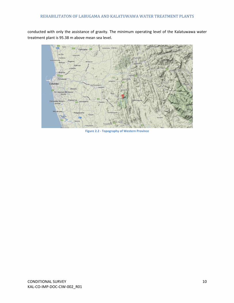
A general understanding of the topography of the region can be obtained from Figure 2.2. The strategic location of the Kalatuwawa water treatment plant allows the entire distribution procedure to be
REHABILITATON OF LABUGAMA AND KALATUWAWA WATER TREATMENT PLANTS
CONDITIONAL SURVEY 10 KAL-CO-IMP-DOC-CIW-002_R01
conducted with only the assistance of gravity. The minimum operating level of the Kalatuwawa water treatment plant is 95.38 m above mean sea level.
Figure 2.2 - Topography of Western Province

REHABILITATON OF LABUGAMA AND KALATUWAWA WATER TREATMENT PLANTS
CONDITIONAL SURVEY 11 KAL-CO-IMP-DOC-CIW-002_R01
3.
Raw Water Source
The Kalatuwawa reservoir is the foremost stage of supplying water to the people. Water purification can be very expensive and in order to provide a better quality drinking water at a low cost, it is essential to locate a quality raw water source. The Kalatuwawa reservoir receives its primary source of fresh water from a river called Wak Oya which is branch of the Kelani Ganga. The reservoir has a maximum capacity of 13.4 million m3 (3500 x 106 gallons).
The raw water source of Kalatuwawa is found to have the following basic water properties :
Figure 3.1 - Quality of raw water

REHABILITATON OF LABUGAMA AND KALATUWAWA WATER TREATMENT PLANTS
CONDITIONAL SURVEY 12 KAL-CO-IMP-DOC-CIW-002_R01
Figure 3.2 - Kalatuwawa Reservoir
Figure 3.2 shows the scenic view of the Kalatuwawa reservoir as seen from above the dam structure.
REHABILITATON OF LABUGAMA AND KALATUWAWA WATER TREATMENT PLANTS
CONDITIONAL SURVEY 13 KAL-CO-IMP-DOC-CIW-002_R01
4.
Kalatuwawa Gravity Dam
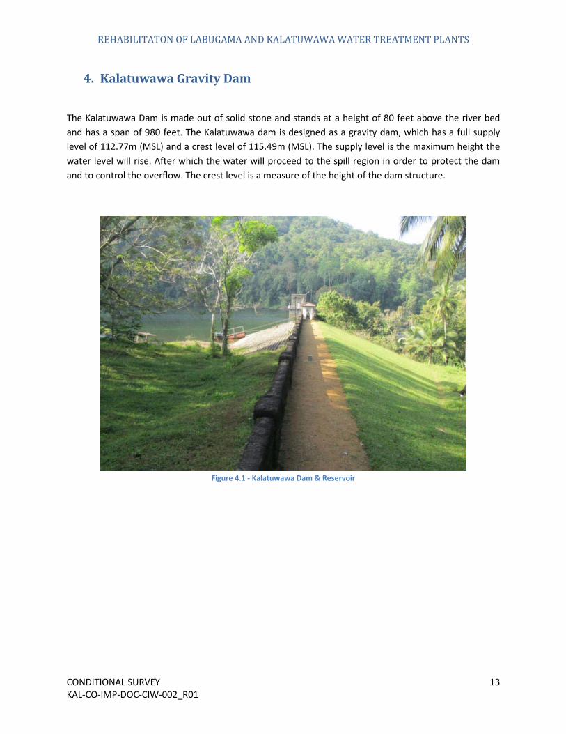
The Kalatuwawa Dam is made out of solid stone and stands at a height of 80 feet above the river bed and has a span of 980 feet. The Kalatuwawa dam is designed as a gravity dam, which has a full supply level of 112.77m (MSL) and a crest level of 115.49m (MSL). The supply level is the maximum height the water level will rise. After which the water will proceed to the spill region in order to protect the dam and to control the overflow. The crest level is a measure of the height of the dam structure.
Figure 4.1 - Kalatuwawa Dam & Reservoir
REHABILITATON OF LABUGAMA AND KALATUWAWA WATER TREATMENT PLANTS
CONDITIONAL SURVEY 14 KAL-CO-IMP-DOC-CIW-002_R01
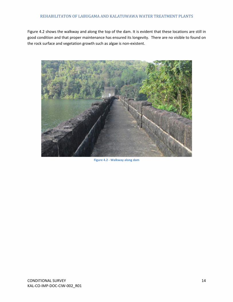
Figure 4.2 shows the walkway and along the top of the dam. It is evident that these locations are still in good condition and that proper maintenance has ensured its longevity. There are no visible to found on the rock surface and vegetation growth such as algae is non-existent.
Figure 4.2 - Walkway along dam
REHABILITATON OF LABUGAMA AND KALATUWAWA WATER TREATMENT PLANTS
CONDITIONAL SURVEY 15 KAL-CO-IMP-DOC-CIW-002_R01
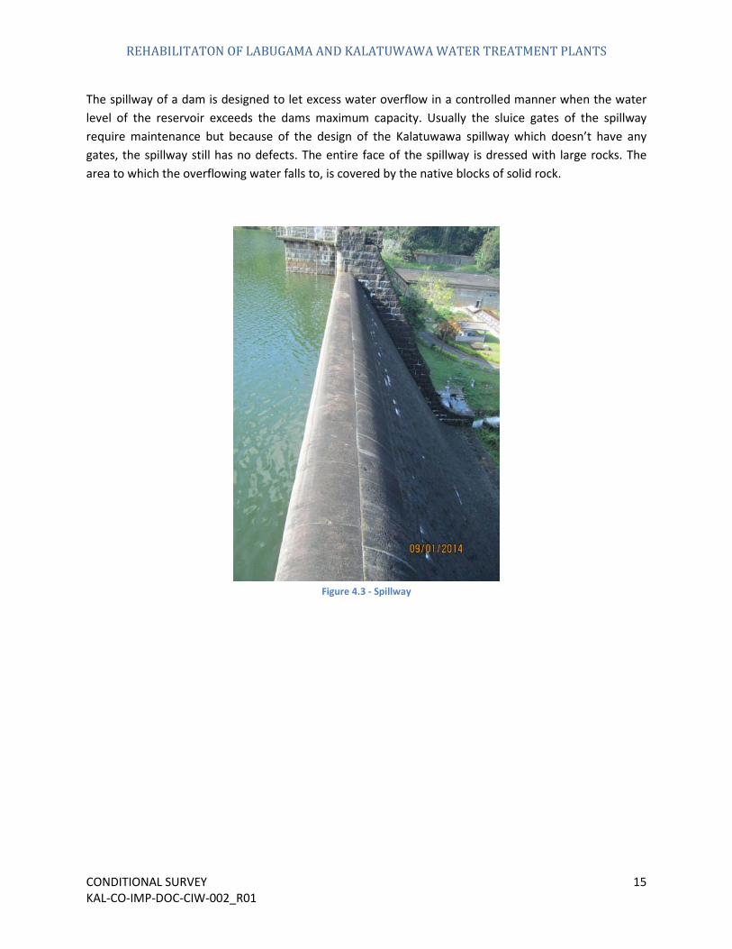
The spillway of a dam is designed to let excess water overflow in a controlled manner when the water level of the reservoir exceeds the dams maximum capacity. Usually the sluice gates of the spillway require maintenance but because of the design of the Kalatuwawa spillway which doesn’t have any gates, the spillway still has no defects. The entire face of the spillway is dressed with large rocks. The area to which the overflowing water falls to, is covered by the native blocks of solid rock.
Figure 4.3 - Spillway

REHABILITATON OF LABUGAMA AND KALATUWAWA WATER TREATMENT PLANTS
CONDITIONAL SURVEY 16 KAL-CO-IMP-DOC-CIW-002_R01
Two security outposts have been located on the walkway across the dam. Both of them have positioned on either side of the spillway. They provide only very basic facilities for the security officers and it can be seen that both units are in need of maintenance. These two outposts can be observed from Figure 4.4 and Figure 4.5.
Figure 4.4 - Security guard outpost I

REHABILITATON OF LABUGAMA AND KALATUWAWA WATER TREATMENT PLANTS
CONDITIONAL SURVEY 17 KAL-CO-IMP-DOC-CIW-002_R01
Figure 4.5 - Security guard outpost II
It can be clearly seen that the facilities inside these guard posts are inadequate. A graphic of the interior of one of the stations can be observed from Figure 4.6. The electrical system is seen to be disorganised and even basic facilities such as a chair is unavailable. Additionally no communication apparatus is present in this post. The main purpose of a security outpost such as this is to give a good location for the officer to see whether there are any malicious activities occurring in the area. But the design of this outpost is quite contradictory, as the type of windows used and the area of windows is insufficient to provide adequate visibility over the raw water source.

REHABILITATON OF LABUGAMA AND KALATUWAWA WATER TREATMENT PLANTS
CONDITIONAL SURVEY 18 KAL-CO-IMP-DOC-CIW-002_R01
Figure 4.6 - Interior of security guard outpost
There is an access to the reservoir on top of the dam. This area is fastened with handrails and chains to prevent unauthorized access. As these components are metallic, they are very susceptible to corrosion. Therefore it is advisable to conduct maintenance on these parts before serious corrosion sets in.

REHABILITATON OF LABUGAMA AND KALATUWAWA WATER TREATMENT PLANTS
CONDITIONAL SURVEY 19 KAL-CO-IMP-DOC-CIW-002_R01
Figure 4.7 - Handrails on the gravity dam
REHABILITATON OF LABUGAMA AND KALATUWAWA WATER TREATMENT PLANTS
CONDITIONAL SURVEY 20 KAL-CO-IMP-DOC-CIW-002_R01
5. Intake Well
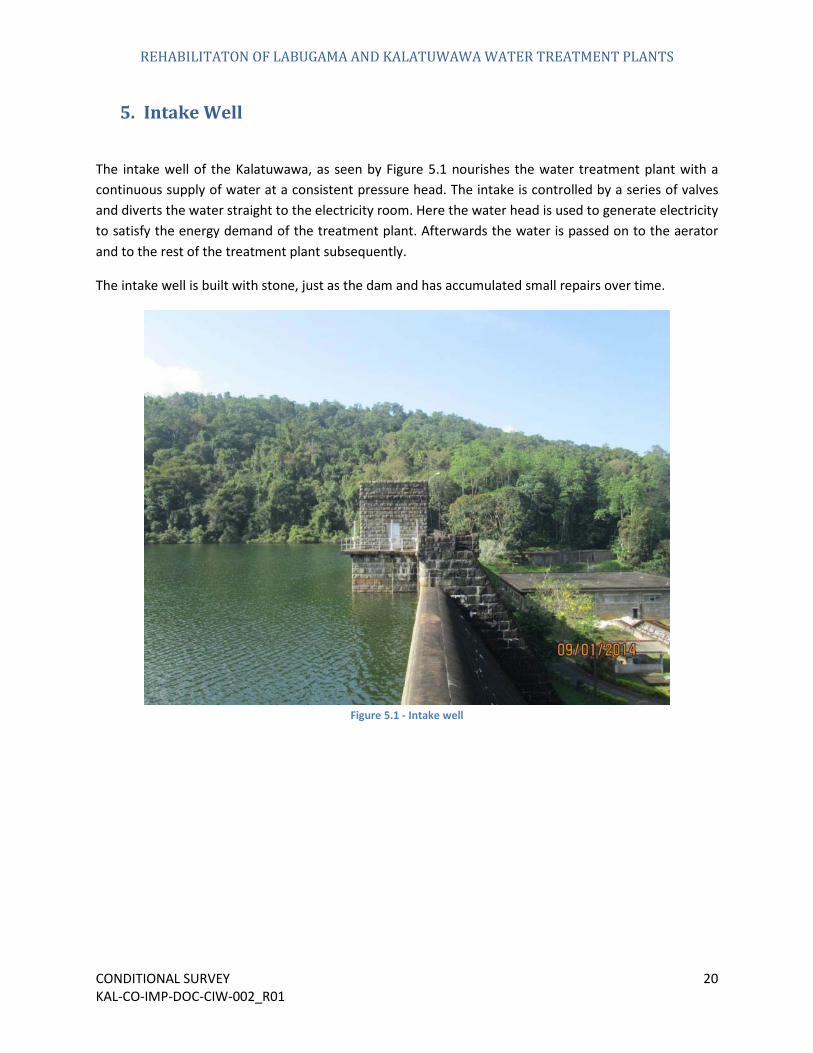
The intake well of the Kalatuwawa, as seen by Figure 5.1 nourishes the water treatment plant with a continuous supply of water at a consistent pressure head. The intake is controlled by a series of valves and diverts the water straight to the electricity room. Here the water head is used to generate electricity to satisfy the energy demand of the treatment plant. Afterwards the water is passed on to the aerator and to the rest of the treatment plant subsequently.
The intake well is built with stone, just as the dam and has accumulated small repairs over time.
Figure 5.1 - Intake well

REHABILITATON OF LABUGAMA AND KALATUWAWA WATER TREATMENT PLANTS
CONDITIONAL SURVEY 21 KAL-CO-IMP-DOC-CIW-002_R01
Figure 5.2 - Monitoring equipment of the intake well
Various monitoring equipment have been installed at the intake well. One apparatus functions to monitor the water level of the reservoir. These equipment need to be properly maintained. But as seen in Figure 5.2, they have been laid out in a very disorderly manner and the PVC pipes which acts as cover for the wires, is potentially a trip hazard if work ever needs to be conducted in a dark or wet environment.
This unsystematic arrangement can also be seen in the laying of the earth wire at the intake well. There is a relatively large earth wire placed in this location. This is to divert the electrical current from that area in case lightning shall ever strike. As seen in Figure 5.3, it is evident that there has not been a proper plan to install this piece of equipment. It too poses as a hazard in unsafe working conditions.
The earth wire is only covered by a delicate plastic covering which is not at all durable. Additionally it can be seen that it is exposed in certain areas. With respect to the excessive voltage and current it is expected to receive in a lightning strike, it can be marked as unsafe.

REHABILITATON OF LABUGAMA AND KALATUWAWA WATER TREATMENT PLANTS
CONDITIONAL SURVEY 22 KAL-CO-IMP-DOC-CIW-002_R01
Figure 5.3 - Earth wire of intake well
Even though the intake well has been upgraded once before, it is still in need of some degree of some sort of maintenance for the doors, windows and the handrails that surround the structure. As seen in Figure 5.4, these afore mentioned components are generally in an acceptable condition but further maintenance works will keep it in good condition.

REHABILITATON OF LABUGAMA AND KALATUWAWA WATER TREATMENT PLANTS
CONDITIONAL SURVEY 23 KAL-CO-IMP-DOC-CIW-002_R01
Figure 5.4 - Intake well exterior
REHABILITATON OF LABUGAMA AND KALATUWAWA WATER TREATMENT PLANTS
CONDITIONAL SURVEY 24 KAL-CO-IMP-DOC-CIW-002_R01
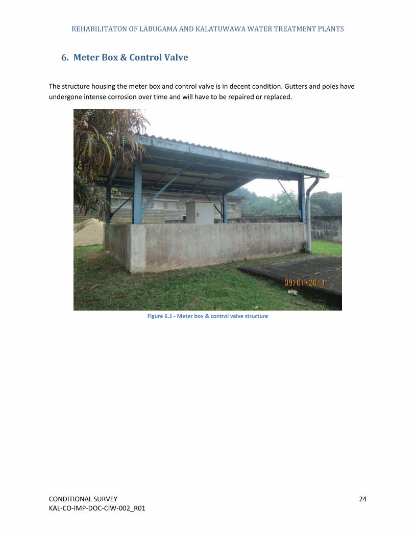
6. Meter Box & Control Valve
The structure housing the meter box and control valve is in decent condition. Gutters and poles have undergone intense corrosion over time and will have to be repaired or replaced.
Figure 6.1 - Meter box & control valve structure

REHABILITATON OF LABUGAMA AND KALATUWAWA WATER TREATMENT PLANTS
CONDITIONAL SURVEY 25 KAL-CO-IMP-DOC-CIW-002_R01
Figure 6.2 - Deteriorating roof
Figure 6.3 - Damaged roof & ridge tiles

REHABILITATON OF LABUGAMA AND KALATUWAWA WATER TREATMENT PLANTS
CONDITIONAL SURVEY 26 KAL-CO-IMP-DOC-CIW-002_R01
Figure 6.4 - Control valve I
Figure 6.5 - Control valves II

REHABILITATON OF LABUGAMA AND KALATUWAWA WATER TREATMENT PLANTS
CONDITIONAL SURVEY 27 KAL-CO-IMP-DOC-CIW-002_R01
Figure 6.6 - Checker plates
Figure 6.7 - Meter box

REHABILITATON OF LABUGAMA AND KALATUWAWA WATER TREATMENT PLANTS
CONDITIONAL SURVEY 28 KAL-CO-IMP-DOC-CIW-002_R01
Figure 6.8 - Drain pipes
Figure 6.9 - Poorly fixed electrical items

REHABILITATON OF LABUGAMA AND KALATUWAWA WATER TREATMENT PLANTS
CONDITIONAL SURVEY 29 KAL-CO-IMP-DOC-CIW-002_R01
7. Aerator
The first stage of purification initiates at the aerator. The main objective of the aerator is to thoroughly mix air with the raw water. By doing this it is able to dispel other gases such as carbon dioxide and chlorine which have been already dissolved in the water source.
Figure 7.1 shows the aerating unit which is operating at the Kalatuwawa water treatment plant. It is observable that the apparatus is still functional and has only undergone mild deterioration over the years.
Figure 7.1 - Water aerator
Even though the overall performance of this structure has been preserved, it has still undergone wear and tear. As seen in Figure 7.2, there is some degree of organic matter which is growing on the aerators. Small foliage and various sorts of algae can be identified on the metallic notches of the aerator. This could potentially affect the water quality of the water and gives a general degraded appearance to the water aerating unit.
The growth of vegetation including algae and other aquatic plants can be further observed from Figure 7.3. This is the general state of the aerator. Various sorts of vegetation have grown over it with time.

REHABILITATON OF LABUGAMA AND KALATUWAWA WATER TREATMENT PLANTS
CONDITIONAL SURVEY 30 KAL-CO-IMP-DOC-CIW-002_R01
Figure 7.2 - Vegetation growth on the aerator I
Figure 7.3 - Vegetation growth on the aerator II

REHABILITATON OF LABUGAMA AND KALATUWAWA WATER TREATMENT PLANTS
CONDITIONAL SURVEY 31 KAL-CO-IMP-DOC-CIW-002_R01
Figure 7.4 - Exterior wall of aerator
Figure 7.5 - Interior walls of aerator

REHABILITATON OF LABUGAMA AND KALATUWAWA WATER TREATMENT PLANTS
CONDITIONAL SURVEY 32 KAL-CO-IMP-DOC-CIW-002_R01
Besides the problems regarding the vegetation, the aerator also has unclean and unpainted exterior and interior walls. This also adds to the unpleasant and unprofessional appearance of the water treating unit. The Figure 7.4 depicts the current nature of the exterior walls.
Additionally the interior walls of the aerator have also not been painted. It is essential that it is painted in order to make it clearly visible, the surfaces that the water is in contact. Without this visibility it is difficult to identify any defects or cracks on the surface. It is also unclear to see where the vegetation is growing on the walls. This issue could easily be identified in Figure 7.5.
It is a short sighted approach to allow these surfaces to function without being properly painted, with the appropriate not toxic and insoluble paints, as maintenance will be costly as defects will only be able to be identified once it has propagated sufficiently. Therefore in order to implement an early detection process, the interior walls of the aerator must be improved.
Figure 7.6 - Cracks in aerator
Furthermore small cracks and leaks can be found on the walls of the aerating unit. Such an example can be observed from Figure 7.6. It is very advisable that these minor problems should be repaired as soon as possible before it is able to propagate. Otherwise a more significant cost will be incurred later when doing so.

REHABILITATON OF LABUGAMA AND KALATUWAWA WATER TREATMENT PLANTS
CONDITIONAL SURVEY 33 KAL-CO-IMP-DOC-CIW-002_R01
Figure 7.7 - Aerator access stairway
There is an access stairway to the aerator intake as shown by Figure 7.7. It is generally in good condition but there are some minor repairs to be done to reinstate it. The handrails have gone through some mild corrosion. Furthermore the handrails have been installed in an insecure scheme. There is one location as seen in Figure 7.8, near the intake of the aerator where there is a large gap between the handrails. This makes this location unsafe as an incautious visitor or technician could easily fall through it into the pit below.

REHABILITATON OF LABUGAMA AND KALATUWAWA WATER TREATMENT PLANTS
CONDITIONAL SURVEY 34 KAL-CO-IMP-DOC-CIW-002_R01
Figure 7.8 - Unsafe handrails near aerator structure
Figure 7.9 - Supply lines

REHABILITATON OF LABUGAMA AND KALATUWAWA WATER TREATMENT PLANTS
CONDITIONAL SURVEY 35 KAL-CO-IMP-DOC-CIW-002_R01
Figure 7.10 - Covers for piping
Figure 7.11 - Unorganised pipes I

REHABILITATON OF LABUGAMA AND KALATUWAWA WATER TREATMENT PLANTS
CONDITIONAL SURVEY 36 KAL-CO-IMP-DOC-CIW-002_R01
Figure 7.12 - Unorganised pipes II
Figure 7.13 - Unorganised pipes III

REHABILITATON OF LABUGAMA AND KALATUWAWA WATER TREATMENT PLANTS
CONDITIONAL SURVEY 37 KAL-CO-IMP-DOC-CIW-002_R01
Figure 7.14 - Primitive contraptions for alum distribution
Figure 7.15 - Waste material in the premises

REHABILITATON OF LABUGAMA AND KALATUWAWA WATER TREATMENT PLANTS
CONDITIONAL SURVEY 38 KAL-CO-IMP-DOC-CIW-002_R01
8. Chlorine Storage Building
The chlorination building as shown by Figure 8.1 is in a deteriorated condition. It is unsuitable for the new quality standards the renovation project will create.
Figure 8.1 - Chlorine storage building

REHABILITATON OF LABUGAMA AND KALATUWAWA WATER TREATMENT PLANTS
CONDITIONAL SURVEY 39 KAL-CO-IMP-DOC-CIW-002_R01
Figure 8.2 - Chemical storage building loading area
Figure 8.3 - Roofing structure

REHABILITATON OF LABUGAMA AND KALATUWAWA WATER TREATMENT PLANTS
CONDITIONAL SURVEY 40 KAL-CO-IMP-DOC-CIW-002_R01
Figure 8.4 - Water leakage
REHABILITATON OF LABUGAMA AND KALATUWAWA WATER TREATMENT PLANTS
CONDITIONAL SURVEY 41 KAL-CO-IMP-DOC-CIW-002_R01
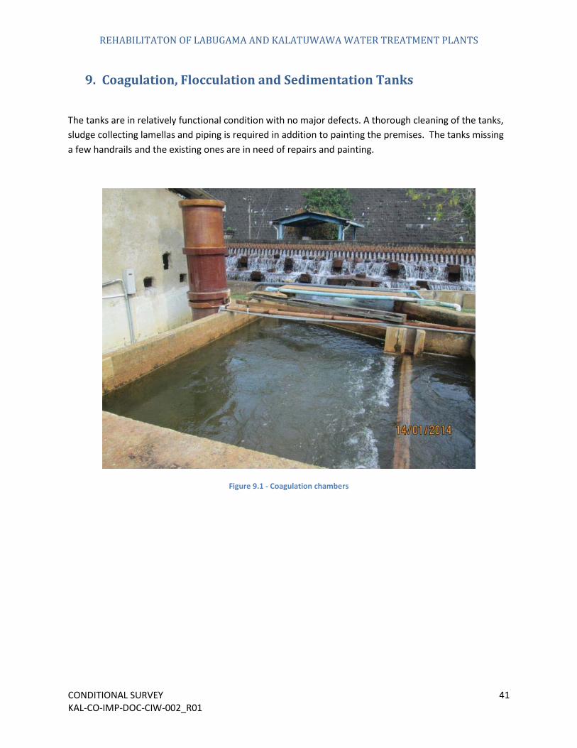
9. Coagulation, Flocculation and Sedimentation Tanks
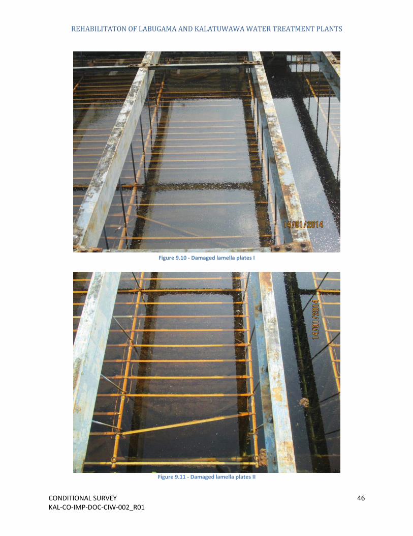
The tanks are in relatively functional condition with no major defects. A thorough cleaning of the tanks, sludge collecting lamellas and piping is required in addition to painting the premises. The tanks missing a few handrails and the existing ones are in need of repairs and painting.
Figure 9.1 - Coagulation chambers
REHABILITATON OF LABUGAMA AND KALATUWAWA WATER TREATMENT PLANTS
CONDITIONAL SURVEY 42 KAL-CO-IMP-DOC-CIW-002_R01
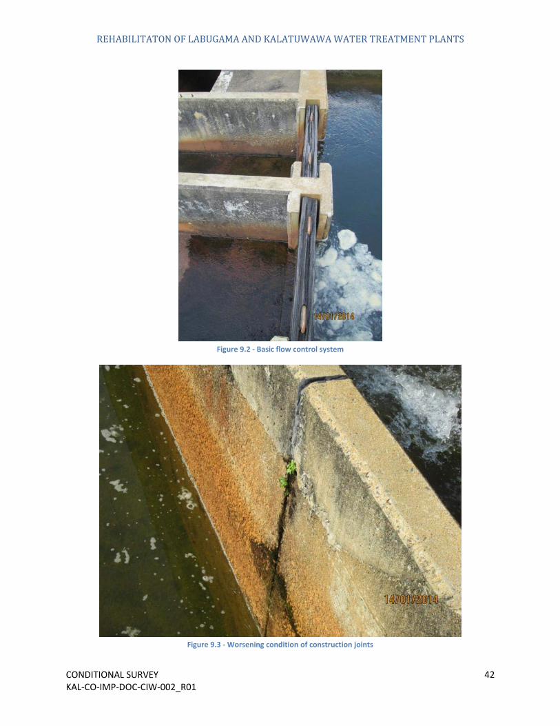
Figure 9.2 - Basic flow control system
Figure 9.3 - Worsening condition of construction joints

REHABILITATON OF LABUGAMA AND KALATUWAWA WATER TREATMENT PLANTS
CONDITIONAL SURVEY 43 KAL-CO-IMP-DOC-CIW-002_R01
Figure 9.4 - Unclean interior walls
Figure 9.5 - Unpainted interior walls

REHABILITATON OF LABUGAMA AND KALATUWAWA WATER TREATMENT PLANTS
CONDITIONAL SURVEY 44 KAL-CO-IMP-DOC-CIW-002_R01
Figure 9.6 - Exterior walls I
Figure 9.7 - Exterior walls II
REHABILITATON OF LABUGAMA AND KALATUWAWA WATER TREATMENT PLANTS
CONDITIONAL SURVEY 45 KAL-CO-IMP-DOC-CIW-002_R01
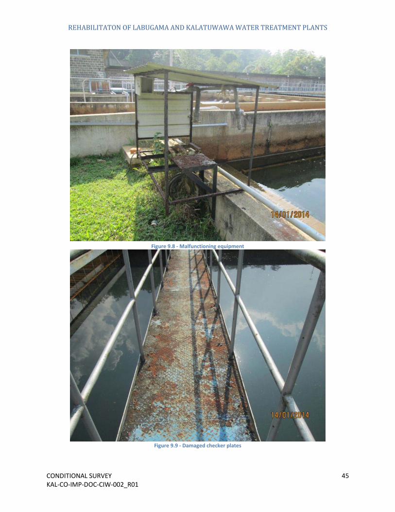
Figure 9.8 - Malfunctioning equipment
Figure 9.9 - Damaged checker plates
REHABILITATON OF LABUGAMA AND KALATUWAWA WATER TREATMENT PLANTS
CONDITIONAL SURVEY 46 KAL-CO-IMP-DOC-CIW-002_R01
Figure 9.10 - Damaged lamella plates I
Figure 9.11 - Damaged lamella plates II

REHABILITATON OF LABUGAMA AND KALATUWAWA WATER TREATMENT PLANTS
CONDITIONAL SURVEY 47 KAL-CO-IMP-DOC-CIW-002_R01
Figure 9.12 - Corrosion on existing horizontal frame
Figure 9.13 - Missing handrails

REHABILITATON OF LABUGAMA AND KALATUWAWA WATER TREATMENT PLANTS
CONDITIONAL SURVEY 48 KAL-CO-IMP-DOC-CIW-002_R01
Figure 9.14 - Makeshift works near on walkway
Figure 9.15 - Corrosion on existing handrails

REHABILITATON OF LABUGAMA AND KALATUWAWA WATER TREATMENT PLANTS
CONDITIONAL SURVEY 49 KAL-CO-IMP-DOC-CIW-002_R01
Figure 9.16 - Access stairway
Figure 9.17 - Makeshift lighting

REHABILITATON OF LABUGAMA AND KALATUWAWA WATER TREATMENT PLANTS
CONDITIONAL SURVEY 50 KAL-CO-IMP-DOC-CIW-002_R01
Figure 9.18 - Sedimentation tank without a roof
Figure 9.19 - Makeshift apparatus

REHABILITATON OF LABUGAMA AND KALATUWAWA WATER TREATMENT PLANTS
CONDITIONAL SURVEY 51 KAL-CO-IMP-DOC-CIW-002_R01
10. Sand Filters
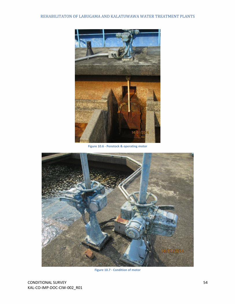
The performance of the existing filters has been reduced over time and in need of major improvements. Moreover the area lacks hand rails along the walkways and has wiring running along them. These factors contribute towards creating an unsafe working environment.
Figure 10.1 - Sand filter structure

REHABILITATON OF LABUGAMA AND KALATUWAWA WATER TREATMENT PLANTS
CONDITIONAL SURVEY 52 KAL-CO-IMP-DOC-CIW-002_R01
Figure 10.2 - Rapid sand filter
Figure 10.3 - Sand filter media I

REHABILITATON OF LABUGAMA AND KALATUWAWA WATER TREATMENT PLANTS
CONDITIONAL SURVEY 53 KAL-CO-IMP-DOC-CIW-002_R01
Figure 10.4 - Sand filter media II
Figure 10.5 - Sand filter media III
REHABILITATON OF LABUGAMA AND KALATUWAWA WATER TREATMENT PLANTS
CONDITIONAL SURVEY 54 KAL-CO-IMP-DOC-CIW-002_R01
Figure 10.6 - Penstock & operating motor
Figure 10.7 - Condition of motor

REHABILITATON OF LABUGAMA AND KALATUWAWA WATER TREATMENT PLANTS
CONDITIONAL SURVEY 55 KAL-CO-IMP-DOC-CIW-002_R01
Figure 10.8 - Brick partition and piping
Figure 10.9 - Water channel in filter structure

REHABILITATON OF LABUGAMA AND KALATUWAWA WATER TREATMENT PLANTS
CONDITIONAL SURVEY 56 KAL-CO-IMP-DOC-CIW-002_R01
Figure 10.10 - Electric wiring systems
Figure 10.11 - Access way

REHABILITATON OF LABUGAMA AND KALATUWAWA WATER TREATMENT PLANTS
CONDITIONAL SURVEY 57 KAL-CO-IMP-DOC-CIW-002_R01
Figure 10.12 - Makeshift works

REHABILITATON OF LABUGAMA AND KALATUWAWA WATER TREATMENT PLANTS
CONDITIONAL SURVEY 58 KAL-CO-IMP-DOC-CIW-002_R01
11. Filter Gallery
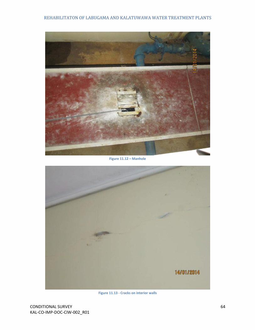
The filter gallery is in overall acceptable condition. Only minor repairs, cleaning and painting need to be carried out. There are some leaks in the pipes lining the walls as shown in Figure 11.7. These need to be also fixed
Figure 11.1 - Filter Gallery

REHABILITATON OF LABUGAMA AND KALATUWAWA WATER TREATMENT PLANTS
CONDITIONAL SURVEY 59 KAL-CO-IMP-DOC-CIW-002_R01
Figure 11.2 - Electrical works I
Figure 11.3 - Electrical works II

REHABILITATON OF LABUGAMA AND KALATUWAWA WATER TREATMENT PLANTS
CONDITIONAL SURVEY 60 KAL-CO-IMP-DOC-CIW-002_R01
Figure 11.4 - Access ladder
Figure 11.5 – Leaks

REHABILITATON OF LABUGAMA AND KALATUWAWA WATER TREATMENT PLANTS
CONDITIONAL SURVEY 61 KAL-CO-IMP-DOC-CIW-002_R01
Figure 11.6 - Leaks on floor
Figure 11.7 - Leaks on interior walls

REHABILITATON OF LABUGAMA AND KALATUWAWA WATER TREATMENT PLANTS
CONDITIONAL SURVEY 62 KAL-CO-IMP-DOC-CIW-002_R01
Figure 11.8 – Handrails
Figure 11.9 - Construction joints

REHABILITATON OF LABUGAMA AND KALATUWAWA WATER TREATMENT PLANTS
CONDITIONAL SURVEY 63 KAL-CO-IMP-DOC-CIW-002_R01
Figure 11.10 – Doorway
Figure 11.11 - Shattered windows
REHABILITATON OF LABUGAMA AND KALATUWAWA WATER TREATMENT PLANTS
CONDITIONAL SURVEY 64 KAL-CO-IMP-DOC-CIW-002_R01
Figure 11.12 – Manhole
Figure 11.13 - Cracks on interior walls

REHABILITATON OF LABUGAMA AND KALATUWAWA WATER TREATMENT PLANTS
CONDITIONAL SURVEY 65 KAL-CO-IMP-DOC-CIW-002_R01
12. Chemical Storage Building
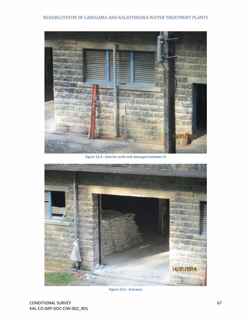
The chemical building requires renovation in order to bring it up to the new agreed quality standards. Major clean-up of the building is required in order to operate this building properly. In its current state it is unorganized and waste materials have accumulated over time. There are items to be removed from the premise as shown in
Figure 12.1 - Chemical storage building

REHABILITATON OF LABUGAMA AND KALATUWAWA WATER TREATMENT PLANTS
CONDITIONAL SURVEY 66 KAL-CO-IMP-DOC-CIW-002_R01
Figure 12.2 - Exterior walls and damaged windows I
Figure 12.3 - Exterior walls and damaged windows II
REHABILITATON OF LABUGAMA AND KALATUWAWA WATER TREATMENT PLANTS
CONDITIONAL SURVEY 67 KAL-CO-IMP-DOC-CIW-002_R01
Figure 12.4 - Exterior walls and damaged windows III
Figure 12.5 - Entrance

REHABILITATON OF LABUGAMA AND KALATUWAWA WATER TREATMENT PLANTS
CONDITIONAL SURVEY 68 KAL-CO-IMP-DOC-CIW-002_R01
Figure 12.6 - Roller door
Figure 12.7 - Entrance & steel beams
REHABILITATON OF LABUGAMA AND KALATUWAWA WATER TREATMENT PLANTS
CONDITIONAL SURVEY 69 KAL-CO-IMP-DOC-CIW-002_R01
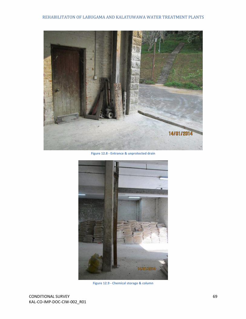
Figure 12.8 - Entrance & unprotected drain
Figure 12.9 - Chemical storage & column
REHABILITATON OF LABUGAMA AND KALATUWAWA WATER TREATMENT PLANTS
CONDITIONAL SURVEY 70 KAL-CO-IMP-DOC-CIW-002_R01
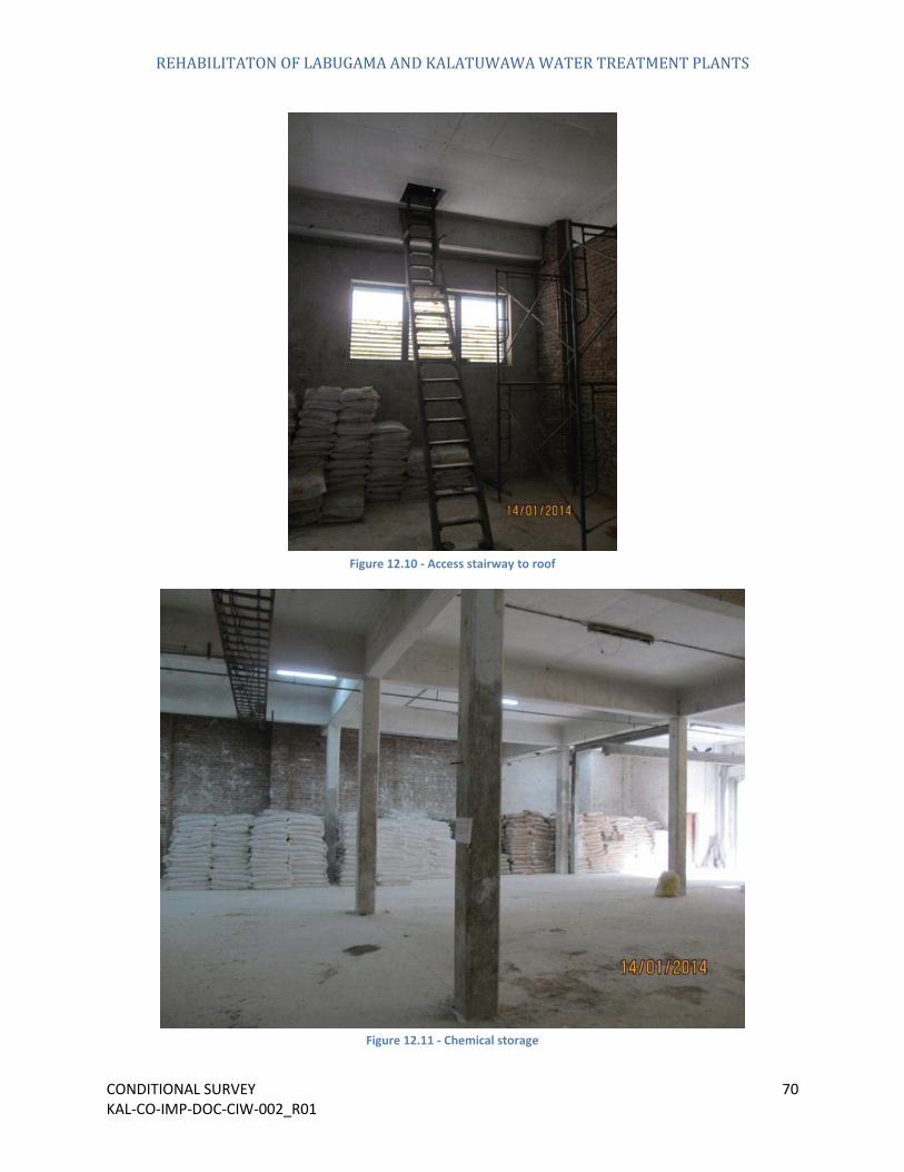
Figure 12.10 - Access stairway to roof
Figure 12.11 - Chemical storage

REHABILITATON OF LABUGAMA AND KALATUWAWA WATER TREATMENT PLANTS
CONDITIONAL SURVEY 71 KAL-CO-IMP-DOC-CIW-002_R01
Figure 12.12 - Cable trays
Figure 12.13 - Electrical fittings I

REHABILITATON OF LABUGAMA AND KALATUWAWA WATER TREATMENT PLANTS
CONDITIONAL SURVEY 72 KAL-CO-IMP-DOC-CIW-002_R01
Figure 12.14 - Electrical fittings II
Figure 12.15 - Cracks on the ceiling

REHABILITATON OF LABUGAMA AND KALATUWAWA WATER TREATMENT PLANTS
CONDITIONAL SURVEY 73 KAL-CO-IMP-DOC-CIW-002_R01
Figure 12.16 - Old weighing scale
Figure 12.17 - Non-operational lime adding chamber

REHABILITATON OF LABUGAMA AND KALATUWAWA WATER TREATMENT PLANTS
CONDITIONAL SURVEY 74 KAL-CO-IMP-DOC-CIW-002_R01
Figure 12.18 - Lime adding chamber
Figure 12.19 - Corroded metal surface
REHABILITATON OF LABUGAMA AND KALATUWAWA WATER TREATMENT PLANTS
CONDITIONAL SURVEY 75 KAL-CO-IMP-DOC-CIW-002_R01
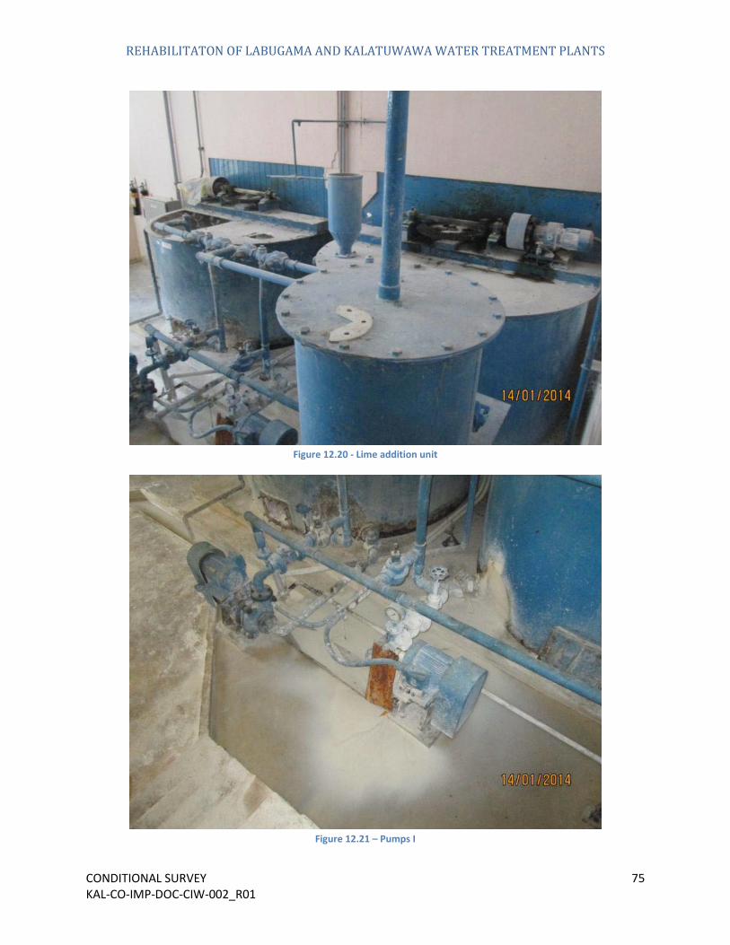
Figure 12.20 - Lime addition unit
Figure 12.21 – Pumps I

REHABILITATON OF LABUGAMA AND KALATUWAWA WATER TREATMENT PLANTS
CONDITIONAL SURVEY 76 KAL-CO-IMP-DOC-CIW-002_R01
Figure 12.22 - Pumps II
Figure 12.23 - Unclean surfaces

REHABILITATON OF LABUGAMA AND KALATUWAWA WATER TREATMENT PLANTS
CONDITIONAL SURVEY 77 KAL-CO-IMP-DOC-CIW-002_R01
Figure 12.24 - Lime mixing chamber
Figure 12.25 - Mechanical components of lime mixing chamber

REHABILITATON OF LABUGAMA AND KALATUWAWA WATER TREATMENT PLANTS
CONDITIONAL SURVEY 78 KAL-CO-IMP-DOC-CIW-002_R01
Figure 12.26 - Alum mixing chambers I
Figure 12.27 - Alum mixing chambers II

REHABILITATON OF LABUGAMA AND KALATUWAWA WATER TREATMENT PLANTS
CONDITIONAL SURVEY 79 KAL-CO-IMP-DOC-CIW-002_R01
Figure 12.28 - Alum mixing chambers III
Figure 12.29 - Corroded and leaking pipe

REHABILITATON OF LABUGAMA AND KALATUWAWA WATER TREATMENT PLANTS
CONDITIONAL SURVEY 80 KAL-CO-IMP-DOC-CIW-002_R01
Figure 12.30 – Piping works
Figure 12.31 - Leaks in pipes

REHABILITATON OF LABUGAMA AND KALATUWAWA WATER TREATMENT PLANTS
CONDITIONAL SURVEY 81 KAL-CO-IMP-DOC-CIW-002_R01
Figure 12.32 - Discoloured interior walls
Figure 12.33 - Unusable equipment

REHABILITATON OF LABUGAMA AND KALATUWAWA WATER TREATMENT PLANTS
CONDITIONAL SURVEY 82 KAL-CO-IMP-DOC-CIW-002_R01
13. Back Wash Water Tank
Figure 13.1 - Back wash water tank I

REHABILITATON OF LABUGAMA AND KALATUWAWA WATER TREATMENT PLANTS
CONDITIONAL SURVEY 83 KAL-CO-IMP-DOC-CIW-002_R01
Figure 13.2 - Back wash water tank II
REHABILITATON OF LABUGAMA AND KALATUWAWA WATER TREATMENT PLANTS
CONDITIONAL SURVEY 84 KAL-CO-IMP-DOC-CIW-002_R01
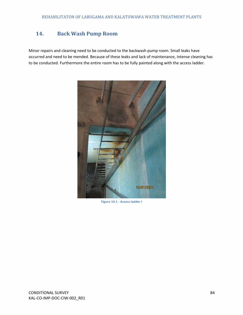
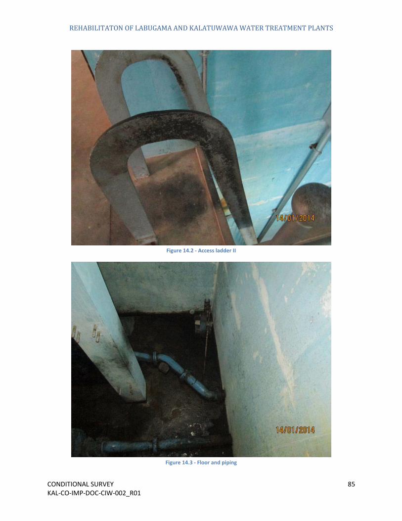
14. Back Wash Pump Room
Minor repairs and cleaning need to be conducted to the backwash pump room. Small leaks have occurred and need to be mended. Because of these leaks and lack of maintenance, intense cleaning has to be conducted. Furthermore the entire room has to be fully painted along with the access ladder.
Figure 14.1 - Access ladder I
REHABILITATON OF LABUGAMA AND KALATUWAWA WATER TREATMENT PLANTS
CONDITIONAL SURVEY 85 KAL-CO-IMP-DOC-CIW-002_R01
Figure 14.2 - Access ladder II
Figure 14.3 - Floor and piping

REHABILITATON OF LABUGAMA AND KALATUWAWA WATER TREATMENT PLANTS
CONDITIONAL SURVEY 86 KAL-CO-IMP-DOC-CIW-002_R01
Figure 14.4 - Pumps & pipes
Figure 14.5 - Discoloured interior walls and ladder

REHABILITATON OF LABUGAMA AND KALATUWAWA WATER TREATMENT PLANTS
CONDITIONAL SURVEY 87 KAL-CO-IMP-DOC-CIW-002_R01
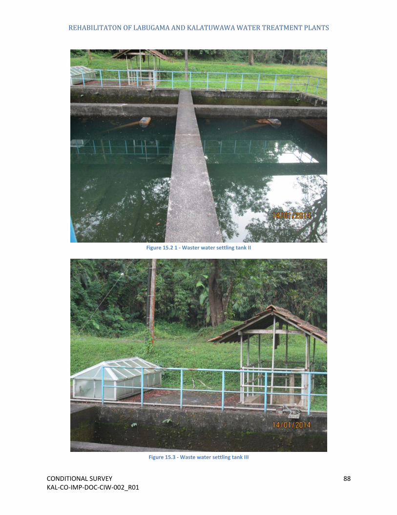
15. Waste Water Settling Tank
The wastewater settling tank is in a functional state but minor works such as cleaning and repainting the guardrails is required to bring it to a satisfactory standard.
Figure 15.1 - Waster water settling tank I
REHABILITATON OF LABUGAMA AND KALATUWAWA WATER TREATMENT PLANTS
CONDITIONAL SURVEY 88 KAL-CO-IMP-DOC-CIW-002_R01
Figure 15.2 1 - Waster water settling tank II
Figure 15.3 - Waste water settling tank III

REHABILITATON OF LABUGAMA AND KALATUWAWA WATER TREATMENT PLANTS
CONDITIONAL SURVEY 89 KAL-CO-IMP-DOC-CIW-002_R01
Figure 15.4 – Room
REHABILITATON OF LABUGAMA AND KALATUWAWA WATER TREATMENT PLANTS
CONDITIONAL SURVEY 90 KAL-CO-IMP-DOC-CIW-002_R01
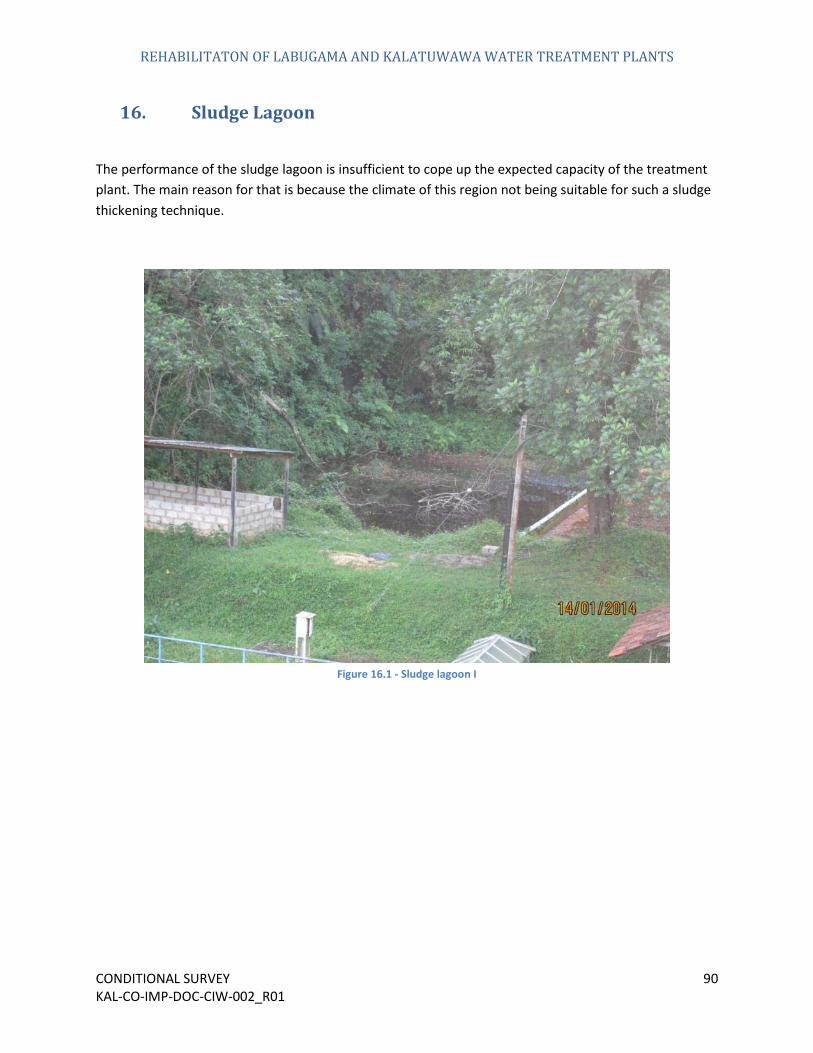
16. Sludge Lagoon
The performance of the sludge lagoon is insufficient to cope up the expected capacity of the treatment plant. The main reason for that is because the climate of this region not being suitable for such a sludge thickening technique.
Figure 16.1 - Sludge lagoon I

REHABILITATON OF LABUGAMA AND KALATUWAWA WATER TREATMENT PLANTS
CONDITIONAL SURVEY 91 KAL-CO-IMP-DOC-CIW-002_R01
Figure 16.2 - Sludge lagoon II
Figure 16.3 - Sludge lagoon III
REHABILITATON OF LABUGAMA AND KALATUWAWA WATER TREATMENT PLANTS
CONDITIONAL SURVEY 92 KAL-CO-IMP-DOC-CIW-002_R01
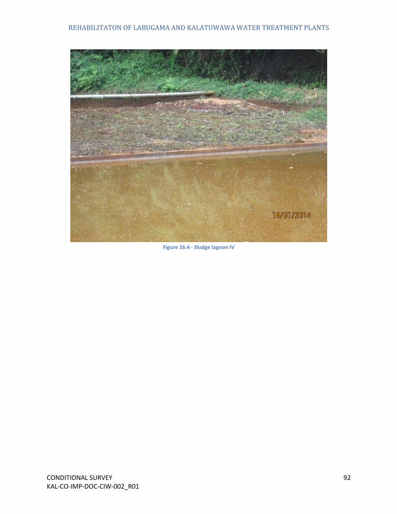
Figure 16.4 - Sludge lagoon IV
REHABILITATON OF LABUGAMA AND KALATUWAWA WATER TREATMENT PLANTS
CONDITIONAL SURVEY 93 KAL-CO-IMP-DOC-CIW-002_R01
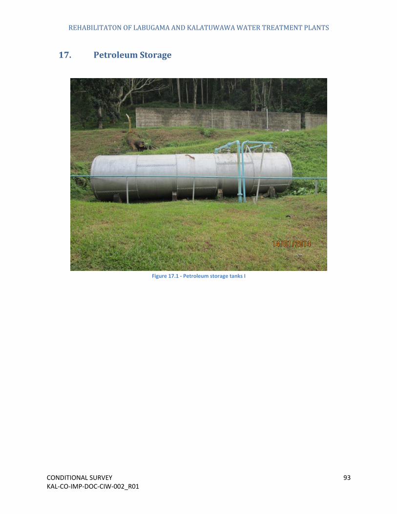
17. Petroleum Storage
Figure 17.1 - Petroleum storage tanks I

REHABILITATON OF LABUGAMA AND KALATUWAWA WATER TREATMENT PLANTS
CONDITIONAL SURVEY 94 KAL-CO-IMP-DOC-CIW-002_R01
Figure 17.2 - Petroleum storage tanks II
Figure 17.3 - Petroleum storage tanks III
REHABILITATON OF LABUGAMA AND KALATUWAWA WATER TREATMENT PLANTS
CONDITIONAL SURVEY 95 KAL-CO-IMP-DOC-CIW-002_R01
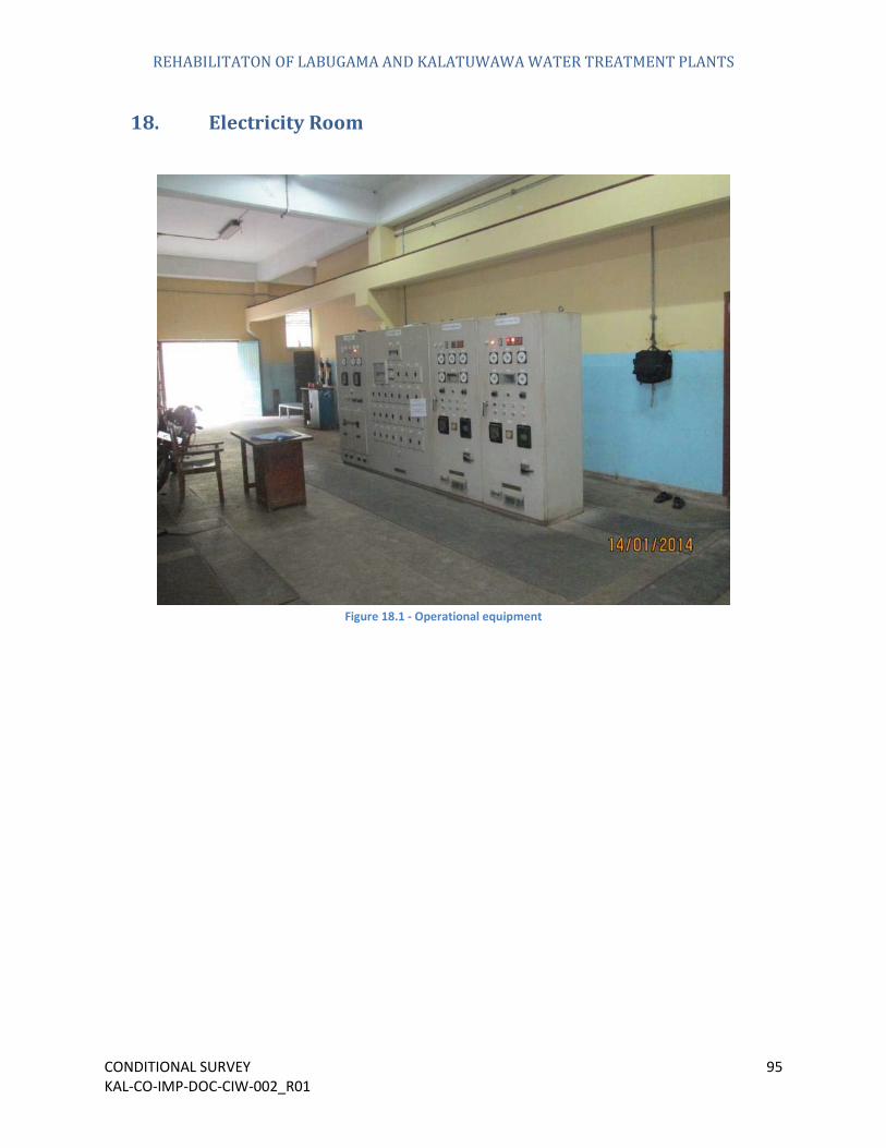
18. Electricity Room
Figure 18.1 - Operational equipment

REHABILITATON OF LABUGAMA AND KALATUWAWA WATER TREATMENT PLANTS
CONDITIONAL SURVEY 96 KAL-CO-IMP-DOC-CIW-002_R01
Figure 18.2 - Makeshift partition
Figure 18.3 - Hydro turbines

REHABILITATON OF LABUGAMA AND KALATUWAWA WATER TREATMENT PLANTS
CONDITIONAL SURVEY 97 KAL-CO-IMP-DOC-CIW-002_R01
Figure 18.4 - Gantry crane section
Figure 18.5 - Backup generator and petroleum barrels
REHABILITATON OF LABUGAMA AND KALATUWAWA WATER TREATMENT PLANTS
CONDITIONAL SURVEY 98 KAL-CO-IMP-DOC-CIW-002_R01
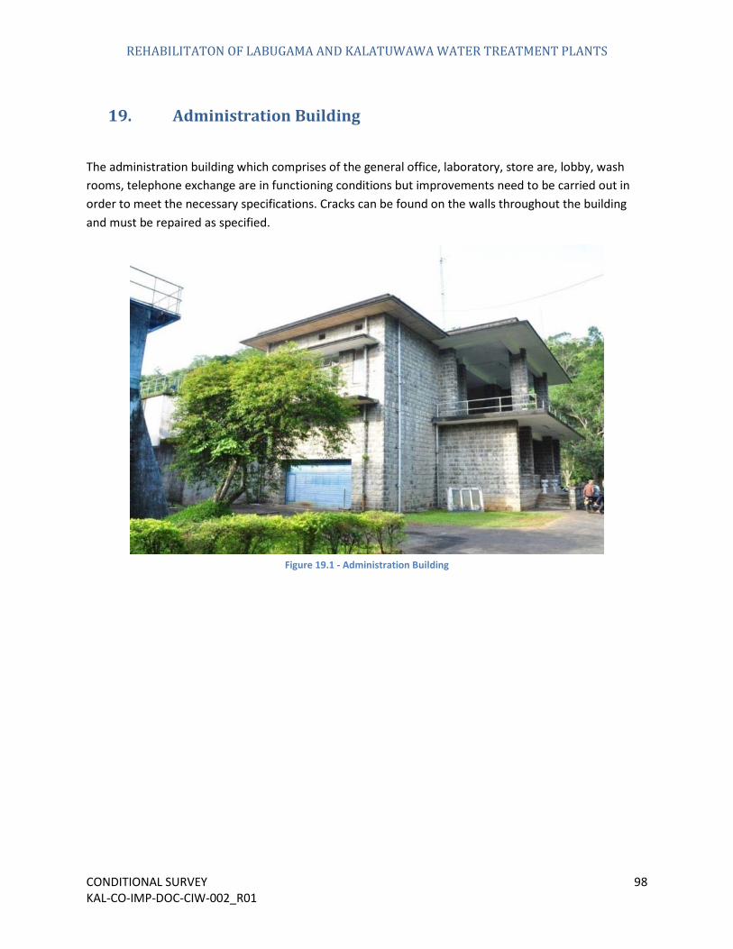
19. Administration Building
The administration building which comprises of the general office, laboratory, store are, lobby, wash rooms, telephone exchange are in functioning conditions but improvements need to be carried out in order to meet the necessary specifications. Cracks can be found on the walls throughout the building and must be repaired as specified.
Figure 19.1 - Administration Building

REHABILITATON OF LABUGAMA AND KALATUWAWA WATER TREATMENT PLANTS
CONDITIONAL SURVEY 99 KAL-CO-IMP-DOC-CIW-002_R01
Figure 19.2 - Cracks in the Administration Building
REHABILITATON OF LABUGAMA AND KALATUWAWA WATER TREATMENT PLANTS
CONDITIONAL SURVEY 100 KAL-CO-IMP-DOC-CIW-002_R01
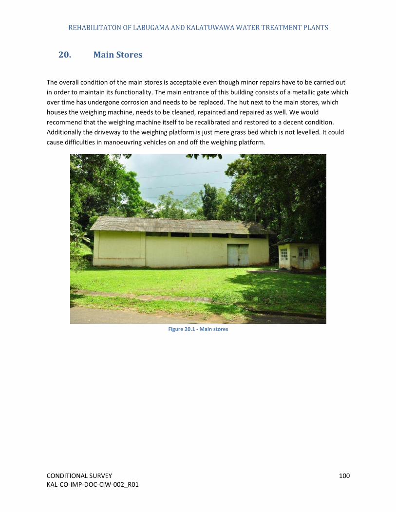
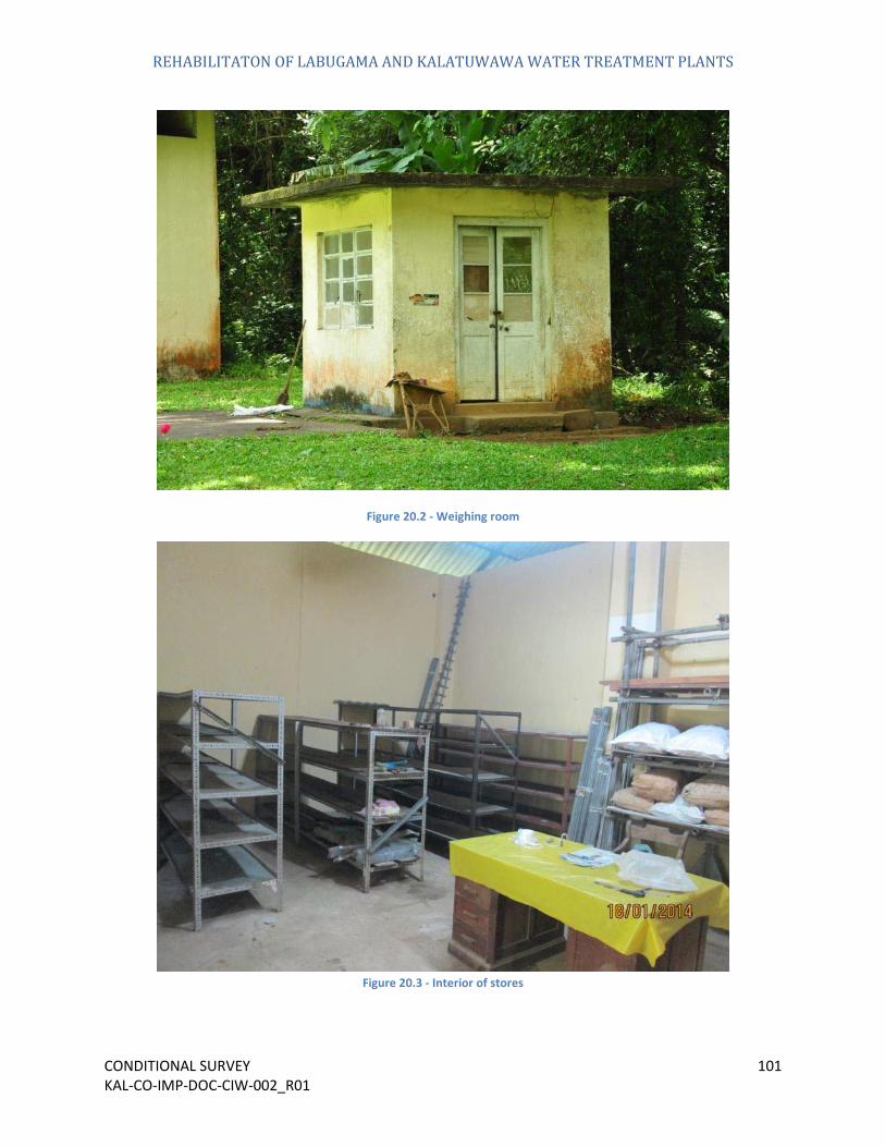
20. Main Stores
The overall condition of the main stores is acceptable even though minor repairs have to be carried out in order to maintain its functionality. The main entrance of this building consists of a metallic gate which over time has undergone corrosion and needs to be replaced. The hut next to the main stores, which houses the weighing machine, needs to be cleaned, repainted and repaired as well. We would recommend that the weighing machine itself to be recalibrated and restored to a decent condition. Additionally the driveway to the weighing platform is just mere grass bed which is not levelled. It could cause difficulties in manoeuvring vehicles on and off the weighing platform.
Figure 20.1 - Main stores
REHABILITATON OF LABUGAMA AND KALATUWAWA WATER TREATMENT PLANTS
CONDITIONAL SURVEY 101 KAL-CO-IMP-DOC-CIW-002_R01
Figure 20.2 - Weighing room
Figure 20.3 - Interior of stores
REHABILITATON OF LABUGAMA AND KALATUWAWA WATER TREATMENT PLANTS
CONDITIONAL SURVEY 102 KAL-CO-IMP-DOC-CIW-002_R01
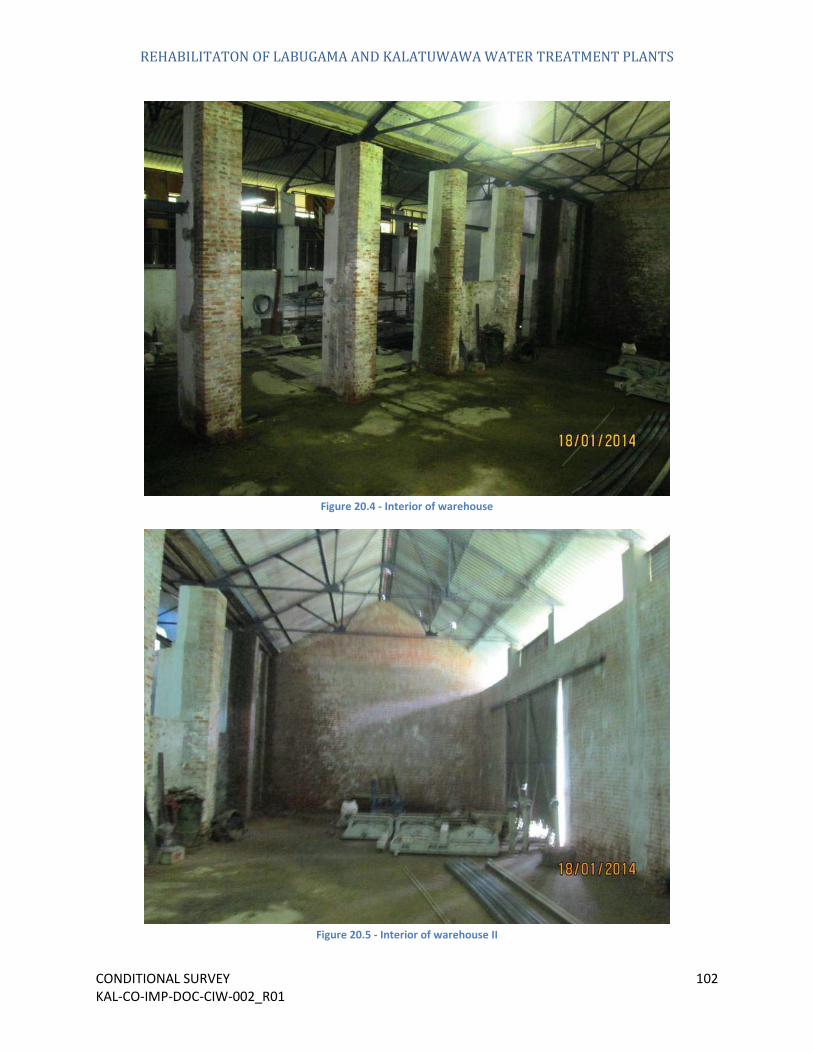
Figure 20.4 - Interior of warehouse
Figure 20.5 - Interior of warehouse II
REHABILITATON OF LABUGAMA AND KALATUWAWA WATER TREATMENT PLANTS
CONDITIONAL SURVEY 103 KAL-CO-IMP-DOC-CIW-002_R01
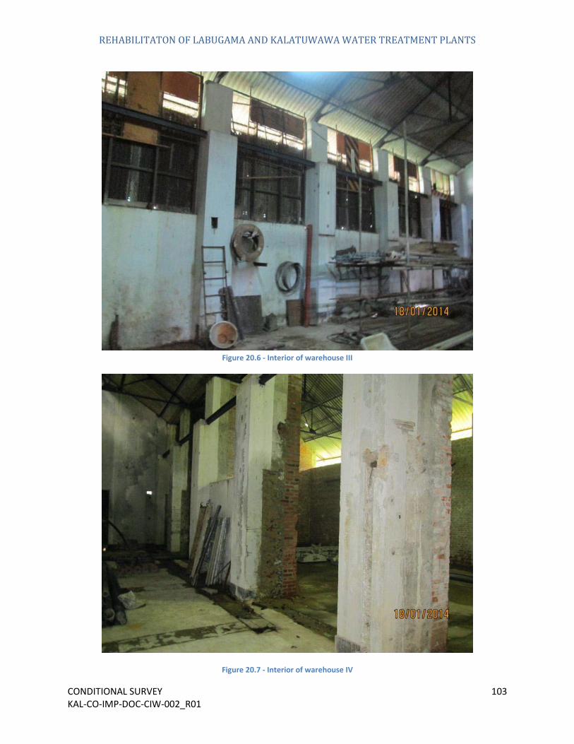
Figure 20.6 - Interior of warehouse III
Figure 20.7 - Interior of warehouse IV

REHABILITATON OF LABUGAMA AND KALATUWAWA WATER TREATMENT PLANTS
CONDITIONAL SURVEY 104 KAL-CO-IMP-DOC-CIW-002_R01
Figure 20.8 - Interior of warehouse V

REHABILITATON OF LABUGAMA AND KALATUWAWA WATER TREATMENT PLANTS
CONDITIONAL SURVEY 105 KAL-CO-IMP-DOC-CIW-002_R01
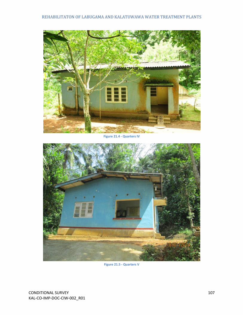
21. Quarters
The quarters are in a very rundown condition and in need of repairs, thorough cleaning and painting. Vegetation has grown along the houses as seen Figure 21.1.
Figure 21.1 - Quarters I

REHABILITATON OF LABUGAMA AND KALATUWAWA WATER TREATMENT PLANTS
CONDITIONAL SURVEY 106 KAL-CO-IMP-DOC-CIW-002_R01
Figure 21.2 - Quarters II
Figure 21.3 - Quarters III
REHABILITATON OF LABUGAMA AND KALATUWAWA WATER TREATMENT PLANTS
CONDITIONAL SURVEY 107 KAL-CO-IMP-DOC-CIW-002_R01
Figure 21.4 - Quarters IV
Figure 21.5 - Quarters V

REHABILITATON OF LABUGAMA AND KALATUWAWA WATER TREATMENT PLANTS
CONDITIONAL SURVEY 108 KAL-CO-IMP-DOC-CIW-002_R01
Figure 21.6 - Quarters VI
Figure 21.7 - Quarters VII

REHABILITATON OF LABUGAMA AND KALATUWAWA WATER TREATMENT PLANTS
CONDITIONAL SURVEY 109 KAL-CO-IMP-DOC-CIW-002_R01
Figure 21.8 - Navy quarters I
Figure 21.9 - Navy quarters II
REHABILITATON OF LABUGAMA AND KALATUWAWA WATER TREATMENT PLANTS
CONDITIONAL SURVEY 110 KAL-CO-IMP-DOC-CIW-002_R01
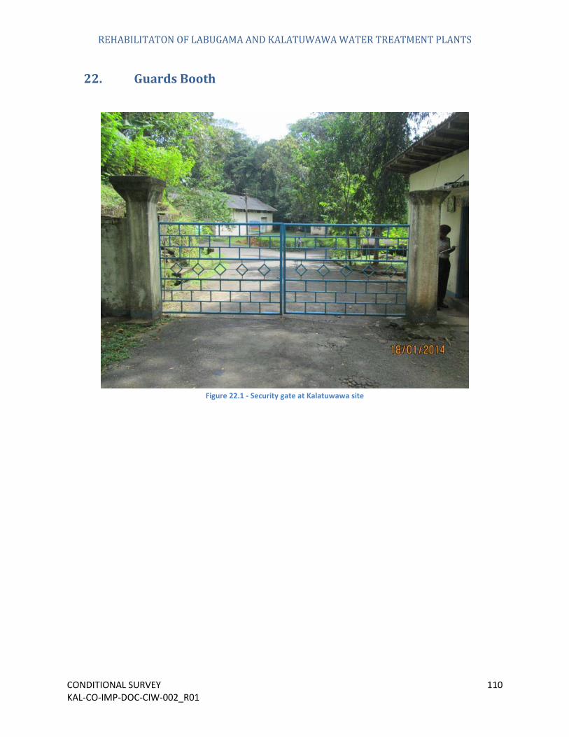
22. Guards Booth
Figure 22.1 - Security gate at Kalatuwawa site

REHABILITATON OF LABUGAMA AND KALATUWAWA WATER TREATMENT PLANTS
CONDITIONAL SURVEY 111 KAL-CO-IMP-DOC-CIW-002_R01
Figure 22.2 - Security booth
Figure 22.3 - Interior of security booth

REHABILITATON OF LABUGAMA AND KALATUWAWA WATER TREATMENT PLANTS
CONDITIONAL SURVEY 112 KAL-CO-IMP-DOC-CIW-002_R01
Figure 22.4 - Exterior of security booth

REHABILITATON OF LABUGAMA AND KALATUWAWA WATER TREATMENT PLANTS
CONDITIONAL SURVEY 113 KAL-CO-IMP-DOC-CIW-002_R01
24. Parking Garage
The parking garage which is situated opposite to the old water board office can be used to park a maximum of 03 vehicles. It has been designed with a high roof in order to accommodate heavy vehicles. But over time it has gone under deterioration and is need of a few minor repairs.
As seen in Figure 24.1 and Figure 24.2, there isn’t adequate protection for the vehicles from the weather. Because of its basic design the effects of the weather such as heavy weather and sunshine cannot be blocked by the garage.
Figure 24.1 - Parking garage I

REHABILITATON OF LABUGAMA AND KALATUWAWA WATER TREATMENT PLANTS
CONDITIONAL SURVEY 114 KAL-CO-IMP-DOC-CIW-002_R01
Figure 24.2 - Parking garage II

REHABILITATON OF LABUGAMA AND KALATUWAWA WATER TREATMENT PLANTS
CONDITIONAL SURVEY 115 KAL-CO-IMP-DOC-CIW-002_R01
25. Landscaping & Road Works
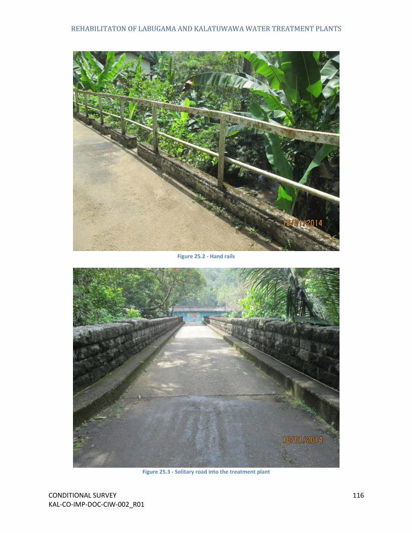
The landscaping works of the Kalatuwawa site have been maintained to a great degree. The roads are still usable and vegetation growth has been controlled. There is still room for improvement though. As seen in Figure 25.2 the hand rails has lost its lustre and physically does not look up to standard. Such minor issues give an unprofessional appearance to the treatment plant.
The road which leads to the treatment plant is in good condition as is the small stone arch bridge. It has adequate width to transport heavy vehicles. Currently this road is used is used to transport the large chlorine gas cylinders and so far no issues have been observed so far.
Figure 25.1 - Main access road
REHABILITATON OF LABUGAMA AND KALATUWAWA WATER TREATMENT PLANTS
CONDITIONAL SURVEY 116 KAL-CO-IMP-DOC-CIW-002_R01
Figure 25.2 - Hand rails
Figure 25.3 - Solitary road into the treatment plant