concrete pipe - installation guide
TRANSCRIPT

8/7/2019 Concrete Pipe - Installation Guide
http://slidepdf.com/reader/full/concrete-pipe-installation-guide 1/91
CONCRETE PIPE
&BOX CULVERT
INSTALLATION

8/7/2019 Concrete Pipe - Installation Guide
http://slidepdf.com/reader/full/concrete-pipe-installation-guide 2/91
American Concrete Pipe Association • www.concrete-pipe.org
8/7/2019 Concrete Pipe - Installation Guide
http://slidepdf.com/reader/full/concrete-pipe-installation-guide 3/91
American Concrete Pipe Association • www.concrete-pipe.org
TableofContents
I. CONCRETE PIPE INSTALLATION MANUAL... 5Introduction................................................... 5
PRE-CONSTRUCTION...................................... 6Precautions................................................... 6Ordering, Receiving And Handling............... 6Unloading...................................................... 7Stockpiling.................................................. 10
INSTALLATION................................................ 12
Line And Grade........................................... 12Excavation Limits........................................ 17Excavated Material..................................... 19Dewatering.................................................. 19Standard Installations................................. 20Class A Bedding......................................... 27
Class B Bedding......................................... 27Class C Bedding......................................... 28Class D Bedding......................................... 29Jointing....................................................... 38
Rubber.................................................... 38Mastic......................................................42
Mortar..................................................... 42Geotextile Filter Fabrics.......................... 43External Bands....................................... 43
Joint Procedures.........................................44Service Connections................................... 46Curved Alignment....................................... 46
Final Backlling........................................... 50Acceptance Tests....................................... 50Soil Density................................................. 51Line And Grade........................................... 52Visual Inspection......................................... 52Inltration.................................................... 53
Exltration................................................... 56Air Testing................................................... 58Vacuum Testing.......................................... 61
8/7/2019 Concrete Pipe - Installation Guide
http://slidepdf.com/reader/full/concrete-pipe-installation-guide 4/91
American Concrete Pipe Association • www.concrete-pipe.org
Joint Testing-Air.......................................... 62Joint Testing-Water..................................... 62
II. BOX CULVERT INSTALLATION MANUAL....64
Introduction................................................. 64PRE-INSTALLATION...................................... 65
Precautions................................................. 65Ordering, Receiving & Handling................. 65Scheduling / Unloading / Placing /
Sequence..................................... 66
Storing........................................................ 67SITE PREPARATION...................................... 69Excavation.................................................. 69Trenchwater................................................ 70Bedding/grade.............................................70
INSTALLATION............................................... 73Box Alignment............................................. 73Box Placement............................................ 73Jointing....................................................... 73Connecting the Boxes................................. 75Completion.................................................. 76Backll........................................................ 76Minimum Cover For Construction Loads.... 77Visual Inspection......................................... 78
III. SPECIFICATIONS ........................................79
IV.APPENDIX...................................................... 87Denitions................................................... 87Feet Head of Water into Pressure,
Pounds Per Square Inch...............90Feet Head of Water into
Kilopascals (kN/m2)........................90
8/7/2019 Concrete Pipe - Installation Guide
http://slidepdf.com/reader/full/concrete-pipe-installation-guide 5/91
American Concrete Pipe Association • www.concrete-pipe.org
I. CONCRETEPIPEINSTALLATIONMANUALINTRODUCTION
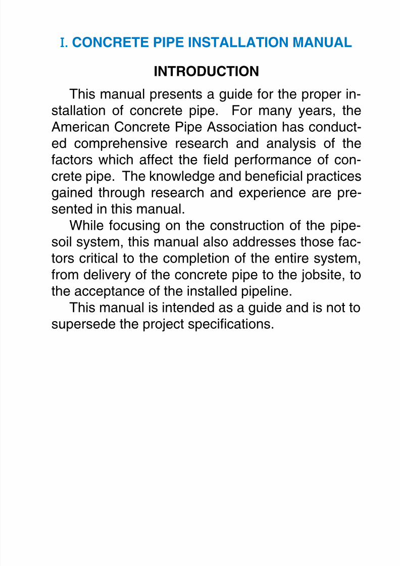
This manual presents a guide for the proper in-stallation of concrete pipe. For many years, theAmerican Concrete Pipe Association has conduct-ed comprehensive research and analysis of thefactors which affect the eld performance of con-crete pipe. The knowledge and benecial practices
gained through research and experience are pre-sented in this manual.While focusing on the construction of the pipe-
soil system, this manual also addresses those fac-tors critical to the completion of the entire system,from delivery of the concrete pipe to the jobsite, to
the acceptance of the installed pipeline.This manual is intended as a guide and is not tosupersede the project specications.

8/7/2019 Concrete Pipe - Installation Guide
http://slidepdf.com/reader/full/concrete-pipe-installation-guide 6/91
American Concrete Pipe Association • www.concrete-pipe.org
PRE-CONSTRUCTION
PRECAUTIONS
Federal regulations covering safety for all typesof construction, including sewer and culvert instal-lations, are published in the Safety and Health Reg-ulations for Construction under the Department ofLabor, Occupational Safety and Health Administra-tion (OSHA). These regulations are applicable to
all prime contractors and subcontractors involved inany type of construction, including alterations andrepair work.
The installer should also review installation prac-tices with the engineer’s design assumptions, par-ticularly in relation to the use of trench boxes and
compaction requirements of the backll.ORDERING,RECEIVINGANDHANDLING
Although the ordering of materials is the contrac-tor’s responsibility, supplier and engineer familiaritywith the contractor’s proposed schedule will en-able better coordination to avoid mistakes and pos-
sible delays in pipe deliveries. Pipe manufactur-ers stock a wide range of pipe sizes and strengths,but production facilities must frequently be adaptedto meet specic project requirements, particularlywhen large quantities and/or special types of pipeare involved. Information required to initiate a pipe
order should be in writing and include:name and location of projectpipe size, laying length and strengthtotal footage of each type and size of pipetype of jointsize and quantity of manhole base sections,
riser sections, cone sections and grade ringslist of ttings and specials including radius pipe
•••••
•
8/7/2019 Concrete Pipe - Installation Guide
http://slidepdf.com/reader/full/concrete-pipe-installation-guide 7/91
American Concrete Pipe Association • www.concrete-pipe.org
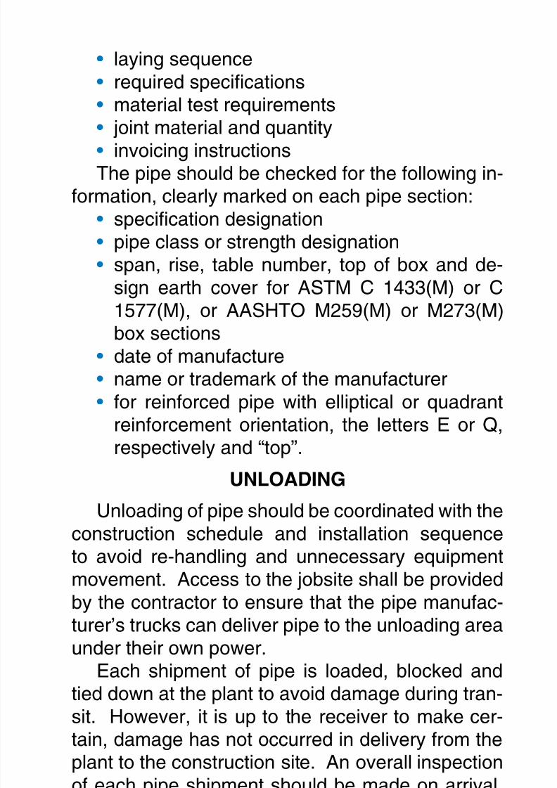
laying sequencerequired specicationsmaterial test requirements
joint material and quantityinvoicing instructionsThe pipe should be checked for the following in-
formation, clearly marked on each pipe section:specication designationpipe class or strength designationspan, rise, table number, top of box and de-sign earth cover for ASTM C 1433(M) or C1577(M), or AASHTO M259(M) or M273(M)box sectionsdate of manufacturename or trademark of the manufacturerfor reinforced pipe with elliptical or quadrantreinforcement orientation, the letters E or Q,respectively and “top”.
UNLOADING
Unloading of pipe should be coordinated with theconstruction schedule and installation sequence
to avoid re-handling and unnecessary equipmentmovement. Access to the jobsite shall be providedby the contractor to ensure that the pipe manufac-turer’s trucks can deliver pipe to the unloading areaunder their own power.
Each shipment of pipe is loaded, blocked and
tied down at the plant to avoid damage during tran-sit. However, it is up to the receiver to make cer-tain, damage has not occurred in delivery from theplant to the construction site. An overall inspectionof each pipe shipment should be made on arrival,before the pipe is unloaded. Total quantities of
each item should be checked against the deliveryslip and any damaged or missing items recorded on
•••
••
•••
•••
8/7/2019 Concrete Pipe - Installation Guide
http://slidepdf.com/reader/full/concrete-pipe-installation-guide 8/91
American Concrete Pipe Association • www.concrete-pipe.org
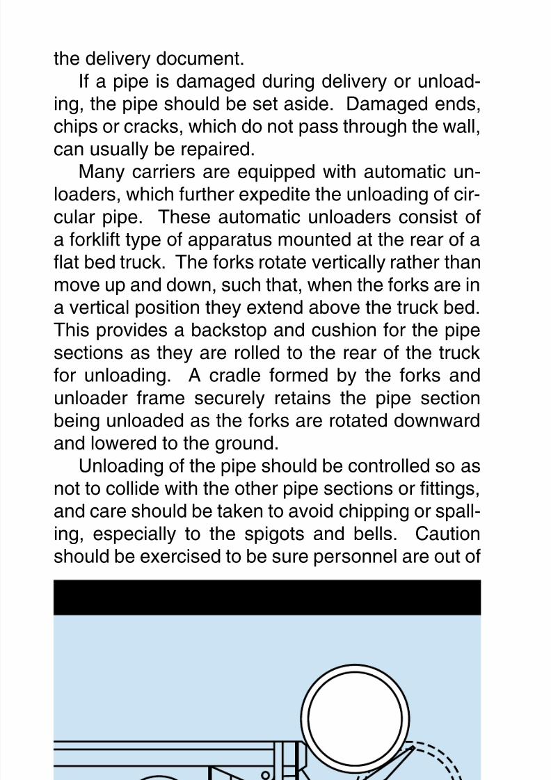
AUTOMATIC UNLOADER
the delivery document.If a pipe is damaged during delivery or unload-
ing, the pipe should be set aside. Damaged ends,
chips or cracks, which do not pass through the wall,can usually be repaired.Many carriers are equipped with automatic un-
loaders, which further expedite the unloading of cir-cular pipe. These automatic unloaders consist ofa forklift type of apparatus mounted at the rear of aat bed truck. The forks rotate vertically rather thanmove up and down, such that, when the forks are ina vertical position they extend above the truck bed.This provides a backstop and cushion for the pipesections as they are rolled to the rear of the truckfor unloading. A cradle formed by the forks andunloader frame securely retains the pipe sectionbeing unloaded as the forks are rotated downwardand lowered to the ground.
Unloading of the pipe should be controlled so asnot to collide with the other pipe sections or ttings,and care should be taken to avoid chipping or spall-ing, especially to the spigots and bells. Cautionshould be exercised to be sure personnel are out of
8/7/2019 Concrete Pipe - Installation Guide
http://slidepdf.com/reader/full/concrete-pipe-installation-guide 9/91
American Concrete Pipe Association • www.concrete-pipe.org
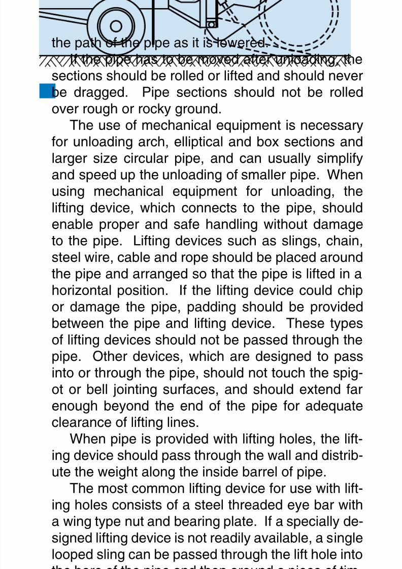
the path of the pipe as it is lowered.If the pipe has to be moved after unloading, the
sections should be rolled or lifted and should never
be dragged. Pipe sections should not be rolledover rough or rocky ground.The use of mechanical equipment is necessary
for unloading arch, elliptical and box sections andlarger size circular pipe, and can usually simplifyand speed up the unloading of smaller pipe. Whenusing mechanical equipment for unloading, thelifting device, which connects to the pipe, shouldenable proper and safe handling without damageto the pipe. Lifting devices such as slings, chain,steel wire, cable and rope should be placed aroundthe pipe and arranged so that the pipe is lifted in ahorizontal position. If the lifting device could chipor damage the pipe, padding should be providedbetween the pipe and lifting device. These typesof lifting devices should not be passed through thepipe. Other devices, which are designed to passinto or through the pipe, should not touch the spig-ot or bell jointing surfaces, and should extend farenough beyond the end of the pipe for adequateclearance of lifting lines.
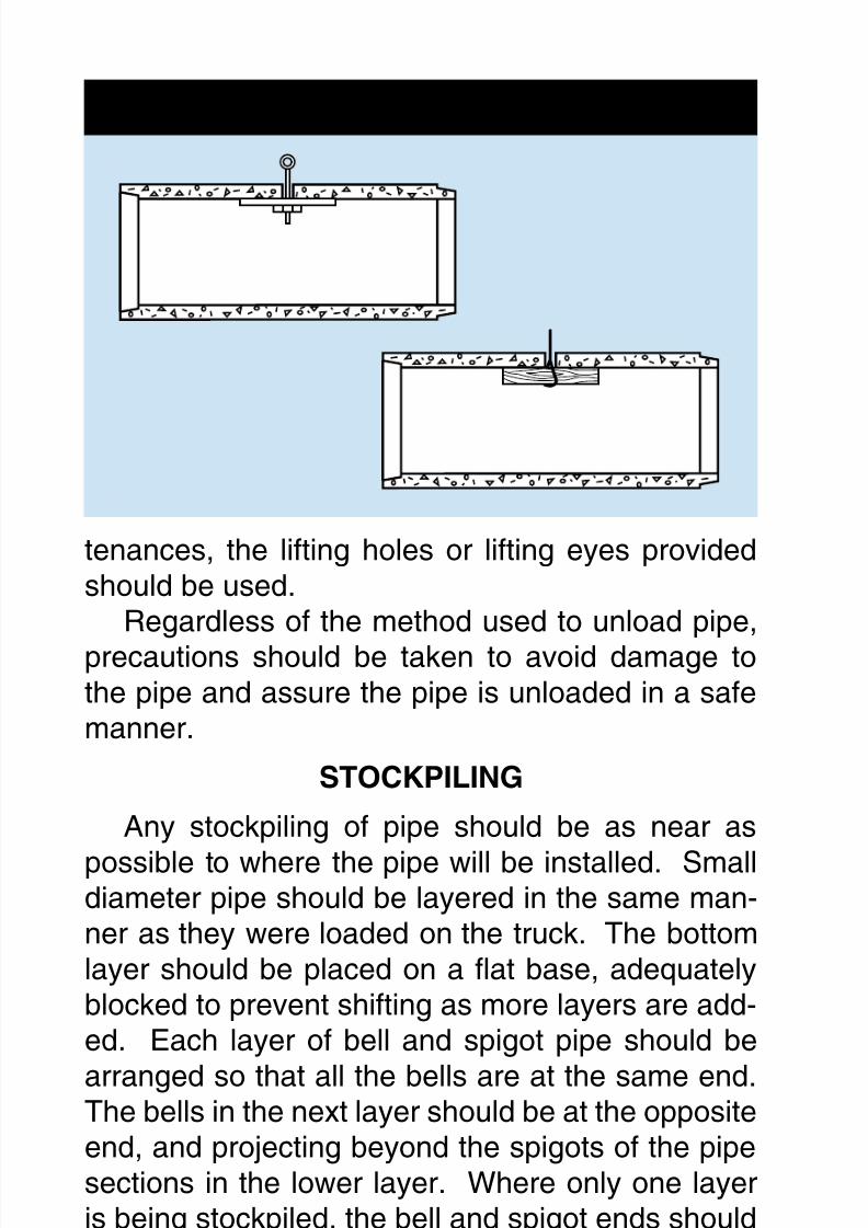
When pipe is provided with lifting holes, the lift-ing device should pass through the wall and distrib-ute the weight along the inside barrel of pipe.
The most common lifting device for use with lift-ing holes consists of a steel threaded eye bar witha wing type nut and bearing plate. If a specially de-signed lifting device is not readily available, a singlelooped sling can be passed through the lift hole intothe bore of the pipe and then around a piece of tim-ber of adequate length and cross-section to assurestructural stability. For manhole sections, conesections, bases, ttings and other precast appur-
8/7/2019 Concrete Pipe - Installation Guide
http://slidepdf.com/reader/full/concrete-pipe-installation-guide 10/91
American Concrete Pipe Association • www.concrete-pipe.org10
LIFT HOLD DEVICES
tenances, the lifting holes or lifting eyes providedshould be used.
Regardless of the method used to unload pipe,
precautions should be taken to avoid damage tothe pipe and assure the pipe is unloaded in a safemanner.
STOCKPILING
Any stockpiling of pipe should be as near as
possible to where the pipe will be installed. Smalldiameter pipe should be layered in the same man-ner as they were loaded on the truck. The bottomlayer should be placed on a at base, adequatelyblocked to prevent shifting as more layers are add-ed. Each layer of bell and spigot pipe should be
arranged so that all the bells are at the same end.The bells in the next layer should be at the oppositeend, and projecting beyond the spigots of the pipesections in the lower layer. Where only one layeris being stockpiled, the bell and spigot ends shouldalternate between the adjacent pipe sections. All
pipes should be supported by the pipe barrel sothat the joint ends are free of load concentrations.Pipe sections generally should not be stockpiled at
8/7/2019 Concrete Pipe - Installation Guide
http://slidepdf.com/reader/full/concrete-pipe-installation-guide 11/91
American Concrete Pipe Association • www.concrete-pipe.org 11
the job site in a greater number of layers than wouldresult in a height of 6 ft. (2 m).
All exible gasket materials not cemented to
the pipe, including joint lubrication compounds,should be stored in a cool dry place to be distrib-uted as needed. Rubber gaskets and preformed orbulk mastics should be kept clean, away from oil,grease, and excessive heat and out of the directrays of the sun.
8/7/2019 Concrete Pipe - Installation Guide
http://slidepdf.com/reader/full/concrete-pipe-installation-guide 12/91
American Concrete Pipe Association • www.concrete-pipe.org1
INSTALLATION
LINEANDGRADE
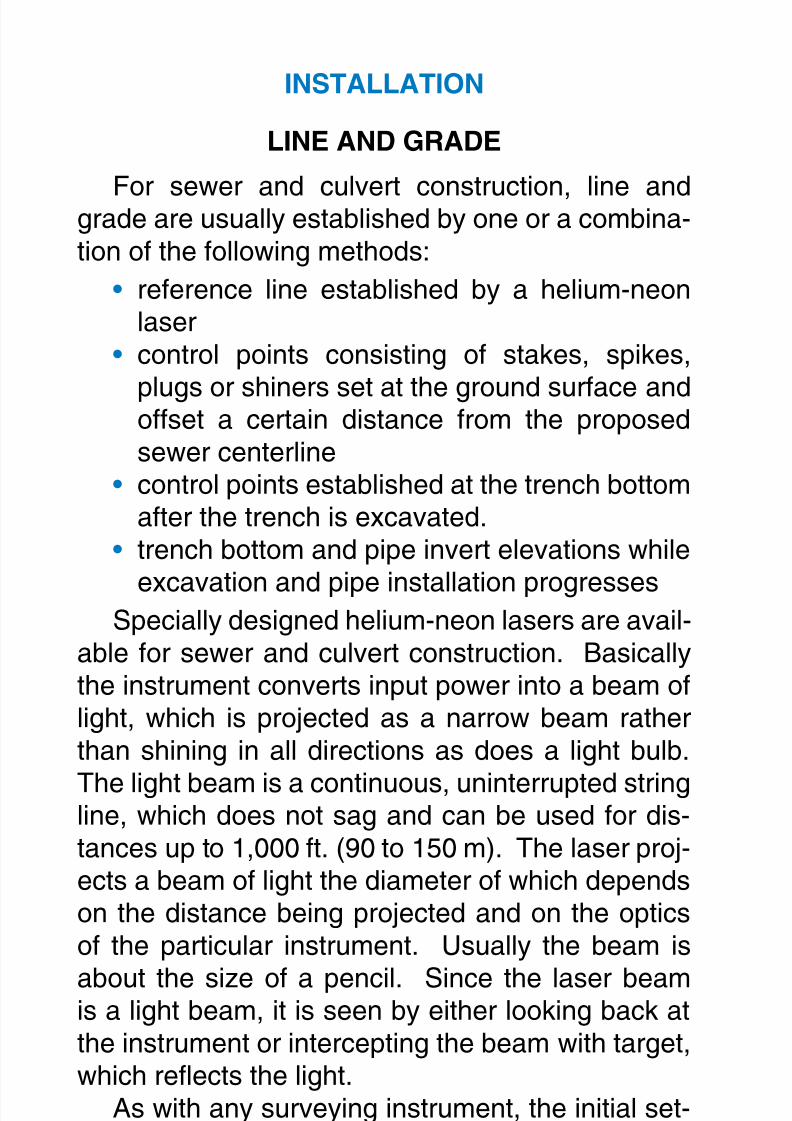
For sewer and culvert construction, line andgrade are usually established by one or a combina-tion of the following methods:
reference line established by a helium-neonlasercontrol points consisting of stakes, spikes,
plugs or shiners set at the ground surface andoffset a certain distance from the proposedsewer centerlinecontrol points established at the trench bottomafter the trench is excavated.trench bottom and pipe invert elevations while
excavation and pipe installation progressesSpecially designed helium-neon lasers are avail-
able for sewer and culvert construction. Basicallythe instrument converts input power into a beam oflight, which is projected as a narrow beam ratherthan shining in all directions as does a light bulb.
The light beam is a continuous, uninterrupted stringline, which does not sag and can be used for dis-tances up to 1,000 ft. (90 to 150 m). The laser proj-ects a beam of light the diameter of which dependson the distance being projected and on the opticsof the particular instrument. Usually the beam is
about the size of a pencil. Since the laser beamis a light beam, it is seen by either looking back atthe instrument or intercepting the beam with target,which reects the light.
As with any surveying instrument, the initial set-ting is most important. But once a laser is set as
to direction and grade, it provides a constant refer-ence line from which measurements can be takenat any point along the beam. A workman with any
•
•
•
•
8/7/2019 Concrete Pipe - Installation Guide
http://slidepdf.com/reader/full/concrete-pipe-installation-guide 13/91
American Concrete Pipe Association • www.concrete-pipe.org 1
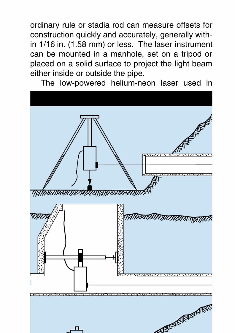
ordinary rule or stadia rod can measure offsets forconstruction quickly and accurately, generally with-in 1/16 in. (1.58 mm) or less. The laser instrument
can be mounted in a manhole, set on a tripod orplaced on a solid surface to project the light beameither inside or outside the pipe.
The low-powered helium-neon laser used in
LASER SYSTEM
8/7/2019 Concrete Pipe - Installation Guide
http://slidepdf.com/reader/full/concrete-pipe-installation-guide 14/91
American Concrete Pipe Association • www.concrete-pipe.org1
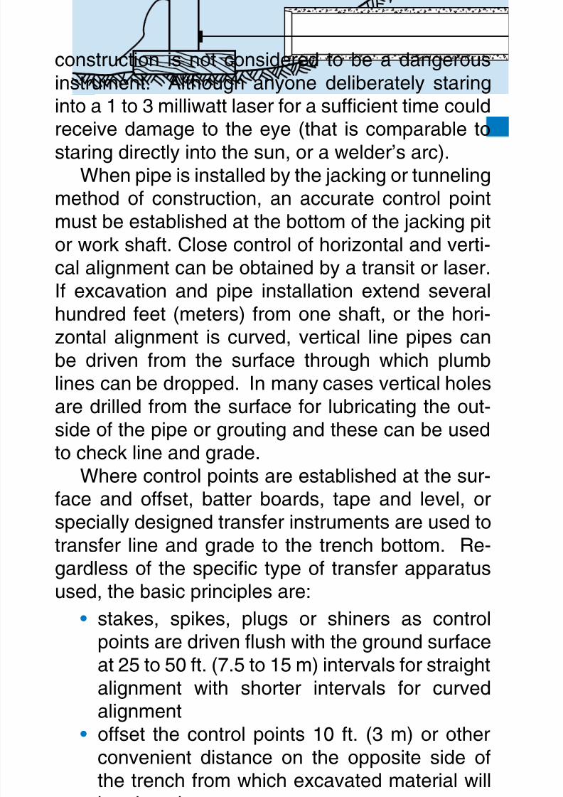
construction is not considered to be a dangerousinstrument. Although anyone deliberately staringinto a 1 to 3 milliwatt laser for a sufcient time could
receive damage to the eye (that is comparable tostaring directly into the sun, or a welder’s arc).When pipe is installed by the jacking or tunneling
method of construction, an accurate control pointmust be established at the bottom of the jacking pitor work shaft. Close control of horizontal and verti-cal alignment can be obtained by a transit or laser.If excavation and pipe installation extend severalhundred feet (meters) from one shaft, or the hori-zontal alignment is curved, vertical line pipes canbe driven from the surface through which plumblines can be dropped. In many cases vertical holesare drilled from the surface for lubricating the out-side of the pipe or grouting and these can be usedto check line and grade.
Where control points are established at the sur-face and offset, batter boards, tape and level, orspecially designed transfer instruments are used totransfer line and grade to the trench bottom. Re-gardless of the specic type of transfer apparatusused, the basic principles are:
stakes, spikes, plugs or shiners as controlpoints are driven ush with the ground surfaceat 25 to 50 ft. (7.5 to 15 m) intervals for straight
alignment with shorter intervals for curvedalignmentoffset the control points 10 ft. (3 m) or otherconvenient distance on the opposite side ofthe trench from which excavated material willbe placeddetermine control point elevations by meansof a level, transit or other leveling device andindicate on the guard stake driven next to the
•
•
•
8/7/2019 Concrete Pipe - Installation Guide
http://slidepdf.com/reader/full/concrete-pipe-installation-guide 15/91
American Concrete Pipe Association • www.concrete-pipe.org 1
control point the depth from the control point tothe trench bottom or pipe invertby means of longer grade stakes, driven im-
mediately adjacent to the control points, a con-tinuous string line is tied to the grade stakes ata specic distance above the trench bottom orpipe invertafter the surface control points are set, a cutsheet is prepared listing reference points, sta-tioning, offset distance and vertical distancefrom the control points to the trench bottom orpipe invert
For narrow trenches a horizontal batter boardis spanned across the trench and adequately sup-ported at each end. The batter board is set level
at the same elevation as the string line and a naildriven in the upper edge at the centerline of thepipe. In many cases the batter board is used onlyas a spanning member with a short vertical boardnailed to it at the pipe centerline. A string line isthen pulled tight across a minimum of three batter
boards and line transferred to the trench bottomby a plumb bob cord held against the string line.Grade is transferred to the trench bottom by meansof a grade rod or other suitable vertical measuringdevice.
Where wide trenches are necessary, due to
large pipe sizes or sloped trench walls, the batterboard may not be able the span the width of exca-vation. In such cases, the same transfer principle isused, except that the vertical grade rod is attachedto one end of the batter board and the other end setlevel against the offset string line. The length of the
horizontal batter board is the same as the offset dis-tance and the length of the vertical grade rod is thesame distance between the trench bottom or pipe
•
•

8/7/2019 Concrete Pipe - Installation Guide
http://slidepdf.com/reader/full/concrete-pipe-installation-guide 16/91
American Concrete Pipe Association • www.concrete-pipe.org1
invert and the string line. Specially designed instru-ments are available which incorporate a measuringtape, extendable arm and leveling device. These
instruments are based on the same principle, buteliminate the need to construct batter boards andsupports and are portable.
The transfer of surface control points to stakesalong the trench bottom is sometimes necessarybecause of the deep trenches or unstable soils re-quiring the trench sides to be sloped back. Stakesshould be set along the trench bottom at 50 ft. (15m) intervals and a string line drawn between two
EXAMPLE BATTER BOARD SET-UP
GradeStake
Grade Rod RegisteringGrade of Invert
BatterBoard
Grade
String
Grade Rod RegisteringGrade of Trench
8/7/2019 Concrete Pipe - Installation Guide
http://slidepdf.com/reader/full/concrete-pipe-installation-guide 17/91
American Concrete Pipe Association • www.concrete-pipe.org 1
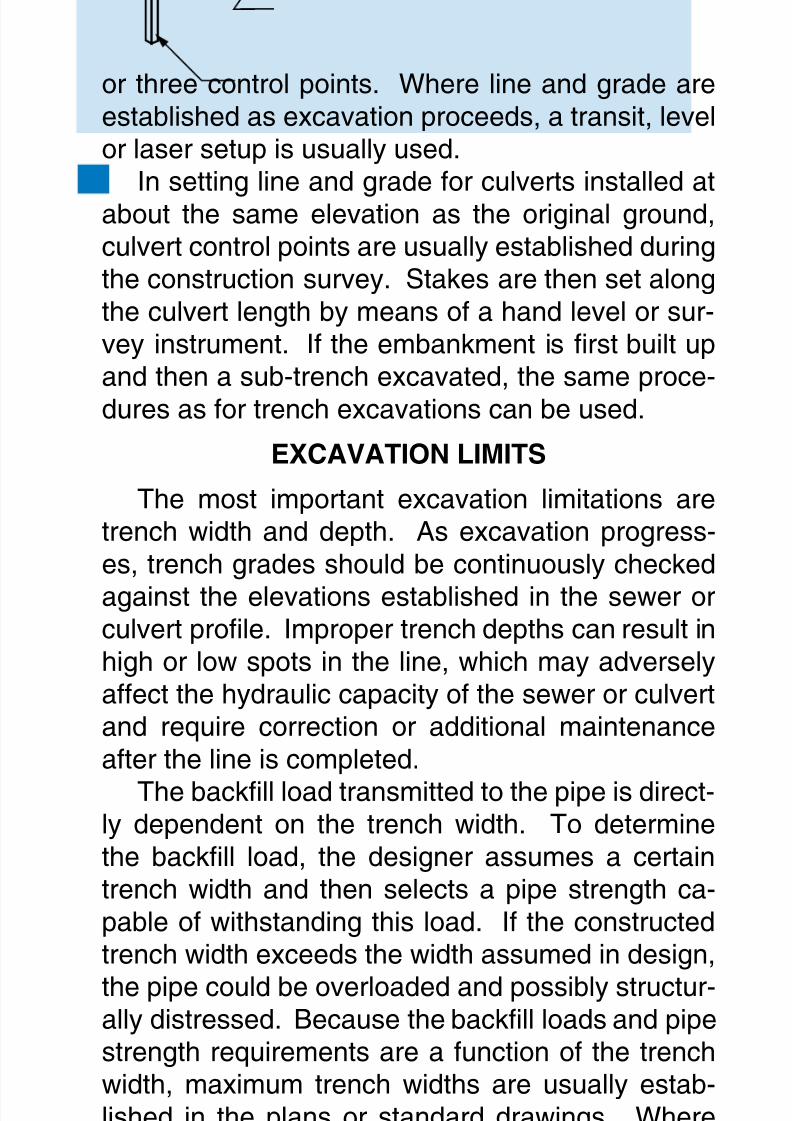
or three control points. Where line and grade areestablished as excavation proceeds, a transit, levelor laser setup is usually used.
In setting line and grade for culverts installed atabout the same elevation as the original ground,culvert control points are usually established duringthe construction survey. Stakes are then set alongthe culvert length by means of a hand level or sur-vey instrument. If the embankment is rst built upand then a sub-trench excavated, the same proce-dures as for trench excavations can be used.
EXCAVATIONLIMITS
The most important excavation limitations aretrench width and depth. As excavation progress-es, trench grades should be continuously checked
against the elevations established in the sewer orculvert prole. Improper trench depths can result inhigh or low spots in the line, which may adverselyaffect the hydraulic capacity of the sewer or culvertand require correction or additional maintenanceafter the line is completed.
The backll load transmitted to the pipe is direct-ly dependent on the trench width. To determinethe backll load, the designer assumes a certaintrench width and then selects a pipe strength ca-pable of withstanding this load. If the constructedtrench width exceeds the width assumed in design,
the pipe could be overloaded and possibly structur-ally distressed. Because the backll loads and pipestrength requirements are a function of the trenchwidth, maximum trench widths are usually estab-lished in the plans or standard drawings. Wheremaximum trench widths are not indicated in any of
the construction contract documents, trench widthsshould be as narrow as possible, with side clear-
8/7/2019 Concrete Pipe - Installation Guide
http://slidepdf.com/reader/full/concrete-pipe-installation-guide 18/91
American Concrete Pipe Association • www.concrete-pipe.org1
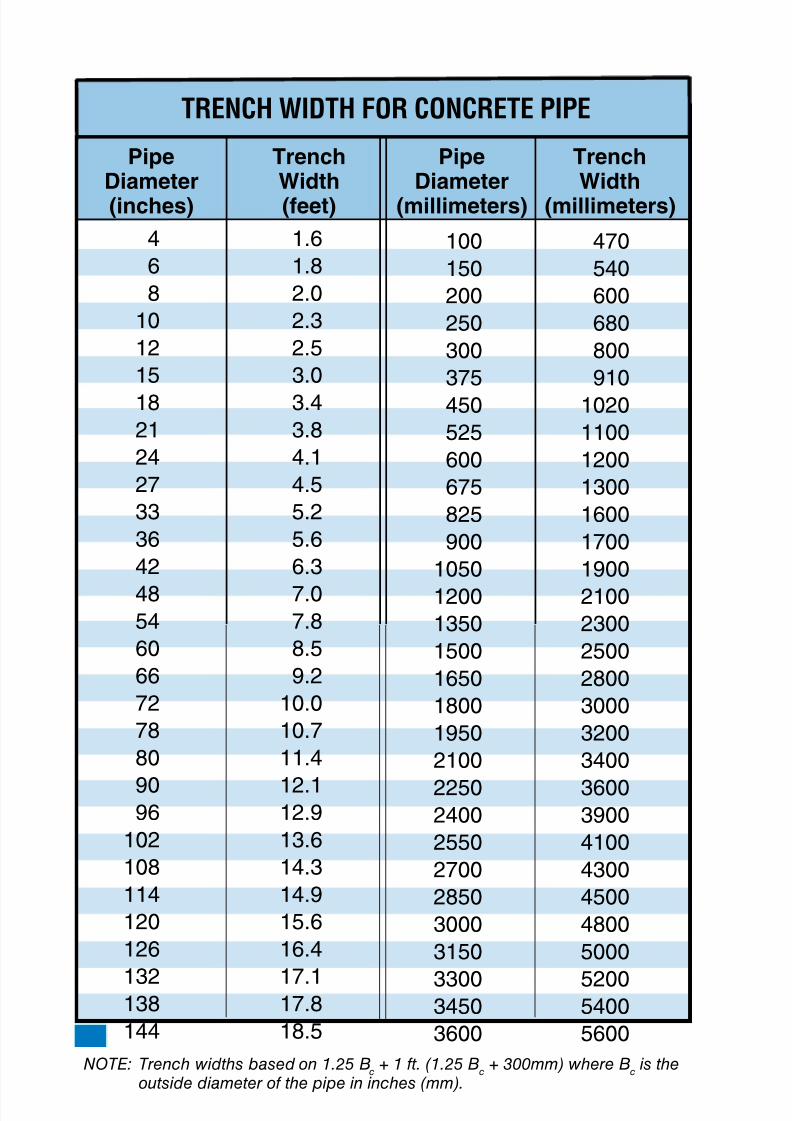
TRENCH WIDTH FOR CONCRETE PIPE
Pipe Trench Pipe TrenchDiameter Width Diameter Width(inches) (feet) (millimeters) (millimeters)
4 1.6
6 1.8
8 2.0
10 2.3
12 2.5
15 3.0
18 3.4
21 3.8
24 4.1
27 4.5
33 5.2
36 5.6
42 6.3
48 7.0
54 7.8
60 8.5
66 9.2
72 10.0
78 10.7
80 11.4
90 12.196 12.9
102 13.6
108 14.3
114 14.9
120 15.6
126 16.4
132 17.1138 17.8
144 18.5
100 470
150 540
200 600
250 680
300 800
375 910
450 1020
525 1100
600 1200
675 1300
825 1600
900 1700
1050 1900
1200 2100
1350 2300
1500 2500
1650 2800
1800 3000
1950 3200
2100 3400
2250 3600
2400 3900
2550 4100
2700 4300
2850 4500
3000 4800
3150 5000
3300 52003450 5400
3600 5600
NOTE: Trench widths based on 1.25 Bc
+ 1 ft. (1.25 Bc
+ 300mm) where Bc
is theoutside diameter of the pipe in inches (mm).
8/7/2019 Concrete Pipe - Installation Guide
http://slidepdf.com/reader/full/concrete-pipe-installation-guide 19/91
American Concrete Pipe Association • www.concrete-pipe.org 1
ance adequate enough to insure proper compac-tion of backll material at the sides of the pipe. Thefollowing trench widths can be used as a general
guide for circular concrete pipe:EXCAVATEDMATERIAL
If excavated material is to be stored on top of thepipeline, special consideration should be given tosurcharge loading during the design of the pipe.
Stockpiling excavated material adjacent to the
trench causes a surcharge load, which may cave inthe trench walls. The ability of the trench walls tostand vertically under this additional load dependson the cohesive characteristics of the particular typeof material being excavated. This surcharge loadshould be considered when evaluating the need to
provide trench support. It may be necessary wheredeep or wide trenches are being excavated to haulaway a portion of the excavated soil or spread thestockpile with a bulldozer or other equipment. Ifthe excavated material is to be used as backll, thestockpiled material should be visually inspected
for rocks, frozen lumps, highly plastic clay or otherobjectionable material. If the excavated soil differssignicantly from the intended backll material setforth in the plans, it may be necessary to haul theunsuitable soil away and bring in select backll ma-terial.
DEWATERING
Control of surface and subsurface water is re-quired so that dry conditions will be provided dur-ing excavation and pipe laying. Ground waterconditions should be investigated before they are
encountered during the course of excavation.
8/7/2019 Concrete Pipe - Installation Guide
http://slidepdf.com/reader/full/concrete-pipe-installation-guide 20/91
American Concrete Pipe Association • www.concrete-pipe.org0
STANDARDINSTALLATIONS
Through consultations with contractors and engi-neers, four Standard Installations were developed
and are presented in the following pages. The fol-lowing ideas, formulated from past experience, wereconrmed with parameter studies. These StandardInstallations represent an improved understand-ing of the installation factors effecting pipe perfor-mance and reect modern construction techniques.
They are designed to improve pipe performance byemphasizing benecial construction and installa-tion requirements. By providing installations, whichutilize a wide range of backll materials, includingnative materials, the Standard Installations offer theowner, engineer, and contractor more versatility in
selecting the installation to meet their unique com-bination of site conditions, backll materials and de-sired construction and inspection materials. Someof the ideas included in the Standard Installationsconrm the following concepts:
The soil in the haunch area from the foundation
to the pipe springline provides signicant sup-port to the pipe and reduces pipe stresses.Loosely placed, uncompacted bedding directlyunder the invert of the pipe signicantly reduc-es stresses in the pipe.Installation materials and compaction levels
below the springline have a signicant effecton pipe structural requirements.Soil in those portions of the bedding andhaunch areas directly under the pipe is difcultto compact.Compaction level of the soil directly above the
haunch, from the pipe springline to the topof the pipe grade level, has negligible effect
•
•
•
•
•
8/7/2019 Concrete Pipe - Installation Guide
http://slidepdf.com/reader/full/concrete-pipe-installation-guide 21/91
American Concrete Pipe Association • www.concrete-pipe.org 1
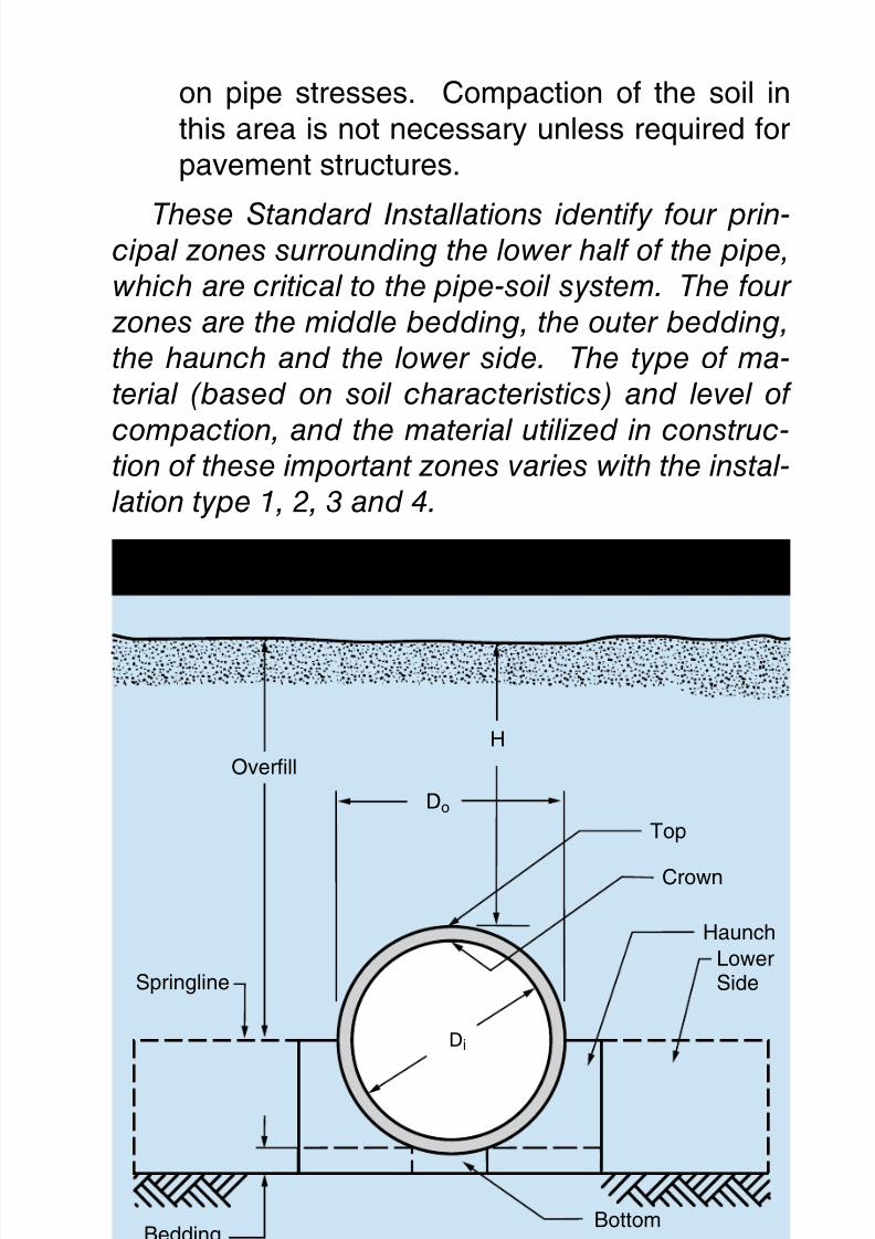
on pipe stresses. Compaction of the soil inthis area is not necessary unless required forpavement structures.
These Standard Installations identify four prin-cipal zones surrounding the lower half of the pipe,which are critical to the pipe-soil system. The four
zones are the middle bedding, the outer bedding,the haunch and the lower side. The type of ma-terial (based on soil characteristics) and level of
compaction, and the material utilized in construc-tion of these important zones varies with the instal-lation type 1, 2, 3 and 4.
PIPE/INSTALLATIONTERMINOLOGY
Do
Di
Bottom
Crown
Foundation
(Existing Soil or Compacted Fill)
Bedding
Springline
H
Haunch
Top
LowerSide
Overfill

8/7/2019 Concrete Pipe - Installation Guide
http://slidepdf.com/reader/full/concrete-pipe-installation-guide 22/91
American Concrete Pipe Association • www.concrete-pipe.org
Do
Do/6 (Min.)Do (Min.)
Do/3
Di
Middle bedding looselyplaced uncompactedbedding except Type 4
Outer bedding materials andcompaction each side, same
requirements as haunch
Foundation
BeddingSee Tables 1 & 2
H
Haunch
Lower SideSpringline
Overfill Soil
Category I, II, III
STANDARDTRENCH/EMBANKMENTINSTALLATION
SIDD Standard ModifiedSoil USCS AASHTO Proctor Proctor
Representative Soil Types Percent Compaction
Gravellysand
(Category I)
SandySilt
(Category II)
SiltyClay
(Category III)
SW, SPGW, GP
GM, SM, MLAlso GC, SC
with less than20% passing#200 sieve
CL, MHGC, SC
A1, A3
A2, A4
A5, A6
1009590858061
1009590858049
10095
90858045
EQUIVALENT USCS AND AASHTO SOILCLASSIFICATIONS FOR SIDD SOIL DESIGNATIONS
959085807559
959085807546
9085
80757040
8/7/2019 Concrete Pipe - Installation Guide
http://slidepdf.com/reader/full/concrete-pipe-installation-guide 23/91
American Concrete Pipe Association • www.concrete-pipe.org 23
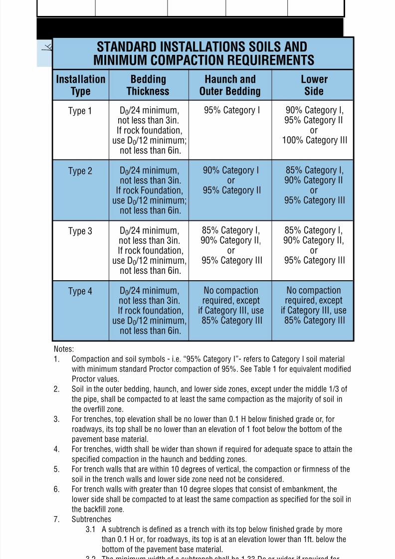
Installation Bedding Haunch and LowerType Thickness Outer Bedding Side
Type 1
Type 2
Type 3
Type 4
D0/24 minimum,not less than 3in.If rock foundation,
use D0/12 minimum;not less than 6in.
D0/24 minimum,not less than 3in.
If rock Foundation,use D0/12 minimum;
not less than 6in.
D0/24 minimum,not less than 3in.If rock foundation,
use D0/12 minimum,not less than 6in.
D0/24 minimum,not less than 3in.If rock foundation,
use D0/12 minimum,not less than 6in.
95% Category I
90% Category Ior
95% Category II
85% Category I,90% Category II,
or95% Category III
No compactionrequired, exceptif Category III, use85% Category III
90% Category I,95% Category II
or100% Category III
85% Category I,90% Category II
or95% Category III
85% Category I,90% Category II,
or95% Category III
No compactionrequired, exceptif Category III, use85% Category III
STANDARD INSTALLATIONS SOILS ANDMINIMUM COMPACTION REQUIREMENTS
Notes:
1. Compaction and soil symbols - i.e. “95% Category I”- refers to Category I soil material
with minimum standard Proctor compaction of 95%. See Table 1 for equivalent modified
Proctor values.
2. Soil in the outer bedding, haunch, and lower side zones, except under the middle 1/3 ofthe pipe, shall be compacted to at least the same compaction as the majority of soil in
the overfill zone.
3. For trenches, top elevation shall be no lower than 0.1 H below finished grade or, for
roadways, its top shall be no lower than an elevation of 1 foot below the bottom of the
pavement base material.
4. For trenches, width shall be wider than shown if required for adequate space to attain the
specified compaction in the haunch and bedding zones.
5. For trench walls that are within 10 degrees of vertical, the compaction or firmness of the
soil in the trench walls and lower side zone need not be considered.
6. For trench walls with greater than 10 degree slopes that consist of embankment, thelower side shall be compacted to at least the same compaction as specified for the soil in
the backfill zone.
7. Subtrenches
3.1 A subtrench is defined as a trench with its top below finished grade by more
than 0.1 H or, for roadways, its top is at an elevation lower than 1ft. below the
bottom of the pavement base material.
3.2 The minimum width of a subtrench shall be 1.33 Do or wider if required for
adequate space to attain the specified compaction in the haunch and bedding
zones.
3.3 For subtrenches with walls of natural soil, any portion of the lower side zone inthe subtrench wall shall be at least as firm as an equivalent soil placed to the
compaction requirements specified for the lower side zone and as firm as the
majority of soil in the overfill zone, or shall be removed and replaced with soil
compacted to the specified level.
8/7/2019 Concrete Pipe - Installation Guide
http://slidepdf.com/reader/full/concrete-pipe-installation-guide 24/91
American Concrete Pipe Association • www.concrete-pipe.org
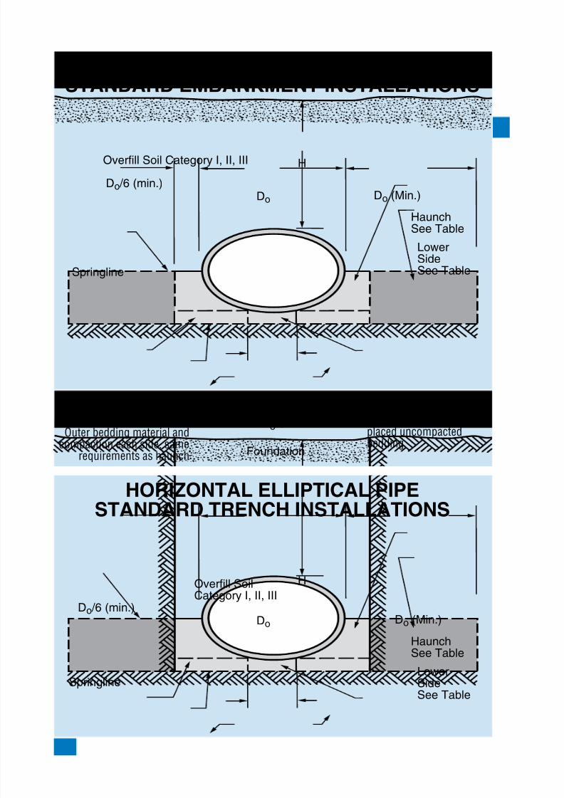
HORIZONTALELLIPTICALPIPESTANDARDEMBANKMENTINSTALLATIONS
HORIZONTALELLIPTICALPIPESTANDARDTRENCHINSTALLATIONS
Do
Do/6 (min.)Do (Min.)
Do/3 Middle Bedding looselyplaced uncompactedbedding
Foundation
Springline
H
HaunchSee Table
LowerSideSee Table
Overfill Soil Category I, II, III
Outer bedding material andcompaction each side, same
requirements as haunch
Bedding See Table
Overfill SoilCategory I, II, III
Do
Do/6 (min.)Do (Min.)
Do/3 Middle Bedding looselyplaced uncompactedbedding
Foundation
Springline
H
HaunchSee Table
LowerSide
See Table
Outer bedding material andcompaction each side, same
requirements as haunch
Bedding See Table
8/7/2019 Concrete Pipe - Installation Guide
http://slidepdf.com/reader/full/concrete-pipe-installation-guide 25/91
American Concrete Pipe Association • www.concrete-pipe.org
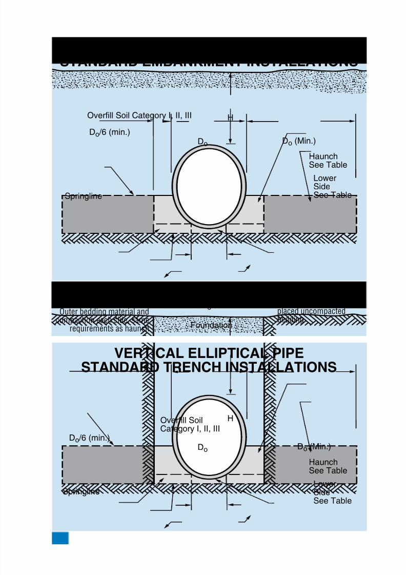
VERTICALELLIPTICALPIPESTANDARDEMBANKMENTINSTALLATIONS
VERTICALELLIPTICALPIPESTANDARDTRENCHINSTALLATIONS
Do
Do/6 (min.)Do (Min.)
Do/3 Middle Bedding looselyplaced uncompactedbedding
Foundation
Springline
H
HaunchSee Table
LowerSideSee Table
Overfill Soil Category I, II, III
Outer bedding material andcompaction each side, same
requirements as haunch
Bedding See Table
Overfill SoilCategory I, II, III
Do
Do/6 (min.)Do (Min.)
Do/3 Middle Bedding looselyplaced uncompactedbedding
Foundation
Springline
H
HaunchSee Table
LowerSide
See Table
Outer bedding material andcompaction each side, same
requirements as haunch
Bedding See Table
8/7/2019 Concrete Pipe - Installation Guide
http://slidepdf.com/reader/full/concrete-pipe-installation-guide 26/91
American Concrete Pipe Association • www.concrete-pipe.org
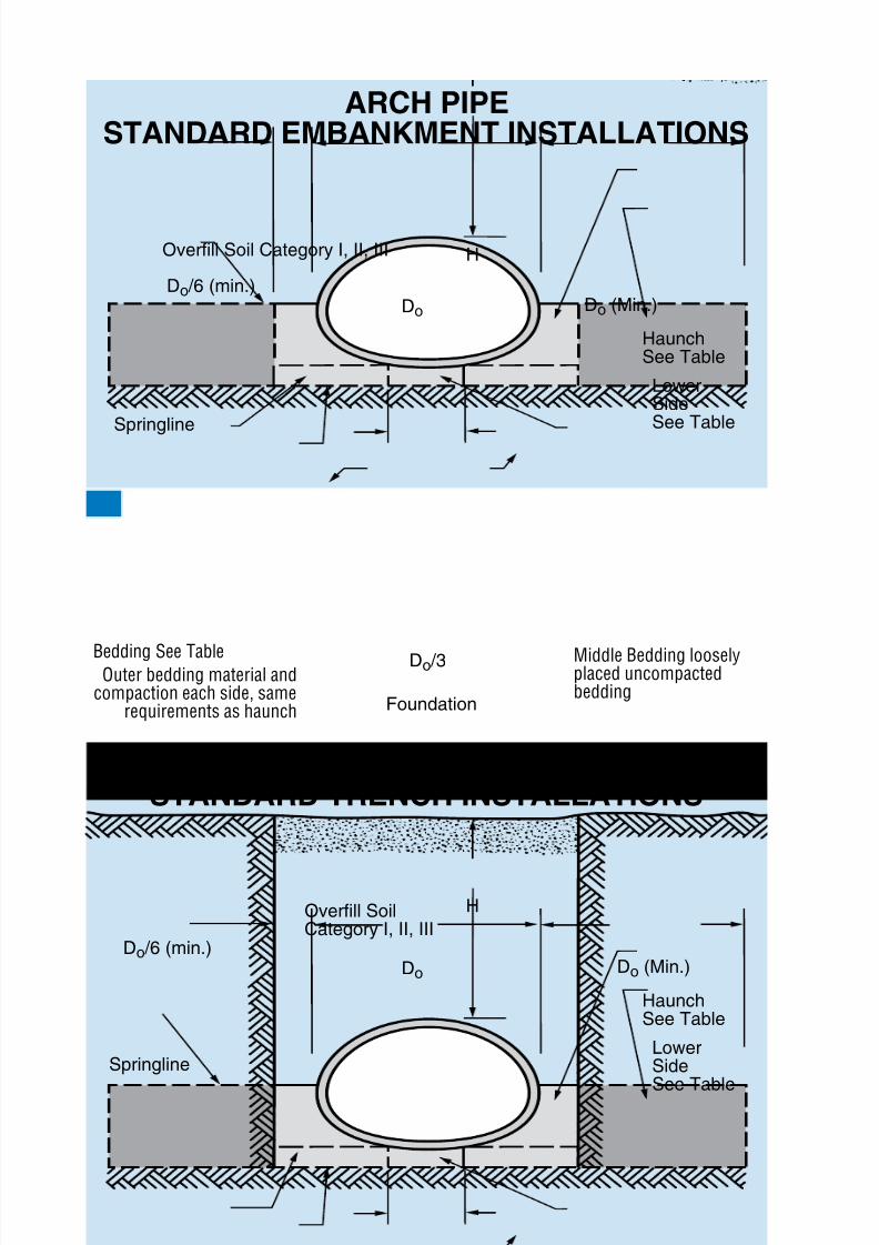
ARCHPIPESTANDARDEMBANKMENTINSTALLATIONS
ARCHPIPESTANDARDTRENCHINSTALLATIONS
Do
Do/6 (min.)Do (Min.)
Do/3 Middle Bedding looselyplaced uncompactedbedding
Foundation
Springline
H
HaunchSee Table
LowerSideSee Table
Overfill Soil Category I, II, III
Outer bedding material andcompaction each side, same
requirements as haunch
Bedding See Table
Overfill SoilCategory I, II, III
Do
Do/6 (min.)Do (Min.)
Do/3 Middle Bedding looselyplaced uncompactedbedding
Foundation
Springline
H
HaunchSee Table
LowerSide
See Table
Outer bedding material andcompaction each side, same
requirements as haunch
Bedding See Table
8/7/2019 Concrete Pipe - Installation Guide
http://slidepdf.com/reader/full/concrete-pipe-installation-guide 27/91
American Concrete Pipe Association • www.concrete-pipe.org
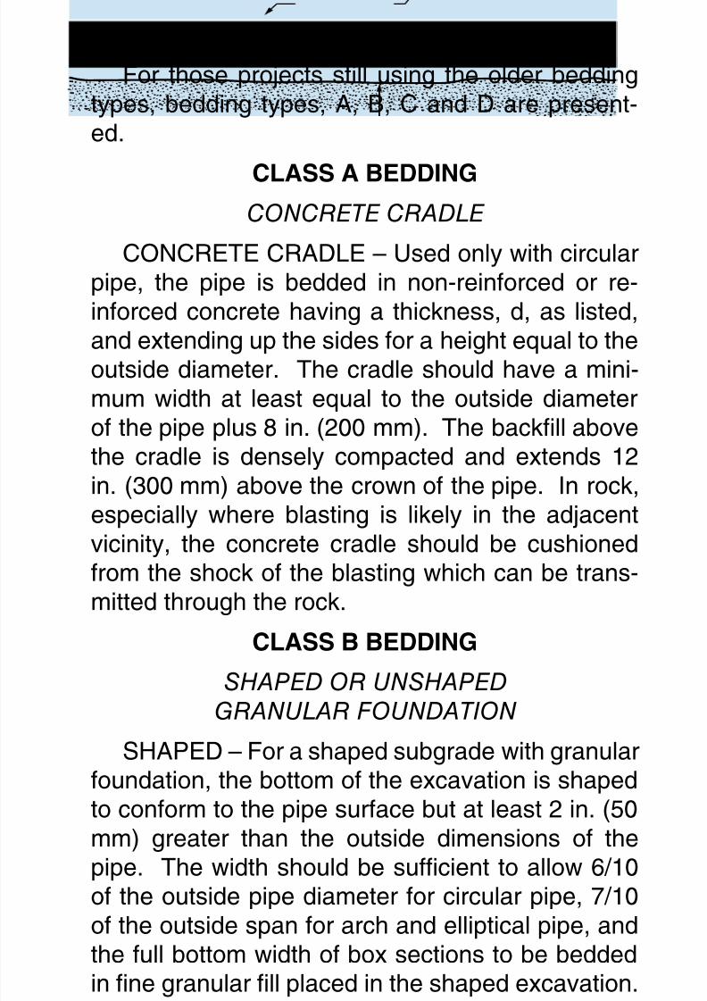
For those projects still using the older beddingtypes, bedding types, A, B, C and D are present-ed.
CLASSABEDDINGCONCRETE CRADLE
CONCRETE CRADLE – Used only with circularpipe, the pipe is bedded in non-reinforced or re-inforced concrete having a thickness, d, as listed,
and extending up the sides for a height equal to theoutside diameter. The cradle should have a mini-mum width at least equal to the outside diameterof the pipe plus 8 in. (200 mm). The backll abovethe cradle is densely compacted and extends 12in. (300 mm) above the crown of the pipe. In rock,
especially where blasting is likely in the adjacentvicinity, the concrete cradle should be cushionedfrom the shock of the blasting which can be trans-mitted through the rock.
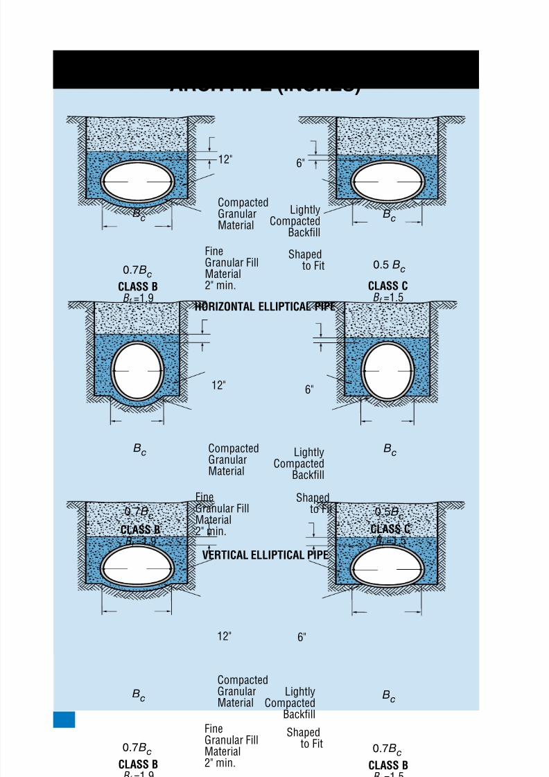
CLASSBBEDDING
SHAPED OR UNSHAPED
GRANULAR FOUNDATION
SHAPED – For a shaped subgrade with granularfoundation, the bottom of the excavation is shapedto conform to the pipe surface but at least 2 in. (50mm) greater than the outside dimensions of the
pipe. The width should be sufcient to allow 6/10of the outside pipe diameter for circular pipe, 7/10of the outside span for arch and elliptical pipe, andthe full bottom width of box sections to be beddedin ne granular ll placed in the shaped excavation.Densely compacted backll should be placed at the
sides of the pipe to a depth of at least 12 in. (300mm) above the top of the pipe.

8/7/2019 Concrete Pipe - Installation Guide
http://slidepdf.com/reader/full/concrete-pipe-installation-guide 28/91
American Concrete Pipe Association • www.concrete-pipe.org
UNSHAPED – A granular foundation withoutshaping is used only with circular pipe. The pipe isbedded in compacted granular material placed on
the at trench bottom. The granular bedding hasa minimum thickness, d, as listed and should ex-tend at least halfway at the sides. The remainderof the side lls, and a minimum depth of 12 in. (300mm) over the top of the pipe, should be lled withdensely compacted material.
CLASSCBEDDINGSHAPED SUBGRADE OR
GRANULAR FOUNDATION
SHAPED SUBGRADE – The pipe is beddedwith ordinary care in a soil foundation, shaped to t
the lower part of the pipe exterior with reasonablecloseness for a width of at least 50 percent of theoutside diameter for a circular pipe, and 1/10 of theoutside pipe rise for arch pipe, elliptical pipe andbox sections. For trench installations the sides andarea over the pipe are lled with lightly compacted
backll to a minimum depth of 6 in. (150 mm) abovethe top of the pipe. For embankment installationsthe pipe should not project more than 90 percent ofthe vertical height of the pipe above the bedding.
GRANULAR FOUNDATION – Used only withcircular pipe, the pipe is bedded in compactedgranular material or densely compacted backllplaced on a at bottom trench. The bedding mate-rial should have a minimum thickness as indicatedand should extend up the sides for a height of atleast 1/6 the outside diameter. For trench instal-lations the sidell and area over the pipe to a mini-mum depth of 6 in. (150 mm) should be lled withlightly compacted backll.

8/7/2019 Concrete Pipe - Installation Guide
http://slidepdf.com/reader/full/concrete-pipe-installation-guide 29/91
American Concrete Pipe Association • www.concrete-pipe.org
CLASSDBEDDING
Used only with circular pipe, little or no care isexercised either to shape the foundation surface to
t the lower part of the pipe exterior, or to ll allspaces under and around the pipe with granularmaterials. However, the gradient of the bed shouldbe smooth and true to established grade. Thisclass of bedding also includes the case of pipe onrock foundations in which an earth cushion is pro-
vided under the pipe but is so shallow that the pipe,as it settles under the inuence of vertical load, ap-proaches contact with the rock.
8/7/2019 Concrete Pipe - Installation Guide
http://slidepdf.com/reader/full/concrete-pipe-installation-guide 30/91
American Concrete Pipe Association • www.concrete-pipe.org0
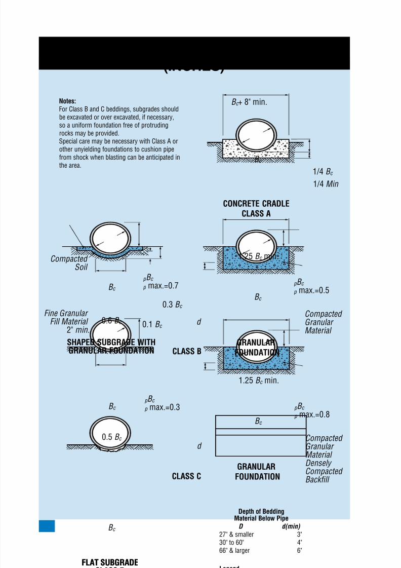
EMBANKMENTBEDDINGCIRCULARPIPE(INCHES)
B c
FLAT SUBGRADECLASS D
B c
0.6 B c
B c + 8" min.
p B c p max.=0.5
p B c p max.=0.3
0.1 B c
0.3 B c
p B c p max.=0.7
1.25 B c min.
1/4 B c
1/4 Min
CONCRETE CRADLECLASS A
Compacted Granular Material
Compacted Soil
Fine Granular Fill Material
2" min.
B c
SHAPED SUBGRADE WITHGRANULAR FOUNDATION
GRANULARFOUNDATION
B c
d
p B c p max.=0.8
1.25 B c min.
Compacted Granular Material Densely Compacted Backfill
GRANULARFOUNDATION
B c
d
LegendB c = outside diameterH = backfill cover above top of pipeD = inside diameterd = depth of bedding material
below pipe
0.5 B c
B c
FLAT SUBGRADECLASS D
CLASS C
CLASS B
Notes:For Class B and C beddings, subgrades shouldbe excavated or over excavated, if necessary,so a uniform foundation free of protrudingrocks may be provided.Special care may be necessary with Class A orother unyielding foundations to cushion pipefrom shock when blasting can be anticipated inthe area.
Depth of BeddingMaterial Below Pipe
D d(min) 27" & smaller 3"30" to 60" 4"66" & larger 6"

8/7/2019 Concrete Pipe - Installation Guide
http://slidepdf.com/reader/full/concrete-pipe-installation-guide 31/91
American Concrete Pipe Association • www.concrete-pipe.org 1
EMBANKMENTBEDDINGCIRCULARPIPE(MILLIMETERS)
B c
0.6 B c
B c +200mm min.
p B c p max.=0.5
p B c p max.=0.3
0.1 B c
0.3 B c
p B c p max.=0.7
1.25 B c min.
1/4 B c
1/4 Min
CONCRETE CRADLECLASS A
Compacted Granular Material
B c
SHAPED SUBGRADE WITHGRANULAR FOUNDATION
GRANULARFOUNDATION
B c
d
p B c p max.=0.8
1.25 B c min.
Compacted Granular Material Densely Compacted Backfill
GRANULARFOUNDATION
B c
d
LegendB c = outside diameterH = backfill cover above top of pipeD = inside diameterd = depth of bedding material
below pipe
0.5 B c
B c
B c
FLAT SUBGRADECLASS D
CLASS C
CLASS B
Notes:For Class B and C beddings, subgrades shouldbe excavated or over excavated, if necessary,so a uniform foundation free of protrudingrocks may be provided.Special care may be necessary with Class A orother unyielding foundations to cushion pipefrom shock when blasting can be anticipated inthe area.
Depth of BeddingMaterial Below Pipe
D d(min) 675mm & smaller 75mm750mm to 1,500mm 100mm1,650mm & larger 150mm
Compacted Soil
Fine Granular Fill Material 50mm min.
8/7/2019 Concrete Pipe - Installation Guide
http://slidepdf.com/reader/full/concrete-pipe-installation-guide 32/91
American Concrete Pipe Association • www.concrete-pipe.org32
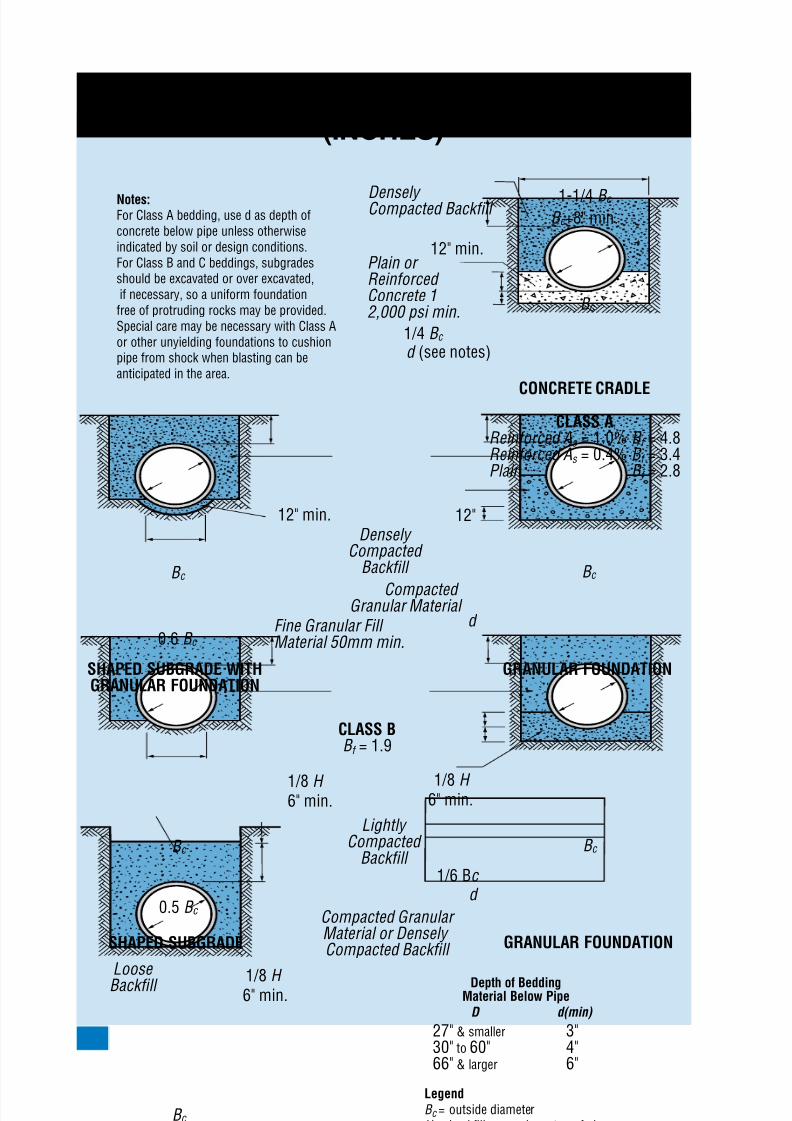
TRENCHBEDDINGCIRCULARPIPE(INCHES)
LegendB c = outside diameterH = backfill cover above top of pipeD = inside diameterd = depth of bedding material
below pipeAs
= area of transverse steel in thecradle of arch expressed as apercentage of area of concreteat invert or crown
Notes:For Class A bedding, use d as depth ofconcrete below pipe unless otherwiseindicated by soil or design conditions.For Class B and C beddings, subgradesshould be excavated or over excavated,if necessary, so a uniform foundationfree of protruding rocks may be provided.Special care may be necessary with Class Aor other unyielding foundations to cushionpipe from shock when blasting can beanticipated in the area.
B c
1-1/4 B c
0.6 B c
B c +8" min.
1/4 B c
d (see notes)
12" min.
CONCRETE CRADLE
1/8 H 6" min.
Lightly Compacted
Backfill
Loose
Backfill
Densely Compacted
Backfill
Densely Compacted Backfill
Plain or Reinforced Concrete 12,000 psi min.
Compacted Granular Material or Densely Compacted Backfill
Compacted Granular Material
Fine Granular Fill Material 50mm min.
1/8 H 6" min.
1/8 H 6" min.
B c
12" min. 12"
SHAPED SUBGRADE WITHGRANULAR FOUNDATION
GRANULAR FOUNDATION
B c
d
FLAT SUBGRADECLASS DB f = 1.1
CLASS AReinforced As = 1.0% B f = 4.8Reinforced As = 0.4% B f = 3.4Plain B f = 2.8
CLASS BB f = 1.9
B c
0.5 B c
B c
SHAPED SUBGRADE GRANULAR FOUNDATION
B c
d 1/6 Bc
Depth of BeddingMaterial Below Pipe
D d(min)
27" & smaller 3"30" to 60" 4"66" & larger 6"

8/7/2019 Concrete Pipe - Installation Guide
http://slidepdf.com/reader/full/concrete-pipe-installation-guide 33/91
American Concrete Pipe Association • www.concrete-pipe.org 33
TRENCHBEDDINGCIRCULARPIPE(MILLIMETERS)
Notes:For Class A bedding, use d as depth ofconcrete below pipe unless otherwiseindicated by soil or design conditions.For Class B and C beddings, subgradesshould be excavated or over excavated,if necessary, so a uniform foundationfree of protruding rocks may be provided.Special care may be necessary withClass A or other unyielding foundationsto cushion pipe from shock when blastingcan be anticipated in the area.
B c
1-1/4 B c
B c +200mm min.
1/4 B c
d (see notes)
300mm min.
CONCRETE CRADLE
Densely Compacted Backfill
Plain or Reinforced Concrete 113,800 kPa min.
0.6 B c
1/8 H
150mm min.
Lightly Compacted
Backfill
Loose
Backfill
Densely Compacted
Backfill
Compacted Granular Material or Densely Compacted Backfill
Compacted Granular Material
Fine Granular Fill Material 50mm min.
1/8 H 150mm min.
1/8 H
150mm min.
B c
300mm min. 300mm.
SHAPED SUBGRADE WITHGRANULAR FOUNDATION
GRANULAR FOUNDATION
B c
d
FLAT SUBGRADECLASS DB f = 1.1
LegendB c = outside diameterH = backfill cover above top of pipeD = inside diameterd = depth of bedding material
below pipeAs
= area of transverse steel in thecradle of arch expressed as apercentage of area of concreteat invert or crown
CLASS AReinforced As = 1.0% B f = 4.8Reinforced As = 0.4% B f = 3.4Plain B f = 2.8
CLASS BB f = 1.9
B c
0.5 B c
B c
SHAPED SUBGRADE GRANULAR FOUNDATION
B c
d 1/6 Bc
Depth of BeddingMaterial Below Pipe
D d(min) 675mm & smaller 75mm750mm to 1,500mm 100mm1,650mm & larger 150mm
8/7/2019 Concrete Pipe - Installation Guide
http://slidepdf.com/reader/full/concrete-pipe-installation-guide 34/91
American Concrete Pipe Association • www.concrete-pipe.org
TRENCHBEDDINGSELLIPTICAL&ARCHPIPE(INCHES)
0.7Bc
0.7Bc
Bc
Bc
CompactedGranularMaterial
Shapedto Fit
Shapedto Fit
Shapedto Fit
LightlyCompacted
Backfill
LightlyCompacted
Backfill
LightlyCompacted
Backfill
FineGranular Fill
Material2" min.
CompactedGranularMaterial
FineGranular FillMaterial2" min.
12"
0.7Bc
Bc
CompactedGranularMaterial
FineGranular FillMaterial2" min.
0.5 Bc
0.5Bc
Bc
Bc
6"
HORIZONTAL ELLIPTICAL PIPE
VERTICAL ELLIPTICAL PIPE
ARCH PIPE
12" 6"
12" 6"
CLASS BB f =1.9
CLASS CB f =1.5
CLASS B
B f =1.9
CLASS C
B f =1.5
CLASS BB f =1.9
0.7Bc
Bc
CLASS BB f =1.5
8/7/2019 Concrete Pipe - Installation Guide
http://slidepdf.com/reader/full/concrete-pipe-installation-guide 35/91
American Concrete Pipe Association • www.concrete-pipe.org 35
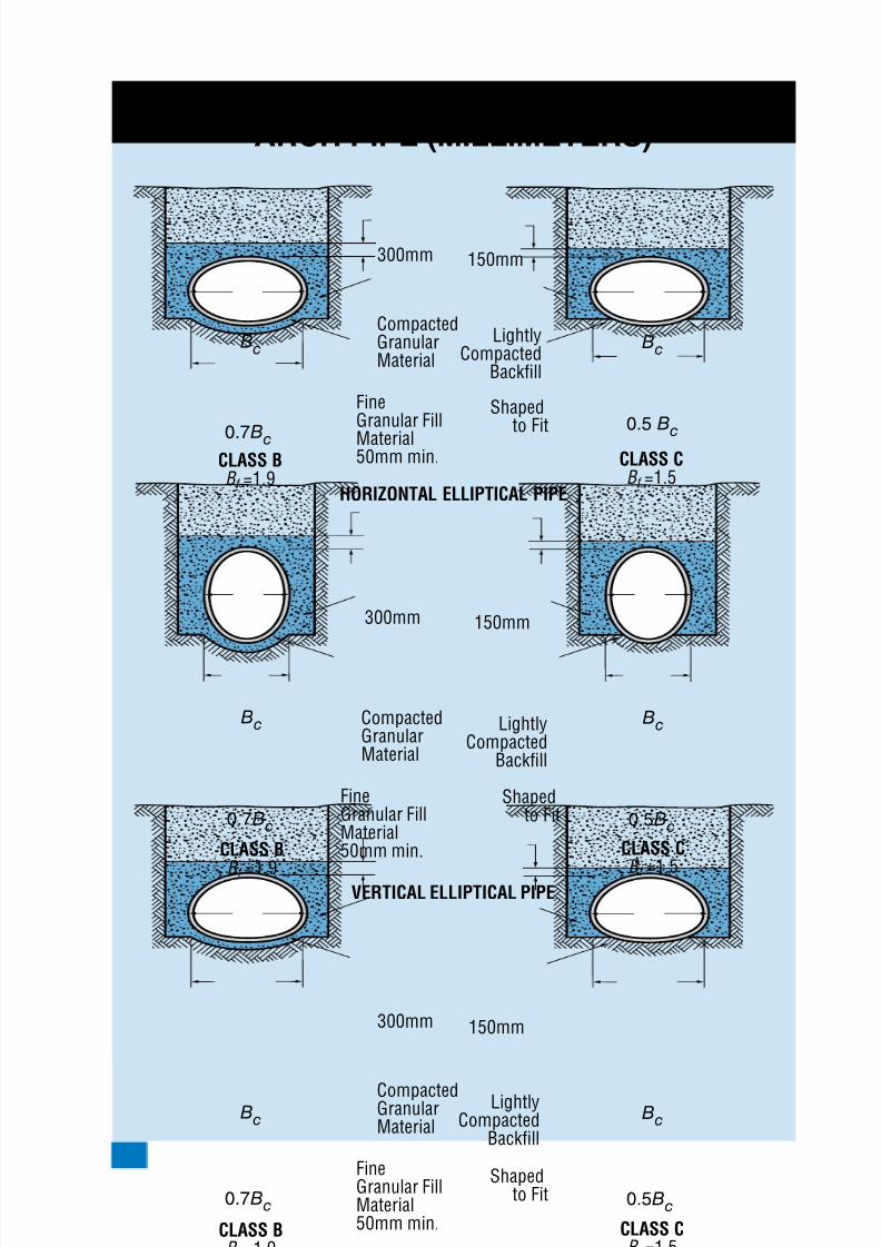
TRENCHBEDDINGSELLIPTICAL&ARCHPIPE(MILLIMETERS)
0.7Bc
0.7Bc
Bc
Bc
CompactedGranularMaterial
Shapedto Fit
Shapedto Fit
LightlyCompacted
Backfill
LightlyCompacted
Backfill
Shapedto Fit
LightlyCompacted
Backfill
FineGranular Fill
Material50mm min.
CompactedGranularMaterial
FineGranular FillMaterial50mm min.
300mm
0.7Bc
Bc
CompactedGranularMaterial
FineGranular FillMaterial50mm min.
300mm
300mm
0.5 Bc
0.5Bc
Bc
Bc
150mm
0.5Bc
Bc
150mm
150mm
HORIZONTAL ELLIPTICAL PIPE
VERTICAL ELLIPTICAL PIPE
ARCH PIPE
CLASS B
B f =1.9CLASS C
B f =1.5
CLASS B
B f =1.9
CLASS C
B f =1.5
CLASS B
B f =1.9CLASS C
B f =1.5
8/7/2019 Concrete Pipe - Installation Guide
http://slidepdf.com/reader/full/concrete-pipe-installation-guide 36/91
American Concrete Pipe Association • www.concrete-pipe.org
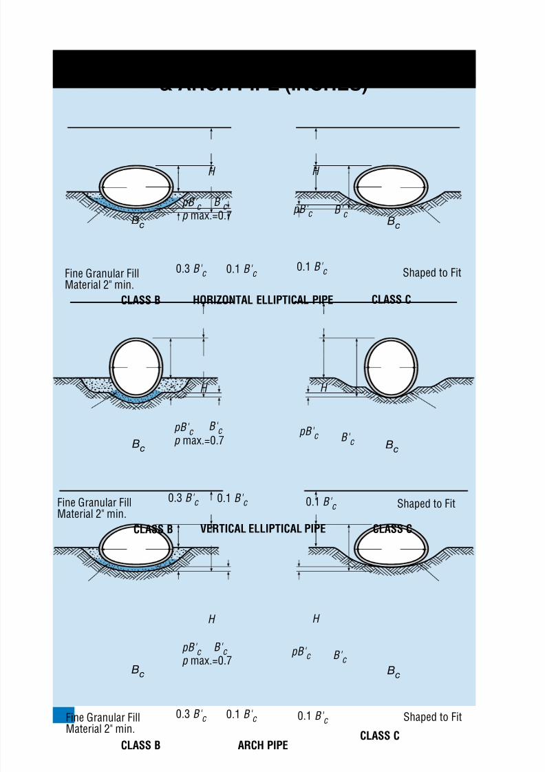
EMBANKMENTBEDDINGSELLIPTICAL&ARCHPIPE(INCHES)
Bc Bc
pB' c p max.=0.7
B' c B' c
B' c
0.3 B' c
H H
0.1 B' c
Bc Bc
Shaped to Fit
Shaped to Fit
Shaped to Fit
Fine Granular FillMaterial 2" min.
HORIZONTAL ELLIPTICAL PIPE
VERTICAL ELLIPTICAL PIPE
ARCH PIPE
CLASS B
pB' c p max.=0.7
pB' c
pB' c
pB' c
B' c B' c
0.3 B' c
H H
0.1 B' c 0.1 B' c
0.1 B' c
0.1 B' c
Fine Granular FillMaterial 2" min.
CLASS B CLASS C
CLASS C
Bc Bc
pB' c p max.=0.7
B' c
0.3 B' c
H H
0.1 B' c Fine Granular FillMaterial 2" min.
CLASS BCLASS C
8/7/2019 Concrete Pipe - Installation Guide
http://slidepdf.com/reader/full/concrete-pipe-installation-guide 37/91
American Concrete Pipe Association • www.concrete-pipe.org
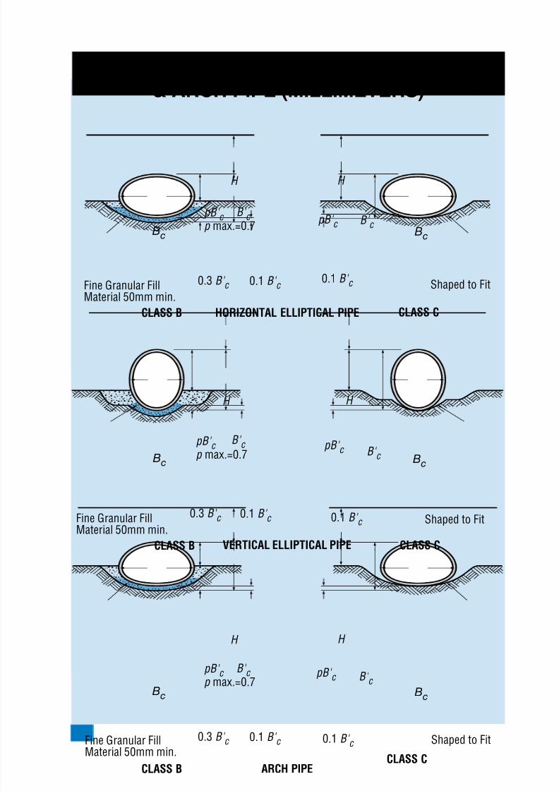
EMBANKMENTBEDDINGSELLIPTICAL&ARCHPIPE(MILLIMETERS)
Bc Bc
pB' c p max.=0.7
B' c B' c
B' c
0.3 B' c
H H
0.1 B' c
Bc Bc
Shaped to Fit
Shaped to Fit
Shaped to Fit
Fine Granular FillMaterial 50mm min.
HORIZONTAL ELLIPTICAL PIPE
VERTICAL ELLIPTICAL PIPE
ARCH PIPE
CLASS B
pB' c p max.=0.7
pB' c
pB' c
pB' c
B' c B' c
0.3 B' c
H H
0.1 B' c 0.1 B' c
0.1 B' c
0.1 B' c
Fine Granular FillMaterial 50mm min.
CLASS B CLASS C
CLASS C
Bc Bc
pB' c p max.=0.7
B' c
0.3 B' c
H H
0.1 B' c Fine Granular FillMaterial 50mm min.
CLASS BCLASS C
8/7/2019 Concrete Pipe - Installation Guide
http://slidepdf.com/reader/full/concrete-pipe-installation-guide 38/91
American Concrete Pipe Association • www.concrete-pipe.org
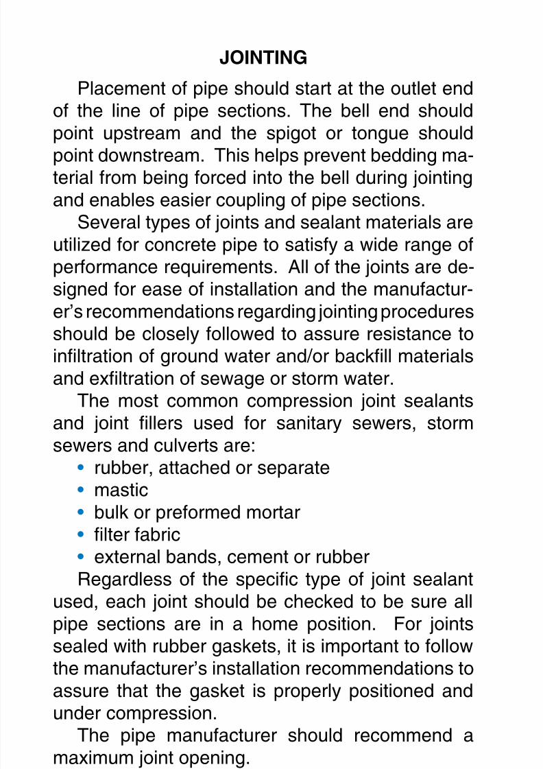
JOINTING
Placement of pipe should start at the outlet endof the line of pipe sections. The bell end should
point upstream and the spigot or tongue shouldpoint downstream. This helps prevent bedding ma-terial from being forced into the bell during jointingand enables easier coupling of pipe sections.
Several types of joints and sealant materials areutilized for concrete pipe to satisfy a wide range of
performance requirements. All of the joints are de-signed for ease of installation and the manufactur-er’s recommendations regarding jointing proceduresshould be closely followed to assure resistance toinltration of ground water and/or backll materialsand exltration of sewage or storm water.
The most common compression joint sealantsand joint llers used for sanitary sewers, stormsewers and culverts are:
rubber, attached or separatemasticbulk or preformed mortar
lter fabricexternal bands, cement or rubber
Regardless of the specic type of joint sealantused, each joint should be checked to be sure allpipe sections are in a home position. For jointssealed with rubber gaskets, it is important to follow
the manufacturer’s installation recommendations toassure that the gasket is properly positioned andunder compression.
The pipe manufacturer should recommend amaximum joint opening.
Rubber
There are numerous types of rubber gasketsused by pipe manufacturers. It is important that the
•••
••

8/7/2019 Concrete Pipe - Installation Guide
http://slidepdf.com/reader/full/concrete-pipe-installation-guide 39/91
American Concrete Pipe Association • www.concrete-pipe.org
gasket and/or pipe manufacturer’s recommendedprocedures be followed for every section of pipebeing installed. Illustrations are intended only as
CLEANBELL
CLEANSPIGOT
Carefully clean all dirtand foreign substancesfrom the jointing surfaceof the bell or groove endof pipe.
Improperly prepared belljointing surface mayprevent homing of thepipe.
Carefully clean spigot ortongue end of pipe,
including the gasketrecess.
Improperly preparedspigot and gasket recess
may prevent gasketfrom sealing correctly.
8/7/2019 Concrete Pipe - Installation Guide
http://slidepdf.com/reader/full/concrete-pipe-installation-guide 40/91
American Concrete Pipe Association • www.concrete-pipe.org0
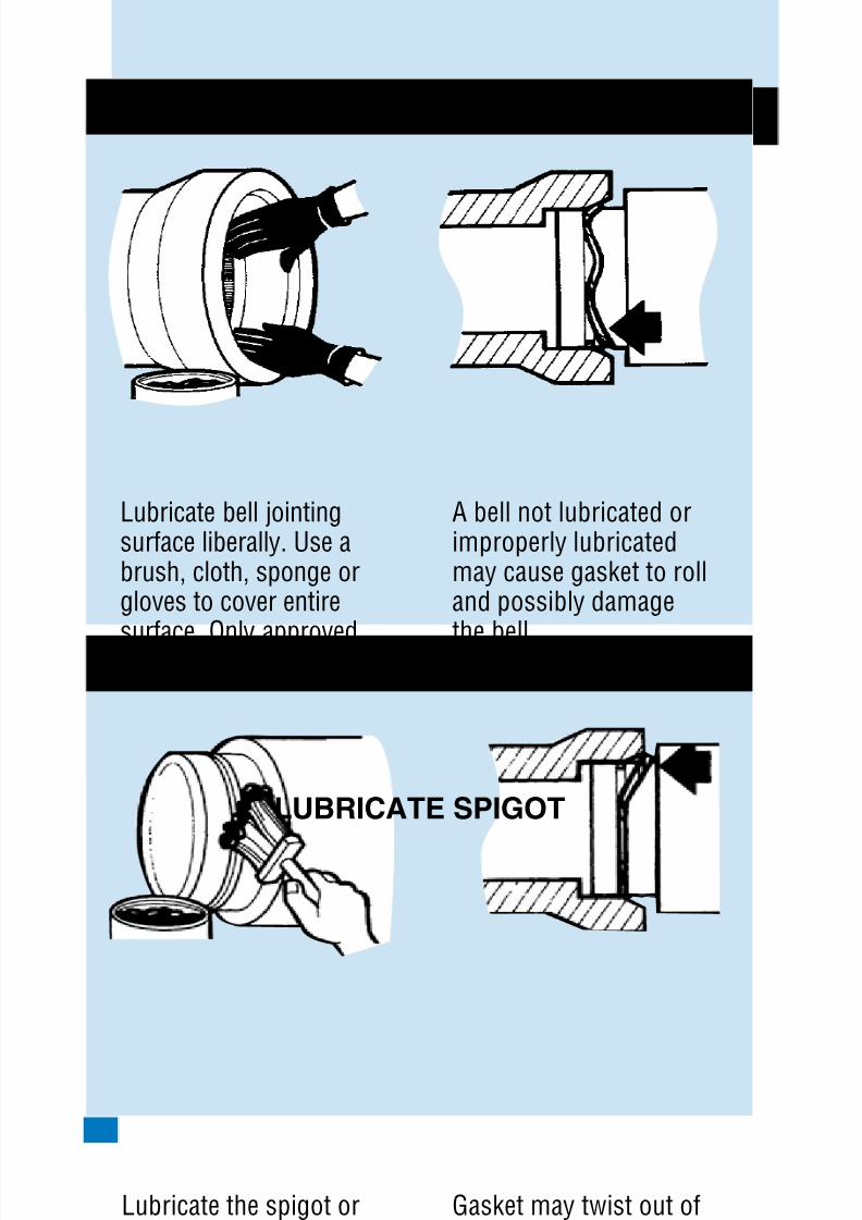
LUBRICATEBELL
LUBRICATESPIGOT
Lubricate bell jointingsurface liberally. Use abrush, cloth, sponge orgloves to cover entire
surface. Only approvedlubricant should be used.
A bell not lubricated orimproperly lubricatedmay cause gasket to rolland possibly damage
the bell.
Lubricate the spigot ortongue end of pipe,especially the gasketrecess.
Gasket may twist out ofrecess if lubricant inrecess is lacking orinsufficient.
8/7/2019 Concrete Pipe - Installation Guide
http://slidepdf.com/reader/full/concrete-pipe-installation-guide 41/91
American Concrete Pipe Association • www.concrete-pipe.org 1
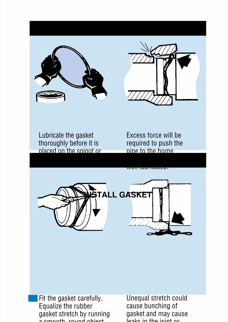
LUBRICATEGASKET
INSTALLGASKET
Lubricate the gasketthoroughly before it isplaced on the spigot ortongue.
Excess force will berequired to push thepipe to the homeposition if gasket is not
well lubricated.
Fit the gasket carefully.Equalize the rubbergasket stretch by runninga smooth, round object,inserted between gasket
and spigot, around theentire circumferenceseveral times.
Unequal stretch couldcause bunching ofgasket and may causeleaks in the joint orcrack the bell.
8/7/2019 Concrete Pipe - Installation Guide
http://slidepdf.com/reader/full/concrete-pipe-installation-guide 42/91
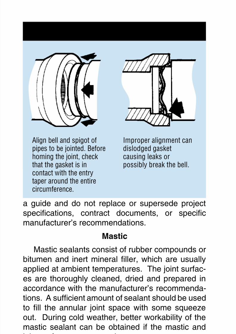
American Concrete Pipe Association • www.concrete-pipe.org
a guide and do not replace or supersede projectspecications, contract documents, or specicmanufacturer’s recommendations.
Mastic
Mastic sealants consist of rubber compounds orbitumen and inert mineral ller, which are usuallyapplied at ambient temperatures. The joint surfac-es are thoroughly cleaned, dried and prepared in
accordance with the manufacturer’s recommenda-tions. A sufcient amount of sealant should be usedto ll the annular joint space with some squeezeout. During cold weather, better workability of themastic sealant can be obtained if the mastic andjoint surfaces are warmed.
MortarMortar consists of portland cement paste, sand
ALIGNPIPE
Align bell and spigot ofpipes to be jointed. Beforehoming the joint, checkthat the gasket is in
contact with the entrytaper around the entirecircumference.
Improper alignment candislodged gasketcausing leaks orpossibly break the bell.
8/7/2019 Concrete Pipe - Installation Guide
http://slidepdf.com/reader/full/concrete-pipe-installation-guide 43/91
American Concrete Pipe Association • www.concrete-pipe.org
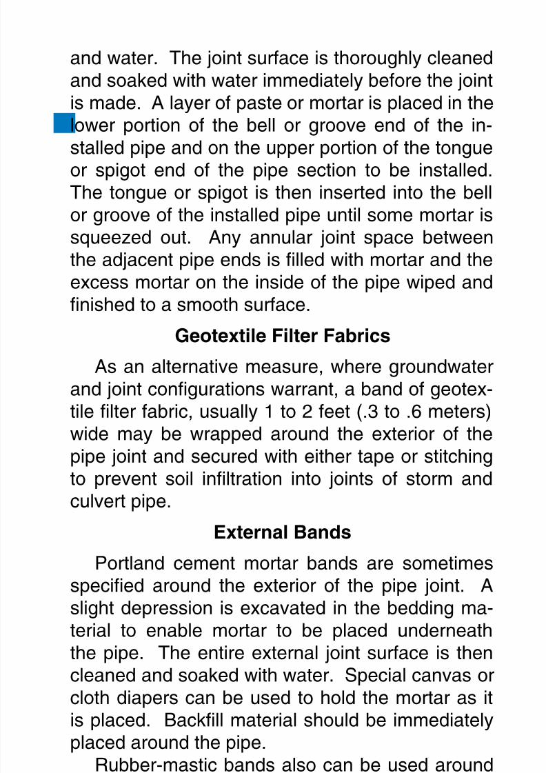
and water. The joint surface is thoroughly cleanedand soaked with water immediately before the jointis made. A layer of paste or mortar is placed in the
lower portion of the bell or groove end of the in-stalled pipe and on the upper portion of the tongueor spigot end of the pipe section to be installed.The tongue or spigot is then inserted into the bellor groove of the installed pipe until some mortar issqueezed out. Any annular joint space betweenthe adjacent pipe ends is lled with mortar and theexcess mortar on the inside of the pipe wiped andnished to a smooth surface.
GeotextileFilterFabrics
As an alternative measure, where groundwaterand joint congurations warrant, a band of geotex-
tile lter fabric, usually 1 to 2 feet (.3 to .6 meters)wide may be wrapped around the exterior of thepipe joint and secured with either tape or stitchingto prevent soil inltration into joints of storm andculvert pipe.
ExternalBandsPortland cement mortar bands are sometimes
specied around the exterior of the pipe joint. Aslight depression is excavated in the bedding ma-terial to enable mortar to be placed underneaththe pipe. The entire external joint surface is then
cleaned and soaked with water. Special canvas orcloth diapers can be used to hold the mortar as itis placed. Backll material should be immediatelyplaced around the pipe.
Rubber-mastic bands also can be used aroundthe exterior of the pipe joint. The bands are stretched
tightly around the barrel of the pipe and held rmlyin place by the weight of the backll material.
8/7/2019 Concrete Pipe - Installation Guide
http://slidepdf.com/reader/full/concrete-pipe-installation-guide 44/91
American Concrete Pipe Association • www.concrete-pipe.org
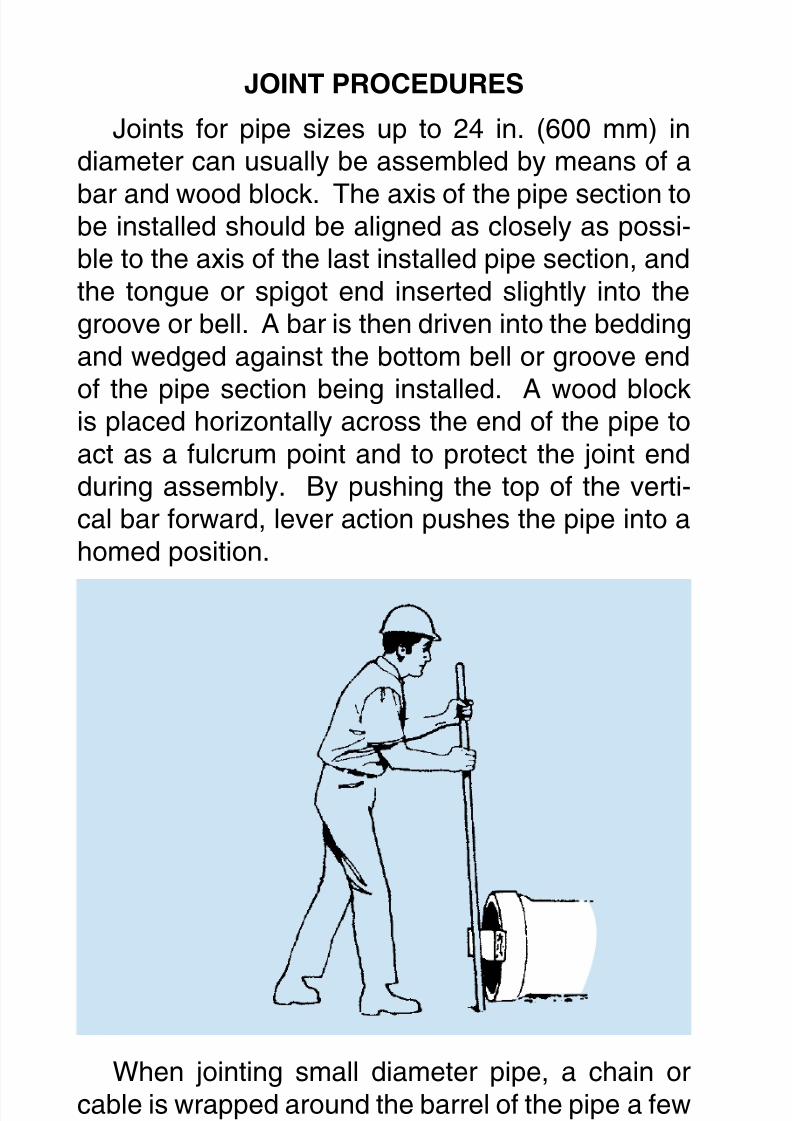
JOINTPROCEDURES
Joints for pipe sizes up to 24 in. (600 mm) indiameter can usually be assembled by means of a
bar and wood block. The axis of the pipe section tobe installed should be aligned as closely as possi-ble to the axis of the last installed pipe section, andthe tongue or spigot end inserted slightly into thegroove or bell. A bar is then driven into the beddingand wedged against the bottom bell or groove end
of the pipe section being installed. A wood blockis placed horizontally across the end of the pipe toact as a fulcrum point and to protect the joint endduring assembly. By pushing the top of the verti-cal bar forward, lever action pushes the pipe into ahomed position.
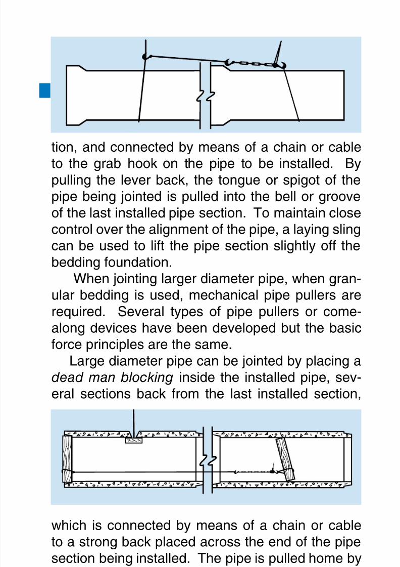
When jointing small diameter pipe, a chain orcable is wrapped around the barrel of the pipe a fewfeet behind the tongue or spigot and fastened with
a grab hook or other suitable connecting device. Alever assembly is anchored to the installed pipe,several sections back from the last installed sec-
8/7/2019 Concrete Pipe - Installation Guide
http://slidepdf.com/reader/full/concrete-pipe-installation-guide 45/91
American Concrete Pipe Association • www.concrete-pipe.org
tion, and connected by means of a chain or cableto the grab hook on the pipe to be installed. Bypulling the lever back, the tongue or spigot of the
pipe being jointed is pulled into the bell or grooveof the last installed pipe section. To maintain closecontrol over the alignment of the pipe, a laying slingcan be used to lift the pipe section slightly off thebedding foundation.
When jointing larger diameter pipe, when gran-
ular bedding is used, mechanical pipe pullers arerequired. Several types of pipe pullers or come-along devices have been developed but the basicforce principles are the same.
Large diameter pipe can be jointed by placing adead man blocking inside the installed pipe, sev-
eral sections back from the last installed section,
which is connected by means of a chain or cableto a strong back placed across the end of the pipesection being installed. The pipe is pulled home bylever action similar to the external assembly.
Mechanical details of the specic apparatusused for pipe pullers or come-along devices mayvary, but the basic lever action principle is used to
8/7/2019 Concrete Pipe - Installation Guide
http://slidepdf.com/reader/full/concrete-pipe-installation-guide 46/91
American Concrete Pipe Association • www.concrete-pipe.org46
develop the necessary controlled pulling force.The use of excavating equipment to push pipe
sections should be done with extreme caution. The
force applied by such equipment can damage thepipe. Direct contact between installation machineryand the pipe is prohibited. Use appropriate cushionmaterial between the pipe and the machine to pre-vent spalling.
SERVICECONNECTIONS
When a pipe connects to a rigid structure suchas a building, manhole or junction chamber, thebedding and foundation for the connecting pipesection should be highly compacted to minimizedifferential settlement. Differential settlement canresult in the pipe being sheared or cracked at the
connection. Special connectors are available whichprovide exibility between the connecting pipe andthe structure.
CURVEDALIGNMENT
Changes in direction of sewer lines are usually
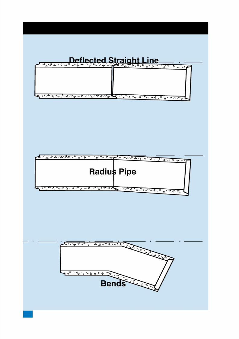
accomplished at manhole structures, while gradeand alignment changes in concrete pipe sewerscan be incorporated into the line through the useof deected straight pipe, radius pipe or specials.Since manufacturing and installation feasibility aredependent on the particular method used to negoti-
ate a curve, it is important to establish the methodprior to trench excavation. For deected straightpipe the joint of each pipe section is opened up onone side while the other side remains in the homeposition. The difference between the home andopened joint space is generally designated as the
pull. The maximum permissible pull must be limitedto that opening which will provide satisfactory jointperformance. This varies for different joint congu-

8/7/2019 Concrete Pipe - Installation Guide
http://slidepdf.com/reader/full/concrete-pipe-installation-guide 47/91
American Concrete Pipe Association • www.concrete-pipe.org 47
rations and is best obtained from the pipe manu-facturer.
Radius pipe, also referred to as beveled or mi-
tered pipe, incorporates the deection angle into thepipe joint. The pipe is manufactured by shorteningone side of the pipe and the amount of shorten-ing for any given pipe is dependent on manufactur-ing feasibility. Because of the possibility of greaterdeection angles per joint, sharper curvature withcorrespondingly shorter radii can be obtained withradius pipe than with deected straight pipe.
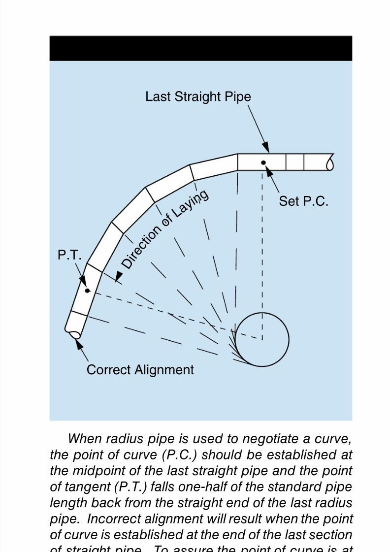
When establishing alignment for radius pipe, therst section of radius pipe should begin within onehalf of a radius pipe length of the point of curva-ture, and the last section of the radius pipe shouldextend one half of a radius pipe length beyond thepoint of tangent, as shown in the illustration Align-ment for Radius Pipe.
Special precast sections can be used for ex-tremely short radius curves which cannot be ne-gotiated with either deected straight pipe or withconventional radius pipe. Sharper curves can behandled by using special short lengths of radiuspipe rather than standard lengths.
One or more of these methods may be employedto meet the most severe alignment requirements.Since manufacturing processes and local standardsvary, local concrete pipe manufacturers should beconsulted to determine the availability and geomet-ric conguration of pipe sections to be installed oncurved alignment. In addition, many manufacturershave standardized joint congurations and deec-tions for specic radii and economies may be real-ized by using standard pipe.
8/7/2019 Concrete Pipe - Installation Guide
http://slidepdf.com/reader/full/concrete-pipe-installation-guide 48/91
American Concrete Pipe Association • www.concrete-pipe.org48
CURVED ALIGNMENT
Deflected Straight Line
Radius Pipe
Bends
8/7/2019 Concrete Pipe - Installation Guide
http://slidepdf.com/reader/full/concrete-pipe-installation-guide 49/91
American Concrete Pipe Association • www.concrete-pipe.org 49
When radius pipe is used to negotiate a curve,
the point of curve (P.C.) should be established at the midpoint of the last straight pipe and the point
of tangent (P.T.) falls one-half of the standard pipelength back from the straight end of the last radiuspipe. Incorrect alignment will result when the point of curve is established at the end of the last section
of straight pipe. To assure the point of curve is at the proper station it may be necessary for a special
short length of pipe to be installed in the line aheadof the point of curve.
ALIGNMENT FOR RADIUS PIPE
Last Straight Pipe
Set P.C.
Correct Alignment
P.T.D
irection of L
aying
8/7/2019 Concrete Pipe - Installation Guide
http://slidepdf.com/reader/full/concrete-pipe-installation-guide 50/91
American Concrete Pipe Association • www.concrete-pipe.org50
FINALBACKFILLING
Once the envelope of backll material is placedand properly compacted, the remainder of the ll or
backll should be placed and compacted to preventsettlement at the surface. Several types of com-paction equipment are available and certain typesare best for particular types of soils. The steelwheeled roller is best suited for compacting coarseaggregate such as slag, coarse gravel and graded
rock aggregates. The sheepsfoot roller is best forcohesive clays or silts, but is not suitable for useon granular soils. Specially designed rubber tiredrollers, which provide both static weight and knead-ing action, are applicable to many soils from claysto sand.
Regardless of the type of compaction equipmentused, the backll or ll material should be consis-tent with density requirements of the particular bed-ding specied.
ACCEPTANCETESTS
The physical tests included in the material speci-cations, under which the pipe is purchased, as-sure that pipe delivered to the job site meets or ex-ceeds the requirements established for a particularproject. The project specications usually includeacceptance test requirements to assure that rea-sonable quality control of workmanship and ma-terials has been realized during the constructionphase of the project. Soil density, line and grade,and visual inspection are all applicable tests for allstorm sewer, sanitary sewer and culvert projects.For sanitary sewers, limits are usually establishedfor inltration and exltration.
8/7/2019 Concrete Pipe - Installation Guide
http://slidepdf.com/reader/full/concrete-pipe-installation-guide 51/91
American Concrete Pipe Association • www.concrete-pipe.org 51
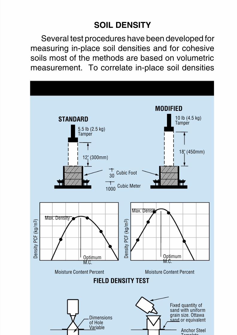
SOILDENSITY
Several test procedures have been developed formeasuring in-place soil densities and for cohesive
soils most of the methods are based on volumetricmeasurement. To correlate in-place soil densities
MOISTURE-DENSITY TEST
Compacted Sample
Removed from Hole
Moisture Content Percent
Density PCF (kg/m3)
Density PCF
(kg/m3)Max. Density
Max. Density
OptimumM.C.
12" (300mm)
5.5 lb (2.5 kg)Tamper
10 lb (4.5 kg)Tamper
18" (450mm)
OptimumM.C.
Moisture Content Percent
DETERMINATION OF VOLUME OF REMOVED SAMPLE
FIELD DENSITY TEST
STANDARD
MODIFIED
Dimensionsof HoleVariable
Fixed quantity ofsand with uniformgrain size. Ottawasand or equivalent
Cubic Meter1
1000
Cubic Foot1
30
Anchor SteelTemplate
8/7/2019 Concrete Pipe - Installation Guide
http://slidepdf.com/reader/full/concrete-pipe-installation-guide 52/91
American Concrete Pipe Association • www.concrete-pipe.org52
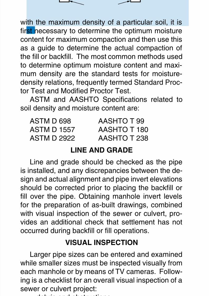
with the maximum density of a particular soil, it isrst necessary to determine the optimum moisturecontent for maximum compaction and then use this
as a guide to determine the actual compaction ofthe ll or backll. The most common methods usedto determine optimum moisture content and maxi-mum density are the standard tests for moisture-density relations, frequently termed Standard Proc-tor Test and Modied Proctor Test.
ASTM and AASHTO Specications related tosoil density and moisture content are:
ASTM D 698 AASHTO T 99ASTM D 1557 AASHTO T 180ASTM D 2922 AASHTO T 238
LINEANDGRADE
Line and grade should be checked as the pipeis installed, and any discrepancies between the de-sign and actual alignment and pipe invert elevationsshould be corrected prior to placing the backll orll over the pipe. Obtaining manhole invert levels
for the preparation of as-built drawings, combinedwith visual inspection of the sewer or culvert, pro-vides an additional check that settlement has notoccurred during backll or ll operations.
VISUALINSPECTION
Larger pipe sizes can be entered and examinedwhile smaller sizes must be inspected visually fromeach manhole or by means of TV cameras. Follow-ing is a checklist for an overall visual inspection of asewer or culvert project:
debris and obstructionsexcessive cracksjoints properly sealedinvert smooth and free of sags or high points
••••
8/7/2019 Concrete Pipe - Installation Guide
http://slidepdf.com/reader/full/concrete-pipe-installation-guide 53/91
American Concrete Pipe Association • www.concrete-pipe.org 53
stubs properly grouted and pluggedhookups, diversions and connections properlymade
catch basins and inlets properly connectedmanhole frames and covers properly installedsurface restoration and all other items perti-nent to the construction properly completed.
INFILTRATION
The inltration of excessive ground water into a
sanitary sewer can overload the capacity of a sew-er collection system and treatment facilities. The in-ltration test, conducted in accordance with ASTMC 969 (C 969M), is intended to demonstrate theintegrity of the installed materials and constructionprocedures, as related to the inltration of ground
water, and therefore, is only applicable if the watertable level is at least 2 ft. (600 mm) above the crownof the pipe for the entire length of the test section.Although the test is a realistic method of determin-ing water tightness, there are inherent difcultiesin applying the test criteria because of seasonal
uctuations in the water table and the problem ofcorrelating high ground water level conditions withactual test conditions.
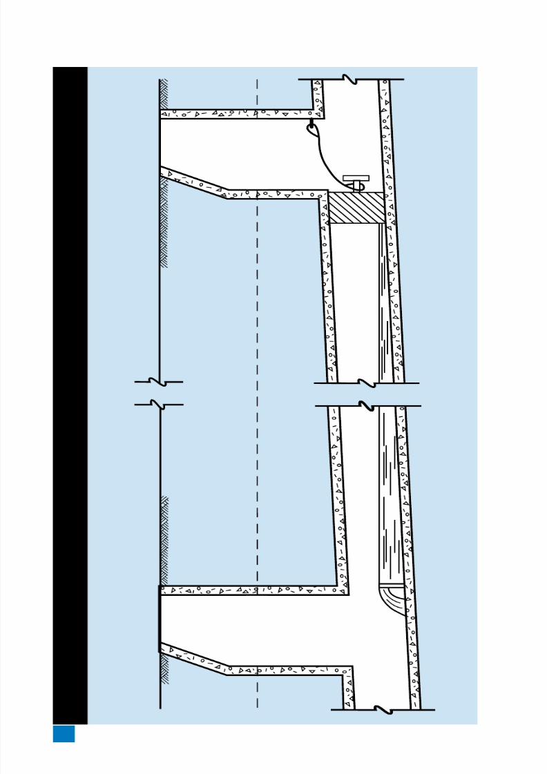
Before conducting the test, the water table shouldbe allowed to stabilize such that water completelysurrounds the pipe during the test period. The test
is usually conducted between adjacent manholeswith the upstream end of the sewer bulkheaded ina suitable manner to isolate the test section. Allservice laterals, stubs and ttings should be prop-erly plugged or capped at the connection to thetest pipe section to prevent the entrance of ground
water at these locations. A V-notch weir or othersuitable measuring device should be installed in the
••
•••
8/7/2019 Concrete Pipe - Installation Guide
http://slidepdf.com/reader/full/concrete-pipe-installation-guide 54/91
American Concrete Pipe Association • www.concrete-pipe.org54
INFILTRATION
TEST
8/7/2019 Concrete Pipe - Installation Guide
http://slidepdf.com/reader/full/concrete-pipe-installation-guide 55/91
American Concrete Pipe Association • www.concrete-pipe.org 55
inlet pipe to the downstream manhole. Inltratingwater is then allowed to build up and level off be-hind the weir until steady-uniform ow is obtained.
When steady ow occurs over the weir, leakage isdetermined by direct reading from graduations onthe weir or converting the ow quantity to gallonsper unit length of pipe per unit of time.
An important factor in applying the test criteria isto properly account for the variable water head overthe length of sewer being tested. The downstreamend of the test section will often be subjected to agreater external water pressure than the upstreamend. To compensate for this variable external pres-sure, the test pressure should be that pressure cor-responding to the average head of water over thetest section. Certain test sections may exceed theallowable inltration, limits, but the average inltra-tion for the total project should be within the leak-age limits established for the particular project. Theeffect of increased depth of groundwater on inltra-tion allowances must be considered. An averagehead of 6 ft. (1.8 m) of groundwater over the pipe isestablished as the base head. With heads of morethan 6 ft. (1.8 m), the inltration limit is increasedby the ratio of the square root of the actual aver-age head to the square root of the base head. Forexample, with an average groundwater head of 12ft. (3.7 m), the 200 gallons per inch (18.5 liters permm) of diameter per 1.0 mile (1.67 km) of pipe perday inltration limit should be increased by the ratioor the square root of the actual average head, 12ft. (1.8 m), to the square root of the base head 6ft. (1.8 m), which results in an allowable inltrationlimit of 282 gallons per inch (26.2 liters per mm) ofdiameter per mile (km) of pipe per day.
8/7/2019 Concrete Pipe - Installation Guide
http://slidepdf.com/reader/full/concrete-pipe-installation-guide 56/91
American Concrete Pipe Association • www.concrete-pipe.org56
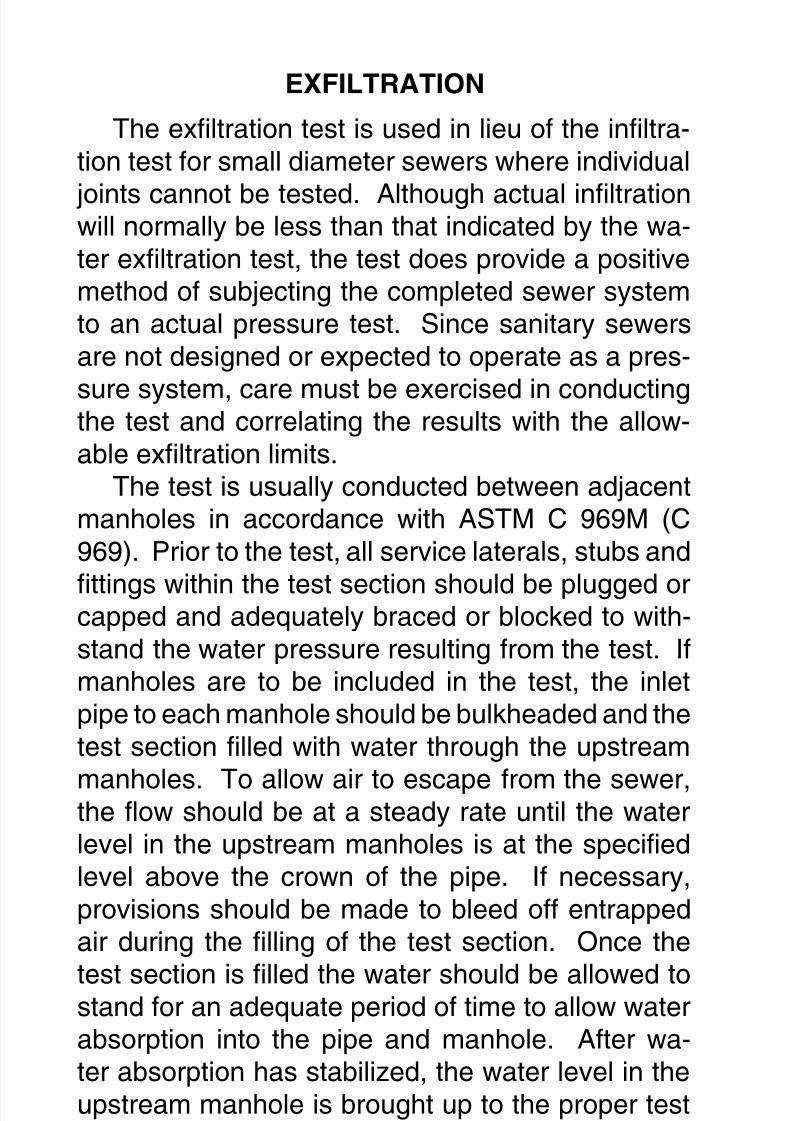
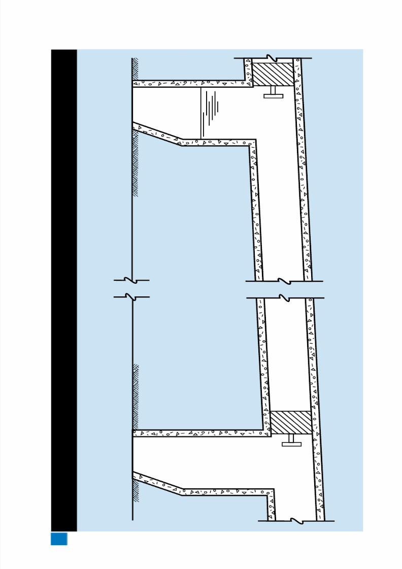
EXFILTRATION
The exltration test is used in lieu of the inltra-tion test for small diameter sewers where individual
joints cannot be tested. Although actual inltrationwill normally be less than that indicated by the wa-ter exltration test, the test does provide a positivemethod of subjecting the completed sewer systemto an actual pressure test. Since sanitary sewersare not designed or expected to operate as a pres-
sure system, care must be exercised in conductingthe test and correlating the results with the allow-able exltration limits.
The test is usually conducted between adjacentmanholes in accordance with ASTM C 969M (C969). Prior to the test, all service laterals, stubs and
ttings within the test section should be plugged orcapped and adequately braced or blocked to with-stand the water pressure resulting from the test. Ifmanholes are to be included in the test, the inletpipe to each manhole should be bulkheaded and thetest section lled with water through the upstream
manholes. To allow air to escape from the sewer,the ow should be at a steady rate until the waterlevel in the upstream manholes is at the speciedlevel above the crown of the pipe. If necessary,provisions should be made to bleed off entrappedair during the lling of the test section. Once the
test section is lled the water should be allowed tostand for an adequate period of time to allow waterabsorption into the pipe and manhole. After wa-ter absorption has stabilized, the water level in theupstream manhole is brought up to the proper testlevel. This level is established by measuring down
from the manhole cover or other convenient datumpoint.After a set period of time, the water elevation
8/7/2019 Concrete Pipe - Installation Guide
http://slidepdf.com/reader/full/concrete-pipe-installation-guide 57/91
American Concrete Pipe Association • www.concrete-pipe.org 57
EXFILTRATION TEST
8/7/2019 Concrete Pipe - Installation Guide
http://slidepdf.com/reader/full/concrete-pipe-installation-guide 58/91
American Concrete Pipe Association • www.concrete-pipe.org58
should be measured from the same reference pointand the loss of water during the test period calculat-ed, or the water can be restored to the level existing
at the beginning of the test, and the amount addedused to determine the leakage.To exclude both manholes from the test, it is nec-
essary to bulkhead the outlet pipe of the upstreammanhole. Provisions must be made in the bulkheadfor lling the pipe and expelling trapped air.
ASTM C 969 (C 969M) recommends the waterlevel at the upstream manhole to be a minimum of2 ft. (600 mm) above existing groundwater, or 2 ft.(600 mm) above the crown of the upstream pipe,whichever is greater. Since a sewer is installed ona grade, the test section downstream will be sub-jected to greater pressure. When the average headon the test section is greater than 3 ft. (900 mm),the allowable exltration limit should be adjustedin direct relationship to the ratio of the square rootof the average test head to the square root of thespecied base head, 3 ft. (900 mm).
The measured leakage of any individual sectiontested may exceed the leakage allowance speci-ed, provided the average of all sections testeddoes not exceed the specied leakage allowance.
AIRTESTING
The low-pressure air test conducted in accor-
dance with ASTM C 924 (C 924M) is a test, whichdetermines the rate at which air under pressure es-capes from an isolated section of sewer. The rateof air loss is intended to indicate the presence orabsence of pipe damage and whether or not thejoints have been properly constructed. The test is
not intended to indicate water leakage limits as nocorrelation has been found between air loss and
8/7/2019 Concrete Pipe - Installation Guide
http://slidepdf.com/reader/full/concrete-pipe-installation-guide 59/91
American Concrete Pipe Association • www.concrete-pipe.org 59
water leakage. The section of pipe to be tested isplugged at each end by means of inatable stop-pers. The ends of all laterals, stubs and ttings to
be included in the test should be plugged to preventair leakage, and securely braced to prevent pos-sible blowout due to internal air pressure. One ofthe plugs should have an inlet tap, or other provi-sion for connecting a hose to a portable air controlsource. The air equipment should consist of nec-essary values and pressure gauges to control therate at which air ows into the test section and toenable monitoring of the air pressure within the testsection.
Air is added to the test section until the internalair pressure is raised to a specied level and al-lowed to stabilize with the temperature of the pipewalls. The test is conducted by the pressure dropmethod, whereby, the air supply is disconnectedand the time required for the pressure to drop toa certain level is determined by means of a stop-watch. This time interval is then used to computethe rate of air loss. In applying low-pressure airtesting to sanitary sewers intended to carry uidunder gravity conditions, several important factorsshould be understood and precautions followedduring the test:
the air test is intended to detect defects in con-struction and pipe or joint damage and is notintended to be a measure of inltration or exl-tration leakage under service conditions, as nocorrelation has been found between air lossand water leakage.air test criteria are presently limited to concretepipe 24 in. (600 mm) in diameter and smallerby ASTM C924 (C 924M). Additional data isrequired to conrm the safety and applicability
•
•
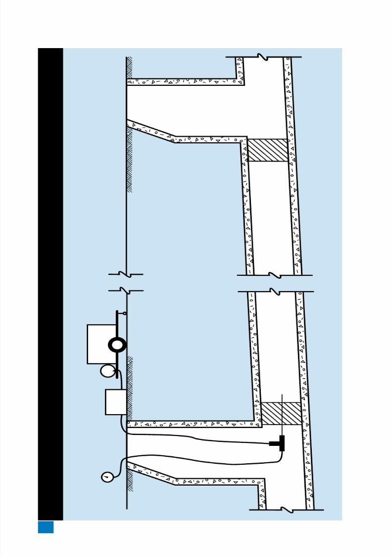
8/7/2019 Concrete Pipe - Installation Guide
http://slidepdf.com/reader/full/concrete-pipe-installation-guide 60/91
American Concrete Pipe Association • www.concrete-pipe.org60
AIR TEST
8/7/2019 Concrete Pipe - Installation Guide
http://slidepdf.com/reader/full/concrete-pipe-installation-guide 61/91
American Concrete Pipe Association • www.concrete-pipe.org 61
or develop criteria for pipe larger than 24 in. indiameter.plugs should be securely braced to prevent the
unintentional release of a plug which can be-come a high velocity projectile. Plugs shouldnot be removed until all air pressure in the testsection has been released.for safety reasons, no one should be allowedin the trench or manhole while the test is beingconducted.the testing apparatus should be equipped witha pressure relief device to prevent the possibil-ity of loading the test section with the full com-pressor capacity
VACUUMTESTING
The vacuum (negative air pressure) test is gov-erned by ASTM C 1214 (C 1214M) for pipe and C1244 (C 1244M) for manholes. This test involvesremoving air from the pipe or manhole to a speciedpressure less than atmospheric. The ability to holda vacuum or a slow drop indicates an acceptable
pipe or manhole. This test is not quantitative butprovides economical testing of large samples. Oth-er benets include the inherent safety and economyof vacuum systems over pressurized systems.
This test method for pipe covers 4 to 36 in. (100mm to 900 mm) diameter circular concrete pipe
sewer lines utilizing gasketed joints and may beperformed in the eld or at the plant as a prelimi-nary test. The ends of all laterals, stubs, and t-tings should be plugged to prevent air leakage. Airis evacuated from the pipeline until a specied neg-ative air pressure is reached. The drop in vacuum
during the test period is recorded. The vacuum lossin cubic feet per minute (cubic meters per second)is calculated and compared to the allowable value.
•
•
•
8/7/2019 Concrete Pipe - Installation Guide
http://slidepdf.com/reader/full/concrete-pipe-installation-guide 62/91
American Concrete Pipe Association • www.concrete-pipe.org62
JOINTTESTING-AIR
Joint testing according to ASTM C 1103 (C1103M) may be performed on installed precast
concrete pipe sewer lines, using either air or waterunder low pressure to demonstrate the integrity ofthe joint and the construction procedures.
When using either air or water, the joint to betested is covered on the inside of the pipe by a ringwith two end element sealing tubes. Prior to this the
interior joint surface of the pipe should be cleanedand wetted. The joint test apparatus should beplaced inside the pipe with the end element sealingtubes straddling both sides of the joint. Inate endelement sealing tubes with air in accordance withequipment and manufacturer’s recommendations.
For the joint air test, the void volume should bepressurized to a specied pressure greater than thepressure exerted by groundwater above the pipe.Allow the air pressure and temperature to stabilize,then shut off the air supply and start testing. Thepressure should drop less than the allowable speci-
ed pressure drop. If the joint being tested fails, itmay be repaired and retested.
When performing the joint water test, the bleed-off petcock must be located at top dead center of thepipe. Introduce water into the void volume until thewater ows evenly from the open petcock. Close
the petcock and pressurize the void to a speciedpressure above the groundwater pressure. Shut offthe water supply. The pressure should drop lessthan the allowable specied pressure drop. If thejoint being tested fails, it may be repaired and re-tested.
JOINTTESTING-WATER
Conducting exltration tests on large pipe is usu-
8/7/2019 Concrete Pipe - Installation Guide
http://slidepdf.com/reader/full/concrete-pipe-installation-guide 63/91
American Concrete Pipe Association • www.concrete-pipe.org 63
ally not practical because of the considerable quan-tity of water required. If the pipe is large enoughto be entered, each individual joint can be visually
inspected, and if necessary, subjected to a waterexltration test by means of test apparatus special-ly designed for this purpose. In this procedure, thejoint is isolated with an expanding shield equippedwith gaskets, which t tightly against the pipe wallson each side of the joint being tested. Throughappropriate piping, water is introduced into the an-nular space isolated by the shield and the leakagemeasured. The allowable leakage for individualjoints is that which would occur on the basis of theallowable water leakage for one pipe section.
8/7/2019 Concrete Pipe - Installation Guide
http://slidepdf.com/reader/full/concrete-pipe-installation-guide 64/91
American Concrete Pipe Association • www.concrete-pipe.org64
II.BOXCULVERTINSTALLATIONMANUAL
INTRODUCTION
With the development of national standards fordesign and manufacturing, box culverts are rapidlybecoming a large part of the precast industry. Oneof the unique benets of precast concrete boxesis their fast and easy installation, even under ad-verse eld and weather conditions. Precast boxes,
like concrete pipe, can be custom fabricated to anyconguration needed or desired in the eld. Wherelarger waterway capacity is required, multiple sec-tions can be placed side-by-side or connected inrows to provide an excellent storm water detentionsystem for areas with outfall ow restrictions or re-
quirements for on-site detention.This manual presents a guide for the properinstallation of concrete box culverts. While focus-ing on the construction of the box-soil system, thismanual also addresses those factors critical to thecompletion of the entire system, from delivery of the
box culverts to the jobsite, to the acceptance of theinstalled box line.This manual is intended as a guide and is not to
supersede the project specications.
8/7/2019 Concrete Pipe - Installation Guide
http://slidepdf.com/reader/full/concrete-pipe-installation-guide 65/91
American Concrete Pipe Association • www.concrete-pipe.org 65
PRE-INSTALLATION
PRECAUTIONS
The Safety and Health Regulations for Construc-tion under the Department of Labor, OccupationalSafety and Health Administration (OSHA), arepublished federal regulations covering safety mea-sures for all types of construction, including sewerand box culvert installations. All prime contractors
and subcontractors are subject to these regulationswhen involved in any type of construction, includ-ing alterations and repair work. Installers should beaware of these regulations.
Reviewing proper installation practices, whileconsidering the engineer’s design assumptions (in
relation to the use of trench boxes and backll com-paction requirements) will help to ensure workersafety as well as culvert longevity.
ORDERING,RECEIVING&HANDLING
Although the contractor is ordering the product,both the engineer and the supplier should be aware
of the proposed schedule of the contractor. Coordi-nation between the three parties will prevent unnec-essary delays. Much of the time the manufacturerstocks a wide range of box sizes for varied depths,however, manufacturing facilities must frequentlyadapt to meet job requirements. Therefore, for spe-
cial box types and large orders, prior knowledge willassist in correct and on-time delivery. When order-ing box culverts, specications should be in writingand should include:
Specication designationName and location of project
Box size, laying length and the bury depthTotal footage of each type and size of box
••
••
8/7/2019 Concrete Pipe - Installation Guide
http://slidepdf.com/reader/full/concrete-pipe-installation-guide 66/91
American Concrete Pipe Association • www.concrete-pipe.org66
Design live loadType of jointList of ttings
Material test requirementsJoint material and quantityInvoicing instructions
The following information should be clearlymarked on each box section:
Specication designationMinimum and maximum bury depthSpan, rise, table number, top of box and de-sign earth cover for ASTM C 1433 (Standard),C 1577 (LRFD)Date of manufactureName or trademark of the manufacturer
SCHEDULING/UNLOADING/PLACING/SEQUENCE
It is important to be prepared for the delivery ofevery box. The proper machinery should be avail-able to handle the unloading and placing of eachsection. Each shipment is tied down to avoid dam-
age during transport. However, it is the responsi-bility of the contractor to make certain no damagehas occurred during transit. An overall inspectionshould be performed upon arrival of the boxes. Be-fore unloading, the delivered box should be checkedagainst the order invoice to ensure accurate deliv-
ery of all items.If a box has been damaged it should be set
aside and recorded to ensure its proper order inthe installation sequence. In some cases damagedends, chips and cracks, which do not pass throughthe wall, can be repaired on site, while others are
irreparable and may have to be returned to the sup-plier for replacement.
•••
•••
•••
••
8/7/2019 Concrete Pipe - Installation Guide
http://slidepdf.com/reader/full/concrete-pipe-installation-guide 67/91
American Concrete Pipe Association • www.concrete-pipe.org 67
When unloading boxes, caution should be ex-ercised to ensure no personnel are in the path ofthe box as it is being moved. The box should be
handled per manufacturer’s recommendations.Use only manufacturer approved lifting devices tohandle box culvert sections. The box should be lift-ed and never dragged to avoid damage. If the liftingdevice could chip the box, padding should be pro-vided between the box and the lifting mechanism.
When a box is provided with lifting holes, the lift-ing device should pass through the wall and distrib-ute the weight along the inside wall of the box.
If the box is going to be installed directly from thetruck trailer to the nal location, a crane with stabi-lizers should be used. Be aware that some crawlerswithout outriggers, or backhoes, may not have thestability or maneuverability needed to line up theunits for proper installation.
If the box is going to be stored on-site, alterna-tive means can be used to transport the sections totheir temporary location. Care must be taken at alltimes and handling of boxes should be limited. Themanufacturer’s handling recommendations shouldbe followed at all times. Mishandling can result incracked bells and spigots.
Special boxes are normally shipped in the orderthey should be installed and therefore should bestored in the order of delivery.
STORING
Storing of boxes should be done as near to thenal installation destination as possible. If stackingof boxes is advisable, a at surface with no rocksshould be chosen for the rst layer. Follow the
manufacturer’s recommendations for an accept-able stack height.

8/7/2019 Concrete Pipe - Installation Guide
http://slidepdf.com/reader/full/concrete-pipe-installation-guide 68/91
American Concrete Pipe Association • www.concrete-pipe.org68
Gaskets and sealing materials should be storedin a cool dry place until needed. Rubber gasketsand bulk mastic or preformed mastics should be
kept clean and away from excessive heat. Somemastics may need to be heated under extreme coldconditions, and tar joint compound should also beheated for optimum behavior during application.
8/7/2019 Concrete Pipe - Installation Guide
http://slidepdf.com/reader/full/concrete-pipe-installation-guide 69/91
American Concrete Pipe Association • www.concrete-pipe.org 69
SITEPREPARATION
EXCAVATION
Trenches should be excavated to the dimensionsand grade specied on the plans or as ordered bythe owner. The width of the trenches should be keptto the minimum required for installation of the boxsections (ASCE 26-97). The trench width shouldtake into account the machinery needed to prop-
erly install the box section. Over excavated areasshould be backlled with approved materials andcompacted to the Standard Proctor density speci-ed for the leveling course.
Preparation of the site should establish a goodlevel grade, using ne to medium granular mate-
rial. When ledge rock, compacted rocky, or otherunyielding foundation material is encountered, itshould be removed to the requirements shown onthe plans. The foundation should be moderatelyrm to hard in-situ soil, stabilized soil or compactedll material. If unstable or unsuitable material is en-
countered, it should be removed and replaced withstable material approved by the engineer.Stockpiling excavated material adjacent to the
trench could cause a surcharge load, which maycave-in the trench walls. The ability of the trenchwalls to stand vertically under this additional loaddepends on the cohesive characteristics of the par-ticular type of material being excavated. This sur-charge load should be considered when evaluat-ing the need to provide trench support. It may benecessary where deep or wide trenches are beingexcavated to haul away a portion of the excavatedsoil or spread the stockpile with a bulldozer or otherequipment. If the excavated material is to be usedas backll, the stockpiled material should be visu-
8/7/2019 Concrete Pipe - Installation Guide
http://slidepdf.com/reader/full/concrete-pipe-installation-guide 70/91
American Concrete Pipe Association • www.concrete-pipe.org70
ally inspected for rocks, frozen lumps, highly plasticclay or other objectionable material. If the excavat-ed soil differs signicantly from the intended backll
material set forth in the plans, it may be necessaryto haul the unsuitable soil away and bring in selectbackll material.
TRENCHWATER
In the case where the water table is located inthe trench zone, dewatering methods must be em-
ployed to remove the water. The future location ofthe water table must also be considered due to itseffect on backll material and the box section. Thepresence of water around the box could cause o-tation of the box section, or migration of the backllmaterial. Migration of soil should be prevented, as
the backll is a means of support for the box.There are different methods that can be used to
remove this water: pumping, ditching, and/or pipingof the water. It should be noted that all pumpingshould be through a ltered discharge.
BEDDING/GRADEPrecast reinforced concrete box sections are de-
signed for installed conditions rather than test con-ditions. Designs are presented in ASTM StandardsC 1433(M) and C 1577(M), and AASHTO M 259(M)and M 273(M). Bedding details for box sections
are as illustrated. A proper foundation for a box cul-vert consists of specied bedding material havinguniform at surface characteristics (no low or highpoints), as these could create stress concentrationsin the box after installation. The box, once installed,will not normally settle; it cannot be forced down to
grade. Coarse bedding materials are not benecialdue to their irregular shape and sharp angles; in-stead medium to ne granular material should be

8/7/2019 Concrete Pipe - Installation Guide
http://slidepdf.com/reader/full/concrete-pipe-installation-guide 71/91
American Concrete Pipe Association • www.concrete-pipe.org 71
used (less than 1 1/2 in. preferred but no largerthan 2 in.). If the construction site is located in a re-gion where the ground is frozen, remove the frozen
lumps and replace them with designer approvedmaterial.A bedding thickness of no less than 3 in. (75 mm)
should be used except when the foundation is rock,in which case the bedding thickness should be 6 in.(150 mm). The width of the bedding material shouldequal the width of the box (span plus twice the wallthickness) and the length of the bedding materialshould equal the length of the box.
The box will tend to pull some bedding materialtoward the connection as it is aligned with the pre-vious box. Excess bedding material trapped in thejoint will prevent a proper alignment and connec-tion and hence should be prevented. Therefore, atthe connection end, a small trench (a shovel lengthwide and running the length of the bedding mate-rial) should be dug. This allows for the bedding ma-terial to fall into the trench instead of the joint whenthe box is pulled into place.
All bedding material characteristics should cor-respond to code and designer’s plans for the specif-ic project. Correct installation requires that the boxculvert be installed on properly graded bedding.Any discrepancies in the installation of the culvertregarding bedding or grade should be addressedwith the engineer for remedial action.
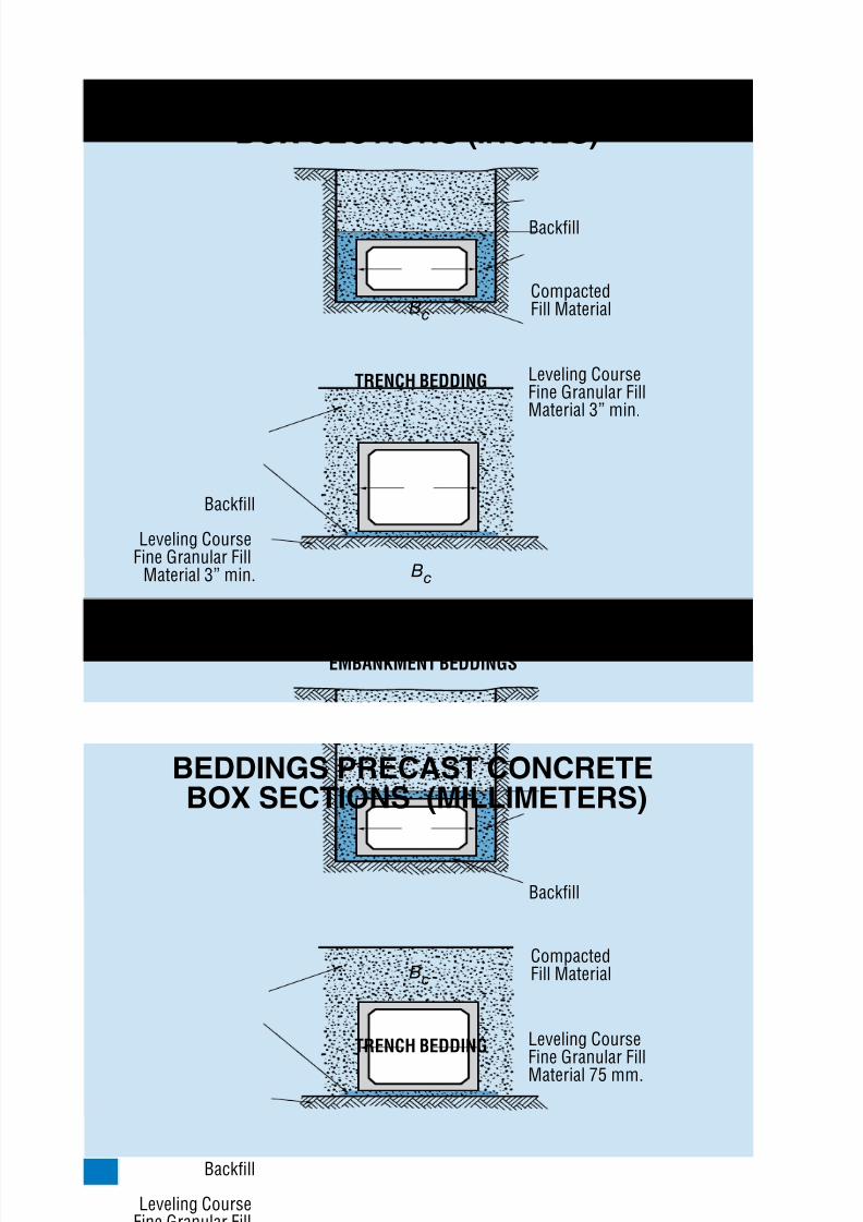
8/7/2019 Concrete Pipe - Installation Guide
http://slidepdf.com/reader/full/concrete-pipe-installation-guide 72/91
American Concrete Pipe Association • www.concrete-pipe.org72
BEDDINGSPRECASTCONCRETEBOXSECTIONS(INCHES)
Leveling CourseFine Granular FillMaterial 3” min.
CompactedFill MaterialB
c
Backfill
TRENCH BEDDING
Leveling CourseFine Granular Fill
Material 3” min.
Existing GroundFill
Bc
Backfill
EMBANKMENT BEDDINGS
BEDDINGSPRECASTCONCRETEBOXSECTIONS(MILLIMETERS)
Leveling CourseFine Granular FillMaterial 75 mm.
CompactedFill MaterialB
c
Backfill
TRENCH BEDDING
Leveling CourseFine Granular FillMaterial 75 mm.
Existing GroundFill
Bc
Backfill
EMBANKMENT BEDDINGS
8/7/2019 Concrete Pipe - Installation Guide
http://slidepdf.com/reader/full/concrete-pipe-installation-guide 73/91
American Concrete Pipe Association • www.concrete-pipe.org 73
INSTALLATION
BOXALIGNMENT
It is critical that the rst box sections be installedcorrectly as they will determine the line and gradeof the following boxes. If these are not correct, fu-ture connections may be affected.
BOXPLACEMENT
Placement of boxes should start at the outlet endof the line of box sections. The bell end should pointupstream and the spigot or tongue should pointdownstream. Unless otherwise approved by theowner, loads from construction equipment trans-ferred to a box section before, during, or after llplacement, either directly or through the ll, shouldnot be greater than the loads assumed in the de-sign (ASCE 26-97). Using excavating machineryfor the purpose of pushing boxes into place shouldbe avoided, since this could cause cracking, requir-ing on-site repairing. Also, dropping or dragging thesection over gravel or rock is not advised.
A proper foundation for construction equipmentshould be available in order to ensure that no dam-age is caused to the leveling course and the side-walls of the excavation area.
JOINTING
Jointing is important in reducing the migration ofsoil nes and water between box sections and theirsurroundings. Depending on the use of the box cul-vert, various materials and methods may be usedfor sealing the joints.
Box culverts specied for a soil-tight joint can be
sealed between the joint with a bituminous masticsealant. Either liquid butyl (bulk mastic) or non-shrink grout can be added to the outside top slab
8/7/2019 Concrete Pipe - Installation Guide
http://slidepdf.com/reader/full/concrete-pipe-installation-guide 74/91
American Concrete Pipe Association • www.concrete-pipe.org74
and applied down the sidewall 12 in. (300 mm) aswell as applied to the inside bottom slab and in-side sidewalls; or butyl sealant 1 in. (25 mm) thick
and placed on the inside bottom and halfway upthe sides of the bell end (approximately 1/2 in. (13mm) from edge) and placed on the outside top andhalfway down the sides of the spigot end (approx-imately 1/2 in. (13 mm) from edge) can be usedto seal a soil tight joint. In cold weather it may benecessary to heat the butyl sealant with a hot wa-ter bath, bottle gas torch, or both. Placing this jointmaterial in a sunny location, just prior to use, willallow heat absorption and make it more workable.Different grades of joint material are available fordifferent temperatures.
Another joint commonly used is an extrudedsealant which is placed between the joints. The ex-truded sealant can be applied in the same manneras the bituminous sealant, applied to the bell andspigot end of the sections being joined. In someareas, rubber gasket box joints may be available.Pre-made foam gaskets can also be used to sealjoints. However these forms of sealant will have tobe manually attached to the bottom of the spigotend of the box to prevent sagging.
If the seal is insufcient then an added layer ofadhesive joint wrap (butyl rubber laminated to poly-ethylene vapor retarder) can be used on the out-side of the box to prevent inltration. The externalsealing band can also be non-woven geotextile andshould be placed on the sides and top of the boxafter installation. In certain situations all four sidescan be wrapped. In this case the geotextile materialcan be slipped under the box before it is set thenthe sides and top can be sealed after the box is inplace. It is desirable for the sealant to be one con-
8/7/2019 Concrete Pipe - Installation Guide
http://slidepdf.com/reader/full/concrete-pipe-installation-guide 75/91
American Concrete Pipe Association • www.concrete-pipe.org 75
tinuous strip, however if this is not practical, thenthe top strip should be one piece and extend downthe sides of the box a distance of 12 in. (300 mm)
and overlap with the strip extending from the bot-tom.
CONNECTINGTHEBOXES
When joining boxes together, chains or winchesshould be used. Direct contact between installationmachinery and the box sections is prohibited. Use
appropriate cushion material between the box sec-tion and the machine to prevent spalling.
Before placing the box culvert in its nal location,check to see that the grade is correct, the joint sur-face is cleared of all bedding material and the jointsealant is properly seated.
A workman should be in a position to guide thecrane operator as the box is being aligned. Theworkman in the alignment position should direct thecrane operator to lower the box until the top slabof the box section is approximately two feet abovethe top slab of the previously placed box. The box
should be lowered in such a way that the sides ofthe boxes are ush and the spigot end of the in-stalled box slips in line with the bell end of the re-ceiving section. Even though the box is in the rightposition the weight of the section should be main-tained by the crane.
Now the joint needs to be secured. This can bedone through the use of winches or come-a-longs.Place one end of the come-a-long or winch at thefar end of the installed sections and over the outerend of the next section taking care not to spall eachsurface. This works best if a pair of winches or
come-alongs are used, one on each side. Gradu-ally tighten the chains until the box section is snugagainst the previously placed box. This winching
8/7/2019 Concrete Pipe - Installation Guide
http://slidepdf.com/reader/full/concrete-pipe-installation-guide 76/91
American Concrete Pipe Association • www.concrete-pipe.org76
should be done uniformly. If the joint is not within themaximum allowable joint opening, the crane shouldcarefully lift the section slightly without breaking out
the joint on top while the winches are pulling thechains taut. If this does not x the open joint – re-move the section and re-screed the bedding. Alsocheck the sections to make sure that the dimen-sional tolerances will allow the joint to go home.When the box is in the right position the crane cangradually release the box so that the bedding mate-rial carries the entire weight of the box and then itcan be disconnected. The chains are held securelyuntil the crane is disconnected, and then they arereleased.
COMPLETION
After the boxes have been joined together the liftholes should be plugged according to the manufac-turer’s recommendation.
BACKFILL
Backll should be placed in uniform layers along
the sides of the boxes and over the top of the boxsections. These layers should be no greater than themaximum allowed to achieve the required density.The characteristics of the backll material shouldbe determined from the contract specications andshould contain no debris, organic matter, frozen
material or large stones with a diameter greaterthan 1/2 the thickness of the compacted layers be-ing placed. When vibratory methods are needed tocompact the backll material, care should be takenso that no damage is done to the box section.
If sheathing and trench shields are used and are
not part of the designer’s soil structure plan, theyshould be incrementally removed, depending onthe availability and readiness of backll material.
8/7/2019 Concrete Pipe - Installation Guide
http://slidepdf.com/reader/full/concrete-pipe-installation-guide 77/91
American Concrete Pipe Association • www.concrete-pipe.org 77
When trench shields are removed take care notto disturb the installed boxes. Restraining the boxmay be necessary to hold it in place. If any voids
are created in the side ll material they should belled and compacted.Once the envelope of backll material is placed
and properly compacted, the remainder of the llor backll should be placed and compacted to pre-vent settlement at the surface. Compaction andequipment loads should not exceed the pipe designstrength. Several types of compaction equipmentare available and certain types are best for particu-lar types of soils. The steel wheeled roller is bestsuited for compacting coarse aggregate such asslag, coarse gravel and graded rock aggregates.The sheepsfoot roller is best for cohesive clays orsilts, but is not suitable for use on granular soils.Specially designed rubber tired rollers, which pro-vide both static weight and kneading action, are ap-plicable to many soils from clays to sand.
Regardless of the type of compaction equipmentused, the backll or ll material should be consis-tent with density requirements of the particular in-stallation specied.
MINIMUMCOVERFOR
CONSTRUCTIONLOADS
If construction equipment is going to travel over
installed box sections, compacted backll shouldbe placed to a minimum of 3 ft. (1 m) over the topof the box section unless the box has been spe-cically designed for the anticipated constructionloads. Above all, the loads applied to the box sec-tion should not exceed those specied by the de-
signer. In an embankment installation, the minimumamount of backll should extend one box section
8/7/2019 Concrete Pipe - Installation Guide
http://slidepdf.com/reader/full/concrete-pipe-installation-guide 78/91
American Concrete Pipe Association • www.concrete-pipe.org78
span or 3 ft. (1 m), whichever is larger, in each di-rection to prevent lateral displacement. If construc-tion trafc is large, the crossing point should be oc-
casionally changed so that lateral displacement isminimized.
VISUALINSPECTION
Large box sections can be entered and exam-ined. TV cameras are another means of visuallyinspecting installed boxes. A checklist is provided
below for an overall visual inspection of a sewer orculvert project.
DebrisExcessive cracks or large cracksJoints properly sealedInvert smooth and free of sags or high points
Lift holes properly lledHookups, diversions and connections properlymadeCatch basins and inlets properly connectedManhole frames and covers properly installedSurface restoration and all other items perti-
nent to the construction properly completed.
••••
••
•••
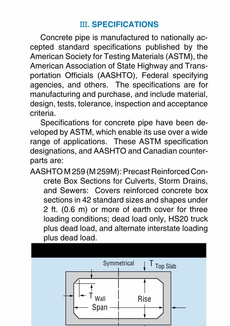
8/7/2019 Concrete Pipe - Installation Guide
http://slidepdf.com/reader/full/concrete-pipe-installation-guide 79/91
American Concrete Pipe Association • www.concrete-pipe.org 79
III.SPECIFICATIONS
Concrete pipe is manufactured to nationally ac-cepted standard specications published by the
American Society for Testing Materials (ASTM), theAmerican Association of State Highway and Trans-portation Ofcials (AASHTO), Federal specifyingagencies, and others. The specications are formanufacturing and purchase, and include material,design, tests, tolerance, inspection and acceptance
criteria.Specications for concrete pipe have been de-
veloped by ASTM, which enable its use over a widerange of applications. These ASTM specicationdesignations, and AASHTO and Canadian counter-parts are:
AASHTO M 259 (M 259M): Precast Reinforced Con-crete Box Sections for Culverts, Storm Drains,and Sewers: Covers reinforced concrete boxsections in 42 standard sizes and shapes under2 ft. (0.6 m) or more of earth cover for threeloading conditions; dead load only, HS20 truck
plus dead load, and alternate interstate loadingplus dead load.
BOX SECTION
T Top Slab
T Wall
T Bottom Slab
Symmetrical
RiseSpan
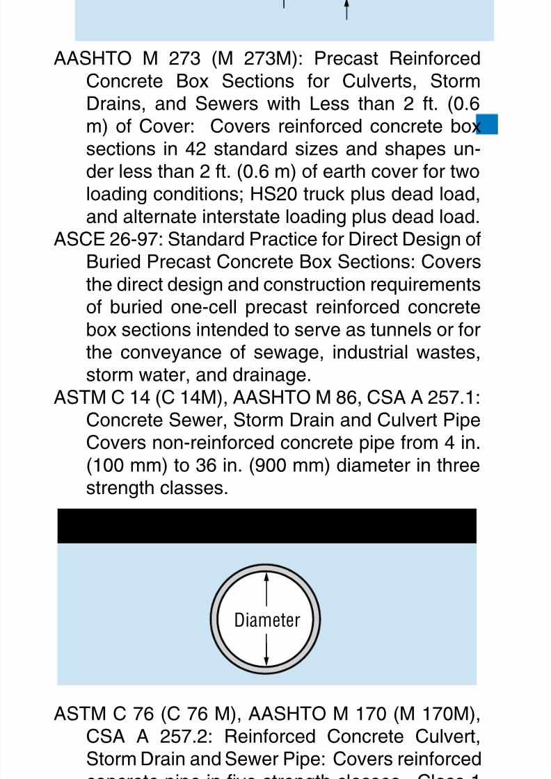
8/7/2019 Concrete Pipe - Installation Guide
http://slidepdf.com/reader/full/concrete-pipe-installation-guide 80/91
American Concrete Pipe Association • www.concrete-pipe.org80
AASHTO M 273 (M 273M): Precast ReinforcedConcrete Box Sections for Culverts, StormDrains, and Sewers with Less than 2 ft. (0.6
m) of Cover: Covers reinforced concrete boxsections in 42 standard sizes and shapes un-der less than 2 ft. (0.6 m) of earth cover for twoloading conditions; HS20 truck plus dead load,and alternate interstate loading plus dead load.
ASCE 26-97: Standard Practice for Direct Design ofBuried Precast Concrete Box Sections: Coversthe direct design and construction requirementsof buried one-cell precast reinforced concretebox sections intended to serve as tunnels or forthe conveyance of sewage, industrial wastes,storm water, and drainage.
ASTM C 14 (C 14M), AASHTO M 86, CSA A 257.1:Concrete Sewer, Storm Drain and Culvert PipeCovers non-reinforced concrete pipe from 4 in.(100 mm) to 36 in. (900 mm) diameter in threestrength classes.
ASTM C 76 (C 76 M), AASHTO M 170 (M 170M),CSA A 257.2: Reinforced Concrete Culvert,Storm Drain and Sewer Pipe: Covers reinforcedconcrete pipe in ve strength classes. Class 1– 60 to 144 in. (1500 mm to 3600 mm), ClassesII, III, IV, V are for 12 in. to 144 in. (300 mm to3600 mm). Larger sizes and higher classes areavailable as special designs.
CIRCULAR
Diameter
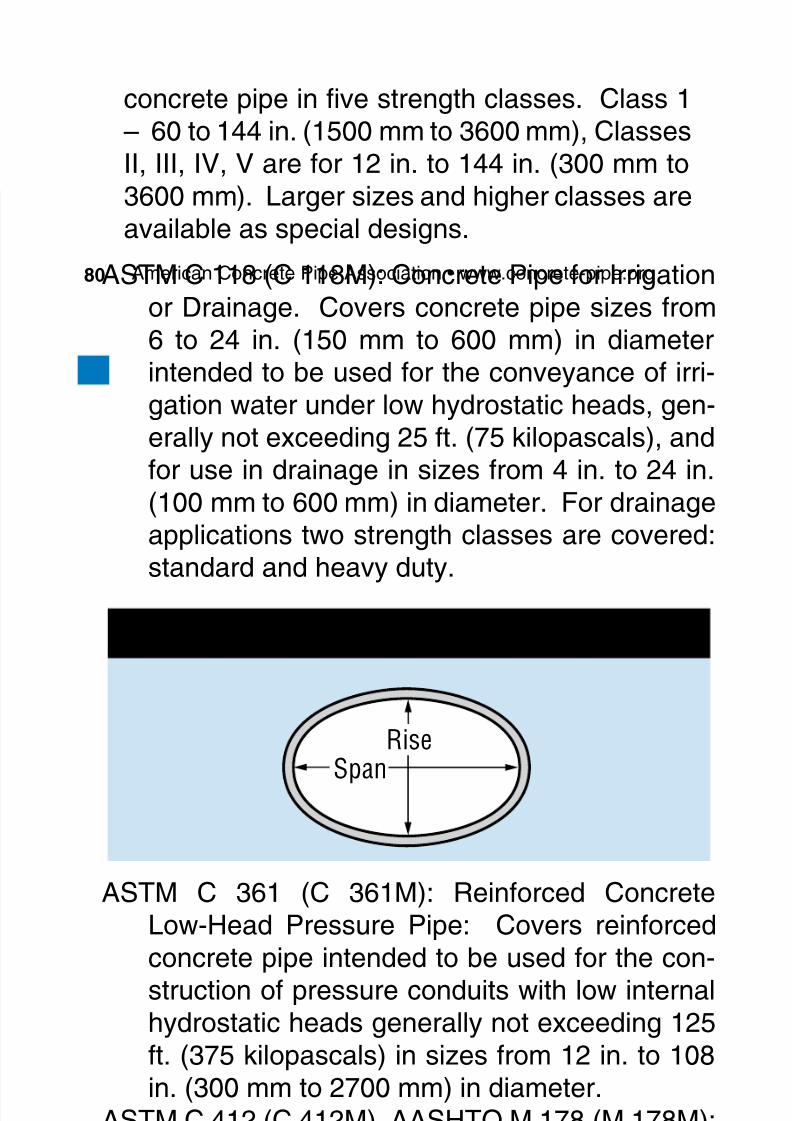
8/7/2019 Concrete Pipe - Installation Guide
http://slidepdf.com/reader/full/concrete-pipe-installation-guide 81/91
American Concrete Pipe Association • www.concrete-pipe.org 81
ASTM C 118 (C 118M): Concrete Pipe for Irrigationor Drainage. Covers concrete pipe sizes from6 to 24 in. (150 mm to 600 mm) in diameter
intended to be used for the conveyance of irri-gation water under low hydrostatic heads, gen-erally not exceeding 25 ft. (75 kilopascals), andfor use in drainage in sizes from 4 in. to 24 in.(100 mm to 600 mm) in diameter. For drainageapplications two strength classes are covered:standard and heavy duty.
ASTM C 361 (C 361M): Reinforced ConcreteLow-Head Pressure Pipe: Covers reinforcedconcrete pipe intended to be used for the con-struction of pressure conduits with low internalhydrostatic heads generally not exceeding 125ft. (375 kilopascals) in sizes from 12 in. to 108in. (300 mm to 2700 mm) in diameter.
ASTM C 412 (C 412M), AASHTO M 178 (M 178M):Concrete Drain Tile: Covers non-reinforcedconcrete drain tile with internal diametersfrom 4 in. to 36 in. (100 mm to 900 mm). Fourstrength classes are covered, standard quality,extra quality, special quality, and heavy-dutyextra quality.
ASTM C 443 ( C 443M), AASHTO M 198 (M 198M),CSA A 257.3: Joints for Circular ConcreteSewer and Culvert Pipe, with Rubber Gaskets:
HORIZONTAL ELLIPTICAL
Span
Rise
8/7/2019 Concrete Pipe - Installation Guide
http://slidepdf.com/reader/full/concrete-pipe-installation-guide 82/91
American Concrete Pipe Association • www.concrete-pipe.org82
Covers joints where inltration or exltration isa factor in the design, including the design ofjoints and the requirements for rubber gaskets
to be used therewith for pipe conforming in allother respects to ASTM C 14 (C 14M) or ASTMC 76 (C 76M).
ASTM C 444 (C 444M), AASHTO M 175 (M 175M):Perforated Concrete Pipe: Covers perforatedconcrete pipe intended to be used for underd-rainage in sizes 4 in. to 27 in. (100 mm to 675mm) and larger in diameter.
ASTM C 478 (C 478M), AASHTO M 199 (M 199M):Precast Reinforced Concrete Manhole Sec-tions: Covers precast reinforced concrete man-hole riser sections and appurtenances such asgrade rings, tops and special sections for use insewer and water works.
ASTM C 497 (C 497M), AASHTO T 33, CSA A257.0: Testing of Concrete Pipe or Tile: Coversprocedures for testing concrete pipe or tile.
ASTM C 505 (C 505M): Non-reinforced ConcreteIrrigation Pipe with Rubber Gasket Joints: Cov-ers pipe sizes from 6 in. to 24 in. (150 mm to600 mm) in diameter to be used for the convey-ance of irrigation water with working pressures,
HORIZONTAL ELLIPTICAL
Span
Rise
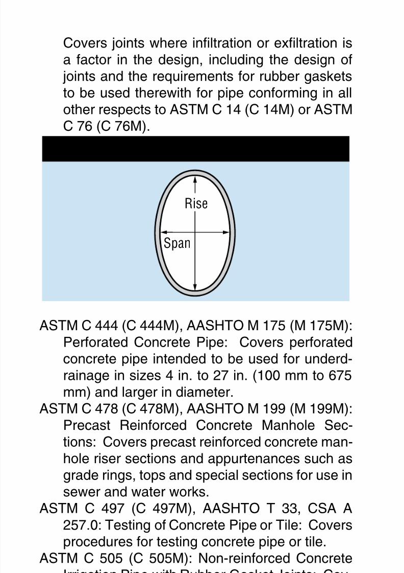
8/7/2019 Concrete Pipe - Installation Guide
http://slidepdf.com/reader/full/concrete-pipe-installation-guide 83/91
American Concrete Pipe Association • www.concrete-pipe.org 83
including hydraulic transients, of up to 30 ft. (9m) of head. Higher pressures may be used upto a maximum of 50 ft. for 6 in. to 12 in. (15
m for 150 mm to 300 mm) in diameter, and 40ft. for 15 in. to 18 in. (12 m for 375 mm to 450mm) in diameter by increasing the strength ofthe pipe.
ASTM C 506 (C 506M), AASHTO M 206 (M 206M):Reinforced Concrete Arch Culvert, Storm Drainand Sewer Pipe: Covers arch pipe in threestrength classes in sizes from 15 in. to 132 in.(375 mm to 3300 mm) in equivalent circular di-ameter based on periphery. Larger sizes areavailable as special designs.
ASTM C 507 (C 507M), AASHTO M 207 (M 207M):Reinforced Concrete Elliptical Culvert, StormDrain and Sewer Pipe: Covers reinforced el-liptically shaped concrete pipe. Five standardclasses of horizontal elliptical, 18 in. to 144in. (450 mm to 3600 mm) in diameter and vestandard classes of vertical elliptical, 36 in. to144 in. (900 mm to 3600 mm) in diameter areincluded. Equivalent circular sizes are basedon cross-sectional area. Larger sizes are avail-able as special designs.
ASTM C 655 (C 655M), AASHTO M 242 (M 242M):Reinforced D-Load Culvert, Storm Drain and
ARCH PIPE
SpanRise

8/7/2019 Concrete Pipe - Installation Guide
http://slidepdf.com/reader/full/concrete-pipe-installation-guide 84/91
American Concrete Pipe Association • www.concrete-pipe.org84
Sewer Pipe: Covers acceptance of pipe designand production pipe based upon the D-loadconcept and statistical sampling techniques for
concrete pipe to be used for the conveyance ofsewage, industrial waste and storm water andconstruction of culverts.
ASTM C 822 (C 822M), AASHTO M 262 (M 262M):Denition of Terms Relating to Concrete Pipeand Related Products: Includes denitions forwords and terms occurring in concrete pipestandards.
AASTM C 877 (C 877M): External Sealing Bandsfor Noncircular Concrete Sewer, Storm Drainand Culvert Pipe: Covers external sealingbands for noncircular concrete pipe conformingto ASTM C 506 (C 506M), C 507 (C 507M), C1433 (C 1433M), C 1504 (C 1504M), C 1577(C 1577M).
ASTM C 923 (C 923M): Resilient Connectors Be-tween Reinforced Concrete Manhole Structuresand Pipes: Covers the minimum performanceand material requirements for resilient connec-tions between pipe and reinforced concretemanholes conforming to ASTM C 478M (C478).
ASTM C 924 (C 924M): Testing Concrete PipeSewer Lines by Low-Pressure Air Test Method:Covers procedures for testing concrete pipesewer lines by low-pressure air test to demon-strate the integrity of the installed material andthe construction procedures.
ASTM C 969 (C 969M): Practice for Inltration andExltration Acceptance Testing of Installed Pre-cast Concrete Pipe Sewer Lines: Covers pro-cedures for testing installed precast concretepipe sewer lines using either water inltration
8/7/2019 Concrete Pipe - Installation Guide
http://slidepdf.com/reader/full/concrete-pipe-installation-guide 85/91
American Concrete Pipe Association • www.concrete-pipe.org 85
or exltration acceptance limits to demonstratethe integrity of the installed materials and con-struction procedures.
ASTM C 985 (C 985M): Non-reinforced ConcreteSpecied Strength Culvert Storm Drain, andSewer Pipe: Covers non-reinforced concretepipe designed for specied strengths and in-tended to be used for the conveyance of sew-age, industrial wastes, and storm water and forthe construction of culverts.
ASTM C 990 (C 990M): Specication for Joints forConcrete Pipe, Manholes, and Precast BoxSections Using Preformed Flexible Joint Seal-ants: Covers joints for precast concrete pipeand box, and other sections using preformedexible joint sealants for use in storm sewersand culverts which are not intended to operateunder internal pressure, or are not subject toinltration or exltration limits.
ASTM C 1103 (C 1103M): Practice for Joint Accep-tance Testing of Installed Precast ConcretePipe Sewer Lines: Covers procedures for test-ing the joints of installed precast concrete pipesewer lines, when using either air or water un-der low pressure to demonstrate the integrity ofthe joint and the construction procedures.
ASTM C 1214 (C 1214M): Test Method for Con-crete Pipe Sewer Lines by Negative Air Pres-
sure (Vacuum) Test Method: Covers using thenegative air pressure test for 4 in. to 36 in. (100mm to 900 mm) in diameter circular concretepipe sewer lines utilizing gasketed joints.
ASTM C 1244 (C 1244M): Standard Test Methodfor Concrete Sewer Manholes by the Negative
Air Pressure (Vacuum) Test Method: Coversusing the negative air pressure test for concretesewer manholes utilizing gasketed joints.
8/7/2019 Concrete Pipe - Installation Guide
http://slidepdf.com/reader/full/concrete-pipe-installation-guide 86/91
American Concrete Pipe Association • www.concrete-pipe.org86
ASTM C 1433 (C 1433M): Precast Reinforced Con-crete Box Sections for Culverts, Storm Drains,and Sewers: Covers single-cell reinforced con-
crete box sections intended to be used for theconstruction of culverts and for the conveyanceof storm water industrial wastes and sewage.
ASTM C 1479: Standard Practice for Installation ofPrecast Concrete Sewer, Storm Drain, and Cul-vert Pipe Using Standard Installations: coversthe installation of precast concrete pipe intend-ed to be used for the conveyance of sewage,industrial wastes, and storm water and for theconstruction of culverts.
ASTM C 1577 (C 1577M): Precast Reinforced Con-crete Box Sections for Culverts, Storm Drains,and Sewers Designed According to AASHTOLRFD: Covers single-cell precast reinforcedconcrete box sections intended to be used forthe construction of culverts, and for the convey-ance of storm water, industrial wastes and sew-age.
ASTM C 1619: Standard Specication for Elasto-meric Seals for Joining Concrete Structures:covers the physical property requirements ofelastromeric seals (gaskets) used to seal thejoint of precast concrete structures conform-ing to specications C 14 (C 14M), C 118 (C118M), C 361 (C 361M), C 443 (C 443M) orC 505 (C 505M) used in gravity and low headpressure applications.
AASTM C 1628: Standard Specications for Jointsfor Concrete Gravity Flow Sewer Pipe, UsingRubber Gaskets: covers exible leak resistancejoints for concrete gravity ow sewer pipe us-ing rubber gaskets for sealing the joints, wheremeasurable or dened inltration or exltrationis a factor of the design.
8/7/2019 Concrete Pipe - Installation Guide
http://slidepdf.com/reader/full/concrete-pipe-installation-guide 87/91
American Concrete Pipe Association • www.concrete-pipe.org 87
IV.APPENDIX
DEFINITIONS
BackllorSideFill: the layer of soil placed aroundor above the pipe or box unit.
Bedding: the material used to cushion and evenlydistribute the soil reaction at the bottom of thestructure.
BellEnd: that portion of the end of the pipe or box
unit, regardless of its shape or dimensions,which overlaps a portion of the end of the ad-joining pipe or box culvert.
BoxCulvert/Section: A culvert with a rectangularcross section
Concrete: a homogeneous mixture of Portland ce-
ment, ne aggregate, coarse aggregate, andwater. The mixture may also contain admix-tures, or other cementitious materials, or both.
Culvert: a pipeline or box intended to convey wa-ter under a highway, railroad, canal, or similarfacility.
ExternalSealingBands: exible wrappings thatare applied to the outside of a concrete pipe,box section, or manhole section joint intend-ed to control the movement of uids or solidsthrough the joint.
Gradation: the distribution of particles of granu-lar material among standard sizes usually ex-pressed in terms of cumulative percentageslarger or smaller than each of a series of sieveopenings.
HandlingReinforcement: reinforcement intendedto reduce the risk of collapse of the pipe or sec-tion during handling or storage prior to and dur-ing nal placement.
Inltration: the volume of groundwater entering a
8/7/2019 Concrete Pipe - Installation Guide
http://slidepdf.com/reader/full/concrete-pipe-installation-guide 88/91
American Concrete Pipe Association • www.concrete-pipe.org88
sewer and its connections through pipe, boxes,joints, connections or appurtenances.
InstalledLength: nal length, along the centerline,
of a pipe or box section in place including thelongitudinal joint separation between the sec-tion and the last section placed.
Invert: the bottom or lowest point of the internal sur-face of the transverse cross section of a pipe.
Joint: a connection of two pipe, manhole, or boxsection ends, made either with or without theuse of additional parts and/or materials.
LiftHole: a small hole cast or drilled in the wall ofthe pipe or section for inserting a bolt, loop ofcable or other device used in handling the pipeor section.
Lot:an assemblage of concrete pipe or box culverts,all being of like size, material, and strength des-ignation, manufactured by the same process.The lot size may differ from the quantity desig-nated in the contract or order.
Manhole: a Precast concrete structure for verticalaccess to a pipeline or other closed structure.
O-Ring Gasket: a solid gasket of circular crosssection that is recessed in a groove on the pipetongue or spigot and then conned by the bellor groove after the joint is completed.
Permeability: that property which permits move-ment of a liquid through the pores and interstic-es of the concrete
Pipe: a tube or elongated hollow concrete structureintended to transmit ow between locations.
PipeDiameter: the inside diameter of a concretepipe
PipeSection: a single pipe.
Pipeline: pipe sections joined together.PreformedFlexibleJointSealant: pliable mate-
8/7/2019 Concrete Pipe - Installation Guide
http://slidepdf.com/reader/full/concrete-pipe-installation-guide 89/91
American Concrete Pipe Association • www.concrete-pipe.org 89
rial formed into a dened cross section that isapplied to the surface of a pipe, box section, ormanhole section joint, intended to control the
movement of uids or solids through the joint.ReinforcedConcretePipe: a pipe structure com-prised of concrete and steel reinforcement.Such reinforcement is comprised of steel wire,welded wire fabric, or bars, of known strength,formed into a cage and positioned in the con-crete wall in a specic location in such a man-ner that the two materials act together to resiststresses.
Reinforcement: steel in the form of wire, weldedwire fabric, or bars embedded in concrete insuch a manner that the above referenced con-crete and steel act together to resist stresses.
ResilientConnector: a exible connection for join-ing pipe to structures capable of being deformedand deected without rupture or leakage.
RubberGasket: rubber formed and used as a sealin concrete pipe joints.
Spigot: that portion of the end of the pipe, regard-less of its shape or dimensions, which is over-lapped by a portion of the end of the adjoiningpipe.
Springline: the points on the internal surface of thetransverse cross section of a pipe intersectedby the line of maximum horizontal dimension;or in box sections, the mid-height of the internalvertical wall.
Watertight: will restrain the passage of water to notexceed a specied limit.
8/7/2019 Concrete Pipe - Installation Guide
http://slidepdf.com/reader/full/concrete-pipe-installation-guide 90/91
American Concrete Pipe Association • www.concrete-pipe.org90
Feet Lbs. perHead Square Inch FeetHead kPa
1 .43
2 .87
3 1.30
4 1.73
5 2.17
6 2.60
7 3.038 3.40
9 3.90
10 4.33
15 6.50
20 8.66
25 10.83
30 12.99
35 15.16
40 17.3245 19.40
50 21.65
55 23.82
60 25.99
65 28.15
70 30.32
75 32.48
80 34.65
85 36.81
90 38.98
95 41.14
100 43.31
110 47.64
120 51.97
130 56.30
140 60.63
150 64.96160 69.29
170 73.63
180 77.96
190 82.29
200 86.62
225 97.45
250 108.27
275 119.10
300 129.93325 140.75
350 151.58
1 2.99
2 5.98
3 8.96
4 11.95
5 14.94
6 17.93
7 20.928 23.91
9 26.90
10 29.89
15 44.83
20 59.77
25 74.71
30 89.66
35 104.60
40 119.5445 134.48
50 149.43
55 164.37
60 179.31
65 194.25
70 209.20
75 224.14
80 239.08
85 254.02
90 268.97
95 283.91
100 298.85
110 328.73
120 358.62
130 388.51
140 418.39
150 448.28160 478.16
170 508.05
180 537.93
190 567.81
200 597.70
225 672.41
250 747.13
275 821.84
300 896.55325 971.26
350 1046.00
FEET HEAD OF WATERINTO PRESSURE, POUNDS
PER SQUARE INCH
FEET HEAD OF WATERINTO KILOPASCALS
(kN/m2)
8/7/2019 Concrete Pipe - Installation Guide
http://slidepdf.com/reader/full/concrete-pipe-installation-guide 91/91
1303 West Walnut Hill Lane Suite 305