conceptual design study of a closed brayton cycle ... · conceptual design study of a closed...
TRANSCRIPT

EDR 90258
Conceptual Design Study Of A Closed Brayton
Cycle Turbogenerator For Space Power Thermal-To-Electric Conversion System
Final Report
Jeff L. Hansen
Allison Advanced Development Company
Indianapolis, Indiana
November 2000
Prepared For
Marshall Space Flight CenterUnder Order No. H31376D
https://ntrs.nasa.gov/search.jsp?R=20000120035 2020-04-21T08:20:52+00:00Z


EDR 90258
Conceptual Design Study Of A Closed Brayton
Cycle Turbogenerator For Space Power Thermal-To-Electric Conversion System
Final Report
Jeff L. Hansen
Allison Advanced Development Company
Indianapolis, Indiana
November 2000
Prepared For
Marshall Space Flight Center
Under Order No. H31376D


1.0
2.0
3.0
Summary .................................................................................................................. 1
Introduction ............................................................................................................. 3
Overview of Turbogenerator System Trade Study .............................................. 5
He-Xe working Fluid ................................................................................................. 5
Number of Engine Shafts and Mode of Operation .................................................... 6
Cycle Pressure Ratio ................................................................................................. 6
Compressor Configuration ....................................................................................... 6
Turbine Inlet Temperature ........................................................................................ 7
Oil Bearinqs .............................................................................................................. 8
Generator Type ......................................................................................................... 8
Regenerator (Optional) ............................................................................................. 8
4.0 Description of Selected Turbogenerator Configuration ...................................... 9
4.1 Compression System .................................................................................................... 9
4.2 Turbine System .......................................................................................................... 11
4.3 Shaft Dynamics .......................................................................................................... 12
4.4 Bearings and Seals ..................................................................................................... 124.5 Generator and Power Control Electronics ................................................................. 14
Hybrid Homopolar .................................................................................................. 15
Permanent Magnet (PM) ......................................................................................... 15A C Induction Machine ............................................................................................ 15
Axial Gap Permanent Magnet Machine .................................................................. 15
4.6 System Physical Characteristics ................................................................................. 16
4.7 System Life ................................................................................................................ 17
4.8 Regenerator System (Optional) .................................................................................. 17
Regenerators vs. Recuperators ............................................................................... 19
5.0 Program Risks ....................................................................................................... 21
(1) Gas Bearings ..................................................................................................... 21
(2) Turbine Efficiency. ............................................................................................. 21
(3) High Speed Generator ....................................................................................... 21
(4) He-Xe Working fluid .......................................................................................... 21
(5) Regenerator Disks and Seals ............................................................................. 22
6.0 Development Schedule and Cost .......................................................................... 23
Option 1: Regenerator Study .................................................................................. 23
Option 2: Reduced Generator Development Effort ................................................. 23
Option 3: Magnetic Bearings .................................................................................. 23
7.0 Conclusion .............................................................................................................. 27
-- i

EDR 90258
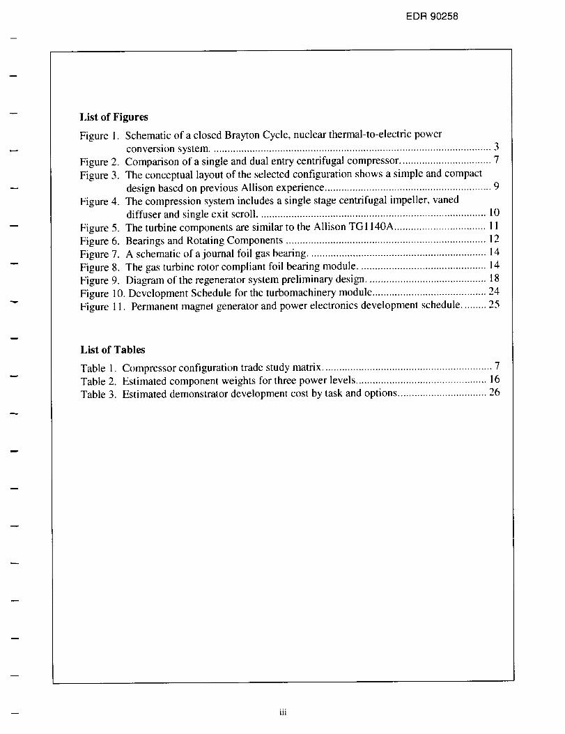
List of Figures
Figure
Figure 2.
Figure 3.
Figure 4.
Figure
Figure
Figure
Figure
Figure
Figure
Figure
1. Schematic of a closed Brayton Cycle, nuclear thermal-to-electric power
conversion system ..................................................................................................... 3
Comparison of a single and dual entry centrifugal compressor ................................. 7
The conceptual layout of the selected configuration shows a simple and compact
design based on previous Allison experience ............................................................ 9
The compression system includes a single stage centrifugal impeller, vaned
diffuser and single exit scroll .................................................................................. 10
5. The turbine components are similar to the Allison TG1140A ................................. 11
6. Bearings and Rotating Components ........................................................................ 12
7. A schematic of a journal foil gas bearing ................................................................ 14
8. The gas turbine rotor compliant foil bearing module .............................................. 14
9. Diagram of the regenerator system preliminary design ........................................... 18
10. Development Schedule for the turbomachinery module ......................................... 24
11. Permanent magnet generator and power electronics development schedule ......... 25
List of Tables
Table 1.
Table 2.
Table 3.
Compressor configuration trade study matrix ............................................................. 7
Estimated component weights for three power levels ............................................... 16
Estimated demonstrator development cost by task and options ................................ 26
-- iii


EDR 90258
1.0 Summary
A conceptual design study was completed for a 360kW Helium-Xenon closed Brayton cycle
turbogenerator. The selected configuration is comprised of a single-shaft gas turbine engine
coupled directly to a high-speed generator. The engine turbomachinery includes a 2.5:1
pressure ratio compression system with an inlet corrected flow of 0.44 Kg/sec. The single
centrifugal stage impeller discharges into a scroll via a vaned diffuser. The scroll routes the air
into the cold side sector of the recuperator. The hot gas exits a nuclear reactor radiator at
1300°K and enters the turbine via a single-vaned scroll. The hot gases are expanded through
the turbine and then diffused before entering the hot side sector of the recuperator. The single
shaft design is supported by air bearings. The high efficiency shaft mounted permanent
magnet generator produces an output of 370 kW at a speed of 60,000 rpm. The total weight of
the turbogenerator is estimated to be only 123 Kg (less than 5% of the total power plant) and
has a volume of approximately 0.11 m 3. This turbogenerator is a key element in achieving the
40 to 45% overall power plant thermal efficiency.
m 1


EDR 90258
2.0 Introduction
Under Order No. H31376D to NASA MSFC, Allison Advanced Development Company
(AADC) conducted a conceptual design study of a Helium-Xenon closed Brayton cycle
turbogenerator for a nuclear thermal-to-electric power conversion system.
A commercial need for a space vehicle that serves as a satellite 'tug boat' has been identified.
This vehicle would retrieve satellites in need of repair from high earth orbit to rendezvous
with a shuttle in low earth orbit and ferry satellites from the shuttle to high orbits. This
vehicle could also be used to reposition satellites to their proper or alternate positions.
Additionally, numerous civilian space missions would be enhanced or enabled by electric
propulsion system in the 50 to 4000 kWe range.
The requirement for the propulsion system of such a vehicle is to provide full power
continuously for more than three years without refueling. A candidate electrical power source
is a closed Brayton cycle nuclear thermal-to-electric conversion system. The main
components of this system consist of a nuclear reactor, gas turbine engine, generator,
recuperator and radiator. A schematic of this type of system is illustrated in Figure 1.
NUCLEAR REACTOR
HEAT i
[ COMPRESSOR I
IG II II II.... I
RATOR
DUCTING
Figure 1. Schematic of a closed Brayton Cycle, thermal-to-electric power conversion system.
-- 3

Allison Advanced Development Company
The focus of this study is the feasibility of turbogenerator portion of this power conversion
system. The turbogenerator components are highlighted in Figure 1 and consist of a
compressor, turbine, generator and power electronics.
The preliminary design of these components was based on existing, modified, and new
turbogenerator components using results from previous research and development programs.
The following studies were undertaken as part of this activity.
• Development of a preliminary configuration layout of the options which best satisfy the
requirements based on trade-off studies,
• Definition of subsystems to be designed and/or procured,
• Identification of potential areas of risk,
• Define a development schedule including rough order of magnitude cost to demonstrate a
turbogenerator system.
This report summarizes the results of the preliminary design activity.
4

EDR 90258
3.0 Overview of Turbogenerator System Trade Study
AADC conducted a preliminary design trade study to determine the feasibility of a closed
Brayton cycle turbogenerator for space power. The information resulting from this exercise
provides an early indication of technical and program risks prior to committing to a detailed
design and development program.
The study was initiated by identifying a baseline turbogenerator configuration, based primarily
on Allison's TG1140A turbogenerator system. All aspects of the turbogenerator system were
considered, with the following primary trades being discussed in more detail in subsequent
sections of this report:
• He-Xe working fluid vs. air
• l-shaft vs. 2-shaft turbine system
• compression ratio
• compressor configuration
• turbine inlet temperature
• gas bearings vs. oil bearings
• generator type
• regenerator vs. recuperator heat recovery system
The design state point conditions for a 360kW Brayton power system was provided by NASA
MSFC. The cycle model was set up assuming a turbine inlet temperature of 1300°K and 2.0:1
cycle pressure ratio. Using this cycle data, baseline engine component sizes were estimated,
from which a configuration layout drawing was generated. From this layout, preliminary
weight and cost estimates were established. A preliminary generator specification was also
created and provided to vendors to supply cost and performance information. Various
alternatives to the baseline configuration were also considered. Decisions made when
evaluating those options are discussed in the following paragraphs.
He-Xe working Fluid
The use of a working fluid other than air in a gas turbine engine is not standard practice at
AADC and adds an element of risk to a development program. However, inert gases such as
Helium have been used in closed systems and AADC has had some experience with
preliminary designs of such systems. All of AADC's aerodynamic design and analysis tools
have the capability of inputting any gas properties minimizing this risk. In addition, the
mixture of 70% Helium and 30% Xenon has pertinent property values, such as density, similar
to air.
-- 5

AllisonAdvancedDevelopmentCompany
Number o( Engine Shafts and Mode of Operation
The selection of an engine configuration in terms of number of shafts and operating mode is
almost entirely dictated by the intended application of the system. Since the operating power
range of this application is expected to be near 100% output at all times, the best
turbogenerator configuration is the single shaft, constant speed engine configuration. This
configuration is commonly used in APU's, industrial and marine applications, and some
turboprop aircraft applications. The simplicity of this configuration yields the lowest system
part count and lowest system weight and cost. Two-shaft configurations cannot match the
design point efficiency of the single shaft system because of added bearing and turbine
transition duct losses. In addition, operation of a single shaft system in constant speed mode
provides the best transient response to load demands of any turbine system.
Cycle Pressure Ratio
Unlike simple gas turbine cycles, where higher pressure ratio yields better fuel efficiency,
optimum cycle pressure ratio for regenerative cycles is typically less than 3.5. The
preliminary design study looked at compressor pressure ratios ranging from 1.9 to 3.0. The
results of this study indicate that a pressure ratio of 2.5 is a good compromise between thermal
efficiency and matching the turbomachinery with a direct drive high-speed generator.
Compressor Configuration
A preliminary design trade study was conducted on a matrix of design parameters consisting
of pressure ratio, shaft speed, inlet pressure and entry type. This study was completed to
explore the levels of compromise required between the compressor, turbine and generator.
The matrix of compressor configurations examined is provided in Table 1 along with the
estimated efficiency for each. The chosen configuration has a single entry and produces 2.5
pressure ratio at 60,000 rpm. This design also has the highest efficiency of those studied with
a polytropic efficiency of 84.0%.
A dual entry configuration was considered because the specific speed is very high at 60,000
rpm and pressure ratio of only 2.0. The dual entry configuration lowers the specific speed and
raises the efficiency significantly as shown in Table 1. A dual entry compressor also has a
smaller diameter than single entry. However, the added complexity of the impeller and inlet
system is a disadvantage and should be avoided if possible. A comparison of the dual entry
configuration (2) and the single entry configuration (3) is shown in Figure 1.
6

EDR 90258
Table 1. Compressor configuration trade stud's' matrix.
ClP = 1.5 MPa
Poly. Dia.
Pr rpm Eft. inches
2.0 60,000 Base 8.5
2.0 60,000 +3.4% 8.0
2.5 60,000 +4.5% 9.2
2.0 50,000 +3.7% 9.7
Confi_l. Entry
1 Single
2 Dual
3 Single
4 Single
5 Single
6 Dual
7 Single
8 Single
ClP = 0.75 MPa
2.0 60,000 -2.5% 10.4
2.0 60,000 +2.8% 9.5
3.0 60,000 +4.3% 10.9
2.0 45,000 +3.3% 12.1
cL
F-
SJf
Single Entry Dual Entry
Figure 2. Comparison of a single and dual entry centrifugal compressor.
Turbine Inlet Temperature
It is realized that maximum thermal efficiency is obtained at higher turbine inlet temperatures.
However, higher temperatures negatively impact turbine life. From AADC's experience, it is
-- 7

AllisonAdvancedDevelopmentCompany
known that an increase of 20°K can reduce turbine life by as much as 50%. Preliminary
analysis indicates that the desired life of 30,000 hours is achievable at 1300°K with
conventional turbine materials.
Oil Bearinqs
Oil beatings offer low risk in terms of bearing development as they are widely used in all
current Allison production engines. However, the use of oil bearings requires additional
hardware in the form of an oil pump, oil tank, fluid lines, and oil cooler. The cost and
maintenance associated with these items is eliminated by using gas beatings. Additionally, the
lubrication system requires maintenance that is not feasible in a space-deployed system.
Consequently, oil bearings were not considered a viable option. The benefits and risks of gas
bearings are further discussed in more detail in Section 3.4.
Generator Type
As discussed in Section 4.5, several high-speed generator design approaches were considered.
At this time, a permanent magnet generator has been selected as the preferred generator type
for this application. This selection is based on the recommendations of Ashman Technologies,
a high-speed generator supplier. The permanent magnet generator is a compact design with
efficiencies greater than 92% achievable.
Regenerator (Optional)
Regenerators offer similar performance advantages as fixed recuperators, but are substantially
smaller and lighter, with initial costs estimated to be less than a comparable recuperator
system. A feasibility study of the use of a regenerator in a space power system is not part of
the work scope for this program. However, the benefits of a regenerator over a recuperator are
potentially very high, but at a higher risk, and should be considered during a detailed design
phase. A more detailed description of a regenerator system is contained in Section 4.8.

EDR 90258
4.0 Description of Selected Turbogenerator Configuration
After evaluating the performance and costs of the baseline configurations and the alternative
configurations, Allison selected a turbogenerator configuration that would provide the lowest
risk to NASA. A conceptual layout of the selected turbogenerator system is shown in Figure 3.
The turbogenerator is comprised of a single-shaft gas turbine engine coupled directly to a
high-speed generator. The generator is mounted ahead of the power section inlet to minimize
operating and soakback temperatures for improved efficiency and reliability. The generator
employs a permanent magnet rotor with a high strength casing to allow continuous high-speed
operation. The generator serves as a starter motor in addition to providing electrical power.
Generator
CompressorTurbine
Figure 3. The conceptual layout of the selected configuration shows a simple and compact
design based on previous Allison experience.
The engine turbomachinery includes a 2.5:1 pressure ratio compression system. The efficient
single centrifugal stage impeller discharges into a scroll via a vaned diffuser. The scroll routes
the air into the cold side sector of the recuperator.
The hot gas exits the nuclear reactor radiator and enters the turbine via a single-vaned scroll.
The hot gases are expanded through the turbine and then diffused before entering the hot side
sector of the recuperator
The single shaft design is supported by air bearings, which eliminates standard lubrication
system servicing and reduces system cost. Fixed geometry components are used for simplicity
and any required engine cooling is provided internally using compressor discharge air.
4.1 Compression System
Preliminary sizing of the compressor section was performed based on the air flow and
pressure ratio requirements of the engine as identified by the preliminary performance cycle
9

Allison Advanced Development Company
from NASA. Corrected airflow at the design condition is 0.44 Kg/sec at a pressure ratio of
2.5:1. Compressor polytropic efficiency is predicted to be 84%. AADC's compressor
aerodynamic design and development experience coupled with the use of advanced fluid
dynamic design tools, including 3-D, viscous codes, will facilitate the development effort,
enabling these goals to be realized.
The preliminary design of the compressor section is based on a combination of Allison
automotive and aircraft engine experience with designs of this general size. The compression
system, shown in Figure 4, is comprised of a single-stage centrifugal impeller with a vaned
diffuser and single exit scroll. The impeller design includes a combination of both full and
partial blades for optimum aerodynamic performance. The modular scroll section collects and
routes the compressor discharge air through a single exit to be ducted to the recuperator.
Figure 4. The compression system includes a single stage centrifugal impeller, vaned diffuser
and single exit scroll.
The preliminary performance analysis predicts compressor flowpath temperatures suitable to
allow the use of stainless steel in the impeller design. Impellers of this size are typically
machined to achieve the thinner airfoils and smaller fillet radii necessary to obtain the
aerodynamic performance goals. This is important since compressor efficiency has a
significant impact on engine efficiency. Final material selection will be based on detailed
stress analysis of each component with emphasis on system integrity.
The preliminary design of the compressor assembly is similar to that used in the Allison
TG 1140A. This configuration provides easy assembly and installation of compressor
components for inexpensive manufacturing and assembly. Given the positive aspects of this
configuration, Allison was unable to identify any additional improvements or design features
1o

EDR 90258
during the preliminary design phase.
4.2 Turbine System
The turbine system is comprised of an inlet volute and guide vanes, an integrally cast single
stage turbine, and a turbine diffuser exhaust duct and is shown in Figure 5. The turbine design
was a 110% scale from Allison's TG 1140A Hybrid automotive turbogenerator. The turbine
adiabatic efficiency is expected to be 81%. This low efficiency is attributed to the small size
effects including large losses associated with blade tip clearances. The assumed tip clearance
may be reduced significantly since operating transients are not an issue for this application.
Since the turbogenerator operates at a constant speed and does not require a quick start-up, the
running blade tip clearances can be reduced from typical gas turbine engine applications. An
increase of 2 to 3% may be realized during the detailed design phase.
The axial turbine blisk is planned to be cast of MAR-M247 and inertia welded to a 410 SS
shaft that ties the turbine, compressor, and bearing journal together. Air pulled from the
compressor will cool the air bearings and the turbine. The amount of flow is controlled by
either a single seal or flow restrictor.
Figure 5. The turbine components are similar to the Allison TG1140A.
The axial inlet volute preliminary design was scaled from the Hybrid design that used a 3-D
CFD (computational fluid dynamic) solution to set the guide vane span for 20 vanes. The
predicted total pressure losses were 1.5% for the bend and volute and 5.3% for the vanes.
Effort will be made during the detailed design phase to further reduce these losses. This may
be possible since the Hybrid design was somewhat compromised by packaging constraints
specific to that application. The volute may also be changed to gain fabrication advantages
with relaxed space constraints. The axial inlet volute is supported to the bearing housing
-- 11

AllisonAdvancedDevelopmentCompany
(similar to theTG1140A)to reducestressandallow for relativethermalexpansion.
ThepreliminarydiffuserwasalsoscaledfromtheTG1140Adesign,but will likely bechangedin thefinal designto betterdirect theflow throughasingleexit collectorto ductthehot gasto therecuperator.
As ceramictechnologyis developed,asingleaxialceramicturbinemaybeconsideredforfuturedesignimprovements.Ceramictechnologywouldprovidesignificantincreasesto bothpowerandthermalefficiencyfrom thesamepackagesizewithoutimpactingturbinelife.
4.3 Shaft Dynamics
The turbogenerator shaft design is based on that used in the Allison TG1140A engine, and
incorporates improvements from experience with that engine to improve reliability and
maintainability. The power core rotor consists of a radial compressor and an axial turbine
cantilevered from a bearing module. The three components, including the bearing module, are
bolted together with a central tie shaft. The turbine and generator rotor systems preliminary
designs are shown in Figure 6. They are coupled together by a flexible coupling shaft that
transfers torque but is soft laterally and decouples the two rotors dynamically.
Figure 6. Bearings and Rotating Components
4.4 Bearings and Seals
For the unique space application of this turbogenerator, it is a requirement to eliminate all
short-term (less than 30,000 hours) maintenance needs of typical gas turbine engines. For this
reason, gas bearings were chosen over either rolling element or hydrodynamic oil journal
bearings to eliminate the need for an oil lubrication system, oil dependent bearings and air/oilseals.
Hydrodynamic air bearings were selected over hydrostatic air beatings because they require
12

EDR 90258
only the surrounding ambient air and not a high pressure air supply. Compliant foil gas
bearings (CFB) were chosen because they proved robust in rotor shaft rig testing at Allison.
The particular reversed multi-layered design made by R&D Dynamics was chosen for best
rotor stability and damping because of higher hysterisis damping. Allison has worked with
R&D Dynamics to develop a compliant foil bearing for turbine applications to be as
successful as they have been for air cycle machines. In addition, on going gas bearing
research at NASA GRC will be utilized during detailed design to achieve the most reliable
and lowest risk configuration.
Gas bearing foils separate from the shaft due to self-generated pressures and become fully
supported on a cushion of air at about 1500 rpm. The stiffness of the gas film cushion
continues to increase with speed until the gas film is quite stiff at the highest speed. At this
point, the beating load capacity is typically 50 pounds per square inch of proiected journal
area. The dynamic stiffness and damping of the foil bearing is controlled by the corrugated
foil in series with the stiffer gas film. Two adjacent smooth foils, wrapped in opposite
directions, move relative to the corrugated foil producing additional coulomb damping for
rotor stability.
Foil gas bearings offer the following advantages:
• Reliability is improved because there are fewer parts needed to support the rotating
assembly and the foil touches the shaft only when the machine starts and stops.
• Operating efficiency is maintained at high and low temperatures where other bearings are
no longer effective.
• Efficiency is improved with less parasitic losses at high speed.
The compressor and turbine are both overhung with two CFB journals between. A foil gas
thrust bearing is nearest the compressor to control axial tip clearances. This same thrust
bearing also supports the generator axial loads through the flexible shaft coupling. The journal
air bearing, shown in Figure 7, is a unique, reversed multi-layered design that maximizes
damping for a more stable rotor system. Bearings of this design are used in many air cycle
machines for commercial aircraft, such as the 747, where mean times between failures of
100,000 hours have been demonstrated. The turbine rotor compliant foil bearing module is
shown in Figure 8.
13

Allison Advanced Development Company
Figure 7. A schematic of a journal foil gas bearing.
Figure 8. The gas turbine rotor compliant foil bearing module.
This design requires only one seal to restrict airflow between the compressor and turbine. This
lab seal on the outside diameter of the thrust disk also provides some thrust balance to reduce
bearing thrust loads. This seal is included in the bearing module and allows some cooling air
down the shaft to cool the bearings and turbine rotor.
4.5 Generator and Power Control Electronics
The shaft-mounted generator system, which includes the starter/generator, control unit, and
associated interconnecting cables and connectors, provides several functions. The
starter/generator is capable of converting stored electrical energy into rotational mechanical
14

EDR 90258
energy for purposes of starting the gas turbine engine. Once the engine is capable of producing
net power, the electronic control switches the system into generate mode where rotational
mechanical energy is converted into electrical power.
Through the efforts of previous programs, Allison has experience with various generator
suppliers and types. All of these machines have favorable attributes and require further in-
depth analysis before a final selection is made. Allison's previous experience with high-speed
generators suggests that it might be advisable to have two generator suppliers during the
development phase to minimize program risk. The generator options under consideration are
discussed briefly in the following text:
Hybrid Homopolar
Allison currently has experience with this type of design on the TG1140A. The design
combines a permanent magnet and homopolar design into one machine. The advantage of this
design is that voltage can be varied at any speed by bucking or boosting the flux using the
homopolar portion of the control. The primary disadvantage of this type of design is that the
machine is larger than a pure permanent magnet machine and the air gaps are small in the
homopolar flux return path. This machine would be considered to have moderate risk for high
operating speeds. However, since the generator for space-power is essentially a constant
speed generator, the advantage of this design is minimized.
Permanent Magnet (PM)
This design is significantly smaller than the Hybrid Homopolar and has been successfully
used in several high-speed applications. The predicted efficiency for the machine and
controller electronics is greater than 90%.
A C Induction Machine
This design is the largest of those evaluated. The efficiency is predicted to be comparable to
the PM design. The AC induction machine will likely have the highest reliability and lowest
production cost of those evaluated. Given the current state of development, Allison considers
this design to have the lowest risk.
Axial Gap Permanent Magnet Machine
This design has been under development in England at the Imperial College for many years.
The primary advantage of this design is that the magnet retention does not add to the air gap
and stator iron losses are reduced. High-speed prototypes have been built and operated with
one or two axial components. More axial components can be added for additional power.
Allison considers the risk of this machine low, but requires more knowledge concerning
development costs.
15

Allison Advanced Development Company
A permanent magnet generator was selected for the baseline configuration since Allison has
experience with the PM design. In addition, a PM supplier, Ashman Technologies, was
recommended by NASA. In start mode, the power control electronics converts DC power
from the battery pack to current regulated, variable frequency, phased AC power to the PM
motor which in turn generates torque on the engine shaft. In power generation mode, three-
phase, variable voltage, variable frequency power from the generator is converted to DC
power. The basic requirements of the generator and power conditioning unit supplied to
Ashman Technologies for preliminary sizing is listed below.
• Generator output:
• Speed:
• Power electronics output:
• Power and DC bus Voltages:
• Overall efficiency:
• Operational Life:
370 kW
60,000 rpm
360 kW
1-3% 28 VDC (space bus power)
2-4% 130 VDC (avionics grade)
90-95% 1300 VDC (non-avionics grade)
92% minimum at 360 kW
3-5 years continuous
4.6 System Physical Characteristics
Preliminary analysis indicates that the 360 kW turbogenerator system weighs approximately
135 Kg. This estimate includes the components shown in Figure 3 plus associated power
control electronics. A breakdown of weights by component is shown in Table 2. This table
also shows the estimated weight and volume for a turbogenerator scaled to 100 kW and 1000
kW. During the detailed design, AADC will attempt to reduce system weight whenever
possible without compromising system performance, or reliability. Thus, actual weight may be
greater than or less than this estimate as design choices are made in the detailed design phase.
Table 2. Estimated component weights for three power levels.
Power Output
Module
TurbomachineryGeneratorPower Electronics
1 O0 kW
Wt. (Kg) VOI. (m 3)12 0.01315 0.00918 0.017
360 kW
Wt. (Kg) Vol. (m 3)25 0.03747 0.01662 0.054
1000 kW
Wt.(Kg) Vol.(m 3)80 0.16570 0.02487 0.076
Total 45 0.039 123 0.107 237 0.265
16

EDR 90258
4.7 System Life
The preliminary assessment of the turbogenerator indicates the required life of greater than
30,000 hours with no maintenance is achievable. The primary features that contribute to the
system long life compared to conventional land based turbogenerators include:
• The replacement of oil bearings and lube system with gas bearings
• Particle free working fluid prevents erosion of compressor and turbine airfoils
• Moderate turbine inlet temperature allows use of production high temperature super alloys
4.8 Regenerator System (Optional)
Regenerators are rotating heat recovery devices which transfer the energy from hot turbine
exhaust gas (which would otherwise be wasted) to heat the air which enters the reactor heat
exchanger. Hence, less fuel is required to achieve a given turbine inlet temperature, making
the regenerative engine more fuel efficient than a non-regenerative engine. Regenerator
ceramic technology provides heat exchangers that are compact, relatively lightweight, and
possessive of excellent thermal fatigue characteristics.
The regenerator system consists of two regenerator modules, one bolted to each side of the
engine housing. Each regenerator module consists of: a regenerator disk, cover, electric drive
motor, ring gear and pinion mesh, associated seals, and base piece. The components are
sandwiched between the cover and base piece as illustrated in Figure 9.
17

AllisonAdvancedDevelopmentCompany
REGENERATOR DISK_
_\ _ / SEALS
o-- _ ' : '_ _ _-_. _ DRIVE
i
ql ].,___...._"'x.._ _ II _ II TURBINE EXHAUSTII / JJ_'i FLOWI,L COMPRESSOR_ r_
EXIT FLOW
Figure 9. Diagram of the regenerator system preliminao, design.
Each regenerator module utilizes a ceramic disk that is 25 to 30 cm in diameter and 5 to 8 cm
thick. The disks for other Allison regenerators are produced by Coming, who is also the
principal supplier of extruded ceramic catalyst bodies and diesel particulate traps to the
automotive industry. The materials used for the regenerator disks in the turbogenerator are
common with their automotive products. If the size of the disk for this application is larger
than Coming's existing extrusion technology, it may be necessary to fabricate each disk by
cementing smaller extruded segments together to form a complete disk.
The disks are supported at the hub by graphite bearings and ring gears are attached to the outer
diameter of the disk and cured in place by silicon rubber. An externally mounted electric
motor will drive a pinion meshed with the ring gear to turn the disk.
Compressor discharge air is directed through one sector of the disk, and turbine exhaust gas
flows through the other sector as shown in Figure 9. The flows are kept separate by seals
running against the disk faces. As the disk rotates through the turbine exhaust gas, it absorbs
heat that is transferred by convection to the compressor discharge air.
18

EDR 90258
The seals cover both the periphery and diametral disk faces with a "D" shape on both hot and
cold sides of the disks. The seal systems are designed to provide low leakage and minimal
wear. Leakage rates achieved on the regenerative Allison IGT 404 engine are typically below
4%. Seal technology being further developed under other Allison programs will be
incorporated to ensure the best technology in terms of cost, performance, and reliability.
Regenerators vs. Recuperators
Regenerators offer several advantages over recuperators. The regenerator systems provide
high thermal effectiveness at very low volume compared to recuperator type systems. A
regenerator system can be made smaller and lighter than fixed recuperators can because the
hot and cold fluid passages are in reality the same passages, rotated through the opposing-flow
fluid streams. This counterflow of inlet air and exhaust gas is theoretically the most efficient
heat exchanger arrangement (theoretically a long enough counterflow exchanger can achieve
cold fluid outlet temperatures equal to hot fluid inlet temperature or 100% efficiency).
Because recuperators must have alternately stacked hot and cold fluid passages, they normally
are arranged in crossflow patterns to facilitate inlet and outlet manifolding. This crossflow
arrangement reduces efficiency which, combined with the manifolds, increases recuperator
size required to achieve efficiencies comparable to regenerators.
As part of a preliminary design effort for another program, a preliminary recuperator system
was sized using an internally developed recuperator design system. The resultant
configuration, which yields the same performance capabilities as the selected regenerator
system, consists of two modules. Each module measures approximately 31 cm high x 64 cm
wide x 31 cm long (minus ducting) weighing approximately 212 Kg. The weight of the
recuperator system alone nearly doubles the weight of the entire turbogenerator system with
regenerators.
Allison has over 22 years experience with regenerative gas turbine engine programs
employing ceramic rotating disk regenerators. These programs include the AGT-5, AGT-6,
CATE, AGT 100, Hybrid, M1 Abrams ASEP APU and ATTAP/HVTE TS. Regenerator
development is actively supported by both engine and regenerator rig testing from the M1
APU program and HVTE-TS.
The Allison 404 engine, which powers Patriot missile systems, uses rotating regenerators.
During development, these regenerators accumulated over 261.000 hours of testing. These
regenerators are currently installed in fielded Patriot missile systems and have accumulated
thousands of hours of operation, many under very adverse conditions (i.e., Desert Storm).
These regenerators have performed very successfully.
A major disadvantage to regenerators is the life of the disks and seals. Currently, ceramic
disks need replaced after 15,000 hours of operation and the seals after only 5,000 hours. To
make regenerators practical for space applications these maintenance issues must be
19

AllisonAdvancedDevelopmentCompany
addressed.
Thelife of thesealsmaygreatlybe increasedif theefficiencylossis acceptableasthesealswear. A cyclestudyneedsto beconductedto determinehow muchsealleakagelosscanbetoleratedbeforetheperformanceadvantageis lost. Theseallife maybesolvedif a lowerefficientbut lighter regeneratorsystemstill hasa betterspecificpowerthanarecuperatedsystem.
2O

EDR 90258
5.0 Program Risks
As with any new product development, a certain amount of risk is involved in providing a
product within the development cost and schedule targets. Furthermore, a certain amount of
risk must be taken in applying new technologies in a product design to meet unique
requirements. AADC intends to minimize the development risk by applying similar designs
and/or techniques implemented in existing products or programs. However, a certain amount
of risk will still exist as a result of the implementation of the following developing
technologies:
(1) Gas Bearings
Though gas bearings have successfully demonstrated over 100,000 hours of operation in air
cycle machines, Allison's experience has been limited to shaft rig testing. One of AADC's
development challenges will be to transfer this gas bearing technology to an engine
environment. In addition, the gas bearings may not be adequate to support the high side loads
produced by the generator. An alternative is magnetic bearings which AADC has experience
with in an Air Force program. If it is determined that magnetic bearings are required,
additional development risk, cost, and time will be incurred.
(2) Turbine E_ciency
The primary concern lies in the controlling of the turbine tip clearances to less than 0.010
inch. If the clearance cannot be maintained this tight, a loss in turbine efficiency will result,
thereby negatively impacting thermal efficiency.
(3) High Speed Generator
Allison's experience with high-speed generators suggests that a new generator design could
pose a risk item. Though it is unlikely one exists, AADC will search for an existing generator
that meets the initial demonstration requirements. In any case, funding two generator suppliers
during design and development is a recommended option to mitigate any risk.
(4) He-Xe Working fluid
Although considered a low risk item, AADC does not have significant experience with the use
of non-air working fluid and how it influences turbomachinery and gas bearing performance.
21

AllisonAdvancedDevelopmentCompany
(5) Regenerator Disks and Seals
Though theoretically attainable, the ability of ceramic regenerator disks to perform
satisfactorily through 30000 hours of operation has not yet been demonstrated. The risk
involves loss of thermal efficiency or early removal from service should this level of integritynot be achieved.
Current regenerator seal technology provides seals with an expected life of only 2500 hours.
Though Allison is currently developing this technology in other programs, increasing the seal
life to 5000 hours in the immediate future will be a significant challenge.
22

EDR 90258
6.0 Development Schedule and Cost
A schedule for the development of near term demonstration of a closed Brayton cycle
turbogenerator is shown in Figures 10 and 11. This schedule is based on the low risk findings
of this study and past experience with the design, fabrication and test of similar systems. The
development program is divided into two separate modules, the turbomachinery and the
generator and power electronics. The development of the turbomachinery will be completed
by AADC and its schedule is shown in Figure 10. The program schedule for the generator
and power electronics is provided in Figure 1 1 and was provided by Ashman Technologies.
These schedules show that the turbogenerator will be available to NASA MSFC for
demonstrator testing in 41 months after start of the program.
Included in these schedules are three options that address alternate configurations and a lower
cost generator development approach.
Option 1: Regenerator Study
Study the practicality of a regenerator for a space power application. Primary focus is on
cycle study trade-offs and disk and seal life extensions.
Option 2: Reduced Generator Development El_'ort
This option is a lower cost generator development program with fewer configuration studies
and less analysis. This option significantly adds risk to the program and is not recommended
based on Allison's previous experience with the development of high speed generators.
Option 3: Magnetic Bearings
This option is a risk reduction program for the gas bearings. AADC's experience with the
high side loads produced by the generator is that the gas bearing may not be able to support
this load. An oil-less alternative is magnetic bearings which AADC has experience with from
an Air Force program to implement them in an advanced military gas turbine engine. This
option would include a magnetic bearing rig test in AADC's facilities.
-- 23

Figure 10. Development Schedule for the turbomachinery module.
24

EDR 90258
Figure 11. Permanent magnet generator and power electronics development schedule.
-- 25

AllisonAdvancedDevelopmentCompany
Thetotal estimatedcostto completethebaselinedevelopmentprogramis $3.5million. Thisincludesthedesign,analysis,fabrication,appropriaterig testsandsupportof thefull systemtestat NASA's facilities. A breakdownof thetotalcostby taskalongwith theestimatedcostof theoptionsis providedin Table 3.
Table 3. Estimated demonstrator development cost by task and options.
Duration Est. Cost
Component (Months) (Thousandsof$)
TurbomachineryDesignFabrication and AssemblyTest Support
Generator & PCU
31175
2,410785307
Base Effort 29 4,000
Base Program Total 46 7,502
Options1523
(1) Regenerator Study(2) Reduced Effort Generator(3) Magnetic Bearings 24
150
1,5001,000
26

EDR 90258
7.0 Conclusion
The preliminary design effort performed by AADC has identified the most promising
turbogenerator configuration to meet the goals of the thermal-to-electric conversion system for
space power. The development schedule and cost of a demonstration engine including
appropriate rig tests was provided. Areas of risk associated with this program were also
identified.
This configuration will serve as the basis of the detailed design. In the detailed design phase,
additional engineering design and analysis will be performed to maximize system thermal
efficiency, minimize risk, and achieve the reliability. The detailed design of the selected
configuration will benefit from Allison's extensive experience in small, regenerative engine
design and development. This experience is derived from prior automotive efforts, such as the
AGT-100, AGT-5, AGT--6, and TG1140A as well as the industrial IGT-404 which provides
power for the Patriot Missile System and the TS 1230A, an under-armor auxiliary power unit
designed for the M- 1 Abrams Tank System Enhancement Program.
27


REPORT DOCUMENTATION PAGE Form ApprovedOMB No. 0704-0188
Public reporting burden for this collection nf information is estimated to average 1 hour per r_po_se, ircltJding the time for reviewing instructions, searching existing data sgurces, gathering and
maintaining the data needed and completing and ravmwing the collection nf information Send comments regarding this burden .e_lmate or ai_ _her aspect N th!s =collation of _4rn_lr_._.
including suggestions for reducing this burden, to Wa:shlnglon Headquarters Services. Oqi_ectorale for information, uperal/ons_Hepons, lz15 J-erv_cson uavts _gnway, _u.u / _-u=, _lu.,VA 22202-4902. and to the Office of Management and Budget, Paperwork Reduction Prolecl (0704-0188), Washington, L_.
1. AGENCY USE ONLY(Leave Blank) 2. REPORT DATE 3. REPORT TYPE AND DATES COVERED
Nov. 2()()() Final Contractor Report
4. TITLE AND SUBTITLE 5. FUNDING NUMBERS
Conceptual Design Study of a Closed Brayton Cycle Turbogenerator for Space Power
Thermal-to-FJcctric Conversion System H31376D
6. AUTHOR(S)
Jell l.. Hansen
7. PERFORMING ORGANIZATION NAME(S) AND ADDRESS(ES)
Allison Advanced Development Company
2059 S. Tibbs Avenue
Indianapolis, IN 46214
9. SPONSORING/MONITORING AGENCY NAME(S) AND ADDRESS(ES)
NASA
Marshall Space Flight Center
Huntsville, AI, 35812
8. PERFORMING ORGANIZATIONREPORT NUMBER
H)R 91)258
10. SPONSORING/MONITORINGAGENCY REPORT NUMBER
11. SUPPLEMENTARY NOTES
112a. DISTRIBUTION AVAILABILITY STATEMENT
Unclassified - Unlimited
12b. DISTRIBUTION CODE
13. ABSTRAT (Maximum 200 words)
A conceptual design study was completed for a 360kW Helium-Xenon closed Brayton cycle turbogenerator. The _lected
configuration is comprised of a single-shaft gas turbine engine coupled directly to a high-speed generator. The engine
turbomachinery includes a 2.5:1 pressure ratio compression system with an inlet corrected flow of I).44 Kg/sec. The single
centrifugal stage impeller discharges into a _roll via a vaned diffuser. The scroll routes the air into the cold side sector of
the recuperator. The hot gas exits a nuclear reactor radiator at 13(X) ° K and enters the turbine via a single-vaned scroll. The
hot gases are expanded through the turbine and then diffused before entering the hot side sector of the recuperator. The
single shaft design is supported by air bearings. The high efficiency shaft mounted permanent magnet generator prtxluccs
an output of 370 kW at a speed of 60,110t) rpm. The total weight of this system is estimated to bc only 123 Kg and has a
volume of approximately 0.11 m 3 .
14. SUBJECT TERMS
Turbogencrator; Air bearings; Closed Brayton cycle; Thermal-to-electric conversion: Centrifugal
compressor; Generator; Axial turbine
17. SECURITY CLASSIFICATION 18. SECURITY CLASSIFICATIONOF REPORT OF THIS PAGE
Unclassified Unclassified
NSN 7540-01-280-5500
15. NUMBER OF PAGES
3O
16. PRICE CODE
19. SECURITY CLASSIFICATION 20. LIMITATION OF ABSTRACOF ABSTRACT
Unclassified
Standard Form 298(Rev. 2-8 c-Prescribed by ANSI Std. 230-18
298-10_
-- 29
