conceptual design of an unloading system for continuous tracks
TRANSCRIPT

IN DEGREE PROJECT MECHANICAL ENGINEERING,SECOND CYCLE, 30 CREDITS
, STOCKHOLM SWEDEN 2017
Conceptual Design of an Unloading System for Continuous Tracks
How to increase the load capacity of tracks with the use of hydraulic cylinders
JONAS TORSTENSSON
KTH ROYAL INSTITUTE OF TECHNOLOGYSCHOOL OF INDUSTRIAL ENGINEERING AND MANAGEMENT


Conceptual Design of an UnloadingSystem for Continuous Tracks
How to increase the load capacity of tracks with the use ofhydraulic cylinders
Jonas Torstensson
Master of Science Thesis MMK 2017:45 MKN 197KTH Industrial Engineering and Management
Department of Machine DesignSE-100 44 Stockholm


KTH Industrial Engineering
and Management
Master of Science Thesis MMK 2017:45 MKN 197
Conceptual Design of an Unloading System forContinuous Tracks
Jonas Torstensson
Approved Examiner Supervisor
2017-05-31 Ulf Sellgren Ulf SellgrenCommissioner Contact person
Svea Teknik Jacob Wollberg
Abstract
This report presents the result of a Master thesis course done at the Machine Designdepartment at KTH. The thesis was written at the company Svea Teknik in collaborationwith the tunnel boring machine manufacturer Atlas Copco.
The high longitudinal force needed when the Remote Vein Miner is boring is achieved bythe friction when clamping the machine between the tunnels ceiling and ground usinghydraulic cylinders mounted on the top and bottom of the machine. A new generation ofmachines doesn’t allow for the bottom cylinders to be fitted on the machine. The pairof continuous tracks used to propel the machine must bear these loads but the tracksaren’t strong enough to alone support the weight of the boring machine. This createsthe need for an unloading system which unloads the inner wheels of the track so theydon’t fail.
Concepts were generated using a morphological matrix with the load sharing unit brokendown to sub functions with several solutions paired to each. The iterative process ledto nine concepts, where two proved more promising than the others when they weresubjected to a Pugh’s evaluation matrix.
The two concepts were developed further where a feasibility analysis indicated that onlyone concept was feasible with the dimensions given in a CAD model together with theload provided by Atlas Copco. The remaining concept is based on hydraulic cylinderslifting the inner wheels of the track to unload them while the machine is boring. Themachine is then resting on a skid mounted inside the track. A CAD model was madeof the new concept and the new components strength was analyzed using FEM-models.Keywords: Hydraulic unloading system, continuous track, load capacity tracks
iii


KTH Industrial Engineering
and Management
Examensarbete MMK 2017:45 MKN 197
Konceptkonstruktion av ett avlastningssystemför bandenheter
Jonas Torstensson
Godkänt Examinator Handledare
2017-05-31 Ulf Sellgren Ulf SellgrenUppdragsgivare Kontaktperson
Svea Teknik Jacob Wollberg
Sammanfattning
I denna uppsats presenteras resultatet av ett examensarbete för masterprogrammetMaskinkonstruktion på KTH. Arbetet utfördes på förtaget Svea Teknik tillsammans medtunnelborrmaskintillverkaren Atlas Copco.
De stora longitudinella krafterna som krävs när tunnelborrmaskiner borrar erhålls medhjälp av hydraulcylindrar monterade både på ovan- och undersidan av maskinen somklämmer fast maskinen mellan tunnelns golv och tak. En ny generation maskiner frånAtlas Copco tillåter inte hydraulcylindrar monterade framtill på undersidan av maskinen.Istället tar de båda bandenheterna som är avsedd att driva maskinen framåt upp dessakrafter. Bandenheterna är inte tillräckligt starka för dessa laster utan en avlastningslösningför hjulen inne i bandenheten behövs.
Problemet delades upp i subfunktioner som sattes in i en morfologisk matris för attgenerera koncept. Den iterativa processen ledde till nio koncept där två av dem visadesmest lovade efter en konceptutvärdering med hjälp av en Pugh’s matris.
De båda koncepten arbetades vidare till en mer detaljerad nivå där en rimlighetsanalysvisade att endast ett koncept var fysiskt möjligt att applicera med de givna begräsningarnasom gavs av utrymmet i den givna CAD-modellen tillsammans med de givna lasterna.Det kvarstående konceptet baseras på hydrauliska kolvar som monteras på hjulen ibandenheten. Dessa förflyttar hjulen uppåt tills de inte är i kontakt med bandenhetenskedja längre. Kedjan vilar då på en stödstruktur som är stark nog för lasterna. EnCAD-modell gjordes på konceptet och de nya komponenternas hållfasthet analyseradesmed hjälp av FEM-modeller. Nyckelord: Hydraulisk avlastare, bandenhet, lastkapacitetband
v


Acknowledgments
I would like to thank the employees of Svea Teknik and Atlas Copco for making thisthesis possible, with special thanks to Jacob Wollberg, Bengt Johansson and Jerk Back.I would also like to thank Ulf Sellgren at KTH for being my supervisor. A huge thankyou to my dear friends Oscar Hällfors and Elin Skoog for the years at KTH together.Your input writing this thesis while sharing an office with you has been invaluable.
Most of all, thank you mother for always being there and thank you for all the supporttwin brother.
I know what I can be. Let me tell you how I feel - I’m alright, I’m alive
vii


Contents
Abstract iii
Sammanfattning v
Acknowledgments vii
Glossary xi
Acronyms xiii
Nomenclature xv
1 Introduction 11.1 Background . . . . . . . . . . . . . . . . . . . . . . . . . . . . . . . . . . . 11.2 Purpose . . . . . . . . . . . . . . . . . . . . . . . . . . . . . . . . . . . . . 21.3 Problem Description . . . . . . . . . . . . . . . . . . . . . . . . . . . . . . 21.4 Scope . . . . . . . . . . . . . . . . . . . . . . . . . . . . . . . . . . . . . . 31.5 Delimitations . . . . . . . . . . . . . . . . . . . . . . . . . . . . . . . . . . 31.6 Product Design Specification . . . . . . . . . . . . . . . . . . . . . . . . . 41.7 Methodology . . . . . . . . . . . . . . . . . . . . . . . . . . . . . . . . . . 5
2 Frame of Reference 72.1 The Remote Vein Miner . . . . . . . . . . . . . . . . . . . . . . . . . . . . 7
2.1.1 Tramming . . . . . . . . . . . . . . . . . . . . . . . . . . . . . . . . 72.1.2 Boring . . . . . . . . . . . . . . . . . . . . . . . . . . . . . . . . . . 9
2.2 Tracks . . . . . . . . . . . . . . . . . . . . . . . . . . . . . . . . . . . . . . 92.2.1 External loads acting on the track . . . . . . . . . . . . . . . . . . 10
2.3 Belleville Springs . . . . . . . . . . . . . . . . . . . . . . . . . . . . . . . . 10
3 Concept Stage 133.1 Concept Generation . . . . . . . . . . . . . . . . . . . . . . . . . . . . . . 133.2 Concept Evaluation . . . . . . . . . . . . . . . . . . . . . . . . . . . . . . . 143.3 Feasibility Analysis . . . . . . . . . . . . . . . . . . . . . . . . . . . . . . . 16
3.3.1 Compression Springs . . . . . . . . . . . . . . . . . . . . . . . . . . 163.3.2 Belleville Springs . . . . . . . . . . . . . . . . . . . . . . . . . . . . 173.3.3 Hydraulics . . . . . . . . . . . . . . . . . . . . . . . . . . . . . . . . 19
3.4 Patent Search . . . . . . . . . . . . . . . . . . . . . . . . . . . . . . . . . . 20
ix

4 Detailed Concept 214.1 The Skid . . . . . . . . . . . . . . . . . . . . . . . . . . . . . . . . . . . . . 224.2 The Fork . . . . . . . . . . . . . . . . . . . . . . . . . . . . . . . . . . . . 234.3 The Frame . . . . . . . . . . . . . . . . . . . . . . . . . . . . . . . . . . . 244.4 The Cylinders . . . . . . . . . . . . . . . . . . . . . . . . . . . . . . . . . . 274.5 PDS evaluation . . . . . . . . . . . . . . . . . . . . . . . . . . . . . . . . . 28
5 Discussion and Conclusion 315.1 Discussion . . . . . . . . . . . . . . . . . . . . . . . . . . . . . . . . . . . . 31
5.1.1 Skid Discussion . . . . . . . . . . . . . . . . . . . . . . . . . . . . . 315.1.2 Fork Discussion . . . . . . . . . . . . . . . . . . . . . . . . . . . . . 325.1.3 Frame Discussion . . . . . . . . . . . . . . . . . . . . . . . . . . . . 325.1.4 Cylinders Discussion . . . . . . . . . . . . . . . . . . . . . . . . . . 325.1.5 Method Discussion . . . . . . . . . . . . . . . . . . . . . . . . . . . 32
5.2 Conclusion . . . . . . . . . . . . . . . . . . . . . . . . . . . . . . . . . . . 33
6 Future Work 35
References 37
Appendices 39A The Elements of the Product Design Specification . . . . . . . . . . . . . 39B The Gantt chart . . . . . . . . . . . . . . . . . . . . . . . . . . . . . . . . 43C The Criteria of Pugh’s Evaluation Matrix . . . . . . . . . . . . . . . . . . 47D The MATLAB script used for calculation of the Belleville spring . . . . . 49E Pictures of the final design . . . . . . . . . . . . . . . . . . . . . . . . . . . 53
x

Glossary
ANSYS A Finite Element Software usedto numerically calculate solid me-chanics
Atlas Copco A Swedish company produc-ing tunnel boring machines
DIN 17222 A industrial standard spec-ifying material data of steelused when manufacturing Bellevillesprings
KTH Kungliga Tekniska Högskolan (RoyalInstitute of Technology), universityin Stockholm, Sweden
MATLAB A computer software used forwriting scripts for solving mathe-matical problems
xi


Acronyms
FEA Finite Element Analysis
FEM Finite Element Method, amethod used in solidmechanics to numericallyanalyze structures to see thestresses of the structure
MTTF Mean Time to Failure, themean time a system takes tofail
MTTR Mean Time to Repair, themean time it takes to repairthe system
PDS Product DesignSpecification
RVM Remote Vein Miner, a machineboring tunnels to mineminerals
TBM Tunnel Boring Machine, amachine boring tunnels in amine
xiii


Nomenclature
Px Required axial load of eachtrack
Py Required longitudinal load capac-ity of each track
Pz Required horizontal load capacityof each track
g The gravitation acceleration con-stant, set to g=9.81 m/s2
rsprocket The effective radius of the hy-draulic motor in the tracks
TM The tracks max hydraulic motortorque, turn on spot + inclina-tion
µt Friction coefficient between theground and the track’s shoes
mfront The weight of the front wagon ofthe Remote Vein Miner, a machineboring tunnels to mine minerals(RVM)
Pwz The forces acting on the joint con-necting the front and back wagonof the RVM
mequiv The equivalent mass acting on thetracks when the RVM is tram-ming
hBW Height of a Belleville springwasher
tBW Thickness of a Belleville springwasher
DiBW Inner diameter of a Bellevillespring washer
DoBW Outer diameter of a Bellevillespring washer
δ The deflection of a spring
E Young’s modulus
µ Poisson’s ratio
FBW The spring force from a Bellevillespring
Fflat The load of where a Bellevillespring washer is flattened
h0 Cup height of a Bellevillespring
Nsprings Number of springs stacked in aBelleville spring stack
κ The quota of the spring thick-ness and height of a Bellevillespring
σuts The maximum stress of a materialbefore it breaks
xv

Lstack The height of a Belleville springstack
δtot Total horizontal displacement ofthe track’s inner wheel
ηmin Ratio of the pre-tension length asa quota of the cup height in aBelleville spring
ηmax Ratio of the maximum deflectionlength as a quota of the cup heightin a Belleville spring
hpre The cup height of a pre-tensionedBelleville spring
δBW,max The maximum allowed deflectionof a Belleville spring
psystem Hydraulic system pressure
dpiston Diameter of a hydraulic pis-ton
pop,max The maximum operation pressureof a hydraulic cylinder
αg The tilt angle of the ground
Lb The width of the mounting surfaceof the track’s inner wheels
Lh The height of the mounting surfaceof the track’s inner wheels
Fsm The maximum force the springin Concept 2 needs to with-stand
PzF Z Total load capacity of the tracksusing the hydraulic cylinder FZ 250-80 50 01 201 32
PyF Z Total allowable side load of the sys-tem using hydraulic cylinders FZ250 -80 50 01 201 32
Askid,b Area of the surface where skid isin contact with the chain
pskid,b Pressure transferred from the skidto the chain
xvi

Chapter 1
Introduction
This thesis describes the process of creating a conceptual design of an unloading systemfor continuous tracks used in the Tunnel Boring Machine, a machine boring tunnels ina mine (TBM) developed by Atlas Copco. This chapter formulates the problem andspecifies the criteria needed to be met for an acceptable design. The methodologies usedin the this master thesis work are also presented in this chapter.
1.1 Background
RVM manufactured by Atlas Copco uses the vehicle propulsion system “continuoustracks” (or tracks) shown in figure 1.1. The machine operates by clamping itself betweenthe ground and ceiling of the tunnel using hydraulic stingers and jacks. The cutter headis then pushed forward, boring through the tunnel wall. The stingers and jacks are thenunclamped and the machine trams forward in the newly bored part of the tunnel. Closeenough to the wall, the machine clamps itself again to repeat the cycle.
The combined force of the machine’s own weight and stingers is too high for the tracks tobear. Atlas Copco’s existing tunnel boring machines have support legs (jacks) which liftthe machine to relieve the tracks from the high load. However, with the current designof their new RVM, there’s no room to fit jacks in front of the tracks. Atlas Copco wantsto find a solution where the load capacity of the tracks, when the tracks are stationary,is increased without increasing the outer dimensions of the vehicle.
Several concepts of how the tracks can increase their load capacity should be generatedand evaluated. One should be picked to design a detailed concept with a completeCAD model and general dimensioning which proves that the concept is feasible to beimplemented in the machine.
1

Chapter 1. Introduction
Stingers
JackTrack
Figure 1.1. Side view of the RVM
1.2 Purpose
Due to the RVM’s limited space in front of the tracks, it’s not possible to fit jacks tounload the tracks. This is the solution used on Atlas Copco’s previous tunnel boringmachines. To bear the combined gravitational and stinger forces, the load capacity ofthe tracks must be increased.
1.3 Problem Description
The tracks used in the RVM shown in figure 1.2 consist of a chain wrapped around aframe with a total of six wheels mounted on the frame. The rear wheel supplies torqueto the chain which propels the machine. The front wheel tensions the chain and the foursmaller wheels in the middle absorb the vertical forces from the ground. According tothe industrial contact at Atlas Copco, the weakest link is the four inner wheels whichindicates that increasing the load capacity of the inner wheels or creating an unloadmechanism of the wheels would increase the overall loading capacity of the tracks.
The highest load the track is exposed to is during the boring operation when the tracksaren’t moving. Hence, a solution where the inner wheels are unloaded and limits thetracks propulsion is allowed. General calculations should be performed to prove theconcept’s feasibility and crucial parts should be designed in detail to expose new weakspots.
2

1.4. Scope
Rear wheel
Front wheelInner wheels
Chain pre-tension spring
Figure 1.2. The tracks used in the RVM
1.4 Scope
To create a conceptual design of an unloading system which increases the loading capacityof the tracks in Atlas Copco’s remote vein miner without increasing the outer dimensionsof the machine. The project will be performed from January to May 2016.
1.5 Delimitations
One of the several concepts generated should be chosen for a more in depth study. Sincethe concept could be applied on a range of tunnel boring machines, the design will bekept at a not too detailed level and only rough calculations with specific forces will beperformed. The thesis won’t go further than the concept stage since the available timefor the project would not allow for an acceptable design if time would be spent on otherareas. More ground for the delimitations are available in the Product Design Specification(PDS) in appendix A.
The conceptual design does not include
• Analyzing the market for commercial purposes
• Packing for transport, storage or commercial purposes
• Weight optimizing
• Testing or plan for testing the final design
3

Chapter 1. Introduction
• Disposal of machine when reaching end of life
• The interface between the tracks and the machine
• End of Life - specifications
Some of the tunnel boring machines available from Atlas Copco are protected by confi-dentiality. The machine RVM will be used as the frame-of-reference machine in carefulconsultation with Atlas Copco to make sure no confidential information is used in thethesis which obstructs the report from being published.
1.6 Product Design Specification
The partial PDS presented in appendix A was composed using parts of the Total Designmethod [1]. Due to the delimitations specified in chapter 1.5 and after consultation withthe industrial supervisor some of the elements in the PDS were disregarded. Figure 1.3shows the elements of a complete PDS with the disregarded elements crossed over.
Figure 1.3. The elements of a complete PDS with the disregarded elements of the conceptualdesign crossed over
4

1.7. Methodology
1.7 Methodology
This thesis was done according to the Stage Gate method [2] which breaks down theprocess into smaller goals. Popular design methods such as design for manufacturing [3]and design for assembly [4] have been proven effective when larger quantities are producedbut due to the production level of the RVM and this project’s delimitation, these methodswere not applied.
The Stage-Gate-System [2] is used to assure the success of an innovative project wheregates are set as quality checkpoints. At each checkpoint, a decision of go or no go ismade based on the project’s quality compared to the requirement specification. If ano go is decided, the project should move back to a previous stage to meet the qualityrequirements. A Stage Gate flow chart of the project is presented in figure 1.4 wherearrows illustrating the iterative part of the planning report and the customer approval.However, this iterative step applies to every gate, where you have to go back to previousstages if the requirements of the gate haven’t been fulfilled.
Planning
Report and
Seminar
Defining Frame
of Reference
Background
Search
Concept
Generation
Concept
Evaluation
Feasibility
Analysis
Customer
Consultation
Adjust Design
to Customer s
Wishes
Create detailed
CAD model
Make Numeric
Analysis(FEA)
Final
Presentation
and Opposition
Define and
describe
problem
Planning and Problem
Defined Correct?
Supervisor Yes (planning)
Customer Yes (Problem)
Planning no
Problem defined no
Customer
ApprovalYes
No
Finish Report and
Presentation
Final Corrections
and Report Hand
in
Figure 1.4. General methodology and work flow throughout the thesis.
The first stage to Define and describe problem was done to be eligible a supervisor fromKTH. A planing report containing the Stage Gate-chart, the Gantt-chart and the problemdescription was done and accepted both by the academic and industrial supervisors.
5

Chapter 1. Introduction
With the problem description as a base, the frame of reference could be defined by listingall knowledge needed to be gathered to solve the task. The background search wasdone using the knowledge database provided by the library of KTH and by searchingfor relevant literature at the library. The database and product data sheets providedby Atlas Copco were also used. Course literature from the courses of solid mechanics,component design, advanced manufacturing were also used when searching for usableinformation.
The methods used for the concept generation and evaluation are presented in chapter 3.1respectively chapter 3.2. The feasibility analysis was done using the skills the literaturegathered during the background search. The concepts were then presented to the customer(Customer Consultation) to be able to make changes according to their wishes. A detailedCAD-model was designed after the concept was approved by customer. The designing ofthe CAD-model was an iterative step together with the Finite Element Analysis (FEA)until acceptable stress levels were obtained.
The thesis was then handed to the academic supervisor who sent it to an opponent forreview. A public oral presentation was done at KTH and the opponent presented thesuggestions of how the thesis and work could be improved. Corrections of the thesis werethen done before handing it in to the examiner for final grading.
Each stage functions as a key point which breaks down the project into smaller sectionsto make it more manageable. A Gantt chart was created with the Stage Gate chart as abase. The Gantt chart shown in appendix B has specific dates for each checkpoint withthe work process divided into weeks. The purpose of the Gantt chart is to create an easymethod of regularly following the time plan, making sure deadlines are kept.
6

Chapter 2
Frame of Reference
This chapter introduces the frame of reference needed to design and properly specify theconcepts in chapter 3. The forces acting on the RVM as well as the loads on the tracksare defined together with theory of Belleville springs.
2.1 The Remote Vein Miner
This chapter describes the external forces acting on the RVM. The loads acting on thetracks are divided into two load cases. One while the machine is tramming and the otherwhile the cutter head is operating.
2.1.1 Tramming
The RVM shown in figure 1.1 consists of two wagons which are connected by an axialjoint. The front wagon pulls the rear wagon while the machine is tramming.
The free body diagram in figure 2.1 shows the load acting on the tracks while the RVMis tramming. The rear wagon is cut off and replaced by forces acting on the joint. AtlasCopco provides data on what loads act on the tracks as a sum of the weight of the frontwagon mfront and the forces acting on the joint Pwz giving the equation 2.2.
The following equations for the forces in figure 2.1 can be derived:
Fg = mfrontg (2.1)
Pz = Fg + Pw,z
2 = mequivalentg
2 (2.2)
Px = TM
rsprocket(2.3)
7

Chapter 2. Frame of Reference
PzPx
TM
Pw,x
Pw,z
Fg
rsprocket
Py Py
Fg
Pw,z
Pz Pz
Figure 2.1. Side view (left) and front view (right) free body diagram of the RVM while tramming
Where g is the gravity acceleration and rsprocket is the effective radius the sprocket of thehydraulic motor which acts on the track’s chain.
Machine specifications are listed in table 2.1.
Table 2.1. Machine data
Weight mfront of the front wagon of the RVM 160 000 kgThe equivalent weight on the tracks mequiv 200 000 kgMax hydraulic motor torque TM 222 764 N mTrack sprocket radius rsprocket 615.5 mmFriction coefficient between ground and tracks µt 0.7Maximum tilt angle of the ground αg 5°
The load Py is given by the maximum tilt angle of the ground αg. The tilt angle is shownin figure 2.2 and was provided by Atlas Copco. By assuming the load is distributedevenly over the two tracks of the RVM, equation 2.4 can be used to calculate the sideload Py while tramming.
Fg
Pw,z
PzPz
αgPy
Py
Figure 2.2. Front view of the RVM showing the ground tilt angle αg where the machine istramming
Py = sinαgPz (2.4)
8

2.2. Tracks
The data in table 2.1 together with equations 2.2, 2.3 and 2.3 were used to calculate thespecific loads. The result is presented in table 2.2.
2.1.2 Boring
The machine is clamped between the ground and the ceiling of the tunnel when it’s boring,as shown in figure 2.3. The rear wagon is disconnected from the front when the machineis boring due to heavy vibrations propagating through the joint. The horizontal load Pz
Px Pz Pz
Py Py
Fg
TM
rsprocket
FL,z
FL,x
FL,x
Pjack,z
10x Pstinger,z
2x Pjack,x
10x Pstinger,x
10x Pstinger,y
Pjack,y Pjack,y
Figure 2.3. Side view (left) and front view (right) free body diagram of the RVM while boring
and side load Py acting on the tracks were given by Atlas Copco and the longitudinal loadPx is calculated using equation 2.5 and the data in table 2.1. The result is presented intable 2.2. The tracks are equipped with brakes which are used while boring to compensatefor the high longitudinal forces.
Px = Pzµ (2.5)
Table 2.2. The specific external forces acting on the track
Tramming BoringPx 0.086 MN 1.75 MNPy 0.196 MN 0.5 MNPz 0.918 MN 2.5 MN
2.2 Tracks
The tracks used in the RVM are provided by Titan Intertractor GmbH with the productid WWC161013. One track is mounted on each side of the machine (see figure 1.1) witha hydraulic motor mounted on the track’s rear wheel (see figure 1.2).
9

Chapter 2. Frame of Reference
2.2.1 External loads acting on the track
The forces shown in figure 2.1 (tramming) and figure 2.3 (boring) are assumed to beevenly distributed over the chain as shown in figure 2.4.
Pz
Px Py
Figure 2.4. The external forces acting on the tracks
The forces for both the tramming and boring load case for each component are all listedin table 2.2
2.3 Belleville Springs
Belleville springs can be used when dealing with high loads, limited space and shortmovement [5]. In contrary to a traditional helical spring, the conical shaped disc of theBelleville spring has a nonlinear force-deflection relationship [5]. A near constant regionof force for a 65-135% deflection from flat can be achieved by having a ratio κ=1.414 ofthe spring cup height h0 and spring thickness tBW [5], where h0 is the spring cup heightand tBW the thickness of washer (equation 2.6). The dimensions are shown in figure 2.5.The spring stiffness nears linear with declining κ and can be considered as linear as κnears zero.
The force FBW of the spring is given as a function of the deflection δ, Young’s modulus Eand Poisson’s ratio µ. The function is presented in equation 2.7, 2.8 and 2.9. Theload Fflat of where the spring is flattened out (i.e. δ = h0 ≈ hBW − tBW ) is given byequation 2.10 where hBW is the total spring height also shown in figure 2.5.
κ = h0tBW
(2.6)
FBW = 4EδK1D2
o(1 − µ2)[(h0 − δ)(h0 − δ)
2 )t+ t3]
(2.7)
10

2.3. Belleville Springs
AA
tbw
Di
Do
h 0
SECTION A-A
h bw
Figure 2.5. The dimensions of a Belleville spring
K1 = 6π lnRd
[(Rd − 1)2
R2d
](2.8)
Rd = Do
Di(2.9)
Fflat = 4Eh0t3
K1D2o(1 − µ2) (2.10)
The maximum stresses of a Belleville spring are concentrated at the inner and outeredges of the cone. These can be calculated using the equations 2.11 to 2.17 [5].
σc = − 4EδK1D2
o(1 − µ2)[K2(h0 − δ
2)
+K3t]
(2.11)
σti = 4EδK1D2
o(1 − µ2)[
−K2(h0 − δ
2)
+K3t]
(2.12)
σto = 4EδK1D2
o(1 − µ2)[K4(h0 − δ
2)
+K5t]
(2.13)
K2 = 6π lnRd
[Rd − 1lnRd
− 1]
(2.14)
K3 = 6π lnRd
[Rd − 12
](2.15)
11

Chapter 2. Frame of Reference
K4 =[Rd lnRd − (Rd − 1)
lnRd
] [Rd
(Rd − 1)2
](2.16)
K5 = Rd
2(Rd − 1) (2.17)
To increase the length of the deflection δ, the springs can be stacked as shown in figure 2.6.The flattening force Fflat is kept but the new spring stiffness gives linear relationshipwith the number of springs stacked, δstacked = δNsprings, where Nsprings is the number ofstacked springs [5].
Figure 2.6. A method of stacking four Belleville springs to increase the deflection four timeswhile keeping the flattening out force
The height of a pre-tensioned spring can be described as the relaxed spring height hBW
minus the fraction ηmin of the relaxed spring height it has been pre-tensioned:
hpre = hBW (1 − ηmin) (2.18)
The fraction ηmax of the relaxed spring height hBW defines the maximum alloweddeflection δBW,max as:
δBW,max = hBW ηmax (2.19)
The number of springs required to achieve a total deflection δtot can be calculated usingthe pre-tension ηmin and the maximum deflection ηmax:
Nsprings = δtothBW (ηmax − ηmin) (2.20)
An estimation of the total spring stack height Lstack is presented in equation 2.21 wheretBW is substituted using equation 2.6 and hpre using equation 2.18.
Lstack = Nsprings (hpre + t) = NspringshBW
(1 − ηmin + 1
κ
)(2.21)
12

Chapter 3
Concept Stage
This chapter presents how the concepts were generated and the evaluation process ofthe concepts. The two most promising concepts were then worked in more detail to seeif they were feasible in relation to the PDS. A patent search comparing the remainingconcept with existing solutions was done before proceeding with creating a more detailedmodel.
3.1 Concept Generation
To generate concepts of the task given in chapter 1.4, a morphological matrix [6] wasused. The task of the concept was broken down into sub functions and several solutionsfor each subfunction were generated by brainstorming and analyzing available commercialproducts. Simple sketches were done for each solution and inserted in the matrix to fostercreativity. The matrix is presented in figure 3.1. Concepts were generated by pairing onerandom solution from each sub function. If the concept looked feasible, it was sketchedin a low level of detail to be used in a concept evaluation. Intuitive concepts, where asolution had emerged during the background search and designing of the morphologicalmatrix were also added to the list of generated concepts just at the methodology states [7].The following concepts were generated and are presented in figure 3.2:
• Concept 1: Pillars situated between the inner wheels which moves down withhydraulic cylinders to unload the wheels
• Concept 2: The inner wheels are mounted on springs which are compressed enoughfor a skid to hit the ground unloading the inner wheels
• Concept 3: A skid mounted on an electric motor which rotates the ACME screw,making the skid move down to unload the inner wheels
13

Chapter 3. Concept Stage
Morphological Matrix Solu�ons
Subfunc�ons 1 2 3 4 5
Mo�on Piston Scissor li� Elas�c ACME Screw Gear rack
Energy Hydraulic Spring Electric motor Pneuma�c
Unloading structure Skid Pillars Reinforced wheels
Moving part Pillars/skid Wheels
Figure 3.1. The morphological matrix used to generate concepts
• Concept 4: A scissor lift moves a skid with a pneumatic cylinder unloading theinner wheels
• Concept 5: Springs mounted on the inner wheels which are compressed until thewheels hit unloading cylinders situated above the inner wheels
• Concept 6: Investigating the possibility to reinforce the wheels/bearings to increaseload capacity
• Concept 7: Hydraulic cylinders moving a skid to unload the inner wheels
• Concept 8: Moving a skid by using a gear rack and an electric motor
• Concept 9: Mounting hydraulic cylinders on the inner wheels to move them upuntil the skid unloads the wheels
3.2 Concept Evaluation
The concepts generated in chapter 3.1 were evaluated using Pugh’s Evaluation Matrix [7]to systematically and in an unbiased way decide what concept to proceed with. Theevaluation criteria were created by studying the PDS and all criteria are specified inappendix C. Each concept generated in chapter 3.1 was inserted in the matrix shownin figure 3.3. A datum concept (Concept 1) was set and the rest of the concepts werebenchmarked on each criterion. A value of "+" was given if the concept was deemedas better performing and a "-" if it performed worse. An "S" was given if the conceptperformed as good as the datum.
The method of controlled convergence [7] was used when the weaknesses of the mostpromising concepts were studied to see if alterations of the concept could be made to
14

3.2. Concept Evaluation
Concept 2Concept 1
H
Concept 3 Concept 4
P
Concept 5 Concept 6
Concept 7
H
Concept 8
Concept 9
H
Figure 3.2. Sketches of the generated concepts to evaluate
Pugh's Evalua�on Matrix+ for be�er than datum
- for worse than datum
S for same than datum
Key Criteria Concept 1 Concept 2 Concept 3 Concept 4 Concept 5 Concept 6 Concept 7 Concept 8 Concept 9
Sta�c load D + - - + - S - +
Ground pressure + + + - - + + +
Cycle Time s + + + + S S S
Environmental Effects A + - - + S S - S
Sustainability + - S + + S - S
Maintenance T - S S - - S S S
Cost - - S - - S - S
Complexity U s - - - - S - S
Size s + - S + - - -
M
Sum Posi�ves 0 4 3 2 4 3 1 1 2
Sum Nega�ves 0 2 5 4 4 5 1 6 1
Sum Sames 0 3 1 3 1 1 7 2 6
Figure 3.3. Pugh’s evaluation matrix used to evaluate the generated concepts
make these weaknesses into strengths. The altered concepts were added to the evaluationmatrix as new ones in a new column to the far right.
Concept 2 and Concept 9, shown in figure 3.2 were deemed the most promising and amore detailed conceptual design was done to be able to perform a feasibility analysis.
15

Chapter 3. Concept Stage
The decision was a compromise between the concepts having scored the most positivesand the least negatives together with the fact that the two concepts had fundamentallydifferent sub solutions.
3.3 Feasibility Analysis
A feasibility analysis was performed on the two concepts chosen to proceed with. Theinner wheels are set to require 30 mm of horizontal displacement δtot to be unloaded.The space where the hydraulic cylinders and springs of Concept 2 and Concept 9 can befitted is limited by the surface defined by the dimensions Lh and Lb shown in figure 3.4.These dimensions are listed in table 3.1
Lb
L h
Figure 3.4. The limited space of Lb and Lh of the inner wheels available for fitting hydrauliccylinders or springs
Table 3.1. Dimensions of the mounting surface of the track’s inner wheel
Lh 220 mmLb 65 mm
3.3.1 Compression Springs
Concept 2 is designed to use springs to unload the inner wheels when their max allowedload is reached. Three compression springs with a maximum outer diameter of 65 mm canbe fitted on each side of the inner wheel on the surface defined by Lb and Lh. The maxspring force Fsm for each spring can be approximated with equation 3.1, only considering
16

3.3. Feasibility Analysis
the vertical force Pz.Fsm = Pz
24 (3.1)
The strongest spring provided by [8] with an outside diameter smaller than 65 mm is
Table 3.2. The maximum spring force when using three compression springs on each side of theinner wheel
Required spring force Fsm 40.9 kNStandard compression spring [8] 3.9 kNDie spring [8]([9]) 27.8 kN (12.7 kN)
listed in table 3.2. The die spring made from rectangular wire offers a tougher springwith higher load capacity in relation to its outside diameter but it is still not strongenough for the required load capacity (see table 3.2) which indicates that compressionsprings are too weak for the limited space in the tracks.
3.3.2 Belleville Springs
A Belleville spring can be designed to be fitted in Concept 2 by using the theory inchapter 2.3. Equation 2.10 can be rewritten as equation 3.2 by using the material data ofDIN 17222 spring steel specified in table 3.3 to get the spring thickness tBW as a functionof the flattening spring force Fflat and outer diameter DoBW .
t = 11072
(D2
oFflat
κ
)(3.2)
Assuming an even distribution of the horizontal load Pz with four wheels on each trackand four springs on each wheel, the load on each spring Fflat can be calculated. Themaximum outer diameter of the spring is defined as the width of the surface in figure 3.4(DoBW = Lb). The dimensions and load used in the analysis are presented in table 3.3.
Table 3.3. Requirements of the Belleville spring designed in first feasibility analysis, materialproperties according to DIN 17222
E 207 GPaµ 0.3DoBW /DiBW 2DoBW 65 mmFflat 81.8 kNFBW (δ=0.75hBW ) 61.4 kNσuts 1810 MPa (SS-EN 1.4021) [10]
17

Chapter 3. Concept Stage
The theory in chapter 2.3 needs to be applied for dynamic loads where the deflection islimited due to fatigue. The Belleville spring manufacturer Lesjöfors supplies springs fordynamic loads with a recommendation of a maximum deflection between 20-75% of thecup height h0 [8]. The spring is estimated to have a linear spring rate since κ<1 [5] andtogether with the limited deflection, the new force Fflat needs to be adjusted accordingto equation 3.3.
0.75Fflat = Pz
16 (3.3)
The maximum spring stresses given by equations 2.11- 2.17 can be calculated as a functionof κ. Figure 3.5 shows a plot for the maximum stresses using the deflection δ = 0.75h0and the dimensions in table 3.3. The MATLAB script is available in appendix D.
0 0.05 0.1 0.15 0.2 0.25 0.3 0.35 0.4
Quota κ = h0
/tBW
500
1000
1500
2000
2500
3000
3500
4000
4500
Str
ess σ
[MP
a]
σc
σti
σto
σuts
Figure 3.5. Graph showing the maximum stresses of a Belleville spring as a function of thequota κ
Comparing the stresses in figure 3.5 and the ultimate strength in table 3.3 gives amaximum value κ=0.105. The spring thickness tBW is calculated for this κ usingequation 3.2 and then used in equation 2.21 together with δtot=30 mm to calculate theminimum required stack height Lstack for the total load Pz. The result is presented intable 3.4.
18

3.3. Feasibility Analysis
Table 3.4. Dimensions of the Belleville spring from the static analysis
tBW 7.01 mmh0 0.74 mmδBW,max 0.56 mmNsprings 54 pcsLstack 413 mm
The spring stack height Lstack in table 3.4 is too tall to fit inside the tracks indicatingusing Belleville springs being an unfeasible solution in this application.
3.3.3 Hydraulics
Concept 9 uses two hydraulic cylinders per inner wheel and unloads the wheels completelywhile boring, meaning each cylinder needs to withstand one eight each of Px and Pz
while tramming and no load while boring. The piston diameter dpiston in the cylinderscan be calculated using the equation 3.4 where the hydraulic system pressure psystem wasdecided together with the industrial supervisor. The same displacement δtot used for thesprings is used as the cylinder stroke length. The result is presented in table 3.5.
psystemd2piston
π
4 = Pz
8 (3.4)
Table 3.5. Hydraulic operating pressure and calculated piston diameter for Concept 9
psystem 150 bardpiston 102.1 mm
Hydraulic cylinders are in general very sensitive to side loads [11]. The cylinders need towithstand the side load caused by Px. The hydraulic component manufacturer Roemheldrecommends a maximum side load of 3% of the cylinder’s force at maximum operatingpressure pop,max for cylinders up to 50 mm stroke length [12]. This condition givesequation 3.5 when assuming Px is evenly distributed over the cylinders.
Px
8 < 0.03pop,maxd2piston
π
4 (3.5)
The result from equation 3.5 when using data taken from [12] is presented in table 3.6.The result in table 3.5 and 3.6 indicates that Concept 9 is feasible.
Table 3.6. Side load data and result for the hydraulic system
pop,max 500 bardpiston 33.7 mm
19

Chapter 3. Concept Stage
3.4 Patent Search
The patent database Derwent innovations index was searched for existing productssimilar to Concept 9 to avoid future problems when producing the concept. Keywordsdescribing the system were used together with filters suitable for the application. Thehits were then read through to make sure the new concept wasn’t clashing with anyof them. Table 3.7 lists keywords, subject filter and number of hits that were scannedthrough.
Table 3.7. Patent search result
Keywords Subject HitsTrack load capacity Transportation 172Unload system + track load capacity Mining and mineral, Agriculture 18Actuator loaded wheels Engineering 57
The patent search resulted in no clashes of Concept 9 with existing patents.
20
Chapter 4
Detailed Concept
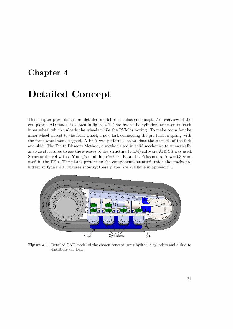
This chapter presents a more detailed model of the chosen concept. An overview of thecomplete CAD model is shown in figure 4.1. Two hydraulic cylinders are used on eachinner wheel which unloads the wheels while the RVM is boring. To make room for theinner wheel closest to the front wheel, a new fork connecting the pre-tension spring withthe front wheel was designed. A FEA was performed to validate the strength of the forkand skid. The Finite Element Method, a method used in solid mechanics to numericallyanalyze structures to see the stresses of the structure (FEM) software ANSYS was used.Structural steel with a Young’s modulus E=200 GPa and a Poisson’s ratio µ=0.3 wereused in the FEA. The plates protecting the components situated inside the tracks arehidden in figure 4.1. Figures showing these plates are available in appendix E.
Skid Cylinders Fork
Figure 4.1. Detailed CAD model of the chosen concept using hydraulic cylinders and a skid todistribute the load
21

Chapter 4. Detailed Concept
4.1 The Skid
The longitudinal forces are assumed to be distributed through the track’s chain andmotor since the track’s own brake is used while boring. Since the inner wheels are fullyunloaded, the pair of skids takes the force from Py and Pz. Figure 4.2 shows the greenhighlighted surfaces where these loads were applied on the top surfaces for the FEAmodel and the bottom surface Askid,b was set as fixed. The mesh was refined in the maxstress areas and the result converged with a maximum element size of 5 mm. The forcesPy and Pz used are specified in table 2.2. Figure 4.3 shows the final designs’ stresses.
Askid,b
Top surfaces
Figure 4.2. Boundary surfaces used in the FEM simulation of the skid
Figure 4.3. FEM simulation of the skid
22
4.2. The Fork
General calculations of the forces transferred from the skid to the chain were made toexamine the stresses in the chain. The area of the skid Askid,b is listed together with thetransferred pressure pskid,b in table 4.1.
Table 4.1. Skid dimensions and transferred pressure from the skid to the chain
Askid,b 0.117 m2
pskid,b 13.2 MPa
4.2 The Fork
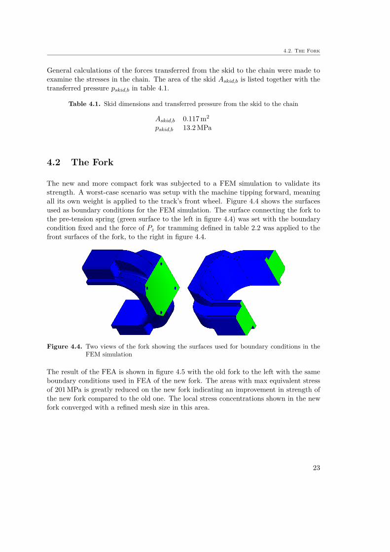
The new and more compact fork was subjected to a FEM simulation to validate itsstrength. A worst-case scenario was setup with the machine tipping forward, meaningall its own weight is applied to the track’s front wheel. Figure 4.4 shows the surfacesused as boundary conditions for the FEM simulation. The surface connecting the fork tothe pre-tension spring (green surface to the left in figure 4.4) was set with the boundarycondition fixed and the force of Pz for tramming defined in table 2.2 was applied to thefront surfaces of the fork, to the right in figure 4.4.
Figure 4.4. Two views of the fork showing the surfaces used for boundary conditions in theFEM simulation
The result of the FEA is shown in figure 4.5 with the old fork to the left with the sameboundary conditions used in FEA of the new fork. The areas with max equivalent stressof 201 MPa is greatly reduced on the new fork indicating an improvement in strength ofthe new fork compared to the old one. The local stress concentrations shown in the newfork converged with a refined mesh size in this area.
23

Chapter 4. Detailed Concept
Figure 4.5. FEA of the old (left) and new (right) fork
4.3 The Frame
The horizontal load Pz and the side load Py are assumed to be evenly distributed alongthe four small inner wheels and the longitudinal force (Px) is distributed to the hydraulicmotor as shown in figure 4.6
Pz
TM
Px
Py
Figure 4.6. The internal load distribution of the frame
The blue surface in figure 4.7 shows the surfaces making up the interface between thetracks and the machine. The interface was considered as out of scope and thereby nochanges or analyzes were done to this interface. When analyzing the frame, the surfaceswere regarded as frictionless supports, meaning the surfaces had zero displacement in itsnormal direction and were allowed to strain along its own plane.
The CAD model was imported as an assembly where all the parts that were in contactwith each other were set as "bounded" in ANSYS, meaning the software considered them
24

4.3. The Frame
as one solid when calculating the stresses.
Frictionless support
Figure 4.7. The surfaces making the interface between the machine and the tracks
Figure 4.9 shows the FEA done on the original frame that was provided by Atlas Copcoand one done on the frame that was designed for the new concept. Both models showedhigh stress concentrations in three sharp corners where welds are supposed to be. Crossframe 1 in figure 4.9 showed high stress concentrations both in the original frame and theconcept frame (upper circle in the detailed view) where it is joined with the rest of theframe. The mesh size shown in figure 4.8 was reduced in these parts but no convergenceof the stress was obtained due to the sharp corner. An attempt on making the bottomof Cross frame 1 stronger (where the stress concentration is situated) using the archgeometry cross frame 2 was made but wasn’t feasible due to the hole in the middle ofthe plate needed for the chain pre-tension spring (see figure 1.2).
The stress concentration areas are situated in welded joints which is highly problematic.To solve this problem, the industrial supervisor recommends consulting a weld expertbefore proceeding with manufacturing. The stress concentrations could be reduced withsmooth transitions in the corners.
Figure 4.8. Mesh used in the FEM model of the original (left) and concept (right) frame
25

Chapter 4. Detailed Concept
An extra cross frame part Cross frame 2b in figure 4.8 was added compared to the newframe to make the frame stronger. By adding this cross frame, the stresses in both crossframe 2a and cross frame 2b could be kept below 380 MPa. The parts were also madethicker to reinforce the frame.
MMPa
MPa
Cross frame 2a
Cross frame 2b
Frame provided by Atlas Copco
Concept 9 frame
Cross frame 1
Cross frame 2
Figure 4.9. Bottom view FEA of the original and concept frame using the boring loads intable 2.2
26

4.4. The Cylinders
4.4 The Cylinders
Several product catalogs of hydraulic component suppliers [13], [14], [15] were unsuccess-fully scanned to find cylinders compact enough to fit inside the tracks with the diameterspecified in table 3.5. The strongest cylinder compact enough to fit was FZ 250 -80 5001 201 32 [14] from Merkle AHP. The CAD model provided by the manufacturer websitewas imported to the CAD model (shown in figure 4.1). The small gap between the innerwheels and the chain shown in figure 4.10 allows the inner wheels to be fully unloadedwhile the machine is boring. The cylinders move the inner wheels, lifting the machinea distance δtot (minus the small gap) off the skid when changing operating mode fromboring to tramming. The exploded view in figure 4.11 shows the adapter plate whichwas designed to allow the cylinder to be mounted on the frame.
δ
SECTION A-A
Tramming
Boring
Gap
Contact
A
SECTION B-B
A
δ
B
B
Figure 4.10. Close up of how the cylinders lift the machine off from the skid when changingfrom boring to tramming
The data for the cylinder is presented in table 4.2 and shows that a system of eightcylinders achieve a total load capacity PzF Z greater than the tramming load Pz specifiedin table 2.2. The total allowable side load for the cylinders PyF Z is not sufficient compared
27

Chapter 4. Detailed Concept
1
2
3
4
5
No Name Quan�ty
1 M10x70 Socket Head Cap Screw 8
2 FZ 250 -80 50 01 201 32 1
3 M16x70 Socket Head Cap Screw 4
4 Cylinder Adapter Plate WW 1
5 Cylinder Bracket S009053_JT 1
Figure 4.11. Exploded view of how the cylinders are mounted to the frame
to the Py for tramming also shown in table 2.2. The system operating pressure psystem
was set to the max pressure pop,max to achieve these loads.
Table 4.2. Data for Cylinder FZ 250 -80 50 01 201 32
pop,max 250 barpsystem 250 bardpiston 80 mmPzF Z 1.01 MNPyF Z 0.03 MN
4.5 PDS evaluation
The final design was evaluated in regard to the PDS in appendix A and the result ispresented in table 4.3.
28

4.5. PDS evaluation
Table 4.3. Evaluation of the final concept compared to the PDS
Static vertical load Pz YesStatic side load Py Boring Yes, Tramming NoCycle time Not confirmedAmbient temperature working Yes, according to hydraulic component
data sheetAmbient temperature storage Yes, according to hydraulic component
data sheetVibrations Yes, the loads compensate for dynamic
effectsDirty and wet environment Yes, the components are insensitive to dirt
and moistureLife in service Yes, the components are maintenance
friendly and dimensioned to lastShipping and size Yes, the design respects the dimension
specificationAesthetics and appearance No, the level of detail does not include
aestheticsMaterial Yes, structural steel was used for the de-
signStandards Yes, standardized components were used
except for the newly designed fork and skidErgonomics Yes, standard tools are used for mainte-
nance and no springs were usedQuality and reliability Not evaluatedShelf life Yes, the components used will last the 6
month shelf lifeTimescale Yes, the deadline for May 2017 was metSafety Yes, the unloading operation is au-
tonomousPatents Yes, no patent clashes were foundDocumentation Yes, the thesis together with the CAD-
model documents the design extensivelySustainability Partially, hydraulic fluid is normally fos-
sil fluids. Main components are made outof structural steel with no conflict minerals
29


Chapter 5
Discussion and Conclusion
This chapter includes a discussion regarding the design of the concept with its strengthsand weaknesses. The result of the main new components described in chapter 4 isdiscussed and compared to the PDS in appendix A. The methods used in the project arediscussed and the conclusion sums up the result of this thesis.
5.1 Discussion
Even in a quite low level of detail of the CAD model (piping, wiring, welds joints werenot included) there were quite a lot of difficulties to find room for the cylinders in theframe. Parts in the frame were moved which led to other parts needing adjustments. Themodel was built as a bottom-up assembly [16]. In hindsight, a lot of advantages couldhave been found with a top-down assembly [16] when changing a dimension of one partmeant dimensional changes on several other parts.
Even though the patent search performed in chapter 3.4 didn’t show any patent clashes,there’s still a need for a more detailed search of existing patents. Experts in patents andpatent search should be consulted before manufacturing the concept.
5.1.1 Skid Discussion
The FEA done in chapter 4.1 indicates that the skid is strong enough for the high loadsthe skid needs to sustain when the machine is boring. The stresses are in the sameorder as the yield strength of conventional construction steel. This suggests that a morein-depth study of how the dynamic forces affect the life length of the structure regardingfatigue. The loads in chapter 2.1 given by Atlas Copco are supposed to compensate fordynamic effects but a more in-depth study might still be needed.The track’s chain was assumed to be strong enough for the loads in table 2.2. The
31

Chapter 5. Discussion and Conclusion
pressure in table 4.1 indicates a tolerable level but this needs to be confirmed by thetrack manufacturer.
5.1.2 Fork Discussion
The new fork creates more space for the cylinders to be fitted in the frame and the FEAdone with the tipping over scenario indicates that the fork is strong enough for the task.Manufacturing cost and complexity of the new fork is increased but compared to addingmore tracks it is still found to be a profitable choice.
5.1.3 Frame Discussion
The stress concentration where Cross frame 1 in figure 4.9 is joined with the rest ofthe frame needs to be resolved. As earlier suggested, an expert in welding should beconsulted to decide acceptable stress levels and how to reduce them. Furthermore, thestress level of 380 MPa limits the choice of material to a higher quality steel compared toconventional construction steel with a yield strength of 235 MPa. Just as with the skid,a more in-depth study of fatigue may be needed.
5.1.4 Cylinders Discussion
The cylinders were compact enough to fit inside the track with some modifications of theframe. The level of detail in the given CAD model did not include electric components,wires or pipes. The placements of such parts are now needed to be adjusted to the newdesign of the frame.
The cylinders used in chapter 4.4 are too weak for the side load Py when tramming.Either should linear guides be added connecting the inner wheels to the frame to takethese side loads or the cylinders should be changed to larger ones.
5.1.5 Method Discussion
The following reflections of the methods used in the thesis could be done
• The tedious work of creating the PDS (appendix A) was of great support whenquestions about prioritizes arose while designing the concepts
• Both the Stage Gate flow chart and the Gantt chart proved to be of great help tomeet deadlines
• The Gantt chart had to be revised several times and details were added to keepit true to the project. Working with an outdated Gantt chart would defeat thepurpose of using it for structure your work and keeping deadlines
32

5.2. Conclusion
• The Morphological Matrix was the root for coming up with the final concept. Theearly idea of having a skid mounted on the hydraulic cylinders to lift the machinewhen it was boring proved to be less effective than the later generated and finallychosen concept of the moving inner wheels.
• The Pugh’s Evaluation Matrix proved to be a good way of systematically evaluatethe concepts.
• The controlled convergence method was the ground for coming up with the finalconcept. The method could be even more effective when working in groups allowingfor more creative thinking.
5.2 Conclusion
In conclusion, the concepts fulfill the PDS in appendix A with some deviations:
• The cylinders used aren’t strong enough for the side loads when the machine istramming.
• The frame is showing stress concentrations in welded corners. The stresses need tobe reduced or moved out of the joint.
• The desired hydraulic operating pressure psystem was exceeded with the chosencylinders.
• The concept’s level of detail did not include specifying a hydraulic pump or piping.
• Environmental effects:
– How moist and dirt affect the hydraulic cylinders hasn’t be investigated.
– How dirt between the skid and the chain affect its performance hasn’t investi-gated.
– Ambient temperature hasn’t been studied. The hydraulic oil must be compat-ible with these temperatures.
• The hydraulic cylinder’s life in service isn’t specified. However, service and replace-ment of the cylinders is easy with the service slots in the frame.
• The quality and reliability haven’t been investigated. The specified availabilityspecified in the PDS still needs to be verified.
• Regarding sustainability, no conflict minerals have been found in the design. How-ever, the use of hydraulics implies the use of fossil oil.
33


Chapter 6
Future Work
The concept could be developed further to make it a better and more detailed solution.The following parts are recommended to develop further:
• Add linear guides to reduce the side load of the hydraulic cylinders
• Reducing the clearance δtot and creating more space for a larger diameter for thespring could allow the use of Belleville springs using the theory in chapter 2.3.Using springs instead of hydraulic components could create a less complex design
• Create a more detailed design of the concept including source and distribution forhydraulic power (pump and piping)
• Solving the stress concentration in cross frame 1. Mimicking the bottom geometryof cross frame 2 is possibly a solution
35

References
[1] S. Pugh, Total design - integrated methods for successful product engineering.Wokingham: Addison-Wesley, 1990, pp. 44–66.
[2] R. G. Cooper, “Stage-gate systems: A new tool for managing new products”,Business Horizons, pp. 44–45, 1990.
[3] S. El Wakil, Processes and design for manufacturing. Boston, PWS PublishingCompany, 1998, pp. 14–15.
[4] ——, Processes and design for manufacturing. Boston, PWS Publishing Company,1998, pp. 430–459.
[5] P. R. Childs, Mechanical design engineering handbook. Burlington: Elsevier Science,2013, pp. 664–671.
[6] G. Pahl, W. Beitz, J. Feldhusen, and K. Wallace, Engineering design : A systematicapproach. Springer London, 2007, pp. 169–186.
[7] S. Pugh, Total design - integrated methods for successful product engineering.Wokingham: Addison-Wesley, 1990, pp. 67–89.
[8] Lesjöfors AB, Spring catalogue 13, http://www.lesjoforsab.com/teknisk-information/standard_stock_springs_catalogue_13_- _english_id1107.pdf accessed 2017-04-20, 2017.
[9] Danly IEM, Jis springs, http://www.daytonlamina.com/sites/default/files/doc/DanlyIEM-JIS-Springs.pdf accessed 2017-04-20, 2017.
[10] K. Björk, Formler och tabeller för mekanisk konstruktion. Karl Björks Förlag HB,1999, p. 53.
[11] E. Parr, Hydraulics and pneumatics: A technician’s and engineer’s guide. UnitedKingdom, Butterworth Heinemann, 2013, p. 125.
[12] ROEMHELD, Block cylinders double acting, max. operating pressure 500 bar,[http://www.roemheld.com/en/roemheld.aspx?cmd=PDF&Article=1549100&csid=4912&sm=Kolbendurchm=100 accessed 2017-04-20], 2017.
[13] ——, Roemheld product catalogue, [http://www.roemheld.com/en/roemheld.aspx?cmd=PDFS accessed 2017-04-20], 2017.
[14] AHP Merkle, Product catalogue, [https://ahp.partcommunity.com/3d-cad-models/ahp-merkle/?info=ahp accessed 2017-04-20], 2017.
37

References
[15] Parker Hannifin Corporation, Cylinder product catalogue, [https://www.parker.com/literature/Industrial%20Cylinder/cylinder/cat/english/HY08-1114-6_NA_2H-3H%20.pdf accessed 2017-04-20], 2017.
[16] D. D. Gajski, S. Abdi, and A. Gerstlaue, Embedded system design modeling, synthesisand verification. London New York: Springer Dordrech Heidelberg, 2009, pp. 35–38.
[17] B. Bali, U. Naeher, D. Ruppen, and P. Schütte, “Conflict minerals 3tg: Miningproduction, applications and recycling”, Current Opinion in Green and SustainableChemistry, no. 1, pp. 8–12, 2016.
38

Appendix A
The Elements of the ProductDesign Specification
This chapter extends the summary of the PDS in chapter 1.6 treating the complete listof elements [1]. The elements were used to create the Pugh’s Matrix in chapter 3.1
• PerformanceThe static load capacity and cycle time is presented in table A.1
Table A.1. Static load when operating
Static vertical load Pz 2.5 MNStatic side load Py 0.5 MNCycle time (tramming - ready to bore - tramming) 10 seconds
• EnvironmentAmbient temperature working: 0 ◦C to 35 ◦CAmbient temperature storage: −5 ◦C to 70 ◦CVibrations: The static load supplied by Atlas Copco Pz and Px are dimensionedfor dynamic loadsDirty and wet environment.
• Life in ServiceThe machine should operate 24 hours a day, 5 days a week.Total life in service: 1500 h
• Target Product CostThe alternative to an unloading system is adding more tracks. Therefore, the costof the unloading system should not exceed that of adding more tracks.
39

Appendix A. The Elements of the Product Design Specification
• CompetitionNo competition is considered since Atlas Copco reports that no other solutions areavailable on the market.
• ShippingThe RVM needs to be transported down the mine shaft in an elevator. As longas the unload sharing unit fulfills the requirement of fitting within the tracks, thisshould not be a problem.
• PackingPacking is considered as out of scope.
• QuantityWhen the concept is realized, the quantity will be very low. Approximately 1-3machines.
• SizeThe design should fit inside the tracks of the RVM.
• WeightRegarding the he large weight of the machine (160 tonnes) and the size constraints,the weight of the design is subordinate.
• Aesthetics and AppearanceFlat surfaces should be colored with the Atlas Copco yellow color.The design should appear robust and give the impression of handling the roughmine environment.
• MaterialsSteel alloys are used for structural frames. These are in general preferred overaluminum and other metals on these machines according to Atlas CopcoHydraulic components may be used.
• Product life spanThis section is subordinate since only one machine is planned to be manufactured.
• Standards and SpecificationsEuropean standard components should be used when possible but customized partsmay be designed to find a solution.
• ErgonomicsWhen using springs (pre-tensioned), the design should allow for a safe assembly.Maintenance should be possible using standard tools.
• CustomerThe customer of the design is Atlas Copco who wants to integrate the solution intheir machine (the RVM).
• Quality and Reliability
40

The RVM availability is set at 80%. The availability is calculated using Mean Timeto Failure, the mean time a system takes to fail (MTTF) and Mean Time to Repair,the mean time it takes to repair the system (MTTR):
Availability = MTTF
MTTF +MTTR(A.1)
• Shelf lifeThe design should survive 6 months’ shelf life.
• ProcessesAtlas Copco has a high level of in-house process competence, including welding,milling, turning, grinding, casting, hydraulic tubing and electric wiring making thisspecification subordinate.
• Time-ScalesThe concept design should be completed no later than May 2017.
• TestingHow the product should be tested is considered as outside of the conceptual designscope.
• SafetyNo human contact when the unloading system operational.It should be safe to move around the machine while the machine is tramming.
• Company ConstraintsNo company constraints are considered in this project since this is considered as asmall and low quantity part of the machine.
• Market ConstraintsSince the customer is considered to be Atlas Copco and the RVM project is underway,no more market constraints will be taken in to consideration.
• Patents, Literature and Product DataPossible patent clashes should be investigated.
• LegalLegal parts regarding miss-use and defects are outside of the scope of the conceptualdesign stage.
• InstallationThe unloading system should be applicable to the RVM tracks but alteration ofthe track’s frame is allowed to achieve the target load.
• DocumentationThe design is documented extensively in the master thesis.
41

Appendix A. The Elements of the Product Design Specification
• DisposalThe disposal of the unloading system is regarded as outside of the scope of theconceptual design stage.
• SustainabilityEven though [1] does not handle the matter of sustainability, with today’s challengesof global warming the author considers this to be something that must be regarded.Fossil fluid and material should be kept to a minimum and conflict minerals [17]should be avoided as far as possible.
42

Appendix B
The Gantt chart
The Gantt chart shown in B.1 was used as a base for scheduling when each part of theproject was supposed to be done. The progress bars were filled with blue as progresswas made. This was done at least every Friday when the chart was uploaded to theworkspace shared with the academic supervisor.
43

Appendix B. The Gantt chart
44

Figure B.1. Gantt chart for the project45


Appendix C
The Criteria of Pugh’s EvaluationMatrix
The following criteria were used in chapter 3.1 to evaluate the previously generatedconcepts. The PDS described in chapter 1.6 was used as a base for creating the crite-ria.
• Static load performanceCan the concept effectively take the horizontal load?Can the concept effectively take the side load?Is the mechanism suitable for taking high static load?Since the frame in its current state needs to be reinforced the load distributer needsto be compatible with frame reinforcements.
• Track chain pressureAn even load distribution acting on the track’s chain is required to reduce the stressof the chain.
• Cycle timeThe cycle time set to 10 seconds needs to be met
• Environmental effectsBoth the storage and operating temperature spans need to be met.The RVM uses water to cool the cutter head and reduce the dust created whencutting. This creates a dirty and wet environment.The load distributor needs to endure the dusty and dirty environment in the mine.
• SustainabilityDoes the concept have any environmentally harmful material or conflict minerals[17]?
• Maintenance
47

Appendix C. The Criteria of Pugh’s Evaluation Matrix
Does the maintenance take the RVM out of service for longer periods of time? Isthe availability met? (80%)
• CostIs the estimated development and production cost higher than the datum concept?Does the concept require a lot of expensive custom made parts?
• ComplexityDoes the concept use energy mediums (hydraulic, electric, mechanic) than thedatum? How complex is the concept regarding number of parts used in assembling?Does the concept involve complex control units? Is manufacturing of the conceptfeasible with respect to the manufacturing cost?
• SizeHow large are the dimensions of the concept? One main requirement is that theconcept should fit inside the tracks.
48

Appendix D
The MATLAB script used forcalculation of the Bellevillespring
MATLAB script used for calculating Belleville springs, hydraulic pressure and cylinderdiameter. The chosen cylinders’ load capacity and side load capacity are also calcu-lated.
%MATLAB script for Master Thesis Machine Design% RVM tracks Jonas Torstensson 2017-02-10% Calculating RVM forces on the trackclear all;close all;clcm_equv=200e3 ; % Equivalent mass of RVM while tramming [kg]T_max=222764; % Max torque of the hydraulic motor in the tracks [Nm]mu_t=0.7 ; % Friction coefficient between the tracks and the groundg=9.818 ; % Gravity constant [m/s^2]P_yboring=0.5e6; %Forces in y-direction while boringr_sprocket=615.5e-3; % Radius of track sprocket [m]alfa_g=5; % Ground tilt angle [deg]P_ztram=m_equv*g/2; % Load on each track in z-directionP_xtram=T_max/r_sprocket;disp(['P_xtram= ',num2str(P_xtram*10^-6),' [MN]'])P_ytram=P_ztram*sind(alfa_g);disp(['P_ytram= ',num2str(P_ytram*10^-6),' [MN]'])disp(['P_ztram= ',num2str(P_ztram*10^-6),' [MN]'])P_zboring=2.5e6 ; %Vertical load on track when boring [Nm]P_xboring=mu_t*P_zboring;disp(['P_xboring= ',num2str(P_xboring*10^-6),' [MN]'])
%% Approximating the hydraulic cylinders sizedisp(' ');disp('Hydraulics');n_wheels=4; % Number of wheels per track
49

Appendix D. The MATLAB script used for calculation of the Belleville spring
n_cylperwheel=2;p_popmax=300e5; % max hydraulic pressure specified by the manufacturer of ...
the specific cylinder range (Roemheld)P_zwheel=P_ztram/n_wheels; % Load on each wheel (4 per track)P_zwheel_side=P_zwheel/n_cylperwheel; % Pressure on each side of the wheelsp_max=250e5 ;% Max system pressureA=P_zwheel_side/p_max;r_piston= sqrt(A/pi); % Cylinder radius for max system pressure in regard ...
to P_zP_y_cyl=P_ytram/(n_wheels*n_cylperwheel);r_piston_sl=sqrt(P_y_cyl/(0.03*8*pi*p_popmax)); % Min piston radius ...
considering the side load and condition of max 3% of max pressure load
disp(['Load on each cylinder while tramming P__y_cyl= ...',num2str(P_y_cyl*10^-3),' kN', ' P_z_cyl= ...',num2str(P_zwheel_side*1e-3),' kN'])
disp(['Min piston diameter d= ', num2str(r_piston*2e3), ' mm for tramming'])disp(['Side load min piston diameter d= ', num2str(r_piston_sl*2e3), ' mm ...
for tramming'])disp(['Using system pressure ',num2str(p_max*1e-5),' bar and ...
',num2str(n_wheels), ' wheels per track and ...',num2str(n_cylperwheel),' cylinder per wheel'])
%% Ground pressuredispdisp(' ');disp('Check ground pressure');A_ideal=541255.05e-6; %Area of track below the small wheels%A_skid=(127884.28+127883.41)*1e-6; % Area where the skid would act on ...
the track.A_skid=2*116886.41e-6;%P_tot_bor=sqrt(P_xboring^2 + P_yboring^2 + P_zboring^2);p_ideal_bore=P_tot_bor/A_ideal;disp(['Ideal ground pressure when boring p_ideal= ...
',num2str(p_ideal_bore*1e-6), ' MPa']);p_track_boring=P_tot_bor/A_skid;disp(['Track pressure when boring p_track_boring= ...
',num2str(p_track_boring*1e-6), ' MPa']);%% Compression springF_sm=P_ztram/24;disp(' ');disp('Compression springs')disp(['Compression spring force F_sm = ',num2str(F_sm*1e-3),' kN'])%% Belleville springdisp(' ');disp('Belleville Spring dimensioning');D_o=65e-3 ; % outer diameter of spring [m]E=207e9; % Youngs modulus for spring steel [Pa]mu=0.3 ; % Poissons ratio for spring steelD_i=D_o/2;%F_flat=2*62.5/(3*0.75) *1e3; % Force for the spring to flatten outF_flat=P_ztram/(.75*16);Sigma_uts=1810e6; % Ultimate strength of SS-EN 1.4021delta_tot=30e-3; %Required displacement for the wheels (spring stack)eta_min=0.2; % Pre tension quote from h_0%htquote=0.01:0.1:1.414 ; % the quota h/t set to give a (near) constant ...
force for the defelction
50

kappa=[0.03:0.005: 0.4];t=1/1072 * ( (D_o^2 * F_flat)./(kappa)).^0.25; % Assuming constant spring ...
force and a D_o/D_i=2%disp(['thicknsess t= ',num2str(t*1e3),' mm'])h=t.*kappa;%disp(['height h= ',num2str(h*1e3),' mm'])delta_min=.65*h;delta_max=1.35*h;Delta_delta=delta_max-delta_min;%disp(['Delta_delta= ',num2str(Delta_delta*1e3),' mm'])tot_h=h+t;N=4; % Number of springsStack_height=N*tot_h; % Stack height using N springs%disp(['Stack_height= ',num2str(Stack_height*1e3),' mm'])%disp(['Total deflection delta= ',num2str(N*Delta_delta*1e3),' mm'])L_0faktor=.8*2*(1+1/1.414);L_0t=.8*(1+1/1.414)*h;% Calculating the stresses in the spring%t=[1:0.1:2]*t;R_d=D_o/D_i;K_1=6/(pi*log(R_d)) *( (R_d-1)^2 /R_d^2);K_2=6/(pi*log(R_d))*( (R_d-1)/log(R_d) -1);K_3=6/(pi*log(R_d))*( (R_d-1)/2);K_4=((R_d*log(R_d)-(R_d-1))/log(R_d))* R_d/ ((R_d-1)^2);K_5=R_d/(2*(R_d-1));delta_max=0.75*h;sigma_c= 4*E.*delta_max/(K_1*D_o^2*(1-mu^2)) .*( ...
K_2.*(h-delta_max./2)+K_3.*t);sigma_ti=4*E.*delta_max/(K_1*D_o^2*(1-mu^2)) ...
.*(-K_2.*(h-delta_max./2)+K_3.*t);sigma_to=4*E.*delta_max/(K_1*D_o^2*(1-mu^2)) ...
.*(K_4.*(h-delta_max./2)+K_5.*t);%disp(['Stress sigma_c= ',num2str(sigma_c*1e-6),' MPa'])hold onplotc=plot(kappa,sigma_c*1e-6,'LineWidth',1.7);plotti=plot(kappa,sigma_ti*1e-6,'LineWidth',1.1);plotto=plot(kappa,sigma_to*1e-6);plotuts=plot([kappa(1) kappa(end)], [Sigma_uts*1e-6 Sigma_uts*1e-6],'--');legend('\sigma_c','\sigma_t_i','\sigma_t_o','\sigma_u_t_s');xlabel('Quota \kappa = h_B_W/t_B_W'); ylabel('Stress \sigma [MPa]');grid onno=find(kappa==0.105);delta_no=h(no)*0.75; %Maximum deflection of one springreq_N=delta_tot/(delta_no); % Requirered number of springs for the ...
deflection delta_tot with the chosen kappa(no)%stack_Height=ceil(req_N)*tot_h(no)*(1-.2);stack_Height=ceil(req_N)*h(no)*(1-eta_min+1/kappa(no));disp(['Minimum kappa ', num2str(kappa(no))])disp(['Thickness t= ', num2str(t(no)*1e3),' mm'])disp(['Cup height h= ', num2str(h(no)*1e3),' mm'])disp(['Spring height L_0= ', num2str(tot_h(no)*1e3),' mm'])disp(['Max deflection of one spring delta= ', num2str(delta_no*1e3),' mm'])disp(['Required number of springs= ', num2str(ceil(req_N)),' pcs']) % ...
req_N rounded up!
51

Appendix D. The MATLAB script used for calculation of the Belleville spring
disp(['Stack height L_stack= ', num2str(stack_Height*1e3),' mm'])
%% Cylinder FZ 250 -80 50 01 201 32d_FZpist=80e-3 ; % Piston diameter for the chosen cylinder [m]p_FZop=250e5; % (max) operating pressure of the cylinder [Pa]n_FZ=8 ; % Total number of pistons mounted on the trackA_FZp=d_FZpist^2 *pi/4; % Piston area of the piston [m^2]F_zFZtot=p_FZop*A_FZp * n_FZ; % Total load capacity of the cylindersdisp(['Total load capacity of the FZ Cylinders P_tot= ...
',num2str(F_zFZtot*1e-6), ' MN'])F_yFZtot=F_zFZtot*0.03; % Total allowable side load for the FZ cylinderdisp(['Total load capacity of the FZ Cylinders P_tot= ...
',num2str(F_yFZtot*1e-6), ' MN'])
52

Appendix E
Pictures of the final design
This chapter shows pictures of how the track’s plates protecting the components insideare mounted.
Figure E.1. Front view of the final design of the track
53

Appendix E. Pictures of the final design
Figure E.2. Tilted front view of the final design of the track
Figure E.3. Back view (interface to machine) of the final design of the track
54


TRITA MMK 2017:45 MKN 197
www.kth.se