conceptual design for the acceleration of polarized … notes....- b 4 0 accelerator division ags...
TRANSCRIPT
.- b
4
0
A c c e l e r a t o r D i v i s i o n AGS D e p a r t m e n t
BROOKHAmN NATIONAL LABORATORY A s s o c i a t e d U n i v e r s i t i e s , Lnc.
U p t o n , NY 11973
A G S / A D / T e c h . N o t e N o . 407
Conceptual Design for the Acceleration of Polarized Protons in RHIC
K.Brown (BNL) G.Bunce (BNL) E.Courant (BNL) R.Fernow (BNL) S.Y .Lee (Indiana) A.Luccio (BNL) Y.Makdisi (BNL) S.R/Iane (BNL) L.Ratner (BNL)
T.Roser (Coordinator, BNL) H.Spinka (ANL) S .Tepikian (BNL) A.G.Ufimtsev (IHEP)
D.Underwood (ANL)
May 24, 1993
lWork was performed under the auspices of the U.S. Department of Energy and was supported by grants from the U.S. National Science Foundation

CONTENTS
1 Introduction 3
2 Polarized Ion Source, AGS and Transfer of the Polarized Beam to RHIC
3 Siberian Snakes and Spin Rotators in RHIC 3.1 General Lay-out . . . . . . . . . . . . . . . . . . . . . . e . . . . . 3.2 Siberian Snake and Spin Rotator Design . . . . . . . . . . . . . . 3.3 Effect on Lattice . . . . . . . . . . . . . . . . . . . . . . . . . . . 3.4 Compensation for Detector Solenoids . . . . . . . . . . . . . . . .
4 Acceleration of Polarized Protons in RHIC 4.1 Depolarizing Resonance Strengths . . . . . . . . . . . . . . . . . 4.2 Effect of Siberian Snakes . . . . . . . . . . . . . . . . . . . . . . . 4.3 Sextupole Depolarizing Resonances . . . . . . . . . . . . . . . . . 4.4 Spin Tune Spread and Modulation . . . . . . . . . . . . . . . . . 4.5 Betatron Tune Spreads and Modulations . . . . . . . . . . . . . .
5 Storage of Polarized Protons in RHIC
6 Measuring the Beam Polarization in RHIC
7 Luminosity of Polarized Proton Collisions
8 Spin Reversal of the Stored Beams
9 Operational Modes of RHIC for Polarized Proton Running
10 Conclusions
4
6 6 7 8 9
10 10 11 12 13 14
15
17
19
20
21
22
1
11 Figure Captions 23

1. INTRODUCTION
The Relativistic Heavy Ion Collider (RHIC) at Brookhaven allows for the unique possibility of colliding 250GeV polarized proton beams at luminosities of up to 2 x ~ r n - ~ s - ' . This report describes the technical considerations of accelerating polarized proton beams in RHIC to a top energy of 250 GeV and of performing col- lisions of longitudinally and transversely polarized protons in the two interaction regions occupied by the PHENIX and STAR detectors.
Fig. 1 shows all the major components that are required for the acceleration of polarized beams to RHIC top energy. The feasibility of accelerating polarized protons in RHIC was the basis of the proposal the RHIC Spin Collaboration (RSC) submitted to the Brookhaven PAC in October 1992[1].
3

. -.
2. POLARIZED ION
RHIC TRANSFER OF THE
SOURCE, AGS AND POLARIZED BEAM TO
To achieve high luminosity, high energy polarized proton collisions in RHIC the intensity of the present AGS polarized proton source[2] is sufficient. The source produces about 35 p A of H- with 75 - SO% polarization in 350 ,us pulses at a repetition rate of 5 Hz. The polarized H- ions are accelerated to 200 MeV with an RFQ and the 200 M H z LINAC with an efficiency of about 50%. Twenty pulses of H- ions are strip-injected, accumulated, and captured into a single bunch in the AGS Booster with an estimated efficiency of about 50%. The bunch in the Booster will then contain NB = 4 x 10l1 polarized protons with a normalized emittance of about EN = 1 0 ~ mm mrad. The single bunch of polarized protons is accelerated in the Booster to 1.5 GeV kinetic energy and then transferred to the AGS, where it is accelerated to 25 GeV .
During acceleration, the polarization may be lost when the spin precession frequency passes through a depolarizing resonance. These resonances occur when the number of spin precession rotations per revolution GY (G = 1.793 is the anomalous magnetic moment of the proton, y = E) is equal to an integer (im- perfection resonances) or equal to kP f uy (intrinsic resonances). Here P = 12 is the superperiodicity of the AGS, uy = 8.S is the vertical betatron tune and k is an integer. The depolarization is caused by the small horizontal magnetic fields present in all ring accelerators which, at the resonance condition, act coherentlj- to move the spin away from the stable vertical direction. Imperfection resonances are due to the horizontal fields caused by the vertical closed orbit errors and in- trinsic resonances are caused by the horizontal focusing fields which are sampled due to the vertical betatron motion. The two resonances in the Booster (Gy = 3 and Gy = 4) are too weak to cause any significant depolariza.tion. Traditionally. the depolarizing resonances in the AGS were corrected by the tedious harmonic correction method for the imperfection resonances and the tune jump met.hod for
e the intrinsic resonances[3].
In the approved experiment E-880 at the AGS to be started in 1993, the fea- sibility of polarized proton acceleration by using a 5% partial Siberian Snake[4] will be tested. Previous experience with polarized proton acceleration in the AGS indicates that a 5% Snake is sufficient to avoid depolarization due to the imperfec- tion resonances without using the harmonic correction method. The remaining six important intrinsic resonances can be corrected by the proven tune jump method. At 25 GeV, the polarized protons are transferred to RHIC. At this energy t,he transfer line between the AGS and RHIC is spin transparent[5].
We estimate that the overall efficiency of the acceleration and beam transfer is better than SO%, giving 2 x 10l1 protons per bunch. With proper care in the tune jump procedure the normalized emittance of the bunch is expected to be less than 20nmmmrad. We repeat the process until all .57 bunches of each ring are filled. Since each bunch is accelerated independently? we have the option of preparing the polarization direction of each bunch independently. Filling both RHIC rings with 57 bunches each and acceleration to full energy will only take about 10 minutes which is short compared to the expected lifetime of the stored polarized proton beams in RHIC of many hours.

3. I N
S I B E R I A N SNAKES A N D S P I N ROTATORS RHIC
3.1. General Lay-out
By inserting two full Siberian Snakes on opposite sides of each of the two RHIC rings, depolarization from imperfection and intrinsic depolarizing resonances can be avoided up to the top energy of 250 GeV. In addition to the Siberian Snakes, spin rotators are required at the intersection points used by PHENIX and STAR to allow for measurements of spin effects with longitudinally polarized protons. The spin rotators rotate the polarization from the vertical direction into the horizontal plane on one side of the interaction region and restore it to the vertical direction on the other side.
The Siberian Snakes introduce a 180" spin rotation without generating a net orbit distortion. The spin rotators placed around the experiments rotate the spin by 90" to provide longitudinal polarization at the interaction region again without generating net orbit distortions. In both cases the spin rotation is accomplished with a sequence of large bore, constant field, superconducting dipole magnets. The large bore is necessary to accommodate the orbit excursions inside the Snake and the spin rotators.
Each Snake rotates the spin by 150" around a horizontal axis and the two axes of the two Snakes of each ring have to be perpendicular on each other. We are planning to use pairs of Siberian Snakes with one Snake rotating the spin around an axis that points 45" to the outside and the other Snake rotating around an axis that points 45" to the inside of the ring. In this case all Snakes can be constructed in same way. Also, the two Snakes of each ring have to be installed on opposite sides of the ring. In fact, the beam direction in one Snake has to he exactly opposite to the beam direction in the other Snake to wit.hin 0.:3m7-nd.
The following is a summary of the proposal for the locations and construction of the Siberian Snakes and the spin rotators (see Fig. 1):
'
6

0 Two pairs of full Siberian Snakes, one pair in each ring, are installed at the 4 o’clock and 10 o’clock regions as shown in Fig. 2. These Snakes rotate the spin around axes that point 45” to the inside or outside of the ring. We are planning to install the Siberian Snakes in the 1 3 m long, cold straight sections between Q7 and Q8.
e
0 The two pairs of spin rotators, for PHENIX at the 8 O ’ C ~ O C ~ region and STAR at the 6 o’clock region, are installed in the 4 0 m long straight sec- tions between Q3 and Q4 on either side of the interaction region. The beam direction in the straight sections is different from the direction in the colli- sion area by 3 .67mrad which introduces a spin rotation that is larger by a factor of Gy. This means that the spin rotators have to prepare a horizontal polarization direction such that after this spin rotation the desired longi- tudinal polarization direction is obtained at the interaction point. Fig. 3 shows the size of the maximum orbit excursion inside the spin rotators as a function of beam energy. To limit the orbit excursions in the spin rotators to the same value as in the Snakes, which is about 7 0 m m we are planning to inject with the spin rotators turned off and only turn them on at an energy of 7 5 Gel/ or higher if needed by the experiments. The turn-on can be done adiabatically without loss of polarization. 8
3.2. Siberian Snake and Spin Rotator Design
For both the Siberian Snake and the spin rotators we used the 200mm. bore, superconducting RHIC DX dipole magnets as a basis for the design. The Snake consists of seven magnets with dimensions listed in Table 1. The parameters are a result of an optimization using a three dimensional orbit and spin tracking program that includes the effects of fringe fields. The maximum beam excursion at the injection energy is 7 0 m m . The result of the orbit and spin tracking is shown in Fig. 4. The horizontal and vertical dipole magnets are powered by separate power supplies. This allows for an adjustment of the spin tune to 1/2 and also for small changes of the direction of the rotation axis to compensate for the effect of the detector solenoids as will be discussed below. This is shown in Fig. 5
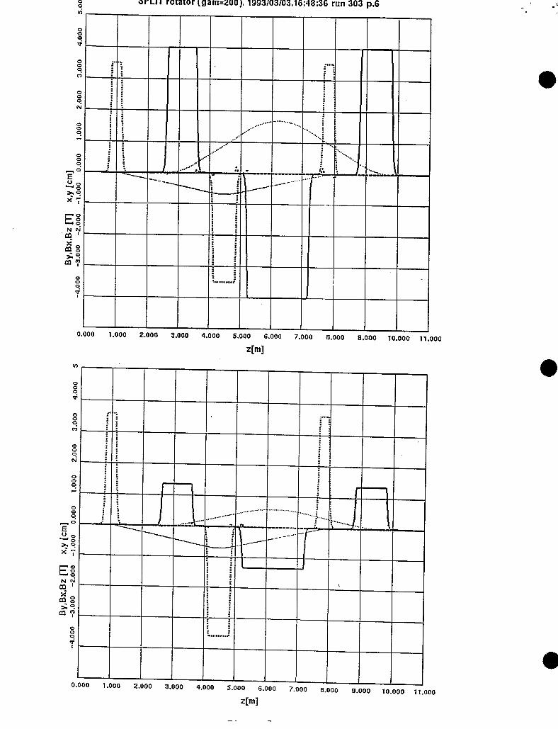
The spin rotators are constructed of 3 vertical and 3 horizontal dipole magnets. With independent power supplies for the vertical and horizontal dipoles. respec- tively, it is possible to rotate the polarization into any direction of the horizontal plane according to the requirements outlined in the previous section. To ensure

Deflection direction H V -H -V H Dipole Magnetic Field [Tesla] 3.742 4.060 3.742 4.060 3.742 Magnet Start [m] 0.000 0.599 1.600 2.619 4.340 Magnet End Em] 0.215 1.219 2.238 3.959 4.978
Table 3.1: Parameters of the Siberian Snake magnets
V -H 4.060 3.742 5.359 6.962 5.979 7.180
Table 3.2: Parameters of the Spin Rotator magnets
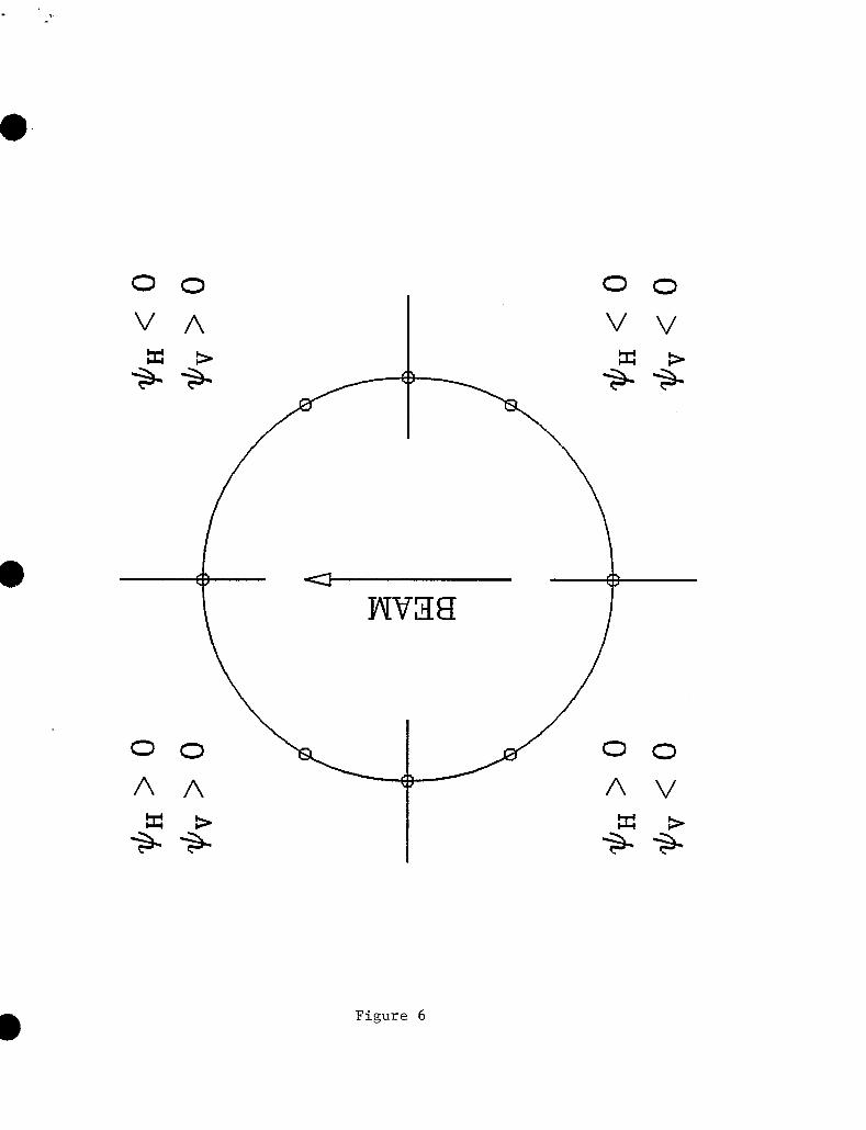
that the spin lies in the horizontal plane the spin rotation angles $H and $V in the horizontal and vertical dipoles, respectively, have to obey the equation[S]
1 sin $H sin $v = f7.
2 The relative sign of $H and $V for different directions in the horizontal plane
are shown in Fig. 6. Fig. 7 shows the result of the tracking calculations for the spin rotator that produces longitudinal polarization (top) and radial polarization (bot tom).
3.3. Effect on Lattice
Calculations of the changes to the RHIC lattice parameters were performed using MAD. It is worth noting that the survey algorithm in MAD does not work properly since the Snakes introduce torsion into coordinate system. The following changes in the lattice parameters are caused by the introduction of two Snakes, each located between Q7 and Q8 as described above:

Comment V X *Y D Y D F I 4 P; 2.0m 2.0m
With Snakes, Injection energy 28.837 28.836 1.738m 0.110m 2.0m 2. lm With Snakes, Top energy 28.827 28.823 1.678 m 0.009 m 11.0 m 2.0 m
No Snakes 28.827 28.823 1.674 m 0
Clearly the changes of the lattice parameters are very small and can easily be corrected for.
3.4. Compensation for Detector Solenoids
The STAR and PHENIX detectors use solenoid magnets as spectrometers. With transverse polarization at the collision point the solenoid contributes to the im- perfection resonance strength,
1 + G J Bllde 2n Bp G r n p s o l = --
For a 5 Tesla-meters integrated solenoid field strength, the resulting spin resonance strength is about 0.02 at the injection energy and 0.003 at 250 GeV/c.
With longitudinal polarization at the collision point the longitudinal field ro- tates the polarization around its axis and thus changes the spin tune. The spin tune is changed by 0.03 to 0.003 at 25 GeV and 250 GeV, respectively, by a 5 T m solenoid. This can be compensated by adjusting the direction of the axes around which the Snakes rotate the spin. By adjusting up to 32.5" the spin tune can be adjusted for energies down to 50 GeV.

4. ACCELERATION OF POLARIZED PROTONS IN RHIC
4.1. Depolarizing Resonance Strengths
Without Siberian Snakes there are numerous depolarizing resonances in RHIC, both intrinsic and imperfection’ resonances. The strengths of the intrinsic reso- nances can be calculated quite accurately from the appropriate integral over the horizontal focusing fields. Fig. S shows the result for the RHIC92 lattice with ,L?* = 10m at all intersections. A calculation with ,L?* = 1 m gave only a slightly different result. The calculation was performed for a particle with a normalized Courant-Snyder invariant of EO = 10nmmmrad. For a different value of the invariant the strength scales according to
where €0 is the resonance strength for the invariant EO.
Important intrinsic spin resonances are located at
Gy = kP f uy M mPM f uB,
where k and m are integers, P is the superperiodicity of the accelzrator,
(4.1)
I is the number of FODO cells per superperiod, and 2nv, = 2n( uy - 6) is the accumulated phase advance of all FODO cells, which contain bending dipoles. The locations of the 3 strongest intrinsic resonances are
Gy = 3 x 81 + (u, - 6 ) , 5 x 81 - (u, - 6), 5 x S 1 + (v, - 6) E = 139 GeV, 200 GeV, 224 Gel/
where 81 is the product of superperiodicity, 3, and the “effective” FODO cells per superperiod, 27, which includes dispersion suppressors. The strengths of all :3 strong resonances are less than 0.5.
10

e
Important imperfection resonances are located at an integer closest to strong intrinsic resonances. This is clearly shown in the top part of Fig. 9 which shows the calculated imperfection resonance strengths for an uncorrected closed orbit obtained from a random sample of magnet misalignments with a rms spread of f0.5 mm, dipole roll angles with a spread of fl mrad, dipole field errors of f 5 x
and position monitor errors of f0.5mm. After the closed orbit correction scheme MICADO was applied the strengths are greatly reduced as. shown in the lower part for Fig. 9. The strengths of the imperfection resonances generally increase linearly with the beam energy and are bounded by
I € imp = 0.25 - by
250
where by is the rms value of the residual closed orbit excursions. The strength is smaller than 0.04 for all energies.
4.2. Effect of Siberian Snakes
With the installation of Siberian Snakes, which are local 180" spin rotators, the spin tune becomes 1/2, independent of the beam energy. Clearly the depolarizing resonance conditions cannot be met anymore as long as the fractional betatron tune Auy # 1/2 and therefore, in principle, no depolarization would occur. This is in fact true as long as the depolarizing resonances are not too strong. However, in the presence of strong resonances depolarization can occur from resonance conditions extended over more than just one turn. This leads to additional possible depolarizing resonance conditions:
v s p f Avy = n
They are called Snake resonances[6] and n , the number of turns, is called the Snake resonance order. For two Snakes, as proposed here for RHIC, significant depo- larization from Snake resonances only occurs for an intrinsic resonance strength of about 0.5 and even order Snake resonances require in addition an imperfection resonance strength of about 0.05. Fig. 10 shows the result of tracking through a region with an intrinsic resonance of strength 0.5 and an imperfection resonance of strength 0.05. There are clearly regions of the betatron tune that do not ex- perience any depolarization. Since the betatron tunes of RHIC were chosen to be located between 4/5 and 5/6, the betatron tune could be fit between the Snake

resonances 13/16 = 0.8125 and 5/6 = 0.8333. With the betatron tune including its spread located between 0.815 and 0.830, a 0.015 range, no depolarization will occur over the whole RHIC energy range up to the top energy.
If the betatron tune spread is too large to fit into this range, some depolariza- tion will be caused by the Snake resonance Auy = 13/16 . Tracking calculations performed with an acceleration rate of + = 3.9 /sec showed that a gaussian beam with eN,g5% = 20 T mm m r a d and with 10 % of the beam overlapping the 13/16 Snake resonance less than 5 % of the polarization is lost for each passage through one of the strong intrinsic resonances. The final polarization after passing all 3 strong resonances would then be at least 86 7% of the injected polarization. It is important to note that, unlike for electron beams, the betatron tune distribution within the proton beam is basically static and does not get mixed. This means that depolarization experienced by a part of the beam is confined to this part only and will not affect the whole beam. In other words, there is no diffusion of polarization.
4.3. Sextupole Depolarizing Resonances
Spin resonances arising from sextupoles are located at
usp = EP f u, f uy = mPM f (uz - 6) f (uy - 6)
with resonance strength given by,
where S,, SD are respectively strengths of sextupoles located at the focusing and defocusing quadrupole locations. Because the emittance decreases with energy, the sextupole spin resonance strength is energy independent in hadron storage rings. For RHIC, the resonance strength is about 0.0003 at a normalized emit- tance of 20 T mm mrad. Such a sextupole driven resonance has been observed in the IUCF Cooler Ring. However, because of their small spin resonance strength, depolarizing resonances due to sextupoles are not important as long as the beta- tron tunes are chosen to avoid the resonance condition, which for a spin tune of 1/2 is
1 2 - = kP f u, f uy
The current working point for RHIC certainly avoids this condition.

4.4. Spin Tune Spread and Modulation
e
With snakes, the spin tune is independent of energy. Therefore the synchrotron motion does not give rise to spin tune spread. This has been verified indirectly in the snake experiment at the IUCF Cooler Ring, where one finds that there is no depolarization at the synchrotron side band for a 100% snake. However the spin tune modulation may still arise from imperfect spin rotation in the snake, and imperfect orbital angle between snakes. The errors in orbital angle may arise from survey error, closed orbit error, and/or betatron motion.
For an imperfection resonance strength E = 0.05 with two snakes, the per- turbed spin tune shift is given by, Avsp = = 0.002. The error in the spin rota- tion angle of two snakes contributes also to the imperfection resonance strength. Assuming that the relative error of the integrated field strength of each snake dipole is the error in the spin rotation angle of a snake should be about & x 180 x = 0.5", where we have assumed that a snake is constructed from 8 dipoles. The effect of 2 snakes in the accelerator will give a resonance strength of the order E:&, M 0.004, which is smaller than the imperfection resonances due to closed orbit errors.
The error AB in the orbital angle between the two snakes can give rise to a spin tune shift of Avsp = $GyAB. Since the error in the orbital angle gives rise to spin tune shift and not a spin tune spread, one can compensate the effect by adjusting the spin rotation axes of the snakes. A survey error of about A0 M 0 . lmrad leads to a spin tune shift of 0.01 at the highest energy. For such a survey error, active compensation by adjusting the snake spin rotation axes is needed but is well within the tuning range of the Snake design.
The closed orbit can also cause orbital angle error between snakes. Let us assume that the maximum closed orbit is about ii M 6 a M 1.0 mm. The angular deviation is of the order of Ax',, M where ii is the maximum orbit error
. and M is the average betatron amplitude function. The expected error is about Ax',, M 2 x lows for RHIC, which gives rise to a spin tune shift of 0.002.
Similarly the betatron oscillation can cause orbital angle modulations. The spin tune modulation is given by
rn'
The resulting spin tune spread is about 0.007 for a beam with 207r mm-mrad normalized emittance at 250 GeV.
e

Combining all the possible sources, we expect that the total spin tune spread to be about 0.009 (imperfection resonance and betatron motion) and a correctable spin tune shift of 0.012 (Snake survey error and closed orbit error).
4.5. Betatron Tune Spreads and Modulations
In avoiding snake resonances up to the 13th order, the available tune space is about 0.015. With a spin tune spread of 0.009, the betatron tune needs to be controlled to better the 0.006. The tight requirements for the spin and betatron tune spread are only relevant while accelerating through the 3 strong intrinsic resonances when the beam-beam tune shift is negligible.
At the injection energy, the space charge tune spread can be as large as 0.02 for RHIC. However, the corresponding spin resonance strength at low energy is also about a factor of 3 smaller and therefore the available tune space is much larger.

0
5 . STORAGE OF POLARIZED PROTONS IN RHIC
In storage mode even a very small depolarizing resonance strength can in principle lead to significant depolarization. This was observed at the ZGS where the effect of high order depolarizing resonances were studied on a 1 second flat top as shown in Fig. 11[10]. In an accelerator without Snakes like the ZGS the spin tune is energy dependent ( uSp = Gr) and therefore if the resonance condition is within the energy spread of the beam each proton will cross the resonance condition repeatedly and eventually the whole beam can be depolarized. With Snakes. however, the spin tune is energy independent and therefore all Snake resonance conditions are energy independent. As pointed out earlier and shown in Fig. 10 the beam can overlap higher order Snake resonances due to the betatron tune spread. Results of spin tracking calculations for a proton with Au, = $ and a Snake resonance strength of 0.15 showed that the spin vector is precessing about the vertical axis. At a resonance strength of 0.15, the vertical projection is about 90%. This precession is in fact a spin closed orbit in a broader sense of 16 turns. Spin tracking calculations were calculated over S x lo9 turns without significant deviations from this spin closed orbit. Only a small fraction of particles are located within the width of the resonance and therefore effective depolarization in the storage mode is small.
When the spin vector is acted on with an adiabatic modulation within the tolerable limit, the spin vector will follow the spin closed orbit adiabatically. Non-adiabatic processes, arising from rf noise at the spin precession frequency. can indeed cause beam depolarization. Let us consider that a single dipole with strength Ox: is modulated at uspf0, which is about 39 kHz for RHIC. The corre- sponding induced spin precessing kick is GrOk. The number of turns that occur before the spin is perturbed to 80% of the original polarization is given by,
arccos [0 .S] GYOk
N p =

Let us now consider the same angular kick to the orbital motion. If there is an rf source at usp fo, one expects a similar angular kick at the frequency q fo, where q is the fractional part of the betatron tune. The orbital survival turn number is given by
A No = - ( P P k
where (p) is the average betatron amplitude, and A is the dynamic aperture. Using A = 0.01 m, (p) = 20 m for RHIC, we find that the orbital lifetime is only half as long as the polarization lifetime.
Indeed, any rf source at high frequencies around the synchrotron and betatron tunes, are dangerous to the orbital stability of particles in accelerators. Simi- larly, any rf source at the spin tune can cause beam depolarization. These high frequency rf sources should be addressed carefully in hardware design.

6. MEASURING THE BEAM POLARIZATION IN RHIC
We propose to construct two polarimeters that are capable of measuring the po- larization of the circulating beam in each ring independently at various stages in the acceleration cycles.
These polarimeters utilize the asymmetries (A,) in inclusive pion production at high X that were measured at the Argonne ZGS [ll] and at Fermilab[l2]. The asymmetries increase linearly with X and appear to be independent of the incident polarized beam momentum. Moreover, the ZGS data which were taken with both liquid hydrogen and deuterium targets show no dependence on target nuclei.
The polarimeters are designed to probe the kinematic region of 0.5 in X and 0.3 GeV/c in transverse momentum of the scattered pions. This was optimized from the Fermilab data based on the fact that the asymmetry rises linearly with X while the cross section is falling as (1 - X ) 2 , and that the error in the asymmetry measurement is the inverse of the square root of the total number of events.
We propose to use T- asymmetry, since T- are a relatively large fraction of negatives, and particle identification is therefore not necessary. At the chosen parameters, the measured K - asymmetry is 13% and the invariant cross section is about 100 &[13].
The polarimeters are designed to fit in the 40 meter long straight sections between Q3 and Q4. The apparatus consists of a 5 p m carbon fiber target, fol- lowed by a 2 meter long dipole magnet with a 1GeV/c transverse momentum kick, and then a hadron calorimeter. The distance from the fiber target to the calorimeter would be about 40 meters, with the spectrometer magnet at 30 meters. The scattering angle and selected spectrometer momentum depend on the beam energy: at RHIC injection of 25GeV/c, the scattering angle would be 64mrad and the K - momentum 12.5 GeV/c; at 250 GeV/c RHIC beam moment.um, the scattering angle is 6.4 mracl and the T- momentum is 125 GeV/c. The smallest angle, 6.4 mrad. sets the center of the magnet’s aperture at 20 cm from beam line
17

center. This places some constraints on the design of the magnet. Upstream of this magnet we envisage using collimation to cut down on background. The mag- net kick and the positioning of the downstream detection elements will minimize the contamination from straight through neutrals. The detection apparatus will consist of several trigger counters followed by a hadron calorimeter with energy resolution 9 = 40 %/a, with E in GeV. This provides an 11 % measurement at 12.5 GeV/c. The whole assembly will rotate in order to accommodate the changes in the scattered angle as the circulating beam energy increases. We also envision that the assembly will translate together with the fiber target when the target is moved into the beam, maintaining a fixed geometry independent of the transverse position of the target.
A 5 p m carbon fiber target and a detector with a solid angle of 2 p s r that is fixed for all energies will result in the following negative pion rates:
Energy n-rate [SI] 250 GeV 14000
25 GeV 140
Thus a 1 % measurement of the pion asymmetry (lo4 T - , a 5 % measurement of the polarization) will require less than 2 minutes at the worst case of 25 GeV/c.
The fraction of the beam lost on such a target per second is estimated to be 2.5 x with 1.8% of the beam interacting for the 25GeV/c mea- surement. The solid angle was chosen to be compatible with the small angle high energy measurement - we used A6,= 1 mrad and A6,= 2 mrad; this is an aper- ture of 3 cm x 6 cm at 30 meters from the target. The target thickness was chosen based on consideration of the time required to measure the polarization (to collect 104n-) and rates in the polarimeter. The fraction of beam loss which is required to collect 104n- is independent of the target thickness, but can be adjusted by changing the acceptance. This exercise is meant to show the viability of such a system with refinements to follow.
For the 5 pm carbon fiber, the equilibrium temperatures were calculated to be 614" C and 1225" C, well below the melting temperature for carbon of 3550" C for beam momenta of 25 and 250 GeV/c. For a 1 p m fiber, 320" C and 730" C were calculated.

7. LUMINOSITY OF POLARIZED PROTON COLLISIONS
The luminosity at the RHIC beam energy E[GeV] is given by[14]
where B is the number of bunches in each ring, NB is the number of particles per bunch, and EN is the normalized emittance. Thus the polarized proton luminosity will be 2 x cm-2s-1 , which corresponds to two interactions per crossing for the B = 57 bunches per ring. Note the importance of smaller emittance in obtaining higher luminosity. The luminosity will gain a factor of four when the emittance is smaller by a factor of two. This is due to the fact that the betatron amplitude function ,B* at the interaction point can be squeezed by a factor of two at the smaller emittance while maintaining the same dynamic aperture at the high betatron amplitude quadrupole triplets. This is also the reason behind the linear dependence of the luminosity on energy, since the unnormalized emittance depends on E-$.
We show in Fig. 12 the luminosity vs. energy as described above ("enhanced luminosity"), emphasizing the linear dependency of the luminosity with energy. The RHIC design luminosity for proton-proton is also shown which, for the emit- tance used above, would represent 5 x 1O1O protons per bunch.
19

8. SPIN REVERSAL OF THE STORED BEAMS
Since the proposed asymmetry measurements are high precision measurements. frequent polarization sign reversal is imperative to avoid systematic errors. Pos- sible sources for systematic errors are luminosity variations, crossing angle vari- ations, and detector efficiency variations. As mentioned earlier different bunches will have different polarization sign and therefore different bunch crossings will measure interactions with different combinations of incoming beam polarization signs. Although this will greatly reduce systematic errors it is still true that one pair of bunches would always cross with the same combination of polarization signs during the whole lifetime of the stored beams which is at least several hours. To eliminate the possibility of systematic errors from this situation we propose to install a spin flipper in each ring which is capable of reversing the polarization sign of all bunches. The spin flipper consists of three horizontal DC dipole magnets interleaved with three laminated vertical dipole magnets[8]. Exciting the vertical magnets with about 40 LHz AC current would drive an artificial spin resonance which can be used to adiabatically reverse the polarization direction. Fig. 13 shows the result of a test of this concept performed at the Indiana University Cyclotron Facility (IUCF)[S] .We estimate that complete spin reversal would take less than 1 second.
The same device will be used to accurately measure the spin tune. This is instrumental to adjust the spin tune to 0.500.
20

9. OPERATIONAL MODES OF RHIC FOR POLARIZED PROTON RUNNING
For normal operation no special operational modes of RHIC are required for the acceleration and storage of polarized protons. Since depolarizing resonances are driven predominantly by vertical orbit excursions, particular care has to be given to the corrected vertical closed orbit and the vertical beam emittance. This means that beam blow-up from beam-beam interactions and stop-bands should be minimized. To avoid depolarization from snake resonances the frac- tional vertical betatron tune including tune spread has to be kept well within 13 16 - - 0.8125 and = 0.8333, especially at the energies of the 3 strongest intrin- sic resonances: Gy = 3 x 81 + (vy - 6)[E = 139GeV1, 5 x 81 - (vY - 6)[E = 200GeV1, 5 x 81 + (vy - 6)[E = 224GeVl. Also the acceleration rate would have to be at least + = 4.2s-', which corresponds to
During commissioning, acceleration cycles that allow for polarization mea- surements at various energies are required, in particular at the injection energy, at energies below and above the 3 strongest intrinsic resonances. and at some intermediate energies: 25 GeV, 50 GeV, 100 GeV.
= 0.05T/s.
21
a
10. CONCLUSIONS
Polarized Proton acceleration and storage in RHIC have been carefully examined. We found that
1. The current polarized ion source at the AGS is capable of providing a suffi- cient number of polarized protons for RHIC
2. The partial Snake experiment at the AGS, ES80, will provide the bunch beam intensity of N >, 2 x 10" and E 5 207rmm mrad at 25 GeV.
3. Two Snakes per ring in RHIC will allow for the acceleration of polarized beams.
Relevant issues such as spin tune and betatron tune spread, the Snake and spin rotator design and their effect on the lattice functions, polarimeters in RHIC, and the polarization lifetime have been carefully addressed. It is indeed technically feasible to achieve polarized proton beam collisions in RHIC at a luminosity of 2 x 1032 cm-2 s-l.
3 3 11
0

11. FIGURE CAPTIONS
1.
2.
3.
4.
5 .
6.
7.
S.
Layout of the AGS-RHIC accelerator complex showing all the major com- ponent that are necessary for the acceleration of polarized proton beams to the RHIC top energy.
View of RHIC overemphasizing the interaction regions to show the location of the Siberian Snakes and the spin rotators placed around the collider es- periments STAR and PHENIX. Also shown are the polarization directions around the rings and around the detectors for collisions with longitudinal polarization.
Maximum beam orbit excursions inside the spin rotators for longitudinal polarization at the collision point shown as a function of beam energy.
Orbit and spin tracking through the seven magnet Siberian Snake at y = 200. The spin tracking shows the reversal of the vertical polarization. ,
Change of the direction of the Snake rotation axes as function of the exci- tation of the horizontal and vertical dipole strings.
Top view of the horizontal polarization immediately after the spin rotator which rotates the vertical polarization into the horizontal plane. The sign of the horizontal ($H) and vertical ( $ 1 ~ ) bending magnets is shown in order to obtain polarization in the indicated quarter of the plane.
Orbit tracking through the spin rotator. The top figure shows the tracking for the excitation that produces longitudinal polarization, the bottom figure is for radial polarization.
Strengths of the intrinsic depolarizing resonances in RHIC calculated for the RHIC92 lattice and for both B* = 10m. and /3' = 1 7 7 2 at all six intersection points. There is no noticeable difference of the calculated strengths for the two values of B'.

3
9. Strengths of the imperfection depolarizing resonances in RHIC calculated after simulating the MICADO orbit correction scheme.
10. Vertical component of the polarization after acceleration through a strong intrinsic resonance and a moderate imperfection resonance shown as a func- tion of the fractual vertical betatron tune.
11. Depolarization'on the 1 second flat top at the ZGS.
12. Expected luminosity (enhanced luminosity) as a function of energy for a normalized 95 % emittance of 20 7r mm rad and p* = 2 m. The RHIC design luminosity for proton collision is also shown.
13. Adiabatic spin reversal of a stored beam of polarized protons at the IUCF Cooler ring. The RF voltage is proportional to the strength of the artificial spin resonance driving the spin reversal.

BIBLIOGRAPHY
[I]’ Proposal on Spin Physics Using the RHIC Polarized Collider (R5), submitted to the BNL PAC October 1992
[2] J.G. Alessi et al., AIP Conf. Proc. No. 187, p. 1221 (1988)
[3] F.Z.Khiari et al., Phys. Rev. D39, 45 (1989)
[4] T.Roser, AIP Conf. Proc. No. 187, p.1442 (1988)
[5] S.Y.Lee and E.D.Courant , BNL Technical Note AD/RHIC-63
[6] S.Y.Lee and S.Tepikian, Phys. Rev. Lett. 56, 1635 (1986)
[7] S.Y.Lee, Nucl. Inst. Methods, A306, 1 (1991)
[8] T.Roser, Spin Rotators and Split Siberian Snakes, submitted to Particle Ac- celerat ors.
[9] V.A.Anferov et al., IUCF Newsletter No. 50, p. 11 (1992)
[lo] L.Ratner, private communication.
[ll] Dragoset et al., Phys. Rev. D 18, 3939 (1976)
[12] D.L.Adams et al., Phys. Lett. B264, 462 (1991)
[13] L.G. Ratner et al., Proc. of the Rochester Meeting APS/DPF, Rochester, p. 99 (1971)
[14] S.Y.Lee, in Proc. of the Polarized Collider Workshop, Penn State University, 1990, AIP Conf. Proc. No. 223, p. 30 (1991)
25

POLARIZED PROTON COLLISIONS AT BROOKHAVEN PQWIZED H SOURCE
LINAC
200 MeV POLARIMETER
SIBERIAN PARTIAL
PULSED QUADRUPOLES
AGS
AGS POLARIMETER
RHIC
Figure 1


01 0
CI 0 0
+ cn 0
cn 0
Beam Excursion [mm] 10 0 0
w 0
w 0 0
I l l 1 I I I I I I I I 1 1 1 1 I I I I 1 1 1 1 , -
I

-
0 STEFFEN SNAKE (garn=200). 1993/02/12.14:10:19 run 6 p." 9 v)
0
0 9
0
K 0 9 c
0.00 0.50 1.00 1.50 2.00 2.50 3.00 3.50 4.00 4.50 5.00 5.50 6.00 6.50 7.00 7.50 8.00
m1
0 STEFFEN SNAKE (gam=ZOO). 1993/02/12.14:09:34 run 6 p."
F i g u r e 4

0 P 9
STEFFEN SNAKE (gam=200). 1993/02113.12:22:51 run 6 p.*
F i g u r e 5
0 0
0 0
x 3 * s
0 0
0 0
F i g u r e 6
SPLIT rotator (gam=200). 1993103/03.16:48:36 run 303 p.6 0 0 9
.ooo
'1000

!I 0
tn 0
L
u
CI) zz L -P
c
*-
.-
Lo Lo
d-
0
M
Lo c\J
Lo 7
Ln 0
od
-O
MO
Nd
- d
o
0
0
0
0
0
0
0
M 0
0
01 -
0
'0
01
c
- 0
Lo
-0

15.0
10.0
s
5
w C aJ L
5.0
- Imperfection Depolarizing Resonances
p* = lorn, Uncorrected Orbit I I
RMS Orbit Error = 28.35mm
300 Energy [Gev]
p* = lorn, Orbit Error = 0.155m.m
3
. 0.020 -
0.01 0
0.000 0 100 200 300
Energy [GeV] n. n

h
El .e UJ
a 0
II .E1 c,
w
co
0
ri
Ln A
V
dm
0 0
u3 0
I
a
0
a3 0
F 0
a 0
Fig
ure 10

.. , 1
Fig
ure 11

c .b !-
e
1033
lo3’
io3’
P+P
Enhanced Luminosity
Design Luminosity
1 I I I I I I I I I I I
50 100
d s (GeV) 500
F i g u r e 12

e
Oe5 I * #
L
r; 1
Figure 13
' 0
a