conceptual design energy analysis tool (cdeat) phase iii pier final
TRANSCRIPT

Arnold Schwarzenegger Governor
CONCEPTUAL DESIGN ENERGY ANALYSIS TOOL
(CDEAT) PHASE III
PIER
FIN
AL P
ROJE
CT R
EPOR
T
Prepared For: California Energy Commission Public Interest Energy Research Program
Prepared By: Green Buildings Studio, Inc.,
October 2008 CEC-500-2008-075


Prepared By: Green Building Studio, Inc., John F. Kennedy Santa Rosa, California 95401 Commission Contract 500-04-020
Prepared For:Public Interest Energy Research (PIER) California Energy Commission
Norm Bourassa Contract Manager Norm Bourassa Program Area Lead Building End-Use Energy Efficiency Program
Martha Krebs, Ph.D. PIER Director
Thom Kelly, Ph.D. Deputy Director ENERGY RESEARCH & DEVELOPMENT DIVISION
Melissa Jones Executive Director
DISCLAIMER
This report was prepared as the result of work sponsored by the California Energy Commission. It does not necessarily represent the views of the Energy Commission, its employees or the State of California. The Energy Commission, the State of California, its employees, contractors and subcontractors make no warrant, express or implied, and assume no legal liability for the information in this report; nor does any party represent that the uses of this information will not infringe upon privately owned rights. This report has not been approved or disapproved by the California Energy Commission nor has the California Energy Commission passed upon the accuracy or adequacy of the information in this report.


i
Acknowledgements
Green Building Studio, Inc., greatly appreciates the California Energy Commission for funding this project as well as the United States Environmental Protection Agency, Pacific Gas and Electric Company, the Northwest Energy Efficiency Alliance, United Technologies Research Center, and National Institute of Standards and Technology Advanced Technology Program for their match funding contributions. Without the assistance of these organizations, this project would not have been possible. Green Building Studio, Inc., would also like to recognize the significant contributions made by Autodesk as well as Graphisoft in assisting Green Building Studio, Inc., during this project.

ii

iii
Preface
The California Energy Commission’s Public Interest Energy Research (PIER) Program supports public interest energy research and development that will help improve the quality of life in California by bringing environmentally safe, affordable, and reliable energy services and products to the marketplace.
The PIER Program conducts public interest research, development, and demonstration (RD&D) projects to benefit California.
The PIER Program strives to conduct the most promising public interest energy research by partnering with RD&D entities, including individuals, businesses, utilities, and public or private research institutions.
PIER funding efforts are focused on the following RD&D program areas:
• Buildings End‐Use Energy Efficiency
• Energy Innovations Small Grants
• Energy‐Related Environmental Research
• Energy Systems Integration
• Environmentally Preferred Advanced Generation
• Industrial/Agricultural/Water End‐Use Energy Efficiency
• Renewable Energy Technologies
• Transportation
Conceptual Design Energy Analysis Tool (CDEAT) Phase III is the final report for the Conceptual Design Energy Analysis Tool project (contract 500‐04‐020), conducted by Green Building Studio, Inc. The information from this project contributes to PIER’s Buildings End‐Use Energy Efficiency Program.
For more information about the PIER Program, please visit the Energy Commission’s website at www.energy.ca.gov/research/ or contact the Energy Commission at 916‐654‐4878.

iv

v
Table of Contents Acknowledgments………………………………………………………………………………………...i
Preface ………………………………………………………………………………………………….....iii
Abstract…………………………………………………………………………………………………...ix
Executive Summary……………………………………………………………………………….…...…1
Chapter 1. Introduction…………………………………………………………………………………..7
1.1. Background and Overview…………………………………………...…………………………7
1.2. Project Objectives…………………………………………………………………...……………8
1.3. Report Organization………………………………………………………………………..……8 Chapter 2. Project Approach……………………………………………………………….…..... ……...9
2.1. Requirements…………………………………………………………………………………..…9
2.2. Specifications………………………………………………………………………………..…..12
2.3. Test Plan Development…………………..…………………………………………………….18 Chapter 3. Project Objectives……………………………………………………………………...……23
3.1. Objective 1…………………………………………………………………………………….…23
3.2. Objective 2………………………………………………………………………….……………25
3.3. Objective 3………………………………………………………………………………………38
3.4. Objective 4………………………………………………………………………………………39
3.5. Objective 5………………………………………………………………………………………41 Chapter 4. Conclusions and Recommendations……………………………………………………..43
4.1. Major Conclusions…………………………………………………………………………...…43
4.2. Commercialization Potential…………………………………………………………………..43
4.3. Benefits to California……………………………………………………………………...……44
4.4. Recommendations………………………………………………………………………………45 Chapter 5. Glossary………………………………………………………………………………..….…47
Chapter 6. Appendices……………………………………………………………………………….....51
Appendix A – Executive Order S‐20‐04
Appendix B – GBS Specification
Appendix C – GBS Software Development Kit Documentation

vi
Appendix D – Beta Test Report

vii
List of Figures Figure 1. Link Diagram for GBS Website……………………………………………………………...13
Figure 2. GBS’s Run List with Design Alternative Icon……………………………………………..24
Figure 3. Design Alternatives…………………………………………………………………………..24
Figure 4 gbXML Eport Menu in ADT…………………………………………………………………26
Figure 5. Room Defaults………………………………………………………………………………...27
Figure 6.Building Summary Screen……………………………………………………………………28
Figure 7. Room Editor Screen…………………………………………………………………………..29
Figure 8. Room Editor with Wall Selected……………………………………………………………30
Figure 9. GBS Feature in ArchiCAD…………………………………………………………………...31
Figure 10. ArchiCAD’s Building Statistics Dialog……………………………………………………32
Figure 11. ArchiCAD’s GBS Space Properties Dialog………………………………………………..33
Figure 12. Autodesk Revit gbXML Export Menu…………………………………………………….34
Figure 13. Revit System’s Space Internal Loads Dialog……………………………………………...35
Figure 14. Revit System’s gbXML Settings Dialog…………………………………………………...36
Figure 15. Revit System’s gbXML Import Menu……………………………………………………..37
Figure 16. Autodesk Building Systems gbXML Export Window…………………………………..37
Figure 17. GBS Results with SBD Results……………………………………………………………..38
Figure 18. Trane TRACE 700 gbXML Feature………………………………………………………...41
Figure 19. gbXML Compatible Applications ………………………………………………………...42

viii
List of Tables
Table 1. Estimates of Electric Savings Due to GBS…………………………………………………...44

ix
Abstract
This research project was the third phase of Green Building Studio, Inc.,’s “Conceptual Design Energy Analysis Tool” projects, which has produced the Green Building Studio Web service for the building design community in California and the United States. The Green Building Studio Web service allows architects using Building Information Modeling software to conduct whole‐building energy analysis early in the architectural design process. The second phase of this project specified, developed, tested, and launched the Green Building Studio, a web service that incorporates the Energy Analysis Module and allows any computer‐aided design vendor to provide an accurate, immediate, and free whole building energy analysis from within a 3D‐computer‐aided design application. This third phase project was funded by the California Energy Commission’s Public Interest Energy Research Program, with match funding from United States Environmental Protection Agency, Pacific Gas and Electric Company, Northwest Energy Efficiency Alliance, and National Institute of Standards and Technology.
The major accomplishments of this project were the successful update of the Green Building Studio Web service, updating two Green Building Extensive Markup Language plug‐ins for two leading Building Information Modeling software, and the expansion of the Green Building Extensive Markup Language schema in other heating, ventilating, and air conditioning load and energy analysis tools around the world. The updated Green Building Studio Web service provides rapid energy results for users of Autodesk’s Revit Building, Revit Systems, Architectural Desktop, and Building Systems products as well as Graphisoft’s Archi‐ computer‐aided design product, and the new design alternative feature allows designers to quickly determine what modifications are necessary to ensure their building designs are as efficient as possible. On the recommendation of business consultants that conducted a market review, modest service fees were added to the site after a user exceeds five free runs they get on each project.
This report details the process of updating the Green Building Studio Web service with market‐driven features and determining the best business model to transition the service to a sustainable business product line.
Keywords: Computer‐aided design, building information model, building energy simulation, software development kit, heating, ventilating, and air conditioning, extensive markup language, autodesk’s architectural desktop, energy analysis module, energy analysis tools

x

1
Executive Summary
This research project was the third phase of two earlier Public Interest Energy Research‐funded Green Building Studio, Inc., research projects. Those projects were in “Conceptual Design Energy Analysis Tool” (Commission contract 500‐98‐023) and “Conceptual Design Energy Analysis Tool Phase II” (Commission contract 500‐02‐027).
The first project developed an alpha‐stage prototype of the Energy Analysis Module, which makes it possible for architects using 3D computer‐aided design or Building Information Modeling software to conduct building energy analysis early in the architectural design process. Green Building Studio, Inc., embarked on the second phase to specify, develop, test, and launch a Web service that incorporates the Energy Analysis Module, a software development kit that allowed any computer‐aided design vendor use this Module and provide an accurate, immediate, and cost‐effective whole‐building energy analysis solution from within its computer‐aided design application. After the initial launch of the Green Building Studio Web service, it was determined that there were several barriers to architects being able to successfully use the service from within the computer‐aided design applications. In addition, successful users wanted to know what actions were necessary to reduce energy in their designs. This critical feedback is what leads to this third‐phase project to address these barriers.
The third phase is specifically targeted to address the market barriers that are slowing the adoption of the Green Building Studio Web service in the market as well as ensuring it becomes a sustainable product line. In addition to updating the Green Building Studio Web service with features to make it easier for a building designer to determine the modifications to make the building more energy‐efficient, Green Building Studio, Inc., also enhanced the Green Building Markup Language for improved functionality in computer‐aided design applications. Further, the current and alternative business models were studied by a third‐party business consultant. Match funding was obtained from the United States Environmental Protection Agency, Pacific Gas and Electric Company, the Northwest Energy Efficiency Alliance, and the National Institute of Standards and Technology Advanced Technology Program. Two major computer‐aided design vendors also participated and matched researchers’ efforts with internal activities focused on everything from developing links to the Green Building Studio to promoting it through their marketing channels.
Project Approach
The primary goal of this project was to enhance the Green Building Studio Web service to a more advanced solution for architects and engineers to determine the energy use of their building designs at the early phase of design, and also allow them to make energy‐related changes to their designs in an expedient fashion. Further, to enhance the Autodesk Architectural Desktop and Graphisoft Archi‐computer‐aided design, Green Building Extensive Markup Language plug‐ins were added to assist the users of these tools in building models that are correct for energy analysis. Lastly, the researchers wanted to review the business model of

2
allowing users to use the Green Building Studio Web service for free and determine if a revenue model could be put in place to generate sufficient revenue to alleviate the need for continued reliance on grants. To achieve this, the researchers divided the project into several distinct phases outlined below.
• Requirements, Specifications, and Test Plan Development (Task 2) – Specification documents were developed to update the Green Building Studio Web service, the Autodesk Architectural Desktop Green Building Extensive Markup Language plug‐in, and the Graphisoft Archi‐Computer‐aided design Green Building Extensive Markup Language add‐on. The software development kit was also updated to communicate to the various computer‐aided design vendors and plug‐in developers on how to develop a functional link to the Green Building Studio Web service.
• Update Green Building Studio Web service and Green Building Extensive Markup Language plug‐ins (Tasks 3) – Once the specifications were completed, the software development tasks began. Development of the Green Building Extensive Markup Language plug‐in was performed by outside subcontractors with programming expertise in the specific computer‐aided design applications. Green Building Studio, Inc., performed all Web service and website development and updates. Partner computer‐aided design vendors independently continued their development activities during this phase. As soon as various portions of the components were completed, internal white box and black box testing was conducted. See the Beta Test Report in Appendix D for details.
• Beta Testing (Task 4) – With the Green Building Extensive Markup Language plug‐ins and the updates to the Green Building Studio Web service completed, beta testing began with internal and external testers. Autodesk was able to release updated versions of Revit Building, Revit Systems, and Building System products during this period, and users of these applications participated in the beta test.
• Alternative Business Strategies (Task 5) – Work with a business consultant from the beginning of the project to determine alternative business plans for generating sufficient revenue to sustain the Green Building Studio Web service.
• Match Activities ‐ Green Building Studio Consortium (Task 6) – Continue to promote the Green Building Extensive Markup Language schema in the industry as well as coordinate match funding activities. Work with Pacific Gas and Electric and its consultant as they evaluate the Green Building Studio Web service. Seek support from a California utility to develop training for architects to accelerate the use of the Green Building Studio in their practice.

3
Project Outcomes
The stated objectives were to:
• Build upon past work to enhance the Green Building Studio and ensure it can assist architects in cost‐effectively achieving the Leadership in Energy and Environmental Design goals (silver or higher) as outlined in the governor’s Executive Order S‐20‐04.
• Continue to partner with computer‐aided design vendors to further integrate this functionality into their current computer‐aided design tools.
• Continue to partner with a California utility to develop and conduct a training program for architects to accelerate using the Green Building Studio in their practice.
• Implement a business plan that begins generating revenue from the Green Building Studio to sustain the Green Building Studio Web service.
• Continue to encourage the development of Green Building Extensive Markup Language as a non‐proprietary standard for exchanging high‐level design information between computer‐aided design tools and energy analysis tools.
The major accomplishments of this project include:
• Completed development and testing of the updated Green Building Studio Web service, with new functionality that allows architects to quickly determine what modifications to make to achieve significant energy savings.
• Completed the development and testing of the updated Green Building Extensive Markup Language plug‐in for Autodesk’s Architectural Desktop 2004, 2005, and 2006 and the Green Building Extensive Markup Language add‐on for Graphisoft’s Archi‐Computer‐aided design 9.0 and 10 on Windows and Macintosh platforms. Worked with Autodesk in its own development of expanded Green Building Extensive Markup Language support in its Revit Building, Revit System, and Building System product lines. Several of the Green Building Extensive Markup Language‐related features now have embedded intelligence to help the computer‐aided design user prepare a model for energy analysis.
• Conducted several seminars for architects to promote the Green Building Studio web service throughout California.
• With the updated version of the Green Building Studio Web service, an e‐commerce feature was enabled to allow users to purchase additional simulations beyond their five free simulations that are received on every new project.
• Numerous heating, ventilating, and air‐conditioning load analysis and energy analysis software vendors continued expanding their support of Green Building Extensive Markup Language. Trane, Carrier, IES VE, ECOTECT, Carmel Software, Cymap

4
released new versions of their software that include Green Building Extensive Markup Language capabilities.
Conclusions and Recommendations
The majority of this project’s objectives have been achieved. By providing energy analysis early in the architectural design process, the Green Building Studio makes it easier for architects to produce designs that are energy‐and resource‐efficient. With the expanded support of Green Building Extensive Markup Language in the design and analysis tool community, design firms can now share building data sooner and cost‐effectively with other design team members. Both of these advances are impacting the building design industry and process as architects transition from non‐intelligent computer‐aided design tools to intelligent building information modeling tools. The synergy in the market could not be better for design firms to incorporate whole‐building energy analysis in the building design process.
Over 4,500 registered architectural and engineering firms successfully use the Green Building Studio Web service. Architects comprise 46 percent of the intended user base of Green Building Studio with the next largest group, 21 percent, being engineers. The authors to continue to refine the tool by incorporating feedback from these users.
Significant user barriers must be overcome to achieve widespread adoption of this technology such as the Green Building Studio. The majority of Autodesk’s Architectural Desktop, Revit Building, Revit Systems, Building Systems, and Archi‐computer‐aided design users are still learning the proper way to modeling a building to take advantage of integrated analysis solutions like the Green Building Studio. Computer‐aided design vendors are testing the waters of these integrated analysis solutions and trying to determine how far they should support them based on user feedback. How well the Green Building Studio Web service does in the market is being viewed as a market barometer to the industry’s acceptance of this approach by various computer‐aided design vendors and industry analysts.
The recommendations by the researchers’ subcontracted business consultants to begin a user fee for the service was implemented. This user fee has resulted in a small revenue flow, however, it is insufficient to fund the Green Building Studio Service operations. The business consultants further noted that the marketing activities for the Green Building Studio Web service are greatly underfunded and recommended at least $250,000 be spent annually on marketing staff, programs, and activities.
Benefits to California
The objectives of this project were to increase the adoption of whole‐building energy analysis in architectural design by 50 percent in the first two years, double by year four, and reduce the time necessary for team collaboration for energy code compliance, heating, ventilating, and air‐conditioning design, and energy analysis by 60 percent. This will provide California an average energy savings of 49 gigawatt‐hours per year over the next eight years and assist in making the Savings by Design program’s whole‐building approach more cost‐effective. There are also
5
design team costs savings associated with the great reduction in redundant data entry that reduce the cost of designing buildings in California.
By January 2007, 48 percent of the projects reviewed are at the schematic phase or earlier. The majority, 62 percent, of the over 4,500 Green Building Studio registrants are using a building information model application that will work with the Green Building Studio and 37 percent are using either Revit or Archi‐computer‐aided design. The researchers will continue working with the remaining computer‐aided design vendors to ensure their products also become Green Building Extensive Markup Language enabled.

6

7
1.0 Introduction
1.1. Background and Overview This research project was the third phase of two earlier Public Interest Energy Research (PIER) ‐funded Green Building Studio, Inc., research projects “Conceptual Design Energy Analysis Tool” (PIER contract number 500‐98‐023) and “Conceptual Design Energy Analysis Tool Phase II” (PIER contract number 500‐02‐027). The first project developed an alpha‐stage prototype of the Energy Analysis Module (EAM). The EAM enables architects with 3D computer‐aided design (CAD) or Building Information Model (BIM) software to conduct building energy analysis early in the architectural design process. Green Building Studio, Inc., embarked on a second phase project to specify, develop, test, and launch a web service incorporating the EAM. This Phase also developed a Software Development Kit (SDK) that allows any CAD vendor to provide to its users an accurate, immediate, and free whole building energy analysis solution from within its CAD application, and two Green Building Extensive Markup Language (gbXML) plug‐ins for Autodesk’s Architectural Desktop and Graphisoft’s ArchiCAD. After the initial launch of the Green Building Studio web service, it was determined that there were several barriers to architects effectively using the service from within the compatible CAD applications and user needed more functionality to find energy efficient design solutions.
This third phase is specifically targeted to address barriers that are slowing the adoption of the Green Building Studio web service in the market and to explore options to make it a sustainable product line. In conjunction with an update of the GBS web service features associated with evaluating energy efficient design alternatives , this project also enhanced the gbXML add‐on and plug‐in for improved functionality in Graphisoft’s ArchiCAD and Autodesk’s Architectural Desktop (ADT) CAD applications.
This project obtained significant match funding from the United States Environmental Protection Agency, Pacific Gas and Electric Company, the Northwest Energy Efficiency Alliance, and the National Institute of Standards and Technology Advanced Technology Program. Two major CAD vendors also participated and matched our efforts with internal activities related to developing links to the Green Building Studio and promoting the service features through their marketing channels.
This project is designed to meet the PIER Goal of improving energy cost/value of California’s electricity, by providing architects, design/build contractors and developers with reliable estimates of a proposed, new building’s energy performance while it is still in its earliest stage of design, so that the design can be modified to reduce energy use and costs in that building. It also provides cost savings for this user group in sharing information with other team members. Specifically, sharing information through the GBS drastically reduces the time and cost for conducting building take‐offs for the heating, ventilating and air conditioning (HVAC) designer, energy code consultant, and the energy analyst.

8
1.2. Project Objectives The stated objectives at the outset of the project were to:
• Build upon past work to enhance the GBS to ensure it can assist architects in cost effectively achieving the LEED goals (Silver or higher) as outlined in California’s Executive Order S‐20‐04 (see Appendix A).
• Continue to partner with CAD vendors to further integrate this functionality into their current CAD tools.
• Continue to partner with a California utility to develop and conduct training program for architects to accelerate the use of the GBS in their practice.
• Implement a business plan that begins generating revenue from the GBS that is projected to sustain the GBS web service.
• Continue to encourage the development of gbXML as a non‐proprietary standard for exchanging high‐level design information between CAD tools and energy analysis tools.
A more comprehensive discussion of objectives and accomplishments is contained in the Project Outcomes section below.
1.3. Report Organization The remainder of this report describes the Project Approach, the Project Outcomes, and the Conclusions and Recommendations resulting from the project. A Glossary and References provide further detail for the reader interested in more technical details. The Appendices contain the major deliverables of the project, including the industry survey conducted using US EPA match funding.

9
2.0 Project Approach
The primary goal of this project was to update the Green Building Studio web service and the two gbXML plug‐ins for Autodesk’s Architectural Desktop and Graphisoft’s ArchiCAD. Other goals included retaining business consultants to identify alternative business models for the GBS web service to generate sufficient revenues to sustain the product line. In order to achieve these goals we broke the project up into several distinct phases described below.
2.1. Requirements The Requirements, Specification, and Test Plan Development phase incorporated key features in the specification documents for the GBS and its client plug‐ins that are necessary to achieve the simple, intuitive, and easy to use goals that were found to be essential based on the previous project’s market research. Three specification documents were developed and include updates to the Green Building Studio web service, updates to the Autodesk Architectural Desktop gbXML plug‐in, and updates to the Graphisoft ArchiCAD gbXML add‐on. A test plan was also developed to adequately test the developed components to the extent possible within the given budget constraints.
The Software Development Kit, included in the appendices of this document, was also updated to communicate to the various CAD vendors and plug‐in developers how to develop a functional link to the Green Building Studio web service. This updated SDK has also served other analysis tool developers as they adopt the gbXML schema.
2.1.1. Key Update Requirements Based on user feedback it was determined that there are two critical needs associated with the successful use of the Green Building Studio web service. The first critical item was related to how the GBS user built their model in ADT and ArchiCAD. There were numerous users who had models that were incomplete, yet they viewed these models as complete. An example of this was with several models that had no floor surfaces, which are not required to be drawn for construction documents, but are required for a complete gbXML file. The second critical item is a feature that would allow a user to modify their design within the GBS web service to quickly determine what design modifications were necessary to reduce their building’s energy use.
The Green Building Studio web service and its client plug‐ins have high level requirements that still hold true for the updates being made on this project. These high level requirements are as follows:
• Simple and quick – This requirement was essential to ensure the intended user, the lead architect, did not have to modify their current process too greatly to benefit from the GBS web service.
• Easy to understand – This requirement was essential for the previous requirement to be simple.

10
• Works with existing tools – This requirement was essential to ensure the easiest integration of the GBS web service into their existing processes.
With the above overarching requirements, the requirements for the web service and the client plug‐ins were developed and are summarized below.
2.1.2. GBS Web Service Requirements New Requirements
• Design alternatives feature that allows the user to modify their building parameters and determine the impact on energy use.
• Update portions of the site for advertising and lead generation management with the design alternatives feature.
• Title‐24 2005 data – include these updates in the GBS database.
• Ensure the automated zoning and system assignments are accurate and use an intuitive naming convention.
• Attempt to update the materials and construction library with industry standard values.
• Enhance the gbXML to DOE‐2 stylesheet to add additional functionality, make improvements required by other gbXML tools and fix known issues.
• Enhance the gbXML to EnergyPlus stylesheet to fix known issues, and allow EnergyPlus input files to be downloaded.
• Inclusion of single family home buildings in to the GBS web service.
Existing Requirements • Membership management – Ability for new and existing users to register or modify
their registrations.
• Project management – Ability for users to add new projects, modify existing projects, as well as add members to their GBS project.
• Intellectual property (IP) management – Ability for users to agree to protect GBS IP, our software and defaults data, as well as authorize Green Building Studio, Inc., or any GBS member to use their IP, their project and building information. Tracking of these authorizations was also necessary.
• gbXML Plug‐in Downloads – Ability for distributing the developed CAD technology that allows users to access GBS from within Architectural Desktop and ArchiCAD.
• Run and Alternative management – Ability for users to review, sort, and delete runs. Adding and defining alternatives to each run as well as reviewing, sorting, and deleting them was also necessary.

11
• Export and print capabilities – Ability for user to export and print results as well as the runs list was necessary.
• Technical support – Ability for user to request technical support and to automatically track support requests was necessary.
• List appropriate vendor products and services – Ability for product criteria to be matched to project and run parameters to display appropriate vendor products and services. This included presenting the advertisement for the Savings by Design program.
• Savings by Design results – Ability for a best practice run to be automatically conducted and results displayed when an eligible project was submitted to the service.
• Response times of less than 15 seconds – All actions with the service must have some form of response within 15 seconds to ensure the user experience is pleasant. Responses taking longer than 15 seconds must have user feedback of status and the option to be notified via email when the action has completed.
• Session timeout less than 30 minutes – The users GBS session will timeout after 30 minutes of inactivity to ensure nonauthorized users of their computer do not have access to their GBS account.
• Hardware requirements – The original deployment of the GBS web service required two servers. The first will have two functions; a web server and a database server. The second will be dedicated to running the simulations. Additional servers have been added for simulations as well as splitting the first servers roles to two servers. The main requirement for the web and database servers is fast hard drives and 2 GB of RAM. The two simulation server must be the fastest CPU possible along with fast hard drives.
• Software requirements – The service will be built on the Microsoft .NET Framework, run on Windows 2003 Server, and use SQL Server 2000 for its database.
2.1.3. gbXML Plug-in Requirements New Requirements
• Resolving occasional discrepancies between building area and space areas.
• Allow space loads (people, lighting, and power) and temperature settings to be specified.
• Attempt to allow space type and condition type to be specified at the space level.
• Attempt to recognize tilted (swept) walls and support their export to gbXML.
• Attempt to allow constructions to be imported and exported using gbXML.
• Eliminate the duplication of surfaces in the gbXML file.

12
• Allow the gbXML file to be exported without having to be connected to the Internet.
Existing Requirements
• Run on CAD platform – Each plug‐in development must be able to run on the same operating systems that the CAD tool supports.
• Communicate with GBS web service – Ability to make SOAP calls to the GBS web service and allow for proxy server specifications to be specified.
• User login – Ability for GBS user to login to the GBS web service from within the CAD application.
• Project list – Ability of the plug‐in to request and display to the user a list of their GBS projects.
• Project assignment – Ability of the user to assign a GBS project to the CAD model they have open and for that information to be saved with the CAD model.
• Space addition – Ability for the plug‐in to automatically add spaces to the CAD model.
• Derivation of thermal model – Ability of the plug‐in to automatically extract the thermal model from the CAD model.
• Building type and location – Ability of the plug‐in to require the user to specify the building type and its location via a postal code.
• Request new results – Ability to create gbXML data, compress, submit to the GBS service, and display resulting status and result web pages.
• Display previous runs – The ability for the user to select previous runs and retrieve the results including the resulting gbXML file. This requirement was optional and dependant on the budget available.
2.2. Specifications The following pages provide examples of the level of details associated with the specification documents that were developed to encompass the above requirements. The specification for the web site begins with the high‐level graphic depicting all the relationships between pages as seen in Figure 1. The blue shaded portions indicate an early version of the secure portions of the web site. Site wide specifics for fonts, number and date formats, units, color and graphic schemes, and response times are also specified in the specification document.

13
User project listpage
HomePageLogin
Edit user profile
Add new project
Add members toproject
View runs, UploadgbXml and run
Specify designscenario
parameters andview scenario runs
View full results View full designscenario results
View/Edit project
Lost Logon TechSupport
CAD downloads
Demonstration/tutorial
New UserRegistration Privacy policy
LicenseAgreement
Figure 1. Link Diagram for GBS Website
For each web page defined in the specification, several sections are devoted to defining the interface elements and their functionality. This included valid entries and error messages for invalid entries. If the page presents, stores, or validates database values, the database fields that are used are specified as well. The following pages present an early version of the Add Design Alternative Runs specification for the Green Building Studio web site and are typical for the level of detail in the specification.
Add Design Alternative Runs Page
Below is the proposed layout for Design Alternative Parameters. Roof and wall columns may be organized in tabs to conserve screen space.
Tab Column Function Details
General Alternative Name Hyperlink to JS to set DA parameter values in Echo table as well as in drop-down list boxes. If value not in drop-down list set to blank.

14
General Annual Energy Cost Either a stop-watch icon indicating run has not completed, a error icon indicating an error has occurred, or the energy cost hyperlinked to the results page.
General Rotation Rotate base building by the selected value.
General HVAC Replace base building system with selected system.
Lighting Efficacy Replace base building lighting system with selected lighting system.
Lighting Control Add lighting controls to eligible base building lighting systems.
Roof Construction Replace base building roof construction with selected roof construction.
Roof Glazing type Replace base building glazing type with selected glazing type.
Only show this parameter if skylights exist in base building.
Roof Glazing Amount Change the base building skylight sizes by the amount selected.
Only show this parameter if skylights exist in base building.
Northern Walls (Same for Southern, Eastern, & Western walls except for azimuth)
Construction Replace base building northern wall construction with selected construction.
Northern walls are determined post any selected rotation.
Northern Walls (Same for Southern, Eastern, & Western walls except for azimuth)
Glazing type Replace base building northern wall glazing type with selected glazing type.
Northern walls are determined post any selected rotation.
Northern Walls (Same for Southern, Eastern, & Western walls except for azimuth)
Glazing Amount Change the base building northern wall window sizes by the amount selected.
Northern walls are determined post any selected rotation.
Northern Walls (Same for Southern, Eastern, & Western walls except for
Exterior Shading Remove existing base building northern wall exterior shading and replace with shading
Northern walls are determined post any selected rotation.

15
azimuth) selected. If “No Change” is selected, do nothing.
Future Tabs (TBD) Future Columns (TBD) Allow the database design and DA and DAG web pages to generate the tabs based on the enabled parameter groupings as well as enabled parameters.
Proposed screen shot showing tab layout:
This is the ‘Add Alternative’ Page, to add alternatives to a particular base run. The clock icon indicates that the alternative has not been processed yet. Results from previous alternatives for the run are shown as well. Each parameter is selected from the drop down list box in the column heading, and then added when the selection is complete by pressing the Add button at the top left. A group of parameters can be added as well, selected from the ‘Select Group’ drop down box.

16
Roof Wall Glazing (for each orientation)
Skylight (roof glazing)
Code compliant mass Code compliant mass Code compliant Code compliant Code compliant steel Code compliant steel *Single-pane low-e clear *Single-pane low-e clear Code compliant wood Code compliant wood *Single-pane low-e reflective *Single-pane low-e reflective High insulation mass High insulation mass *Single-pane low-e non-HP tint *Single-pane low-e non-HP tint High insulation steel High insulation steel *Single-pane low-e HP tint *Single-pane low-e HP tint High insulation wood High insulation wood Double-pane low-e clear Double-pane low-e clear High cool mass Double-pane low-e reflective Double-pane low-e reflective High cool steel Double-pane low-e non-HP tint Double-pane low-e non-HP tint High cool wood Double-pane low-e HP tint Double-pane low-e HP tint High insulation/albedo mass Triple-pane low-e clear Triple-pane low-e clear High insulation/albedo steel Triple-pane low-e reflective Triple-pane low-e reflective High insulation/albedo wood
Triple-pane low-e non-HP tint Triple-pane low-e non-HP tint
radiant barrier Triple-pane low-e HP tint Triple-pane low-e HP tint *Insulation values dependant on location.
Translucent panels Translucent panels
*Add green for roofs with no pitched surfaces
gas filled gas filled
*single shows up dynamically *single shows up dynamically
Windows & Skylight (glazing) Amount
Lighting Power Lighting Controls
HVAC System Class
Site Generation
No change
Compare multiple code values. Use the higher as the base. List % improvements relative to the base and list other codes in this list in the sorted order of LPD.
None Code compliant Packaged
None
+10%
For example: BASE - Seattle Code (1.8)
Occupancy sensors Hi. Eff. Packaged Building Integrated Photovoltaics
-10%
10% less (1.62) Daylighting sensors & controls
Best Practice Packaged (> 25 ton)
+25%
ASHRAE (1.5) Occupancy/Daylighting sensors & controls
Code compliant Water-Cooled Plant
-25% 20% less Hi. Eff. Water-Cooled Plant
+50% Best Practice Water-Cooled Plant
-50% LPD 10% less than code Best Available Technology
Remove all LPD 20% less than code LPD 30% less than code LPD 40% less than code

17
2.2.1. Elements
The outline below describes the elements on this page from right to left, top down.
• Title: Add Design Alternative Runs
• Table with links:
o Run List
o Base Run result
o Project
• Tabbed view of all the alternatives and their respective parameters.
o Pricing page link is an icon adjacent to each alternative’s name. Clicking on this link will open the Pricing page in a new window.
o Cost effective icon will appear adjacent to any alternative name whose energy savings relative to the base run pays back the lower value of the price range within either two years or five years. A different icon will be displayed for the two simple pay back periods. The tool tip for this item will list the simple payback period as well as the NPV range.
o Priced parameter icon will be displayed adjacent to any parameter value where the user has specified a cost for that item. Clicking on this item will open the Pricing page in a new window with that parameter in view.
The design alternative runs table’s elements, their functionality, and database connectivity are described below. Note that some elements described below are not mocked up in any of the figures.
Column Element Function Database
Alternatives Alternatives URL Sorts alternative runs in alphabetical order by name
Annual energy cost
Clock icon or Energy cost URL Clock icon indicates pending run and energy cost url links to
Parameters *
Parameter title and URL Sorts in parameter design alternative specific order
Reads from AltParamType
Parameters * Dropdown box Has list of design alternative parameters for selection
Reads from AltParamValue
Cost Range List of the sum of the minimum and maximum cost for all parameter values. The value will
To give the user a quick way to determine if the alternative has the
Reads from AltParamValue

18
Column Element Function Database
somehow give an indication that the user has actually specified some parameter costs.
potential to be cost effective.
Delete ‘Delete’ button Deletes checked runs Deletes from AltRuns table
Delete checkbox Checks or unchecks all runs
*This column and associated elements are present for each design parameter: Roof, Wall, Glazing, Lighting Tech, Lighting Controls, HVAC System, Site Generation, Rotation, etc.
Alternatives ‘Add’ button
If an alternative is added which already exists, it is not added and the existing alternative is highlighted. A message in red is shown above the table stating that it is already present.
Adds new alternative design run to table
Adds new record to AltRuns table
2.3. Test Plan Development The testing of the Green Building Studio web site and service as well as the GBS client was done by a quality assurance engineer from Service Disabled Veteran/America Consulting and Commodities (SDV/ACCI). An extensive test plan was developed from the specifications that specifically defined how each test would be conducted and the expected outcome. The test plan is included in Appendix D.
2.3.1. Software Development (Tasks 3)
Once the specifications were completed, the software development tasks began with the gbXML plug‐in developments being made by outside subcontractors with programming expertise with the specific CAD applications. Encina a UK‐based firm with expertise in Graphisoft’s ArchiCAD application who developed the existing gbXML add‐on for ArchiCAD was contracted for updating the ArchiCAD add‐on and AAC Solutions a Czech Republic firm who developed the existing gbXML plug‐in for ADT and a certified Autodesk developer was contracted for updating the ADT plug‐in. All web service and web site updates were conducted by Green Building Studio, Inc.
Autodesk, who appears to be fully committed to supporting gbXML continued to enhance their tools with additional gbXML capabilities during this time. Autodesk aggressively moved forward with enhancing their Revit Building, Revit Systems, and Building Systems products with additional gbXML support.

19
Green Building Studio, Inc., continued to use the Microsoft NET framework for the Green Building Studio web site and web service. Several structural changes were made to address the issues associated with scalability as well as sponsor related tool opportunities.
As soon as various portions of the components were completed, internal white box and black box testing was conducted. The Beta Test Report in Appendix D of this report contains additional information regarding the internal white box and black box testing that was conducted.
2.3.2. Beta Testing (Task 4)
With the gbXML plug‐ins and the Green Building Studio web service and website completed, beta testing began with internal and external testers. Initial testing was conducted internally with a quality assurance engineer from Service Disabled Veteran/America Consulting and Commodities (SDV/ACCI). Autodesk engineers also participated in this beta test and PG&E’s consultant Architectural Energy Corporation participated in the beta test during their evaluation of the GBS web service.
Because the beta test task had very limited budget and time an approach to beta testing had to be implemented that was very cost effective in addressing the majority of issues to be found. With that in mind the beta test was started once internal testing was sufficient enough where successful runs were made with rudimentary 3D‐CAD models whose configurations can be seen in the following four images.
Low floor area and low rise ‐ 30,000 ft², two floors, and fifteen thermal zones.

20
Low floor area and high rise ‐ 40,000 ft², four floors, and twenty thermal zones.
High floor area and low rise ‐ 270,000 ft², three floors, and twenty seven zones.
High floor area and high rise ‐ 300,000 ft², four floors, and twenty thermal zones
21
Internal beta testing for the tool began as early as August on the web site and GBS Client. Testing of the GUI was conducted by our QA Engineer until all tests documented in the test plan had passed. Next was a massive amount of testing of the defaults database with close to 10,000 simulations being conducted to ensure all succeeded. Several issues with DOE‐2.2 were discovered and an updated version of DOE‐2.2 was required to address these issues. Beta testing began in December with testers at Autodesk, Graphisoft, AAC Solutions, Encina, and Green Building Studio, Inc.
The public beta test started in February 2006 and ended in May 2006 with several realistic buildings and projects being submitted to the service. There were 23 beta test participants including 13 from Lawrence Technical University alone.
During the beta test, 78 technical issue submissions were logged with only two being from external sources. The majority of these support issues were related to the following items.
• Issue: Incorrect listing of options in the Design Alternative web page for constructions or HVAC Systems. Solution: Review database entries to ensure mappings are correct.
• Issue: Several simulations failed due to DOE‐2 crashes. These crashes were determined to be due to DOE‐2’s defaults causing crashes with various building configurations. Solution: Specifically write the default value to be used rather than rely on the DOE‐2 default. A new version of DOE‐2 was also released that no longer crashed.
• Issue: gbXML file had incorrect number of surfaces for the ceilings and or the floor. Solution: This issue is from the CAD applications export of gbXML.
The Beta Test Report in Appendix D of this report contains additional information regarding the beta test as well as other testing conducted on the Green Building Studio.
2.3.3. Identify Alternative Business Strategies (Task 5)
The Copernican Group was retained with approval by the Commission to assess the Green Building Studio web service business model. When the GBS web service was launched its funders made it clear the service would have to remain free to its intended users, building designers, but could find an alternative revenue model to sustain the service. Targeted advertising and lead generation for building product manufacturers was determined to be a possible solution. The Copernican Group reviewed the market for such a revenue model and made recommendations on what they felt would be the most appropriate considering the GBS web service’s market maturity and its potential user base.
In the next section, Project Outcomes, we discuss in detail the recommendations from the Copernican Group that were put in place to begin generating revenue from the GBS web service.

22
2.3.4. Regional, National, and global Match Activities (Task 6)
This task was not funded by the Commission, but relied on our match funders to continue to form the GBS Industry Consortium, whose objective is to expand the capabilities and markets where GBS can be used.

23
3.0 Project Outcomes The major outcomes of this project are detailed below, organized according to project objectives. All outcomes listed are PIER‐funded, unless otherwise noted.
3.1. Objective 1. Build upon past work to enhance the GBS to ensure it can assist architects in cost effectively achieving the LEED goals as outlined in California’s Executive Order S-20-04 California’s Executive Order S‐20‐04, which is Appendix A of this report, lists several LEED goals associated with buildings. These include the following specific goals that are related to the use of the Green Building Studio web service.
• A reduction of 20% of grid‐based energy purchases by all State buildings by 2015.
• All new State buildings and major renovations of 10,000 ft² and over and subject to Title‐24 will be certified at LEED‐NC Silver or higher.
• Building projects less than 10,000 ft² shall use the same design standard, but do not require certification.
• All existing State buildings over 50,000 ft² shall meet LEED‐EB standards (Energy Star rating of at least 75) by no later than 2015.
To ensure the GBS web service can assist architects in cost effectively achieving the above LEED goals, Green Building Studio, Inc., identified that they need to be able to identify what are the best options to meet aggressive energy savings goals using the GBS design alternatives feature.
3.1.1 Green Building Studio Design Alternatives
To address this objective the Design Alternative feature was added and the database was updated with the 2004 Title‐24 Energy Code. The Run List page on the service can be seen with the link to the blue Design Alternative icon in Figure 2. Figure 3 shows the Design Alternative page.
The Design Alternative feature allows a user to modify the following items in an extremely fast way.
• Orientation
• Lighting efficiency
• Lighting controls
• Envelope Constructions by orientation
• Glazing Type by orientation
• Glazing Amount by orientation
• HVAC System class

24
The Design Alternative feature is also designed to allow building product manufacturer’s products to be available in the design alternative to be applied to the building. PPG has enabled their Solarban 70XL glazing product on the service for users to apply to their windows and have immediate results on the potential energy savings.
Figure 2. GBS’s Run List with Design Alternative Icon
Figure 3. Design Alternatives
On June 1, 2006 the updated Green Building Studio web site and service were publicly launched and made available for users of Autodesk’s Architectural Desktop, Revit Building, Revit Systems, and Building Systems as well as Graphisoft’s ArchiCAD product both on the Macintosh and Windows platforms. As of April of 2007, over 4600 users have registered to use the service with over 45% being architects. Over 650 projects have been entered into the service with over 48% entered at the schematic phase of design or earlier and 67% of projects are pursuing LEED certification or equivalent. The number of projects is little more than 14% of registered users which is decent given the
25
BIM adoption rates and use rates reported from a recent AIA survey1. Out of the 3,000 firms they surveyed, 15% reported that they have acquired BIM software and about 10 percent reported using it. We fully expect the percentage of projects to grow as BIM software user increases and our marketing efforts expand.
3.2. Objective 2. Continue to partner with CAD vendors to further integrate this functionality into their current CAD tools This project updated the two gbXML plug‐ins for Graphisoft’s ArchiCAD and Autodesk’s Architectural Desktop that were developed in the previous project and link to the Green Building Studio web service. It was and still remains a goal to see all CAD vendors adopt this technology into their own products. If CAD vendors see the value to their products by having gbXML capabilities and direct links to the Green Building Studio web service, there is a greater chance that the service will attract enough users to be financially viable. Also, as more vendors participate, it becomes more likely that whole building energy analysis will become a more common practice during the conceptual stage of building design. Regardless, with Autodesk’s efforts and the gbXML plug‐ins developed with this project, over 50% of 3D‐CAD users have access to the Green Building Studio.
3.2.1. gbXML Plug-ins
The gbXML Plug‐ins developed during the previous project included the gbXML plug‐in for Autodesk’s Architectural Desktop (ADT) and the gbXML add‐on (plug‐in) for Graphisoft’s ArchiCAD. Both of these plug‐ins use SOAP to communicate with the GBS web service to enable the functionality necessary to extract the thermal model of the building, define the thermal model using gbXML, and send it to our service to generate building energy results from within ADT and ArchiCAD. With this project the goal of the update was to make the plug‐ins more dependable as well as add the following features.
• Intelligence to instruct the user if issues are found with their model on how to fix them.
• Entries at the room level for lighting, equipment, and people loads.
• Entries for the design temperature at the room level.
• Entries at the room level for space type and condition type.
3.2.2. Architectural Desktop gbXML Plug-in
The gbXML plug‐in for Autodesk’s Architectural Desktop was developed by AAC Solutions with Green Building Studio, Inc., managing the specification and testing of the plug‐in within the budgetary constraints of this project. The update of the plug‐in was
1. “Information Technology Hones Your Competitive Cutting Edge,” AIArchitect This Week, Volume 14, March 21, 2007, http://www.aia.org/aiarchitect/thisweek07/0316/0316p_bp.cfm

26
also done by AAC Solutions. The plug‐in works with ADT 2004, 2005 and 2006, and all versions are accessible from one installation. Compatibility with ADT 3.3 was dropped from the updated version and ADT 2006 was added. This updated add‐on is meeting all the gbXML plug‐in requirements outlined earlier in this report.
As with the previous version, this ADT gbXML plug‐in automatically adds spaces to the ADT model which greatly reduces the complexity barrier of using the gbXML plug‐in. Most ADT users don’t add spaces to their models.
The gbXML plug‐in’s simple interface can be accessed from the gbXML Export menu as seen in Figure 4. A user logs into the GBS and requests energy results from the GBS using these menus.
Figure 4. gbXML Export Menu in ADT

27
Figure 5. Room Defaults

28
Figure 6 - Building Summary Screen

29
Figure 7. Room Editor Screen

30
Figure 8. Room Editor with Wall Selected
3.2.3 ArchiCAD gbXML Add-on The ArchiCAD gbXML add‐on was developed by Encina Ltd. with Green Building Studio, Inc., managing the specification and testing the add‐on within the budgetary constraints of this project. Graphisoft’s terminology for an application that adds additional functionality to ArchiCAD is called an add‐on rather than a plug‐in. The add‐on works with ArchiCAD 9 and 10 on both Macintosh and Windows computers. Support for ArchiCAD 8.0 and 8.1 was dropped during the update as most users have migrated to 9 and 10. This developed add‐on is meeting all the gbXML plug‐in requirements outlined earlier in this report with the exception that there is not a listing of previous runs from within the ArchiCAD add‐on.

31
As with the previous version of the add‐on, the updated ArchiCAD gbXML add‐on automatically adds spaces to the ArchiCAD plan, which greatly reduces the complexity barrier of using the gbXML add‐on. As with ADT, most ArchiCAD users don’t add spaces to their plans.
Like the ADT plug‐in, the ArchiCAD add‐on is accessed through a menu item as seen in Figure 9.
Figure 9. GBS Feature in ArchiCAD
With the updated version it was a goal to assist the ArchiCAD user in producing a model that was correct. To that end an interface was developed for the Building Statistics that could also be accessed from the GBS Energy menu. This dialog window displayed a list of Zones, which are what ArchiCAD calls rooms, with various statistics associated with the building and each Zone. If a Zone does not have an equal amount of horizontal surface area above and below it, then it is highlighted in a different color to warn the user that there are issues with that Zone. When the user clicks on that Zone information is displayed that tells them what the issue is and what they should do to correct it. The Building Statistics dialog can be seen in Figure 10 on the following page.
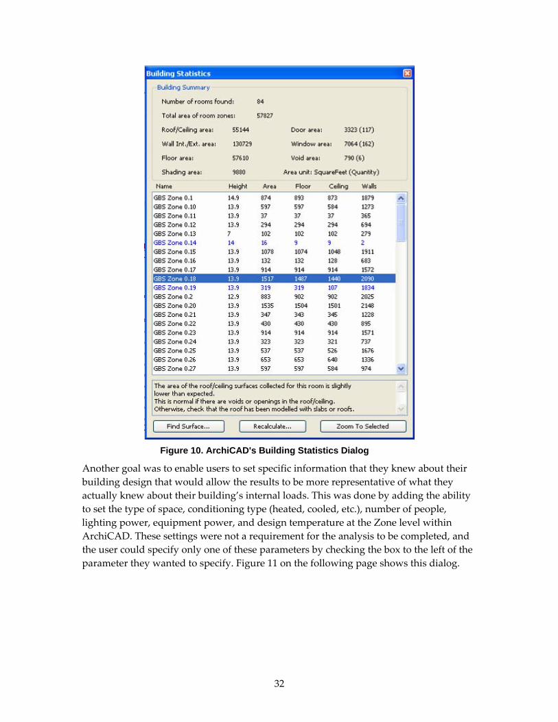
32
Figure 10. ArchiCAD's Building Statistics Dialog
Another goal was to enable users to set specific information that they knew about their building design that would allow the results to be more representative of what they actually knew about their building’s internal loads. This was done by adding the ability to set the type of space, conditioning type (heated, cooled, etc.), number of people, lighting power, equipment power, and design temperature at the Zone level within ArchiCAD. These settings were not a requirement for the analysis to be completed, and the user could specify only one of these parameters by checking the box to the left of the parameter they wanted to specify. Figure 11 on the following page shows this dialog.

33
Figure 11. ArchiCAD's GBS Space Properties Dialog
3.2.4. CAD Vendor gbXML Efforts
Participating CAD Vendor’s efforts were a key part of this objective successfully being met. Autodesk has incorporated gbXML functionality in two of its products; Autodesk Revit and Autodesk Building Systems. Not only has Autodesk developed gbXML functionality into its products, they have begun marketing this functionality and the Green Building Studio to their users.
Bentley has indicated to their users that their gbXML enabled applications will be released in 2008.
In Figure 12, the gbXML Export option is highlighted on Revit’s File Menu, and in Figure 16, is the gbXML export window for Building Systems.
These CAD vendors are only meeting the gbXML plug‐in requirements outlined below rather than the entire portion mentioned earlier in the report.

34
• Run on CAD platform – Each plug‐in development must be able to run on the same operating systems that the CAD tool supports.
• Derivation of thermal model – Ability of the plug‐in to automatically extract the thermal model from the CAD model.
• Building type and location – Ability of the plug‐in to require the user to specify the building type and its location via a postal code.
• Save gbXML file – The ability for the user to work offline and save the resulting gbXML file locally. This requirement was optional and dependant on the budget available.
Figure 12. Autodesk Revit gbXML Export Menu

35
Figure 13. Revit System's Space Internal Loads Dialog

36
Figure 14. Revit System's gbXML Settings Dialog

37
Figure 15. Revit System's gbXML Import Menu
Figure 16. Autodesk Building Systems gbXML Export Window
38
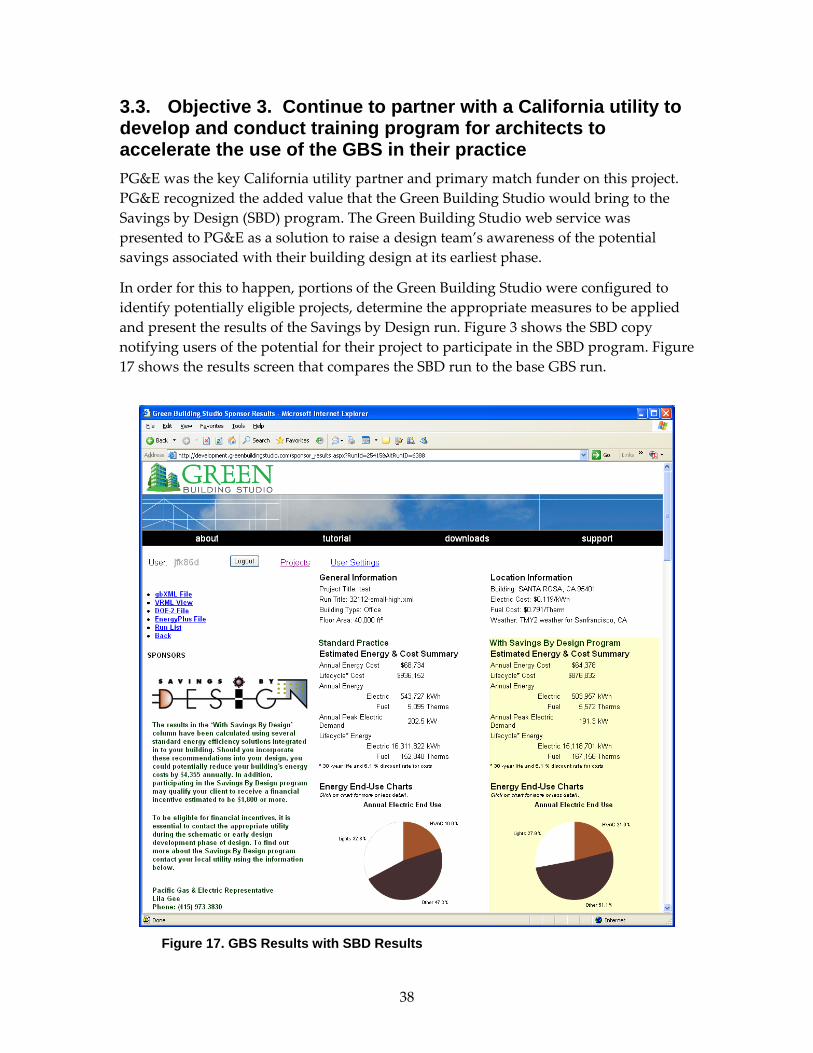
3.3. Objective 3. Continue to partner with a California utility to develop and conduct training program for architects to accelerate the use of the GBS in their practice PG&E was the key California utility partner and primary match funder on this project. PG&E recognized the added value that the Green Building Studio would bring to the Savings by Design (SBD) program. The Green Building Studio web service was presented to PG&E as a solution to raise a design team’s awareness of the potential savings associated with their building design at its earliest phase.
In order for this to happen, portions of the Green Building Studio were configured to identify potentially eligible projects, determine the appropriate measures to be applied and present the results of the Savings by Design run. Figure 3 shows the SBD copy notifying users of the potential for their project to participate in the SBD program. Figure 17 shows the results screen that compares the SBD run to the base GBS run.
Figure 17. GBS Results with SBD Results

39
The specific objective is to use GBS to reduce the cost of whole building projects and increase the number of whole building projects in the Savings by Design program.
For many years, California’s Investor Owned Utility implemented (IOU) “Savings by Design” (SBD) and “Energy Design Resources” (EDR) Programs have wrestled with the challenge of encouraging whole‐building energy analysis as a part of new building design. Indeed, these programs, working in concert with Title‐24, deserve much of the credit for the steady increases that have occurred in the efficiency of California’s non‐residential construction stock. Despite these advances, California’s Public Utilities Commission (CPUC) has continued to press the IOU’s to deliver a greater proportion of “Whole Building Analysis” projects under the SBD program. Without new tools to make the whole process easier, it is hard to imagine how the utilities might achieve that lofty goal. The Green Building Studio web service is designed to do exactly this – facilitate the whole building energy analysis process.
3.4 Objective 4. Implement a business plan that begins generating revenue from the GBS that is projected to sustain the GBS web service When the Green Building Studio web service was launched it was absolutely free for anyone to use. The intent was to remove any barrier from a large number of architects from using the service. It was determined that the perceived cost barrier in the market was not as large as the education barrier related to two items. First, even though an architect may be using one of the compatible BIM applications does not mean they know how to use it properly. Numerous models were submitted that were just plain wrong or incomplete. Second, architects are not trained to use energy use in the decision process, so most do not know what to do even when they get a result. Given these training challenges and operational and staffing costs we were tasked with hiring a business consultant to assist in determining a viable revenue model to sustain the GBS web service.
In order to provide this service for free, Green Building Studio, Inc., needed to develop a revenue model that would generate sufficient funds to pay for the operations and maintenance costs of the Green Building Studio. The model developed is to allow Building Product Manufacturers (BPMs) to advertise on the Green Building Studio website in a very unique and cost effective manner. Green Building Studio, Inc., built the Product Advisor into the Green Building Studio to serve up relevant building products that are specifically targeted to GBS users and their specific buildings. This allows BPMs to only pay for specific product ads to be seen and clicked on by exactly who they want. GBS users can also authorize their building and contact information to be shared with the BPM, who then pays for this highly qualified lead. This business model taps into the $5.5 billion dollars spent each year by BPMs to market and sell their products to the commercial building new construction market.
Copernican Group was hired to review our service value proposition, identify the

40
potential market size for such a service, and make recommendations on how to sustain the GBS web service. Copernican Group determined the following value proposition for the GBS web service.
1. Evaluating energy use earlier in the design process lowers design costs overall. It saves time and this money to modify a design earlier in the design process than later.
2. By developing an energy analysis directly from CAD data, GBS allows its users to experiment with design alternatives and receive rapid feedback on their energy use.
3. Productivity through “Interoperability” – This means the ability of the same data to be used at different phases of the design‐build cycle. For example, without GBS, a user would have to key in the relevant data to DOE‐2. Once a designer has uploaded a design to GBS, it could be redistributed to other kinds of users electronically. For example, a HVAC engineer could look at an uploaded drawing and begin working on that part of the process without receiving paper documents and keying in data. This reduces errors and time.
4. Connection with the manufacturers. Advertisers could develop targeted ads for GBS users. Then, designers might not have to use a general catalog like McGraw‐Hill’s “Sweet’s” product and search for equipment; the equipment manufacturers would seek them out. In later versions, manufacturers could, for example, suggest products that could improve the energy efficiency of the design or lower its cost.
They estimated the market size for energy efficiency software to be approximately $50 million per year and that an advertising model will not work for the service. Their recommendations for revenue models that may assist in sustaining the GBS web service are as follows:
1. Offer Premium Services
a. Allow users to try the service for free, and then require fees for additional projects or runs.
b. Rather than advertising, offer BPMs targeted sales tools based on the GBS web service.
2. Consider using Google AdSense on the service.
3. Evangelize whole building energy analysis by refining messaging and expanding online presence.
4. Research how existing users are using the tool and why some users do not fully use the service. Remove any barriers that are found.
We have implemented their first recommendation and enabled users to get five free runs

41
for every new project and then pay about $0.50 per space for each run on that project thereafter. We have also been successful in selling BPM sales tools to Owens Corning and United Technologies as well.
Green Building Studio, Inc., anticipates it will take 18 to 30 months before this revenue model generates sufficient revenue to pay for the operational and maintenance costs of the Green Building Studio.
3.5 Objective 5. Continue to encourage the development of gbXML as a non-proprietary standard for exchanging high-level design information between CAD tools and energy analysis tools The previous CDEAT project developed an XML schema called the Green Building XML schema (gbXML). This schema allows all the information necessary for conducting green building analyses, including whole building hourly simulations, to be contained in a computer readable and understandable format. During that project Trane enabled their TRACE 700 software application to read in gbXML files.
Trane has continued to push its gbXML support and is supporting more of the schema including export capabilities as seen in Figure 18.
Figure 18. Trane TRACE 700 gbXML Feature
In June 2004, Carrier, York International, Elite Software, ECOTECT, and Energy Soft indicated they will be supporting gbXML in the next releases of their software. This is a huge milestone for the HVAC design industry. For the first time the leading HVAC sizing software providers will be standardizing on a file format that has the intelligence required for eliminating the geometric take‐off task associated with all HVAC and building energy related engineering software. The introduction of gbXML has eliminated much of the redundant and error prone tasks that are so common in the AEC industry.

42
With the announcements made by the HVAC software industry and the current functionality the Green Building Studio has become a central point for all the design team to share building design information related to building energy and resource use as well as engineering analyses. This is graphically represented in Figure 19. The arrow heads indicate the direction of data transfer and a dashed line indicates that connection has been announced but has not been delivered to the market.
Figure 19. gbXML Compatible Applications

43
4.0 Conclusions and Recommendations The major conclusions and recommendations of this project are presented below.
4.1. Major Conclusions By making it easier for architects to produce designs that are energy and resource efficient, the Green Building Studio has laid a foundation for changing the way buildings are designed. The Green Building Studio has been used by a wide variety of architectural and engineering firms, both large and small, with some initial success. These results inspire Green Building Studio, Inc., to continue to refine the tool, incorporating what we have learned from these users. Mario Guttman of HOK, who participated in the beta test as well as the PG&E sponsored pilot user study, said, “I would like to see this real application continue to exist because it is what architects are asking for.”
As of January 2007, 48% of the projects entered are at the schematic phase or earlier. The majority, 62%, of the over 4,500 Green Building Studio registrants are using a BIM application that will work with the Green Building Studio and 37% are using either Revit or ArchiCAD. We will continue working with the remaining CAD vendors to ensure their products become gbXML enabled as well. Architects comprise 46% of the intended user base of Green Building Studio with the next largest group, 21%, being engineers. Green Building Studio, Inc., is very pleased to see that the intended audience for Green Building Studio represents the largest user base.
The majority of ADT, Revit, and ArchiCAD users are still learning the proper way of modeling a building to take advantage of integrated analysis solutions such as the GBS. An example of this is that a large number of users do not place floors in their models as it has not been required in 2D drawings. Even 3D drawings do not require a floor object to have a rendering completed. These types of misunderstandings have to be overcome to ensure complete and accurate models are built that can take full advantage of solutions such as the GBS. CAD vendors are testing the waters of these integrated analysis solutions and trying to determine how far they should support them based on user feedback. Early indications are very promising as a recent industry press article in Cadalyst indicates, “Exciting things are happening in the world of 3D CAD and BIM, and Green Building Studio, Inc.’s tools and enhancements to BIM are a significant part of that, and a product of the movement to realize the potential of BIM.”
There is still significant work to be done with the Green Building Studio to allow the market to embrace this groundbreaking technology as the early‐stage solution for cost‐effective energy efficient building design.
Green Building Studio, Inc., and its industry partners anticipate that between 12 to 24 months are needed for this service to begin generating revenue from advertising/lead generation. It is also anticipated that the Green Building Studio will be self‐sustaining with these revenues between 18 and 30 months from launch.

44
4.2. Commercialization Potential The Green Building Studio web service was launched in April 2004 and currently has over 4100 registered users. In 2006, we signed our first Building Product Manufacturer, PPG, to list their Solarban 70XL product in the design alternative screen. Green Building Studio, Inc., and its industry partners anticipate that between 12 to 24 months are needed for this service to begin generating revenue from advertising/lead generation. It is also anticipated that the Green Building Studio will be self‐sustaining with these revenues between 18 and 30 months from launch.
Green Building Studio, Inc., is actively seeking funding to ensure there is sufficient revenue to sustain the current operations associated with the Green Building Studio. Green Building Studio, Inc., has approached the Emerging Technologies Coordinating Council (ETCC), the logical early‐stage funding organization for GBS, but it has indicated that it cannot fund software related solutions as the California Public Utilities Commission has encouraged its focus to be primarily on hardware solutions. Energy Commission staff have been instrumental in suggesting alternative approaches to funding including their recommendation to participate in the Environmental Business Cluster. We are also actively soliciting additional funding through appropriate federal and energy agencies throughout the United States.
Green Building Studio, Inc., has been working with the Environmental Business Cluster for over a year to develop its business model, investor‐focused executive summaries, and the key selling points for various investor presentations. We have had success in attracting interest from several investment organizations, all of which are waiting to see revenue generated from the service prior to considering investment.
4.3. Benefits to California The objectives of this project to increase the adoption of whole building energy analysis in architectural design by 50% in the first two years and double by year four, and reduce the time building data take‐offs for team collaboration for energy code compliance, HVAC design, and energy analysis by 60%. This would provide California an average energy savings of 49 GWh/year over the next 9 years. The assumptions used in this estimation are provided in the Table 1 below.
Table 1 - Estimates of Electric Savings Due to GBS
Added Commercial Advanced Simulation Ave. Elec. Existing Approach GBS Approach Addl. Savings Year Load (GWh)2 Use3 Savings4 Savings (GWh) Savings (GWh) Due to GBS (GWh) 2003 3,519 15% 20% 106 0 0
2. California Energy Demand Forecast 2002‐2012 “business as usual” case, Docket # 99‐CEO‐1 3. Percent NRNC by floor area using Whole Building Approach in the SBD program, “NRNC MARKET CHARACTERIZATION AND PROGRAM ACTIVITIES TRACKING REPORT,” March 2002 4. Impacts of DOE‐2 based on user survey. (http://gundog.lbl.gov/dirsoft/d2whatis.html#Impacts of DOE‐2)

45
2004 3,482 20% 20% 104 104 0 2005 2,715 23% 20% 81 109 27 2006 2,189 25% 20% 66 101 35 2007 1,983 30% 20% 59 99 40 2008 1,727 35% 20% 52 104 52 2009 1,789 35% 20% 54 125 72 2010 1,956 35% 20% 59 137 78 2011 1,769 35% 20% 53 124 71 2012 1,693 35% 20% 51 119 68
Averages 64 113 49
As of March 2007, over 135 projects located in California have begun using the GBS for whole building energy analysis. Over 52 of the 135 project located in California were entered in 2006. In 2002, only 51 California projects participated in the Savings by Design whole building approach. Green Building Studio, Inc., is excited by these numbers and that it was able to meet the SBD amount in 2002 after only two years in the market and essentially no marketing. We are confident that GBS will be able to achieve its objectives with additional development and marketing support from the Commission and the California Investor Owned Utilities.
4.4. Recommendations Recommendations for future action are organized below. Actions that Green Building Studio, Inc., should take are listed first, followed by actions the CAD partners should take, and the actions the Energy Commission’s PIER program should consider in its role as a supporter of energy‐related research and development for the benefit of California. Finally, recommended actions by other parties are suggested.
Recommended Green Building Studio, Inc., Actions:
• Continue limited support of the Green Building Studio as resources allow.
• Continue seeking additional funding for the operations and further development of the Green Building Studio.
• Explore forming an industry consortium to fund Green Building Studio operations over the next two years.
• Solicit sponsors to fund an educational version of the GBS web service for all architectural design and engineering schools to use for free in their coursework.
• Continue outreach and technical support to CAD vendors to encourage implementation of gbXML export capabilities.
• Continue outreach and technical support to vendors of HVAC analysis tools, code compliance tools, and other applications downstream of the GBS to encourage implementation of gbXML import capabilities.

46
• Continue to encourage progress in the development of software interoperability standards in the A/E/C industry specifically the gbXML schema.
Recommended CAD Partner Actions:
• Continue marketing of the Green Building Studio.
• Provide training on how to effectively use their products with the Green Building Studio.
• Continue and further support the gbXML schema across architectural and engineering focused product lines.
• Assist in setting up the GBS web service for all architectural design and engineering schools to use for free in their coursework.
Recommended Energy Commission Actions
• Encourage the California Public Utilities Commission to recognize the enormous need to reeducate architects and building designers to use whole building energy analysis on their building designs and further insist that this become a requirement.
• Recommend Green Building Studio web service to those inquiring about a solution for conducting whole building energy analyses at the individual building, municipal, state, province, or country level.
Recommended Actions by Others
• AEC 3D‐CAD Vendors – Register and download the Software Developer’s Kit and begin working with Green Building Studio, Inc., and gbXML (www. greenbuildingstudio.com & www.gbxml.org).
• Building Products and Equipment Manufacturers – Contact Green Building Studio, Inc., about the highly targeted advertising and lead generation features of the Green Building Studio.
• AEC 3D‐CAD End Users – Register today and begin using the Green Building Studio on all your projects. (www.greenbuildingstudio.com)
• Other R&D Organizations – Contact Green Building Studio, Inc., to find out more about the Green Building Studio and the next phase of planned research and development.

47
5.0 Glossary
ABS. Autodesk Building Systems ABS is a 2D/3D‐CAD architectural design/modeling software targeted to engineers and is developed by Autodesk, Inc.,
ADT. Architectural Desktop ADT is a 2D/3D‐CAD architectural design/modeling software developed by Autodesk, Inc.,
AEC. Pertaining to the building‐related industries of Architecture, Engineering, and Construction.
aecXML. The aecXML schema is an XML vocabulary that is specific to A/E/C industries. It is a means of describing and sharing data with others in the A/E/C community, including: architects, engineers, contractors, owners/operators, estimators, consultants, materials suppliers, building product manufacturers, and others. One of the many features that makes aecXML so useful is its capacity to use existing software and databases to exchange information. (http://www.iai‐na.org/domains/aecxml.html)
ASP. Application Service Provider ‐ A model of software delivery where consumers pay a periodic fee in exchange for a license to use a specific software program that is hosted/maintained on a website (instead of on the end userʹs hard disk).
BS‐8. A project of the International Alliance for Interoperability (IAI). It is developing the Industry Foundation Classes (IFC) schemata for Heating Ventilation and Air‐Condition (HVAC), and allow interoperability between building performance simulation tools. The project is based at the Building Technologies Department of the Lawrence Berkeley National Laboratory. (http://eetd.lbl.gov/btp/iai/bs8/)
Building. As defined by the EAM, a building is a collection of spaces and surfaces.
CAD. Computer‐aided design.
Campus. As defined by the EAM, a campus is a collection of buildings that have some relationship to them.
DesignWorkshop. A family of 3D modeling software tools developed by Artifice, Inc., designed to integrate with drafting software, on both Windows and Macintosh platforms. (http://www.artifice.com/dw.html)
DOE‐2. An hourly, whole‐building energy analysis program, developed by the Department of Energy, which calculates energy performance and life‐cycle cost of operation. (http://simulationresearch.lbl.gov/)
EAM. Energy Analysis Module. EAM is the web‐based energy analysis software developed by Green Building Studio, Inc., under the CDEAT project with funding from the California Energy Commission Public Interest Energy Research program.
EAP. Energy Analysis Preprocessor. The EAP is software developed by Artifice, Inc., to

48
prepare DesignWorkshop files for energy analysis by the EAM and translate CAD data into gbXML format. The EAP was developed independently without PIER funding.
ETCC. Emerging Technologies Coordinating Council. The ETCC was established under the auspices of the California Public Utilities Commission (Public Goods Charges) to seek opportunities to coordinate efforts between each of the California investor owned utilities’ emerging technologies programs and the Energy Commission’s PIER program.
EnergyPlus. The Department of Energy’s latest building energy simulation software program. EnergyPlus is a stand‐alone simulation engine without a ʹuser friendlyʹ graphical interface. It reads input and writes output as text files. The GBS web service now provides EnergyPlus input files automatically with every run. (http://www.eren.doe.gov/buildings/energy_tools/energyplus/)
GBS. Green Building Studio web service (www.greenbuildingstudio.com) that hosts the EAM software.
gbXML. An industry supported XML Schema for containing building related data for conducting green, energy, and resource related analyses. Green Building XML data files are XML files, the structure of which is defined by the Green Building XML Schema (http://www.gbxml.org).
HVAC. Heating, Ventilation, and Air‐Conditioning.
HTML. Hyper Text Markup Language, the authoring language used to create documents on the World Wide Web.
IAI. The International Alliance for Interoperability. The IAI’s mission is to allow interoperability among work processes in the AEC industry by enabling all participants’ computer applications to share and exchange project information through entire project lifecycle (strategic planning, design, engineering, construction, operation). (http://www.iai‐international.org/iai_international/). The IAI North American chapter is a council of the National Institute of Building Sciences.
IFC. Industry Foundation Classes. A cross‐platform, vendor‐neutral standard, developed by the IAI, that allows architectural CAD users to transfer a complete, thorough, and accurate building data model from one CAD platform to another, with no loss of data. This format was reviewed early on in the EAM development and was found to be incomplete for the needs of the EAM. That continues to be the case today.
Interoperability. The ability of computer applications to share and exchange project information. In order for data transfer to work properly there needs to be an agreement on definitions of data. Two such exchange formats for buildings‐related data currently exist: aecXML and IFCs.
LBNL. Lawrence Berkeley National Laboratory (http://www.lbl.gov/). LBNL is host to the Simulation Research Group and is involved in the BS‐8 project of the International Alliance for Interoperability (IAI).

49
Mono‐planar model. As defined by the EAM, the mono‐planar model is a model of a building composed of planar surfaces that represent the actual volumetric elements of the building.
OEM. Original Equipment Manufacturer.
Opening. As defined by the EAM, an opening is a large penetration in a surface where a window, skylight, or a door may fit. An opening can also have nothing in it except air.
Plug‐in. A hardware or software module that adds a specific feature or service to a larger system. For example, there are number of plug‐ins for the Netscape Navigator browser that enable it to display different types of audio or video messages.
SDK. Software Developers Kit. The SDK for Green Building Studio, Inc.,’s EAM now includes: 1) the general development requirements needed to support the EAM, 2) the minimum gbXML elements that must be supported, 3) additional elements that may be supported to extend EAM functionality, 4) the EAM Application Programming Interface (API), 5) EAM object rules, 6) a discussion of simulation model development and model reduction theory, 7) a list of EAM components, and 8) a glossary. The SDK can be downloaded from Green Building Studio, Inc.,’s website
SOAP. Simple Object Access Protocol (http://www.w3.org/TR/SOAP). SOAP is a protocol for exchanging information. It is typically used to allow program functionality over the Internet in a cross‐platform manner. Free client‐side applications are available for CAD developers to use on most operating systems.
Space. As defined by the EAM, a space is a volume enclosed by many surfaces that is used as a room in a building.
Surface. As defined by the EAM, a surface is an opaque planar polygon that represents interior and exterior walls, ceilings, floors, slabs, roofs, and other opaque diaphragm type structures in a building.
TRACE. A software program developed by The Trane Company (a manufacturer of HVAC equipment) that models buildings, HVAC systems, and economic / utility scenarios. (http://www.trane.com/commercial/software/trace/)
VAR. Value‐Added Reseller.
VRML. Virtual Reality Modeling Language, a specification for displaying 3‐dimensional objects on the World Wide Web. It is often described as the 3‐D equivalent of HTML.
XML Schema. XML Schema (http://www.w3.org/XML/Schema) is an XML language that defines the structure of XML documents.
XML. Extensible Markup Language (http://www.w3.org/XML). XML is a format for structured data. XML is platform‐independent and is in plain text. XML is similar to HTML, except that tags are customized for a specific application. The tag names and

50
format of this data can be defined using XML Schema language.

51
Appendix A - Executive Order S-20-04

52

53
EXECUTIVE ORDER S-20-04 by the
Governor of the State of California
WHEREAS, the Energy Action Plan adopted by the state's energy agencies places conservation and energy efficiency first in the loading order of energy resources because they are the least expensive and most environmentally protective resources; and
WHEREAS, commercial buildings use 36 percent of the state's electricity and account for a large percentage of greenhouse gas emissions, raw materials use and waste; and
WHEREAS, the U.S. Green Building Council's Leadership in Energy and Environmental Design (LEED), the nation's leading green building rating system, promotes "high performance" building practices; energy, water and materials conservation; environmentally preferred products and practices; improvements in employee health, comfort and productivity; and reductions in facility operation costs and environmental impacts; and
WHEREAS, electricity costs for California's commercial and institutional buildings exceed $12 billion per year, and cost-effective efficiency practices outlined in this Order can save more than $2 billion per year; and
WHEREAS, the state's own buildings consume over $500 million of electricity per year, and the measures outlined in this Order can save California taxpayers $100 million per year; and
WHEREAS, high-performance schools also reduce energy and resource consumption, while creating safer and healthier learning environments; and
WHEREAS, investments in energy efficiency measures provide high returns on investment and boost California's economy, creating more jobs, local spending and tax revenue.
NOW, THEREFORE, I, ARNOLD SCHWARZENEGGER, Governor of the State of California, by virtue of the power vested in me by the Constitution and statutes of the State of California, do hereby order effective immediately:
1. That the state commit to aggressive action to reduce state building electricity usage by retrofitting, building and operating the most energy and resource efficient buildings by taking all cost-effective measures described in the Green Building Action Plan for facilities owned, funded or leased by the state and to encourage cities, counties and schools to do the same.
2. That state agencies, departments, and other entities under the direct executive authority of the Governor cooperate in taking measures to reduce grid-based energy purchases for state-owned buildings by 20% by 2015, through cost-effective efficiency measures and distributed generation technologies; these measures should include but not be limited to:
2.1. Designing, constructing and operating all new and renovated state-owned facilities paid for with state funds as "LEED Silver" or higher certified buildings; and
2.2. Identifying the most appropriate financing and project delivery mechanisms to achieve these goals; and
2.3. Seeking out office space leases in buildings with a U.S. EPA Energy Star rating; and
2.4. Purchasing or operating Energy Star electrical equipment whenever cost-effective.

54
3. The Division of the State Architect in the Department of General Services should adopt guidelines by December 31, 2005, to enable and encourage schools built with state funds to be resource and energy efficient.
4. That the California Public Utilities Commission (CPUC) is urged to apply its energy efficiency authority to support a campaign to inform building owners and operators about the compelling economic benefits of energy efficiency measures; improve commercial building efficiency programs to help achieve the 20% goal; and submit a biennial report to the Governor commencing in September 2005, on progress toward meeting these goals.
5. That the California Energy Commission (CEC) propose by July 2005, a benchmarking methodology and building commissioning guidelines to increase energy efficiency in government and private commercial buildings.
6. That the CEC undertake all actions within its authority to increase efficiency by 20% by 2015, compared to Titles 20 and 24 non-residential standards adopted in 2003; collaborate with the building and construction industry state licensing boards to ensure building and contractor compliance; and promptly submit its report as per Assembly Bill 549 (Statutes of 2001) on strategies for greater energy and peak demand savings in existing buildings.
7. The California Public Employees Retirement System and State Teachers Retirement System are requested to target resource efficient buildings for real estate investments and commit clean technology funds to advanced sustainable and efficiency technologies.
8. Other entities of state government not under the Governor's direct executive authority, including the University of California, California State University, California Community Colleges, constitutional officers, legislative and judicial branches, and CPUC, are requested to actively participate in this effort.
9. Nothing in this Order shall be construed to confer upon any state agency decision-making authority over substantive matters within another agency's jurisdiction, including any informational and public hearing requirements needed to make regulatory and permitting decisions.
10. Commercial building owners are also encouraged to take aggressive action to reduce electricity usage by retrofitting, building and operating the most energy and resource efficient buildings by taking measures described in the Green Building Action Plan.
11. This Order is not intended to, and does not create any rights or benefits, substantive or procedural, enforceable at law or in equity, against the State of California, its departments, agencies, or other entities, its officers or employees, or any other person.
12. That as soon as hereafter possible, this Order shall be filed with the Office of the Secretary of State and that widespread publicity and notice shall be given to this Order.
IN WITNESS WHEREOF I have here unto set my hand and caused the Great Seal of the State of California to be affixed this the twenty-seventh day of July 2004. /s/ Arnold Schwarzenegger Governor of California

55
Appendix B - GBS Specification

56

57
Green Building Studio
Design Alternatives
Requirement Spec
Version .23 June 2, 2005
GeoPraxis, Inc.
Copyright © 2005 GeoPraxis, Inc. ALL RIGHTS RESERVED

58
Table of Contents
1.1. Background and Overview ..................................................................................................... 7 1.2. Project Objectives ...................................................................................................................... 8
1.3. Report Organization ................................................................................................ 8
2.1. Requirements ........................................................................................................... 9 2.1.1. Key Update Requirements ..................................................................................................... 9 2.1.2. GBS Web Service Requirements .......................................................................................... 10 2.1.3. gbXML Plug-in Requirements ............................................................................................. 11
2.2. Specifications .......................................................................................................... 12
Add Design Alternative Runs Page ................................................................................... 13 2.2.1. Elements ............................................................................................................................ 17 2.3. Test Plan Development ............................................................................................................. 18
2.3.1. Software Development (Tasks 3) ....................................................................... 18
2.3.2. Beta Testing (Task 4) ............................................................................................. 19
2.3.3. Identify Alternative Business Strategies (Task 5) .......................................... 21
2.3.4. Regional, National, and global Match Activities (Task 6) ............................ 22
3.1. Objective 1. Build upon past work to enhance the GBS to ensure it can assist architects in cost effectively achieving the LEED goals as outlined in California’s Executive Order S-20-04 .............................................................................. 23
3.1.1 Green Building Studio Design Alternatives ......................................................................... 23
3.2. Objective 2. Continue to partner with CAD vendors to further integrate this functionality into their current CAD tools .............................................................. 25
3.2.1. gbXML Plug-ins ................................................................................................................... 25 3.2.4. CAD Vendor gbXML Efforts ............................................................................................... 33
3.3. Objective 3. Continue to partner with a California utility to develop and conduct training program for architects to accelerate the use of the GBS in their practice .................................................................................................................................... 38
3.4 Objective 4. Implement a business plan that begins generating revenue from the GBS that is projected to sustain the GBS web service ............................. 39
3.5 Objective 5. Continue to encourage the development of gbXML as a non-proprietary standard for exchanging high-level design information between CAD tools and energy analysis tools ........................................................................................ 41
4.1. Major Conclusions ................................................................................................. 43
4.2. Commercialization Potential ............................................................................... 44
4.3. Benefits to California ............................................................................................. 44
4.4. Recommendations ................................................................................................. 45 Introduction ...................................................................................................................... 62
Program Requirements .................................................................................................... 62

59
Functional Requirements ........................................................................................................ 62 User Interface ...................................................................................................................................... 62 User Experience ................................................................................................................................... 62 Session Time Out ................................................................................................................................. 62
Platform Requirements ........................................................................................................... 62 Server Platform .................................................................................................................................... 62 Client Platform .................................................................................................................................... 63
Program Objectives .......................................................................................................... 64
Current Solution ...................................................................................................................... 64
Design Alternative Enhancement ........................................................................................... 65
Additional GBS Enhancements .............................................................................................. 65 Program Overview............................................................................................................ 67
Basic Design ............................................................................................................................. 67
Program Flow Diagrams ......................................................................................................... 68
Basic Program flow ................................................................................................................. 69
User Design Alternative Web Page Flow ............................................................................... 70
Sponsor Run Page Flow .......................................................................................................... 71
Add Sponsor Product Parameters ......................................................................................... 73
Windows Service and process flow ........................................................................................ 74
Database ................................................................................................................................... 76 Web Pages ........................................................................................................................ 84
Site GUI Requirements ........................................................................................................... 84 Font ...................................................................................................................................................... 84 Format Style ........................................................................................................................................ 84 Navigation ........................................................................................................................................... 85
Run List Page ........................................................................................................................... 86
Add Design Alternative Runs Page ........................................................................................ 91
Manage Design Alternative Groups ....................................................................................... 97
The Design Alternatives columns above will be organized on tabs to ensure space is used effectively.Sponsor Design Alternatives Process ................................................................. 100
Sponsor Design Alternatives Process ................................................................................... 101
Sponsor Ad Display ............................................................................................................... 102
Select base runs for Sponsor Design Alternatives .............................................................. 104
New Project Page ................................................................................................................... 107
Display runs relative to baseline .......................................................................................... 110
Sponsor Ad Setup – page 1 .................................................................................................. 112
Sponsor Ad Setup - page 2 .................................................................................................... 114
Sponsor Rep List ................................................................................................................... 116
60
Sponsor Rep Assignment ...................................................................................................... 118 Conventions Used in This Document ............................................................................ 129
Format Styles ......................................................................................................................................129 Data Types ..........................................................................................................................................129
Introduction .................................................................................................................... 130
What is the Energy Analysis Module? ................................................................................. 130 Development Requirements ........................................................................................... 131
Operating Systems ................................................................................................................. 131
3D-CAD Application Requirements .................................................................................... 131
Developer Tools ..................................................................................................................... 131 XML Editor ........................................................................................................................................131 VRML browser plug-in ......................................................................................................................131
Basic Program Flow .............................................................................................................. 133 Energy Analysis Module API ........................................................................................ 134
Overview ................................................................................................................................. 134
EAM Functionality ................................................................................................................ 134 User Login ..........................................................................................................................................134 List User’s Projects .............................................................................................................................134 List User’s Project Runs .....................................................................................................................134 Request Energy Results for a New Run ..............................................................................................134 Request Energy Results for an Existing Run ......................................................................................135
Functions ................................................................................................................................ 139 Initialize .........................................................................................................................................139 ListProjects ..................................................................................................................................139 ListRuns .........................................................................................................................................139 NewRun ..........................................................................................................................................140 GetResults ....................................................................................................................................141
XML Schema Support .................................................................................................... 142
Minimum Element Support .................................................................................................. 142 <gbXML> ...........................................................................................................................................142 <Campus> .........................................................................................................................................143 <Building> ....................................................................................................................................145 <Space> ...........................................................................................................................................146 <Surface> .......................................................................................................................................152 <Opening> .......................................................................................................................................155 <PlanarGeometry> ..............................................................................................................................157 <PolyLoop> ........................................................................................................................................158 <CartesianPoint> ................................................................................................................................158 <Coordinate> ......................................................................................................................................158 <RectangularGeometry> .....................................................................................................................158 <Results> ............................................................................................................................................159
EAM Object Rules .......................................................................................................... 162
Space ....................................................................................................................................... 162
Surface .................................................................................................................................... 162

61
Thermal Model Development ........................................................................................ 162
Overview ................................................................................................................................. 162
The Process ............................................................................................................................ 162 Take Offs ............................................................................................................................................162 Define Building Envelope and Constructions .....................................................................................163 Define Building Systems and Operation .............................................................................................165 Iterative De-bugging, Syntax and Error Checking ..............................................................................166
EAM Limits .................................................................................................................... 166
DOE-2 Limits .....................................................................................................................................166
Beta Test Report for .............................................................................................................. 171
Conceptual Design Energy Analysis Tool Phase III ........................................................... 171
Contract #: 500-04-020 .......................................................................................................... 171
January, 2007 ......................................................................................................................... 171 Contractor Project Manager: John Kennedy .......................................................................................171 Commission Project Manager: Norm Bourassa ..................................................................................171
Introduction .................................................................................................................... 171
Testing Methodology ...................................................................................................... 171
Components tested. ............................................................................................................... 172
Tests Conducted .................................................................................................................... 172 Testing and Results ........................................................................................................ 173
Testing of Web Site ................................................................................................................ 173
Test Case Number: 5.2 .......................................................................................................... 173
New User Registration Page ................................................................................................. 173
Load Testing of Web Service ................................................................................................ 177
Simulation Testing ................................................................................................................. 177
Beta Testing ............................................................................................................................ 179
Current Outstanding Issues .................................................................................................. 180 Green Building Studio web site and service .......................................................................................180 Graphisoft ArchiCAD gbXML plug-in ..............................................................................................182 Autodesk Architectural Desktop gbXML plug-in ..............................................................................182

62
Introduction This is the specification document for Green Building Studio Design Alternatives. It is intended to be read by the programmers and engineers working on the project to give them a detailed understanding of the project they are building.
Program Requirements Functional Requirements The following are functional requirements of the Green Building Studio web service.
User Interface The user interface must be kept as simple as possible and require as few mouse clicks as possible to achieve the desired result.
The graphical elements of the user interface must be artistic in nature and have a simple clean quality to them.
User Experience The user’s experience must follow the following requirements. The response time for any user initiated activity should be as soon as possible. If the response time is anticipated to be greater than 15 seconds, the user should be presented with progress elements that will assist in giving the perception of reduced time. If the response time is anticipated to be greater than 30 seconds, the user should be presented with the option to be notified when the process is completed.
Session Time Out Session time outs should be set to 30 minutes.
Platform Requirements
Server Platform The Green Building Studio web service will run on any .NET capable Microsoft Windows server platform. Other requirements are listed below.
• SQL Server 2000
• IIS 6.0
• 2 GB of ECC RAM
• 80 GB HD RAID 5
• Nightly incremental backups
• Firewall sufficient for function of web service and remote management.

63
Client Platform The Green Building Studio service requires that the client platform be capable of the following requirements.
• Ability to make SOAP calls
• Ability to connect to the Internet
• A web browser that can display web pages complying with the HTML 4.0 standard and has JavaScript enabled
• Sufficient hardware and OS requirements for the client’s 3D-CAD application.
• Monitor resolution of 1024x768.
• Color requirements of at least 64k colors.

64
Program Objectives Current Solution GeoPraxis has developed the EAM module and integrated it into the Green Building Studio web service which allows a building designer to utilize the information that they have already entered into their 3D-CAD tool in designing their building to get accurate energy and resource use results for their building. To make this tool available and easy to use for building designers at any location, it is web-based, with functionality to support multiple users and projects online.
1. Architects register online, then login to access their projects, view energy results data, and manage member access to their projects.
2. Once registered Architects can access the site through a GeoPraxis provided or CAD-vendor provided gbXML plug-in.
3. Building Product Manufacturers can place ads for their products and specify the design criteria for those product ads to be displayed.
4. Sponsors/Utilities can login and audit usage at an aggregate level.
5. Present building energy & resource use values in a clear and concise way, and encourage 3D-CAD developers to present results on the model itself.

65
Design Alternative Enhancement
Green Building Studio currently provides energy usage analysis for a submitted building design. While this is very useful in and of itself, the GBS service will also provide the capability of adjusting various building design parameters to achieve the best combination of energy requirements and building design. Allowing a user to make modifications to their design and see the impacts associated with those modifications enables informed decisions to occur. Further, this is the most requested feature from the current set of GBS users.
Portions of this specification have funding sources secured and other portions currently do not. It is the intent of this document to ensure future funded portions seamlessly work with the portions that will be enabled in the near term.
Additional GBS Enhancements Several additional enhancements will be incorporated to the Green Building Studio service that is funded by the California Energy Commission. These are described below.
Title-24 2005 Data Modifications The underlying GBS data contained in the GBS database for California will be updated to include new values for the 2005 Title-24 energy code. Both commercial and residential code values will be incorporated. Further, the zip code mapping of the climate zones within California will also be updated.
If the energy code update requires any database structure changes those will be documented in this specification.
Enhanced Automated Zoning and System Assignments GeoPraxis will expand the current zoning capabilities of the Green Building Studio as well as address some known issues with smaller buildings. A threshold will be placed on smaller buildings to ensure zoning and system assignments correspond to system sizes that are available on the market. For instance, a small building with 12 rooms currently maybe zoned fairly extensively and has several systems whereas the same building may only have one zone and system serving it.
Enhancements to the materials and construction library GeoPraxis has been making a very significant push in the industry to standardize the way material and constructions data is stored in the CAD application as well as transmitted to downstream applications like the GBS.
GeoPraxis has received permission from ASHRAE to incorporate their material and construction library into the GBS. So, this enhancement will incorporate ASHRAE material and construction data into the GBS as well as gbXML.

66
Increased DOE-2.2 support Once of the main discrepancies in a DOE-2.2 file created by the GBS is the lack of 2D space polygon data. Although this has no impact on the energy results of the DOE-2.2 simulation it does impact the usability of the DOE-2.2 file in eQuest.
GeoPraxis will add support for the space 2D polygon as well as several code compliance keywords that will further streamline a user in using GBS-created DOE-2.2 files in eQuest for code compliance.
Increased EnergyPlus support GeoPraxis has developed support for EnergyPlus, but has not fully tested it nor updated the gbXML stylesheet to the latest version of EnergyPlus. GeoPraxis will extend the current stylesheet to support the same level of materials, constructions, internal loads and schedules, and HVAC equipment as the DOE-2.2 stylesheet.
Further, on the GBS results screen, a link to the EnergyPlus idf file will be provided. A small fee may be required for the user to download this file. This will be determined based on our outside consultant’s recommendation of such a fee.
Support for Single-family residential buildings The current version of the GBS is designed for primarily commercial buildings and multi-family residential buildings. Over the past year several architects have attempted to use the service for single-family residential buildings.
GeoPraxis will be enabling single-family residential buildings by adding them to the building type list as well as populating the GBS database with the necessary values for single-family residential buildings.

67
Program Overview
Basic Design GBS has been developed with Visual Studio .Net 2003, the latest web development environment from Microsoft. The web server is Microsoft IIS, and the back end database SQL Server 2000. The actual web pages are written in ASP.Net, and the development language is C#. C# was chosen because it is a full featured programming language directly related to C++ and Java, and it will provide maximum opportunity for scalability, maintainability, and enhancement. The system is deployed on multiple Windows Server 2003 systems in a hosted environment.
The solution is designed to be used by architects seeking to optimize building energy usage at the schematic phase of design. They can store projects online and invite project members to there GBS project.
A significant ad and lead channel has been enabled in the GBS for building product manufacturers (BPM) to present their ads to the ideal projects most suited for their products. When an architect’s design meets those parameters, their ad will be displayed on the results page for the project. The architect will then have the option of sharing their building information with the BPM or just review the BPM’s web site.
As part of the design alternatives feature the BPM will be allowed to have their products to become an option under the design alternative screen. This further adds immense value to the industry for the BPM to actually have their product analyzed on the actual building design in a very expedient way.

68
1. Program Specifications
Program Flow Diagrams In the following pages several flow diagrams illustrate the logic associated with various Green Building Studio design alternative operations.

69
Basic Program flow
In Figure 1, we have the basic program flow.
Figure 20 Design Alternative process This is a broad overview of the alternative runs process, showing new and existing pages. Each new page is discussed in detail subsequently. There are two basic avenues to add design alternatives: the user himself, or a product sponsor, who is enabled by the user.
Run List Page
Add Design Alternative Runs Page(new page)
Parameters:RoofWallGlazingGlazing FrameLighting TechLighting ControlsHVACSite GenerationRotation
If sponsor alt run, use sponsorparameters
Manage DesignAlternative Groups
(new page)
Design AlternativeResults Page(if sponsor alt run,uses sponsorstylesheet)
Cost infoDetailed
Ad click
Check SponsorRights
Sponsor receivesinvitation to join
project as sponsormember
Project Page
new fields:CountryProvince/CityUtilityScheduleWeather lookup
Show:Weather design
Regular RunResults Page
SponsorDesign Alt run
enabled?
yes
Assign base runsto sponsor
Sponsor joinsproject and logs in

70
User Design Alternative Web Page Flow The main goal of the design alternatives feature is to allow the user to quickly make modifications to their design and see the impacts of those modifications.
Figure 21 Web page flow
From the Run List page, the user can navigate to pages that add design alternatives, view results, or manage design alternative groups. Design alternative groups are sets of preselected parameters which can then be applied with one mouse click to a GBS run. Thus, the user could specify a group of parameters to process, and then save them for reuse. He could subsequently apply this group to multiple runs in multiple projects.
The alternative runs are added to the system alternative run queue, and then processed by the alternative run processor. The results are then viewable from the Run List page.
Run List Page
Add DesignAlternative Runs
Page
Manage DesignAlternative Groups
View Design Alternative Results

71
Sponsor Run Page Flow
The diagram below shows the process by which a BPM (sponsor) can add a design alternative run for a user, using the manufacturer’s own product. The user could then see the results.
As shown in the diagram, the user first clicks on the sponsor ad, which takes him to the 90/10 frameset with the sponsor web page above, and the sponsor design alternative request form below. The user then has the option of selecting one or more base runs for the sponsor to run design alternatives on, using the sponsor’s product. From then:
1. The sponsor administrator is notified of this request, which has been saved in the GBS database.
2. Using rules based automation; a sponsor employee is assigned the project.
3. Sponsor joins project, and when he logs into GBS the project shows up in his Run list
4. Only the assigned base runs are visible in the project’s run list, to which he then adds his sponsor-specific alternatives and adds to the system queue.
5. The alternative run processor detects these runs in the queue, and processes them
6. The results by default are visible only to the sponsor, in his run list.
7. He reviews the results, and has the option to then make the results visible in the other project member’s Run lists, with read-only or read and download (gbXML and DOE file) rights.
8. Once the sponsor makes the results visible to other users, they are identified by an icon to the left of the run title and a tool-tip with the sponsor’s name
9. The results are presented using the special style-sheet that has been set up for the sponsor.

72
Figure 22 Sponsor web page flow
Click on Sponsorad
User can seeresults of Sponsordesign alternativerun with sponsor’sstyle sheet applied
User selects baseruns for sponsor to
use
View frameset withsponsor url (90%)and sponsor altrun form (10%)
Sponsor assigneejoins project, logsin , and sees onlythose runs he was
assigned.
Sponosradministrator is
notified
Sponsor adds hisalternatives usinghis own products
By default, theresults are only
visible inSponsor’s runlist.
Sponsor can makethese results
visible in User’srunlist, with read-only or read-only
and downloadrights
A rules-based,automated
mechanism will beused to assign
specific projects
Let sponsor rundesign alternativeusing sponsor’s
products?
Sponsor reviewsresults in his
runlist, with hisstylesheet applied

73
Add Sponsor Product Parameters
Figure 23 Add Sponsor design alternatives to standard design alternatives The sponsor will have the ability to do design alternative runs using the specific parameters that have been added to the database. He will be able to try out his products on the building design, with the results available for the building design team to review. The results can be displayed using a custom stylesheet that was developed specifically for their product.
Make gbXmlconstruction
Get detailed specinformation for
sponsorparameters
Add Sponsor results stylesheet to sponsor table (with new field ‘Stylesheet’)

74
Windows Service and process flow
There will be a windows service which periodically checks for design alternatives in the database that need to be run. If so, it will call a .Net class written in C# that will do the processing and update the database. That class could be instantiated by EAM and called via EAMplex as well, which would also make it scalable for multiple servers. The service will retrieve queued runs with priority given to runs by Users who are paying a subscription fee. This category also includes sponsor design alternative runs. Regular user runs will be processed after the priority runs, and with a specific daily run limit.
The alternative run processing will take place on the same servers as the regular run processing, so care must be taken to allow for time for the regular runs.

75
Figure 24 This is the underlying process flow that would run the design alternatives and get the results.
Add designalternative to
Alternatives table,from GBS site
Windows servicecontinually checks
for alt runs thatwere assisgned
Alternatives table
This can be scaledfor multiple servers
using the samealgorithm asregular runs
Alt to run?
Regular run in last15 seconds on
server?Wait 15 seconds
Yes
Wait periodNoProcess alt run,
update alt table
Get pending runlist, with priorityuser runs first
Priority user?
Yes
Exceeded dailyquota?
No
Yes
No
YesNo

76
Database Below is the database schema for Green Building Studio alt design lookup tables.
Figure 25 Database schema
AltParamType
PK AltParamTypeID
NamerefTablerefIDColCalcPriorityCalcMethodCostCalcMethod
AltParamValue
PK AltParamValueID
AltParamTypeIDDescValueOrdergbXmlCostECRIDSponsorID
SoapProc
PK SoapProcID
WebAddressAltParamTypeID
SoapParam
PK SoapParamID
SoapProcIDParam
AltParamCompoundType
PK AltParamCompoundTypeID
AltParamCompoundIDAltParamTypeID
AltParamCompound
PK AltParamCompoundID
Name
AltParamCost
PK AltParamCostID
AltParamValueIDNameCostUnitReference
AltParamValueUserCost
PK AltParamValueUserCostID
AltParamCostIDProjectID

77
AltParamType fields:
• Name - The display name of the parameter type:
o Roof, Wall, Glazing, Glazing Frame, Lighting Tech, Lighting Controls, HVAC Systems, Site Generation, Rotation are what we are starting with.
• RefTable – A lookup table, for example, ‘Constructions’
• RefIDCol – A column in the lookup table, such as ‘id’
• CalcPriority –The order in which this needs to be calculated, relative to other parameters
• Calc Method – This will be an enum which will map to a special class for each type of parameter, which will do the actual calculation.
• CostCalc Method – This will be an enum which will map to a special class for each type of parameter, which will do the actual cost calculation
AltParamValue fields:
• AltParamTypeID – links to the type
• Desc – Display name for the parameter
• Value – RefIDCol in a lookup by the RefTable, as determined in the AltParamType table
• Order – Display order
• gbXML – If this is a sponsor added parameter, a prebuilt gbXML construction
• Cost, usually in $/sq. ft
• ECRID is an int, maps to the Energy Code Region table. This will give the option of code compliant mapping.
• SponsorID – Identifies the sponsor, if a sponsor parameter.
AltParamCompound - This is used to build up a multiple-type category
• Name
AltParamCompountType
• AltParamCompoundID – Links to the Compound parameter

78
• AltParamTypeID – links to the Type parameter. There are additional records for each AltParamType comprising the AltParamCompound
AltParamCost – provides cost info for selected parameters
• AltParamValueID – links to the AltParamValue
• Name
• Cost
• Unit
• Reference – source of cost
AltParamValueUserCost – for custom user cost
• AltParamCostID – links to the alt parameter being costed
• ProjectID – Project specific
There is an internal set of predefined design alternatives, and an open, external interface for custom design alternatives. These are accessed by a SOAP web service, taking an object array as input parameters and returning an xml document with parameter name, cost, gbXml.
SoapProc
• WebAddress – the SOAP procedure url
• AltParamTypeID – links to the AltParamType
SoapParam – The parameters for each Soap proc
• SoapProcID – links to the Soap proc
• Param – the specific parameter

79
Below are the lookup tables for the predefined design alternatives:
The lookup tables shown above will enable the selection of appropriate design alternative paramters based on ECR, building type, building size, and other parameters, using stored procedures.
Below is the schema for the alternative group tables
AltGroup
PK AltGroupID
UserIDSponsorIDAltGroupName
AltGroupParam
PK AltGroupParamID
AltGroupIDAltParamValueID
HVACParam
PK HVACParamID
NameECRIDBldgTypeBldgSizeLowBldgSizeHighHVACSystemID
LightingParam
PK LightingParamID
NameECRIDBldgTypeBldgSizeLowBldgSizeHighLightingID
LightingControlParam
PK LightingControlParamID
NameECRIDBldgTypeBldgSizeLowBldgSizeHighCeilingHtLightingControlID
ConstructionParam
PK ConstructionParamID
NameECRIDSurfaceTypeConstructionID
GlazingParam
PK GlazingParamID
NameECRIDGlazingID

80
Figure 26 schema for the alternative group tables
AltGroup fields:
• UserID – The UserID of the user who made the group
• SponsorID – The SponsorID of the sponsor Administrator who made the group (if a sponsor-made group)
• AltGroupName – The name of the group AltGroupParam fields:
• AltGroupID – The ID of the Alternative Group
• AltParamValueID – The ID of the alternative parameter value

81
Below is the Users table, with the SponsorID field added:
A Sponsor Administrator can invite Sponsor Users (who are sponsor employees) to join Green Building Studio. Embedded in their email invitation is the Administrator’s SponsorID which is saved in their new user record. The presence of the SponsorID will give them access to alternative parameters and alternative parameter groups which have been setup for them by their Sponsor Administrator.
Users
PK UserID
UsernameEmailFnameLnameTitleCompanyPhoneAddress1Address2CityStateCountryZipCodePasswordCO_LicenseIDlevelJobFunctionIDOrganizationTypeIDOrganizationSizeIDContactMethodIDDateAddedLicensePendingSponsorID
The SponsorID field has beenadded to the Users table

82
Below are the tables for Design Alternative Runs:
AltRuns
AltRunID
RunIDUserIDAltGroupIDUtilitySponsorIDTitleDateAddedStatusIDDetailedStatusNotifySimulationDateSimulationDurationSimulationOKResultsGeneratedAnnualElecUseAnnualElecDemandAnnualElecCostAnnualFuelUseAnnualFuelCostgbXMLreceivedgbXMLcleanedgbXMLFullDefaultsgbXMLpostEAMresultChartsBuildingTypeFloorAreaEUIRunInfoXmlSIResultsAltStatus
AltRunParams
PK AltRunParamID
AltRunIDAltParamValueID
If this is a Sponsor design alternativerun, the AltStatus field will determine
ithe visibility of the altrun.
Figure 28 Alternative Runs tables
The AltStatus field is used for Sponsor design alternative runs. Initially it has value ‘0’. After the sponsor reviews it, he can set it to ‘1’ to make the run visible in project members’ runlists with ReadOnly rights, or ‘2’ with full Download rights. The user that authorized him to perform alternative runs, or the user’s project inviter or authorizer, can delete the run from the database.
The AltRunParams table has the alternative parameters for the particular run

83
Below are the tables used for Sponsor Design Alternative Runs:
SponsorAltRuns
SponsorAltRunIDProjectIDUserIDSponsorIDRunIDAltRunIDDateAdded
SponsorProject
SponsorProjectIDSponsorIDUserSponsorIDProjectID
Figure 29 Sponsor Design Alternative Runs tables
1. When a User selects base runs for a sponsor to apply design alternatives, the runs are first saved to the SponsorAltRuns table. These runs can be either regular runs or user design alternatives.
2. The SponsorProject table links the particular Sponsor agent to the Sponsor assignee for the project.
3. The Sponsor assignee joins the project, if not previously a member, and when he views the project run list, he sees the runs that have been assigned for him to apply alternatives.
SponsorProject fields:
• SponsorID – The SponsorID of the Sponsor administrator
• UserSponsorID – This is the userid of a user who is a sponsor employee assigned to that project’s runs
• ProjectID – The ProjectID of the project SponsorAltRuns fields:
• RunID - The RunID of the run.
• AltRunID – If the run is a user design alternative, this field will have the AltRunID of the run from the AltRun table

84
Web Pages Site GUI Requirements Below are descriptions of the visual elements and UI standards that must be adhered to throughout the Green Building Studio site. Exceptions can be made with sponsored screens.
Font The site should utilize san serif fonts throughout. Arial is preferred and open to the graphic designers recommendation. We want to use font sizes that are as small as comfortably possible.
Body Text A font size of 10 should be used in all body text unless graphic design requires other size.
Heading Text A font size of 12 should be used in all heading text including table heading text unless graphic design requires other size.
Margin Navigation The text used for major navigation on all margins should be a font size of 12 with descriptive text of link at a font size of 10.
Sponsor Navigation The text used for sponsor navigation on all margins should be a font size of 10 with descriptive text of link at a font size of 8.
Format Style The site should adhere to US standards for formatting of dates, currency, and numerical values. Internationalization will occur in future updates. The table below describes the styles to be used.
Value Style Example
Date Mmm d, yyyy Jun 14, 2003
Currency $#,### $124,234
Numerical (>=50) #,### 34,987
Numerical (>=10 and <50) ##.0 34.5
Numerical (<10) #0.## 0.95

85
Navigation The site uses two levels of navigation. Functional navigation for the tool use and high level information or standard navigation. Any links going to pages not on the Green Building Studio must open in a separate window.
Functional Navigation The functional navigation is unique to the page and changes based on the function of that page. These items will be defined below for each page.
Standard Navigation The standard navigation will be used at the bottom of each page and include the following information.
Link URL
About GBS www.greenbuildingstudio.com/About.aspx
Technical Support
www.greenbuildingstudio.com/TechSupport.aspx
GBS Home www.greenbuildingstudio.com
Copyright 2003 GeoPraxis, Inc.
www.geopraxis.com
GeoPraxis logo
www.geopraxis.com
Privacy Policy.
tbd
USGBC member logo
www.usgbc.org
EPA Energy Star Partner logo
www.energystar.gov
Project List (only when logged in)
www.greenbuildingstudio.com/ProjectList.aspx
The copyright year must display the current year.

86
Run List Page
Figure 30 Design alternative enabled Run List page This picture shows the new Run List page, with the tool icon to the left of the run title, and the +/- sign on the right side, which exists if the run has alternatives and indicates the expanded or non-expanded list of run’s alternatives. The tablet icon to the right of the run title indicates that there is a note for that run. The checkbox to the left of the wrench indicates that the run can be selected for display, when it is desired to show a subset of the complete run list.
Elements The outline below describes the elements on the home page from right to left, top down.
• Title: Run List
• Product Advisor
o Table of relevant sponsor ads
• Unit Selection radio selector
o IP radiobox
o SI radiobox
• Checkboxes above run list table
o Only show checked items

87
This enables the user to select the desired runs for display by checking the checkbox to the left of the run title
If left unchecked, all the regular runs are shown, with a ‘plus’ icon to the right of the run title indicating that there are design alternatives for that run.
o Show all alternatives
This will show the complete list of runs and all the alternatives for runs that have them.
If left unchecked, all the regular runs are shown, with a ‘plus’ icon to the right of the run link indicating that there are design alternatives for that run.
o Show all parameters
This will show all the design alternative parameters, see next section for parameter details, that were used in the alternative runs
If left unchecked, only the standard results are shown: fuel, electric and EUI.
• :URL Links right above run list table
o Link to Project page, displaying project name
o Link to Print
o Link to export the table data in CSV format
• Run list table
o Runs column
Checkbox – selects run for display
• Displayed only on successful runs
Wrench icon – links to design alternative runs using that run as a baseline
• Displayed only on successful non-design alternative runs.

88
• Optional – If time and funding allows, a menu item will be displayed that will allow a user to apply a design alternative group to a run without having to go to the Design Alternatives page. This could be done by right-clicking on the wrench icon, which would bring up a context menu of the design alternative groups. Then left clicking on the group menu item would apply that group immediately, without any page change.
Run title – links to results page for run
• Design alternative runs are indented, and shown under the baseline run
Tablet icon – links to notes page for that run
• Displayed if there is a note entered for that run or alternative
BPM icon – icon identifying an BPM alternative
• Displayed if the alternative was entered by a BPM and contains their product.
Plus(+) or Minus(-) icon indicating the presence of design alternative runs for a given run. The default view is with the runs collapsed, with the ‘+’ sign. When it is clicked the design alternative runs are expanded and shown, and the icon changes to a ‘-‘.
o Date column – date/time of run
Consider adjusting all times to user’s local time.
o User – username of run submitted
o Building type
o Floor area
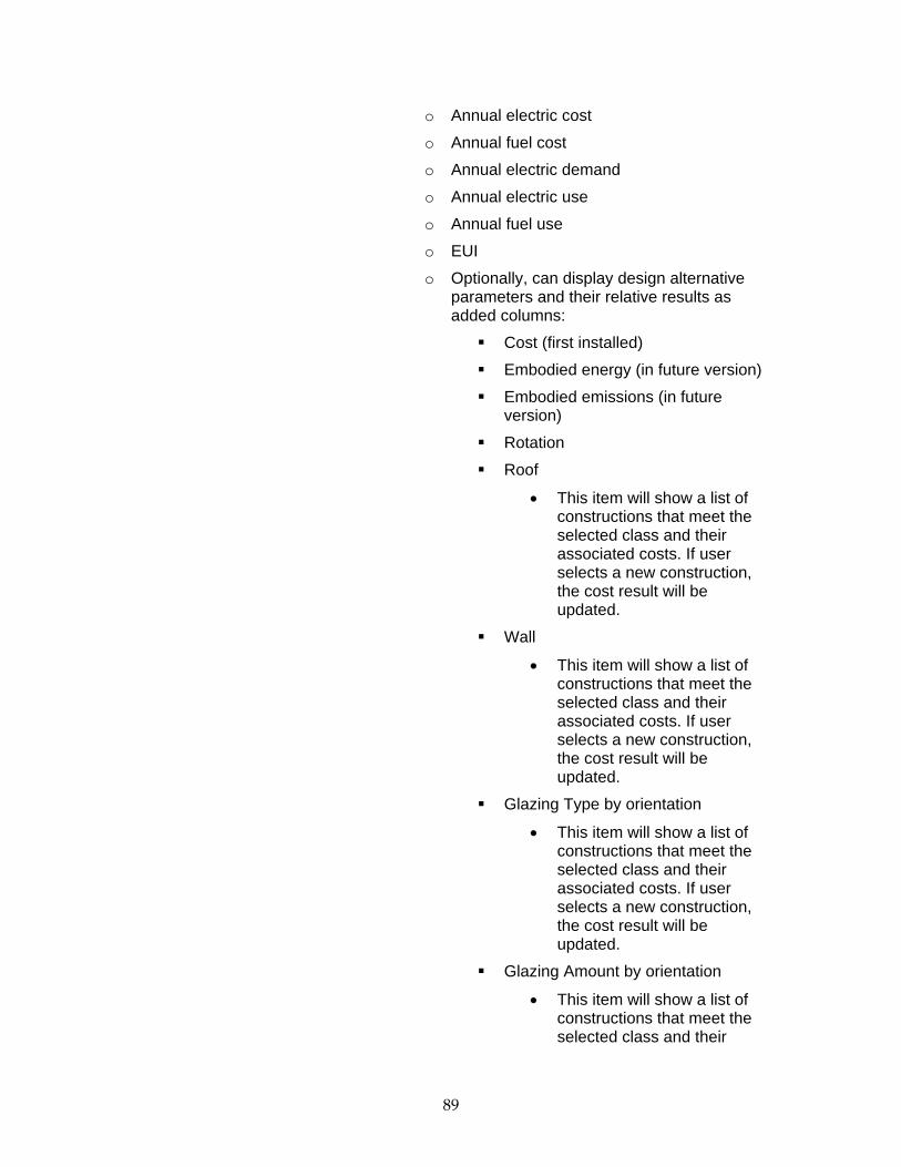
89
o Annual electric cost
o Annual fuel cost
o Annual electric demand
o Annual electric use
o Annual fuel use
o EUI
o Optionally, can display design alternative parameters and their relative results as added columns:
Cost (first installed)
Embodied energy (in future version)
Embodied emissions (in future version)
Rotation
Roof
• This item will show a list of constructions that meet the selected class and their associated costs. If user selects a new construction, the cost result will be updated.
Wall
• This item will show a list of constructions that meet the selected class and their associated costs. If user selects a new construction, the cost result will be updated.
Glazing Type by orientation
• This item will show a list of constructions that meet the selected class and their associated costs. If user selects a new construction, the cost result will be updated.
Glazing Amount by orientation
• This item will show a list of constructions that meet the selected class and their

90
associated costs. If user selects a new construction, the cost result will be updated
Exterior Shading by orientation
• This item will show a list of constructions that meet the selected class and their associated costs. If user selects a new construction, the cost result will be updated
Lighting technology & Controls
• This item will show a list of options that meet the selected class and their associated costs. If user selects a new construction, the cost result will be updated.
HVAC system
• This item will show a list of options that meet the selected class and their associated costs. If user selects a new construction, the cost result will be updated.
Site generation
• This item will show a list of options that meet the selected class and their associated costs. If user selects a new construction, the cost result will be updated.
This page uses the AltRuns table with joins to the AltRunParams table, AltParamValue, AltParamItem, and AltParamType tables, and Runs table.

91
Add Design Alternative Runs Page
Figure 31 Design alternative enabled run list page (example layout)

Design Alternative Parameters below is proposed layout. Roof and wall columns may be organized in tabs to conserve screen space.
Roof Northern Walls
Alt Cost Rotation HVAC Lighting Site Generation
Wall Const.
Interior Mass
Const. Glaze Amt.
Glaze Glaze Amt.
Glaze Shade
Eastern Walls Southern Walls Western Walls
Glaze Amt. Glaze Shade Glaze Amt. Glaze Shade Glaze Amt. Glaze Shade
Proposed screen shot showing tab layout:
This is the ‘Add Alternative’ Page, to add alternatives to a particular base run. The clock icon indicates that the alternative has not been processed yet. Results from previous alternatives for the run are shown as well. Each parameter is selected from the drop down list box in the column heading, and then added when the selection is complete by pressing the Add button at the top left. A group of parameters can be added as well, selected from the ‘Select Group’ drop down box.

The tables below give examples of parameter options. These options will be refined after reviewing RS Means cost data as well as the reasonableness of given options to address the given design implications.
Roof Wall Glazing (for each orientation) Code compliant mass Code compliant mass Code compliant Code compliant steel Code compliant steel Single-pane low-e clear Code compliant wood Code compliant wood Single-pane low-e reflective High insulation mass High insulation mass Single-pane low-e non-HP tint High insulation steel High insulation steel Single-pane low-e HP tint High insulation wood High insulation wood Double-pane low-e clear High albedo mass Double-pane low-e reflective High albedo steel Double-pane low-e non-HP tint High albedo wood Double-pane low-e HP tint High insulation/albedo mass Triple-pane low-e clear High insulation/albedo steel Triple-pane low-e reflective High insulation/albedo wood Triple-pane low-e non-HP tint Triple-pane low-e HP tint
Lighting Technology Lighting Controls HVAC System Class Site Generation Code compliant Code compliant Code compliant Packaged None
LPD 10% less than code Occupancy sensors Hi. Eff. Packaged
Building Integrated Photovoltaics
LPD 20% less than code
Daylighting sensors & controls Best Practice Packaged (> 25 ton)
Nonintegrated Photovoltaics
LPD 30% less than code
Occupancy/Daylighting sensors & controls
Code compliant Water-Cooled Plant
LPD 40% less than code Hi. Eff. Water-Cooled Plant Best Practice Water-Cooled Plant Best Available Technology
Elements The outline below describes the elements on this page from right to left, top down.
• Title: Add Design Alternative Runs
• Table with links:

o Run List
o Run result
o Project
• Link to Design Alternative Groups Page
• Drop down box that selects a design alternative group
o When a group is selected in the drop down box, any existing alternatives in the alternative run list table that have the identical parameters as a group alternative are highlighted in red.
• ‘Add Group’ button which adds the group runs to the alternative run list table
o If an alternative is added which already exists, it is not added. A message in red is shown right above the table stating that it is already present.
Below is a picture of a group that has been selected, which already has alternative runs:
Figure 32 Existing alternatives of the selected group are shown highlighted in red.
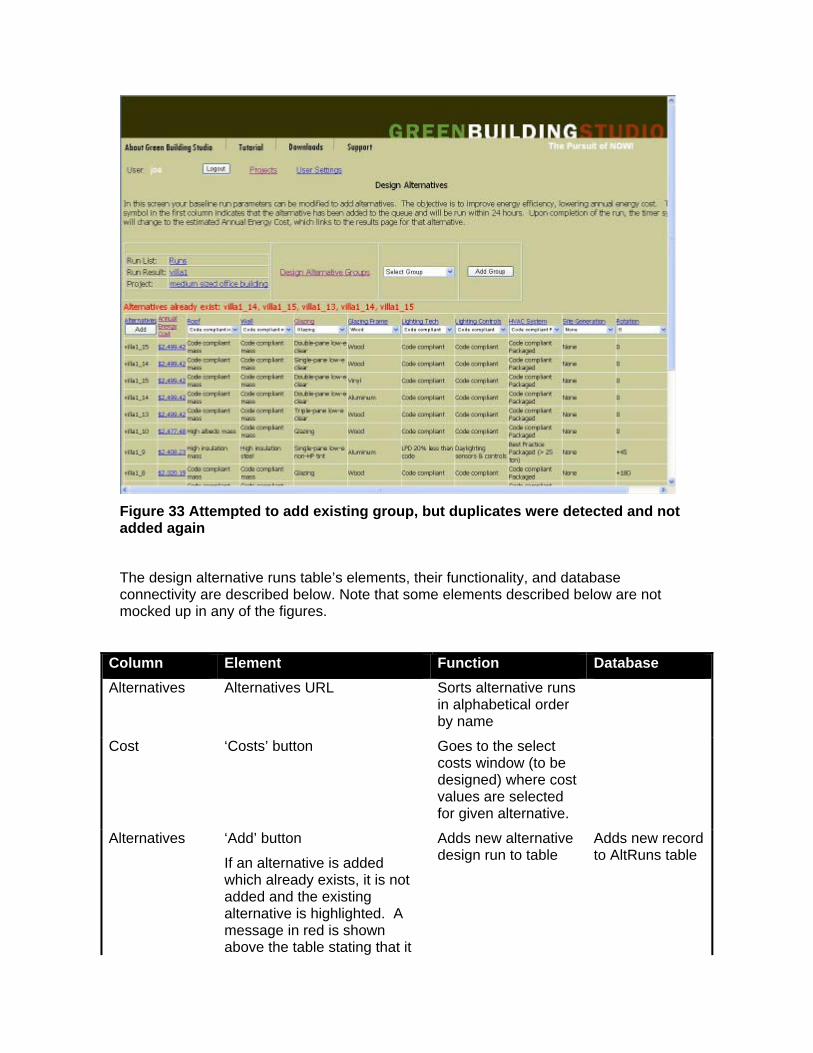
Figure 33 Attempted to add existing group, but duplicates were detected and not added again
The design alternative runs table’s elements, their functionality, and database connectivity are described below. Note that some elements described below are not mocked up in any of the figures.
Column Element Function Database Alternatives Alternatives URL Sorts alternative runs
in alphabetical order by name
Cost ‘Costs’ button Goes to the select costs window (to be designed) where cost values are selected for given alternative.
Alternatives ‘Add’ button
If an alternative is added which already exists, it is not added and the existing alternative is highlighted. A message in red is shown above the table stating that it
Adds new alternative design run to table
Adds new record to AltRuns table
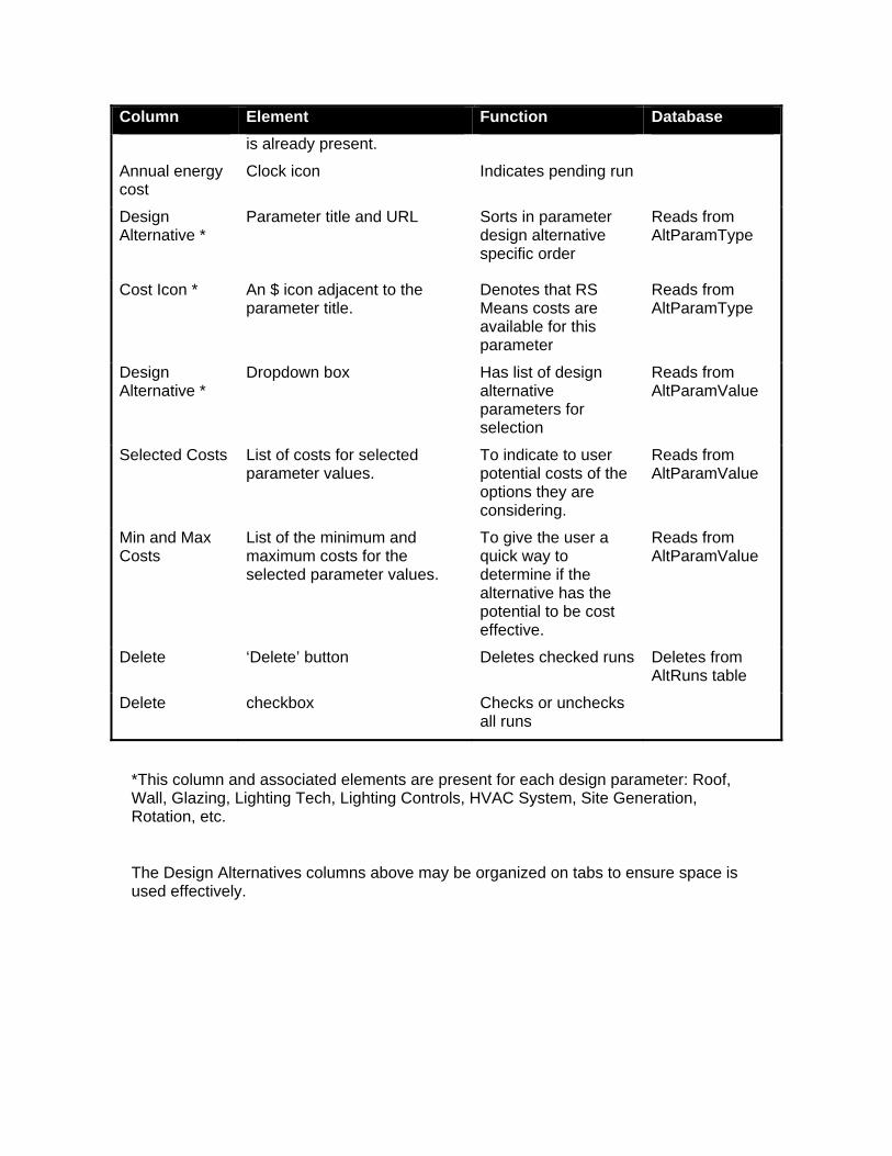
Column Element Function Database is already present.
Annual energy cost
Clock icon Indicates pending run
Design Alternative *
Parameter title and URL Sorts in parameter design alternative specific order
Reads from AltParamType
Cost Icon *
An $ icon adjacent to the parameter title.
Denotes that RS Means costs are available for this parameter
Reads from AltParamType
Design Alternative *
Dropdown box Has list of design alternative parameters for selection
Reads from AltParamValue
Selected Costs List of costs for selected parameter values.
To indicate to user potential costs of the options they are considering.
Reads from AltParamValue
Min and Max Costs
List of the minimum and maximum costs for the selected parameter values.
To give the user a quick way to determine if the alternative has the potential to be cost effective.
Reads from AltParamValue
Delete ‘Delete’ button Deletes checked runs Deletes from AltRuns table
Delete checkbox Checks or unchecks all runs
*This column and associated elements are present for each design parameter: Roof, Wall, Glazing, Lighting Tech, Lighting Controls, HVAC System, Site Generation, Rotation, etc.
The Design Alternatives columns above may be organized on tabs to ensure space is used effectively.

Manage Design Alternative Groups
Figure 34 Manage design alternative groups page
In this screen, the design alternative parameters to be varied are specified and saved as a set of individual alternatives, which can then be applied with one click from the ‘Add Alternatives Page’. This picture shows the screen before a group is specified. Notice that the ‘Add’ button is disabled. Below is a screen shot with a group specified and alternatives added to it.

Figure 35 Manage design alternative groups page with alternative runs added to group. Notice the ‘Add’ button is now enabled These design parameters can now be applied to a baseline run from the ‘Add Design Alternatives’ page, by selecting the ‘Glazing’ group and then pressing the ‘Add Group’ button.
Design Alternative Run Groups entered by a user can be used on any project that user has access to. On projects with multiple users, every user on the project has access to the combined users list of Design Alternative Run Groups.
Links:
• Results page for base run
• Add Alternatives page
Process flow:
1. User selects group from ‘Select group’ dropdown list
2. Default setting is ‘Select group…’
3. If the user does not have any groups, he first needs to:
4. Type desired group name in ‘Add new group’ text entry field

5. Next, press the ‘Submit new Group’ button to add the group to the database
6. It will then be automatically selected in the ‘Select group’ dropdown
7. If the selected group has any existing alternatives, they are displayed.
8. After a group selection is made, the ‘Add’ button in the parameters table is enabled
9. Parameters are then selected from the dropdown columns.
10. When all the desired parameters have been selected, the ‘Add’ button is pressed, and the run is added to the group database and displayed in the first row of the table.
Elements The outline below describes the elements on this page from right to left, top down.
• Title: Manage Design Alternative Groups
• Text input box to add new group
• Button to submit new group, with text ‘Submit New Group’
• Dropdown list to select group
• ‘Delete Group’ button to delete selected group
o A confirmation dialog is displayed
o Upon confirmation, the group and any associated alternatives are removed from the database
• Design parameter table, shown below, very similar to the ‘Add design alternative’ page table. However, design parameters are just being stored in the group, not applied to a run and queued for processing. Later, when this group is applied to a baserun from the ‘Add alternative design run’ page, these alternatives will be applied and run.
Column Element Function Database Alternatives Alternatives URL Sorts alternative
runs in alphabetical order by name
Alternatives ‘Add’ button
If an alternative is added which
Adds new alternative design
Adds to AltGroupParams table

already exists, it is not added and the existing alternative is highlighted. A message in red is shown above the table stating that it is already present
run to table. Button enabled after an alternative group is added or selected.
Design Alternative Parameter*
Parameter URL Sorts in parameter design alternative specific order
Reads from AltParamType
Design Alternative Parameter*
Dropdown box Has list of design alternative parameters for selection
Reads from AltParamValue
Delete ‘Delete’ button Deletes checked runs
Deletes from AltGroupParams table
Delete checkbox Checks or unchecks all runs
*This column and associated elements are present for each design parameter: Roof, Wall, Glazing, Lighting Tech, Lighting Controls, HVAC System, Site Generation, and Rotation. The Design Alternatives columns above will be organized on tabs to ensure space is used effectively.
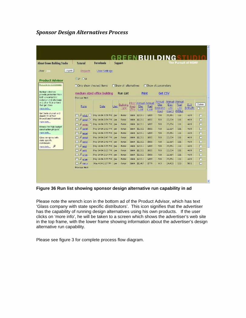
Sponsor Design Alternatives Process
Figure 36 Run list showing sponsor design alternative run capability in ad
Please note the wrench icon in the bottom ad of the Product Advisor, which has text ‘Glass company with state specific distributors’. This icon signifies that the advertiser has the capability of running design alternatives using his own products. If the user clicks on ‘more info’, he will be taken to a screen which shows the advertiser’s web site in the top frame, with the lower frame showing information about the advertiser’s design alternative run capability.
Please see figure 3 for complete process flow diagram.

Sponsor Ad Display
Figure 37 Frameset with Sponsor web site, top, and sponsor alternative run baseline selector, bottom
By selecting a baseline run and pressing the ‘submit’ button, the user will enable the sponsor to run design alternatives using the sponsor’s own product. These runs will then be made available for the user to see, in the project runlist.
Title: Sponsor Ad Display

Elements The outline below describes the elements in the lower frame from right to left, top down.
• Top frame (90%), Sponsor url
o Database: Rules.AdUrl
• Bottom frame (10%) Sponsor message offering design alternative
o Link to select base runs for alternatives.
Database: Runs.ProjectID join on Project.ProjectID

Select base runs for Sponsor Design Alternatives
Figure 38 Run list selection display table This page displays the project runlist for the user to select runs to allow the sponsor to use as base runs for design alternatives. The runlist will show all the runs, including any existing alternatives, so that any run, including existing alternative runs, can be assigned to the sponsor for his alternatives. The sponsor can only see the runs selected by the user.
Elements The outline below describes the elements in the lower frame from right to left, top down.
• Title: Select base runs for sponsor design alternatives
• Project title
• Runlist table, with result columns
o Checkbox at left of each row to select run
• ‘Submit’ button which stores the information and notifies the sponsor. What happens next is outlined below:

1. The sponsor administrator is notified of this request, which has been saved in the GBS database.
2. Using rules based automation; a sponsor employee is assigned the project.
3. Sponsor joins project, and when he logs into GBS the project shows up in his runlist
4. Only the assigned base runs are visible in the project’s run list, to which he then adds his sponsor-specific alternatives and adds to the system queue.
5. The alternative run processor detects these runs in the queue, and processes them
6. The results by default are visible only to the sponsor, in his run list.
7. He reviews the results, and has the option to then make the results visible in the other project member’s runlists, with read-only or read and download (gbXML and DOE file) rights.
8. Once the sponsor makes the results visible to other users, they are identified by an icon to the left of the run title and a tooltip with the sponsor’s name
9. The results are presented using the special style-sheet that has been set up for the sponsor.
10. Please see figure 3 for complete process flow diagram
The elements and functionality are shown below:
Element Function # Characters Validation Database Select Runs checkbox Selects base run for
alternative <50 Alpha numeric,
case sensitive Runs.Title
Date Date of run NA Date -time Runs.DateAdded
User Person who did run <50 Alpha numeric, case sensitive
Runs.UserID
BuildingType Building type <50 Alpha numeric, case sensitive
Project.BuildingTypeID
FloorArea Run floor area NA numeric Runs.FloorArea
Annual Elec Cost Annual elec cost NA currency Runs.AnnualElecCost
Annual Fuel Cost Annual fuel cost NA currency Runs.AnnualFuelCost
Annual Elect Demand Annual Elect demand NA numeric Runs.AnnualElectDemand

Element Function # Characters Validation Database Annual Elect Use Annual Elect Use NA numeric Runs.AnnualElectUse
Annual Fuel Use Annual Fuel Use NA numeric Runs.AnnualFuelUse
EUI EUI NA NA Runs.EUI
Below is the user’s runlist with a few sponsor design alternatives. These are identified by the blue information icon to the left of the run title URL. A tooltip identifies the company.
Figure 39 Sponsor icon associated with sponsor design alternatives

New Project Page
Figure 40 New Project page
This is the new project page, enhanced from the original version. It now has selections for schedule, country, state/province, electric utility, electric utility cost, fuel utility, fuel utility cost and type, and weather location. After entering the location information, the user then presses the ‘Retrieve local weather and utilities’ button. The fields below will then be enabled and the weather design will be displayed.

Elements The table below describes the elements in the page.
Element Function # Characters
Character Rules
DB Field
Project Name Go to project edit page for selected project.
<50 Alpha numeric, case sensitive
Project.Title
Building Type Dropdown box with building types
NA NA Project.BuildingTypeID
Schedule Dropdown box with occupancy schedules
NA NA Project.ScheduleID
Project Type Radio button selector for actual or demo project
NA NA Project.DemoID
Country Dropdown box with countries. Default is US and only zip code box is enabled. If Non-US the zip code box is disabled and State, City are enabled. When user enters zip or selects city,
NA NA Project.CountryID
State/ Province State/Province Text entry field. Enabled when non US country is selected.
<50 Alpha numeric, case sensitive
Project.State
City City Text entry field. Enabled when non US country is selected
<50 Alpha numeric, case sensitive
Project.City
Zip Code Zip code text entry field. Enabled when US is the country
5 numerical Project.Zipcode
Button Retrieves local weather and utilities based on the location information
NA NA NA

Element Function # Characters
Character Rules
DB Field
Electric Utility Dropdown box with electric utilities. Utilities lists are built with local utilities and associated costs shown.
NA NA Project.EUtilityID
E.U. Cost Displays value after electric utility is selected. Can be edited.
NA float Project.EUCost
Fuel Utility Dropdown box with fuel utilities. Utilities lists are built with local utilities and associated costs shown.
NA NA Project.FuelUtilityID
Fuel Type Dropdown box NA NA Project.FuelTypeID
Fuel Cost Displays value after gas utility is selected. Can be edited.
NA float Project.FuelCost
Fuel Units Dropdown box NA NA Project.FuelUnitID
Weather Location Dropdown box with weather datafile name for specific location. If more than one, user must choose. The distance from the main city may be in shown in name
NA NA Project.WeatherID
Weather design This is a display field echoing the weather location
NA NA NA

Display runs relative to baseline This is an alternative method of displaying results on the Run List page. Instead of absolute values, one run would be selected as the baseline and the other runs would be displayed with their result values relative to the base. The table below illustrates, with some sample columns.
Run Title Fuel Cost Electrical Cost Run1 -$1400 -$1900
AltRun1 -$1300 -$1500
AltRun2 -$800 -$1100
Peta3 0 0
AltRun2_1 +$200 +$300
Figure 41 Run List with Design Alternatives
In the table above run Peta3 is the baseline. The run to use as a baseline is selected by

clicking on the bullseye icon. Clicking on the same icon again will deselect it. Clicking on another icon will select it.

Sponsor Ad Setup – page 1 Below is the page used to setup an ad and enable the alternative design run capability.
Figure 42 Sponsor Ad setup page with design alternative request option. Title: Sponsor Ad Setup (page 1)
In this page, the associate enters the ad copy, URL, and rules for display. He also has the option of specifying that design alternative assistance is available.
Sponsor Ad Setup page elements and functionality is shown in the table below:
Element Function # Characters Validation Database Ad copy text entry field Associate enters ad
copy <250 Alpha numeric,
case sensitive Rules.AdCopy
Ad url text entry field Associate enters ad url
<100 Alpha numeric, case sensitive
Rules.AdUrl

Element Function # Characters Validation Database Design alt checkbox Indicates availability of
design alternative assistance
NA NA Rules.bAltRuns
Select category dropdown listbox
Selects a category of display rules
NA NA Criteria_LKUP
Select rule dropdown box Selects specific rule after category has been selected
NA NA Criteria_LKUP
Operator dropdown box Selects operation to apply, eg ‘=’, ‘.’, etc.
NA NA Operator_LKUP
Value field dropdown box Lists values from selected lookup table
NA NA varies
Value1 text entry field Value for rule, or first value if range
<10 Numeric NA
Value2 text entry field Second value of range <10 Numeric NA
Add button Adds rule to list in rule listbox
NA NA NA
Remove button Removes rule from list in listbox
NA NA NA
Rule Listbox Lists all the display rules for the ad
NA NA Rules.RuleText
Cancel Button Cancels ad if new ad, or changes if editing ad
NA NA NA
Next button Navigates to next page in ad entry process
NA NA NAS

Sponsor Ad Setup page 2
Figure 43 Sponsor Ad Setup page 2 - additional sponsor ad parameters Title: Sponsor Ad Setup (page 2) This is the next page in the ad entry/edit process, which is used to specify the CSI categories and Green certification.
Sponsor Ad Setup page 2 elements and functionality are shown in the table below:
Element Function # Characters Validation Database CSI category dropdown listbox
Selects CSI category
NA NA CSI_Division_LKUP
CSI subdivision dropdown listbox
Selects CSI subdivision
NA NA CSI_SubDivision_LKUP
Add button Adds CSI subdivision to dropdown CSI list below
NA NA NA

Element Function # Characters Validation Database Remove button Removes CSI
subdivision from dropdown CSI list below
NA NA NA
CSI listbox Lists the selected CSI subdivisions
NA NA Rules.CSI
Certified Green Product checkbox
If checked, will save Green Certification entered below it
NA NA NA
Green Certification text entry field
Shows Green Certifications
NA NA Rules.GreenCriteria

Sponsor Rep List Below is the Sponsor Rep List page.
Figure 44 Sponsor Rep List page (sample) Title: Sponsor Rep List This page is used by the sponsor to email invitations to his reps to join Green Building Studio, under his aegis. These studio members will then have the ability to do design alternatives for selected base runs, in response to user requests to the associate’s company ads.
Element Function # Characters Validation Database Rep email entry textbox
Selects CSI category <50 Alpha numeric, case sensitive
SponsorMember.Email
Submit button Submits email address to database, sends out email invitation
NA NA NA
Remove button (not shown above)
Removes checked rep from sponsor relationship
NA NA NA
Remove Checkbox (not shown above)
When checked and remove button clicked rep removed from sponsor. Any accounts assigned to
NA NA NA

Element Function # Characters Validation Database the rep will be reassigned via the Sponsor Rep Assignment page, shown below.
Email table column Shows email addresses of reps, in date order, most recent first
NA NA SponsorMember.Email
Status column Shows whether or not user has registered for GBS
NA NA SponsorMember.Pending
Date Invited column Shows the date and time invitation was emailed
NA NA SponsorMember.DateAdded

Sponsor Rep Assignment Below is the alternative design requests and assignments page:
Figure 45 Sponsor Rep assignment page Title: Sponsor Rep Assignment
This is a table of projects with alternative design requests for the associate. The Project title, building type, design phase, and request date are shown. The ‘Select’ column is used to assign the alternative design request to one of the associate’s reps, which are listed in the ‘Assigned to:’ dropdown box. Here is the process:
1. Green building studio user clicks on a sponsor ad and then clicks on the design alternative base run selection page.
2. The request will show up in this table, which the associate will see next time he logs in to the Associate site.
3. The associate will assign the alternative run to one of his reps, selected from the drop down listbox.
4. The rep will get an email invitation to join the project.
5. When the rep accepts the invitation and logs into Green Building Studio, he will see only the designated base runs in the project run list.
6. The rep will run design alternatives of his choosing, which demonstrate his product.

7. The rep will review the results and choose which design alternative results to make visible. These can be with read-only permissions, or read and download permissions.
8. The user can delete any of the results that are visible to him, at his option.
The elements and functionality are shown below:
Element Function # Characters Validation Database Project Project title <50 Alpha numeric,
case sensitive Project.Title
BuildingType Project building type NA NA Project.BuildingTypeID
Budget Project budget NA NA Project.BudgetID
Phase Project design phase NA NA Project.PhaseID
Date Added Project create date NA NA Project.DateAdded
DB Action column Select, update or cancel
NA NA Performs selected action
Assigned to: Selects rep to assign project to
NA NA tbd


Appendix C - GBS Software Development Kit Documentation


The Green Building Studio Web Service
Energy Analysis Module
Software Developers Kit
EAM Version 2.0
SDK Rev. 2.01
Green Building Studio, Inc. Copyright 2006 Green Building Studio, Inc.


Table of Contents
1.1. Background and Overview ..................................................................................................... 7 1.2. Project Objectives ...................................................................................................................... 8
1.3. Report Organization ................................................................................................ 8
2.1. Requirements ........................................................................................................... 9 2.1.1. Key Update Requirements ..................................................................................................... 9 2.1.2. GBS Web Service Requirements .......................................................................................... 10 2.1.3. gbXML Plug-in Requirements ............................................................................................. 11
2.2. Specifications .......................................................................................................... 12
Add Design Alternative Runs Page ................................................................................... 13 2.2.1. Elements ............................................................................................................................ 17 2.3. Test Plan Development ............................................................................................................. 18
2.3.1. Software Development (Tasks 3) ....................................................................... 18
2.3.2. Beta Testing (Task 4) ............................................................................................. 19
2.3.3. Identify Alternative Business Strategies (Task 5) .......................................... 21
2.3.4. Regional, National, and global Match Activities (Task 6) ............................ 22
3.1. Objective 1. Build upon past work to enhance the GBS to ensure it can assist architects in cost effectively achieving the LEED goals as outlined in California’s Executive Order S-20-04 .............................................................................. 23
3.1.1 Green Building Studio Design Alternatives ......................................................................... 23
3.2. Objective 2. Continue to partner with CAD vendors to further integrate this functionality into their current CAD tools .............................................................. 25
3.2.1. gbXML Plug-ins ................................................................................................................... 25 3.2.4. CAD Vendor gbXML Efforts ............................................................................................... 33
3.3. Objective 3. Continue to partner with a California utility to develop and conduct training program for architects to accelerate the use of the GBS in their practice .................................................................................................................................... 38
3.4 Objective 4. Implement a business plan that begins generating revenue from the GBS that is projected to sustain the GBS web service ............................. 39
3.5 Objective 5. Continue to encourage the development of gbXML as a non-proprietary standard for exchanging high-level design information between CAD tools and energy analysis tools ........................................................................................ 41
4.1. Major Conclusions ................................................................................................. 43
4.2. Commercialization Potential ............................................................................... 44
4.3. Benefits to California ............................................................................................. 44
4.4. Recommendations ................................................................................................. 45 Introduction ...................................................................................................................... 62
Program Requirements .................................................................................................... 62
Functional Requirements ........................................................................................................ 62 User Interface ...................................................................................................................................... 62 User Experience ................................................................................................................................... 62 Session Time Out ................................................................................................................................. 62
Platform Requirements ........................................................................................................... 62 Server Platform .................................................................................................................................... 62 Client Platform .................................................................................................................................... 63
Program Objectives .......................................................................................................... 64
Current Solution ...................................................................................................................... 64
Design Alternative Enhancement ........................................................................................... 65
Additional GBS Enhancements .............................................................................................. 65 Program Overview............................................................................................................ 67
Basic Design ............................................................................................................................. 67
Program Flow Diagrams ......................................................................................................... 68
Basic Program flow ................................................................................................................. 69
User Design Alternative Web Page Flow ............................................................................... 70
Sponsor Run Page Flow .......................................................................................................... 71
Add Sponsor Product Parameters ......................................................................................... 73
Windows Service and process flow ........................................................................................ 74
Database ................................................................................................................................... 76 Web Pages ........................................................................................................................ 84
Site GUI Requirements ........................................................................................................... 84 Font ...................................................................................................................................................... 84 Format Style ........................................................................................................................................ 84 Navigation ........................................................................................................................................... 85
Run List Page ........................................................................................................................... 86
Add Design Alternative Runs Page ........................................................................................ 91
Manage Design Alternative Groups ....................................................................................... 97
The Design Alternatives columns above will be organized on tabs to ensure space is used effectively.Sponsor Design Alternatives Process ................................................................. 100
Sponsor Design Alternatives Process ................................................................................... 101
Sponsor Ad Display ............................................................................................................... 102
Select base runs for Sponsor Design Alternatives .............................................................. 104
New Project Page ................................................................................................................... 107
Display runs relative to baseline .......................................................................................... 110
Sponsor Ad Setup – page 1 .................................................................................................. 112
Sponsor Ad Setup - page 2 .................................................................................................... 114

Sponsor Rep List ................................................................................................................... 116
Sponsor Rep Assignment ...................................................................................................... 118 Conventions Used in This Document ............................................................................ 129
Format Styles ......................................................................................................................................129 Data Types ..........................................................................................................................................129
Introduction .................................................................................................................... 130
What is the Energy Analysis Module? ................................................................................. 130 Development Requirements ........................................................................................... 131
Operating Systems ................................................................................................................. 131
3D-CAD Application Requirements .................................................................................... 131
Developer Tools ..................................................................................................................... 131 XML Editor ........................................................................................................................................131 VRML browser plug-in ......................................................................................................................131
Basic Program Flow .............................................................................................................. 133 Energy Analysis Module API ........................................................................................ 134
Overview ................................................................................................................................. 134
EAM Functionality ................................................................................................................ 134 User Login ..........................................................................................................................................134 List User’s Projects .............................................................................................................................134 List User’s Project Runs .....................................................................................................................134 Request Energy Results for a New Run ..............................................................................................134 Request Energy Results for an Existing Run ......................................................................................135
Functions ................................................................................................................................ 139 Initialize .........................................................................................................................................139 ListProjects ..................................................................................................................................139 ListRuns .........................................................................................................................................139 NewRun ..........................................................................................................................................140 GetResults ....................................................................................................................................141
XML Schema Support .................................................................................................... 142
Minimum Element Support .................................................................................................. 142 <gbXML> ...........................................................................................................................................142 <Campus> .........................................................................................................................................143 <Building> ....................................................................................................................................145 <Space> ...........................................................................................................................................146 <Surface> .......................................................................................................................................152 <Opening> .......................................................................................................................................155 <PlanarGeometry> ..............................................................................................................................157 <PolyLoop> ........................................................................................................................................158 <CartesianPoint> ................................................................................................................................158 <Coordinate> ......................................................................................................................................158 <RectangularGeometry> .....................................................................................................................158 <Results> ............................................................................................................................................159
EAM Object Rules .......................................................................................................... 162
Space ....................................................................................................................................... 162

Surface .................................................................................................................................... 162 Thermal Model Development ........................................................................................ 162
Overview ................................................................................................................................. 162
The Process ............................................................................................................................ 162 Take Offs ............................................................................................................................................162 Define Building Envelope and Constructions .....................................................................................163 Define Building Systems and Operation .............................................................................................165 Iterative De-bugging, Syntax and Error Checking ..............................................................................166
EAM Limits .................................................................................................................... 166
DOE-2 Limits .....................................................................................................................................166
Beta Test Report for .............................................................................................................. 171
Conceptual Design Energy Analysis Tool Phase III ........................................................... 171
Contract #: 500-04-020 .......................................................................................................... 171
January, 2007 ......................................................................................................................... 171 Contractor Project Manager: John Kennedy .......................................................................................171 Commission Project Manager: Norm Bourassa ..................................................................................171
Introduction .................................................................................................................... 171
Testing Methodology ...................................................................................................... 171
Components tested. ............................................................................................................... 172
Tests Conducted .................................................................................................................... 172 Testing and Results ........................................................................................................ 173
Testing of Web Site ................................................................................................................ 173
Test Case Number: 5.2 .......................................................................................................... 173
New User Registration Page ................................................................................................. 173
Load Testing of Web Service ................................................................................................ 177
Simulation Testing ................................................................................................................. 177
Beta Testing ............................................................................................................................ 179
Current Outstanding Issues .................................................................................................. 180 Green Building Studio web site and service .......................................................................................180 Graphisoft ArchiCAD gbXML plug-in ..............................................................................................182 Autodesk Architectural Desktop gbXML plug-in ..............................................................................182

Conventions Used in This Document
Format Styles This document uses various conventions to present information. Words that require special treatment appear in specific fonts or font styles.
EAM Property – EAM property names are shown in Arial Black italic font.
EAM Function – EAM functions are shown in Arial Black font.
XML Element – XML element names are shown in Courier New font.
XML Attribute – XML attribute names are shown in Courier New italic font.
Speed Tips – Speed tips are shown in Arial Narrow font. Speed tips are given throughout the SDK as recommendations to the CAD developer to increase the speed of the EAM by going beyond the minimum requirements. The icon to the right indicates these are located in the adjacent paragraph.
Data Types The data types Integer, String, and Boolean are used by the EAM and are defined by the World Wide Web Consortium (www.w3c.org).

Introduction What is the Energy Analysis Module? Green Building Studio, Inc.s’ Energy Analysis Module (EAM) is a server application that enables any 3D-CAD application that supports the Green Building XML schema (gbXML) the ability to access DOE-2.2 as well as EnergyPlus. This powerful server application is enabled through Green Building Studio, Inc.s’ Green Building Studio (GBS) web service.
In the past sophisticated building energy simulations required a highly skilled and expensive individual to build a text based computer model of a building that contained all types of information that only an energy expert would know. This has always been the market barrier for 3D-CAD tools developers to develop such solutions. The large investment required to enable their applications to collect all the information necessary to conduct a simulation was too difficult, if not impossible, to justify to their product managers. The EAM changes all this. The EAM only requires the location of the building, the type of building, and the geometry of its major components. That is it! The EAM uses this information to expand this simplified dataset to that needed for energy simulation using defaults based on the building practices and codes in a specific region of the world.
This manual will assist you in enhancing your application so it can use the EAM and enable your user base to have access to sophisticated building analysis engines with no required knowledge of such engines.

Development Requirements Operating Systems Version 2.0 of the Energy Analysis Module runs on 32-bit windows operating systems running on x86 processors and is specifically targeted to run on Windows 2003 servers using the .NET Framework.
The EAM runs on Green Building Studio, Inc.s’ web servers and is only accessible using the Simple Object Access Protocol (SOAP) over the Internet.
3DCAD Application Requirements A 3D-CAD application as well as the developed client that will interact with the EAM through the Green Building Studio must have the following capabilities and requirements.
• Ability to relate surfaces to spaces.
• Ability to distinguish between surface types, ie. floor, ceiling, exterior wall, interior wall, roof, etc..
• Ability to clip surfaces based on connection to spaces.
• Ability to store User’s username and password on the client computer.
• Ability to save the GBS ProjectID with the 3D-CAD model it is associated with.
• Ability to create, read, edit and write XML documents.
• Ability to open a URL in a browser application.
• Ability to compress a gbXML file using zip compression and encode this file using base64 encoding.
• Ability to make SOAP calls including through a proxy server.
• Ability to save the gbXML file locally on the client computer.
• Ability to define a unique name for the submitted run.
Developer Tools Several advanced technologies are used by the EAM and because of this you will require some tools to work with these technologies.
XML Editor One of the basic requirements of any 3D-CAD tool supporting the EAM is that it can read and write XML files. Using an XML editor to view and edit these files is essential. We have had success with XML Spy in its consistency with the various XML schema standards.
VRML browser plug-in Once you start writing a model’s geometry to an XML file in the gbXML schema format you will need a VRML viewer to help in visually validating your geometry to ensure it is being exported

as expected. We recommend the Parallel Graphics Cortona VRML client viewer (www.parallelgraphics.com).
As part of the Green Building Studio, Inc.s’ SDK web site there is a link to a VRML stylesheet that is used to convert a gbXML file to VRML. The .NET GBS Client is also distributed with this stylesheet.

Basic Program Flow The diagram in Figure 46illustrates the concept behind the EAM. In essence, a 3D-CAD model can be highly complex and have detail that is not relevant to an energy analysis simulation. For this reason the 3D-CAD tool will need to extract a subset of this data for the EAM.
3D-CAD Application
Highly Complex 3D-CADBuilding Model
BuildMono-Planar
Model & Exportusing gbXML
elements.
Read in resultsfrom gbXML file
or use EAMResults window.
File containing gbXMLelements generated by3D-CAD tool and theEAM. (one for eachanalysis request)
Energy Analysis Module
Mono-Planarmodel enhanced
with intelligentEAM defaults forenergy analysis.
Energy analysisresults exported
to gbXML.
Figure 46- Simplified Program Flow
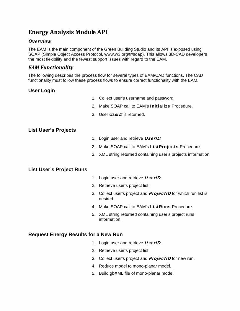
Energy Analysis Module API Overview The EAM is the main component of the Green Building Studio and its API is exposed using SOAP (Simple Object Access Protocol, www.w3.org/tr/soap). This allows 3D-CAD developers the most flexibility and the fewest support issues with regard to the EAM.
EAM Functionality The following describes the process flow for several types of EAM/CAD functions. The CAD functionality must follow these process flows to ensure correct functionality with the EAM.
User Login 1. Collect user’s username and password.
2. Make SOAP call to EAM’s Initialize Procedure.
3. User UserD is returned.
List User’s Projects 1. Login user and retrieve UserID.
2. Make SOAP call to EAM’s ListProjects Procedure.
3. XML string returned containing user’s projects information.
List User’s Project Runs 1. Login user and retrieve UserID.
2. Retrieve user’s project list.
3. Collect user’s project and ProjectID for which run list is desired.
4. Make SOAP call to EAM’s ListRuns Procedure.
5. XML string returned containing user’s project runs information.
Request Energy Results for a New Run 1. Login user and retrieve UserID.
2. Retrieve user’s project list.
3. Collect user’s project and ProjectID for new run.
4. Reduce model to mono-planar model.
5. Build gbXML file of mono-planar model.

6. Save this gbXML file on client’s hard drive.
7. Compress the gbXML file with zip compatible compression and encode with base64 encoding.
8. Make SOAP call to the EAM’s GetNewResults Procedure.
9. Depending on GetNewResults arguments a URL is returned for the results web page or the zipped gbXML file.
Request Energy Results for an Existing Run 1. Login user and retrieve UserID.
2. Retrieve user’s project list.
3. Collect user’s project and ProjectID.
4. Retrieve user’s project run list.
5. Collect user’s run and RunID.
6. Make SOAP call to EAM’s GetResults Procedure.
7. Depending on GetResults arguments a URL is returned for the results web page or the zipped gbXML file.

Visual Basic Example Below is a simple example of how to request energy results from the EAM.
Types of Results The EAM will populate the gbXML file with the results of the simulation. The results fall into four categories; energy use and costs, thermal loads, space/zone air-flow requirements, equipment sizes and constructions. These results and their mappings are listed in the table below.
Energy Use & Costs Energy uses include the rate of energy use (power) for electricity and fuel.
Result Mapped to…
Annual Electricity Peak Demand
Campus & Building
Annual Electricity Use
Campus & Building
Monthly Electricity Use
Campus & Building
Function EnergyResults(UserID as Integer, strGBXML as String _ Username as String, Password as String, ProjectID as Integer) as String Dim SOAPWSDL as String, soapclient As SoapClient, SimID as Long Dim strMSG as String, strURL as String, strVersion as String SOAPWSDL = "http://www.greenbuildingstudio.com/soap/eam.wsdl" SET soapclient = New SoapClient soapclient.mssoapinit SOAPWSDL strMSG = soapclient.Initialize(UserID, Username, Password, strVersion) If strMSG = “” Then strMSG = soapclient.NewRun(UserID, vbTrue, strGBXML, strURL) If strMSG = “” then EnergyResults = strURL Else EnergyResults = strMSG End If Set soapclient = Nothing Else

Result Mapped to…
Annual Fuel Use Campus & Building
Monthly Fuel Use Campus & Building
Annual Electricity Cost
Campus & Building
Annual Fuel Cost Campus & Building
Thermal Loads Thermal loads are determined for each component in a building that can transmit or produce a load and will be included in the results.
Result Mapped to…
Monthly Heating Loads Components
Building & Spaces
Monthly Cooling Loads Components
Building & Spaces
Monthly Peak Heating Load Components
Building & Spaces
Monthly Peak Cooling Load Components
Building & Spaces
Equipment and Construction Information The simulation engine, DOE-2, the EAM uses does size various pieces of equipment based on the design conditions the EAM uses for the location of the building. The defaults for system and plant equipment will also be in the resulting gbXML file. The constuction information will include all opaque and transparent construction material data including properties and quantities.
Result Mapped to…
System Types Building
Cooling Capacity Air Loop, Hydronic Loop
Heating Capacity Air Loop, Hydronic Loop
Fan CFM Air Loop, Zone
Fan Static Pressure Air Loop
Envelope Construction Building

Summary
Comfort Information The simulation engine, EnergyPlus, can also determine the temperatures in the building’s spaces. The information below is also available in the results. Future simulation engines will be able to provide humidity information as well to determine comfort values for a space.
Result Mapped to…
Monthly Maximum Temperature
Spaces
Monthly Minimum Temperature
Spaces
Monthly Ave. Temperature Spaces

Functions
Initialize This is the first function called by the 3D-CAD application. It validates the user’s username and password, then retrieves the identifier for this user.
Syntax Initialize(Username as String, Password as String) as String
Argument In/Out Description
Username Input Username for user.
Password Input Password for user.
Returns the UserID as a string if successful.
Returns error message as a string if unsuccessful.
ListProjects This function returns a list of projects that are associated with the company license.
Syntax ListProjects(UserID as Integer) as String
Argument In/Out
Description
UserID Input Unique Identifier for this user returned from Initialize function.
Returns an XML string containing project information described below. If unsuccessful the URL will be to an error page describing the problem.
Example Projects XML string.
<?xml version='1.0'?> <EAM> <Project id='12' date=’2003-07-12T14:04:00’ rights='Owner' title=’Test Project’ /> <Project id='14' date=’2003-07-12T14:04:00’ rights='Owner' title=’Cotati School Gym’ /> <Project id='13' date=’2003-07-12T14:04:00’ rights='Read-only' title=’GBS Office’ /> <Project id='16' date=’2003-07-12T14:04:00’ rights='Iterate' title=’Sonoma Hospital’ /> </EAM>
ListRuns This function returns a list of runs associated with a project license. This function currently does

not return a list of Design Alternative runs.
Syntax ListRuns(UserID as Integer, ProjectID as Integer) as String
Argument In/Out
Description
UserID Input Unique Identifier for this user returned from Initialize function.
ProjectID Input ProjectID for project which runs are requested.
Returns an XML string containing run information described below. If unsuccessful the URL will be to an error page describing the problem.
Example Runs XML string. <?xml version='1.0'?> <EAM> <Run id='12' title=’Run #1’ dateadded=’2003-07-12T12:24:00’ user='John Kennedy' status=’Queued’/> <Run id='14' title=’Run #2’ dateadded=’2003-07-12T14:04:00’ user='John Kennedy' status=’Analysis Completed’/> <Run id='15' title=’Run #3’ dateadded=’2003-07-12T14:33:00’ user='John Kennedy' status=’Analysis Started’/> </EAM>
NewRun This function begins a series of events that eventually leads to the results form being displayed, if desired, with the selected scenario's results displayed.
Syntax NewRun(UserID as Integer, Title as String, ProjectID as Integer, zegbXML as String) as String
Argument In/Out Description
UserID Input Unique Identifier for this user returned from Initialize function.
Title Input Title for this new run that user can specify. (Maximum character length is 50)
ProjectID Input ProjectID for project which new run is for.
zegbXML Input A string containing the base64 encoded and zip compressed gbXML data

Argument In/Out Description
from the CAD application for the EAM.
Function returns a URL preceeded with “http://” for the status page or message text if problems occurred.
GetResults This returns either a URL preceded with “http://” for the requested result type or a message to indicate any errors or status on retrieving the requested result.
Syntax GetResult(UserID as Integer, RunID as Integer, ResultType as Integer) as String
Argument In/Out Description
UserID Input Unique Identifier for this user returned from Initialize function.
RunID Input Id of the Run whose results are requested.
ResultType Input An integer value indicating on what is desired to be returned by the command.
0=URL to Results Web Page
1=URL to zip compressed gbXML file
2=URL to VRML file created from gbXML file.
3=URL to DOE-2.2 file created from gbXML file.
10=Base64 encoded string of the zipped post-GBS gbXML file.
1.1.

XML Schema Support The EAM utilized gbXML for transferring data to and from a CAD application. The gbXML schema is very large and complex, and the three sections below discuss the different level of support the EAM has for the schema. The first lists the minimum elements required by the EAM with optional elements and attributes listed that add some benefits to the EAM but aren’t essential. THE SCHEMA SHOULD ALWAYS TAKE PRECEDANCE OVER THIS DOCUMENTATION FOR MINIMUM REQUIREMENTS. The second section describes the truly optional elements in the schema that the EAM supports, but a CAD developer may choose not to support them based on the user’s needs. Finally, the third section describes the elements that the EAM does not support at this time.
Under each element heading is a image illustrating the element and its children elements.
Minimum Element Support The EAM only requires that a small element subset of the gbXML schema be supported. These elements are listed below with explanations of what they are. Sometimes the minimum EAM required elements or attributes conflict with those specified as required by the schema. This is because the EAM has unique requirements to simplify data input necessary for energy analyses. To develop an XML file that will work with the EAM this section overrules the schema’s minimum required elements.
<gbXML> The gbXML element is required as are the following attributes contained in the gbXML element.
Minimum • Id – attribute with unique identifier for this gbXML
element. This identifier must be unique for the entire XML file.
• temperatureUnit – TemperatureUnit type attribute defining the default units for temperature in this file.
• lengthUnit – LengthUnit type attribute identifying the default unit for length used in this file.
• areaUnit – AreaUnit type attribute identifying the default unit for area used in this file.
• volumeUnit – VolumeUnit type attribute identifying the default unit for volume used in this file.
• SIResults – Boolean type attribute identifying what units class the results will be in. True is for International System of Units (SI) and False is for Imperial Units (IP).
• Campus – the Campus element is described in the next section and is required.

Optional • CreatorCADInfo – element containing information about
the CAD tool used to generate this gbXML file.
o CompanyName – element containing the CAD tool developer’s company name.
o ProductName– element containing product name of the CAD tool.
o Version – element containing the version of the CAD tool.
o Platform – element containing the platform the CAD tool is running on.
• CreatorPersonInfo – element containing information about the creator of this gbXML file.
o FirstName – element containing the first name of the file creator.
o LastName– element containing the last name of the file creator.
o MiddleName – element containing the middle name of the file creator.
o Email1Address – element containing the email address of the file creator.
o WebPage– element containing the web page URL of the file creator’s company.
o CompanyName – element containing the company name of the file creator.
<Campus> The Campus element is required. There can only be one Campus element in the gbXML file.
Minimum • Location – element identifying campus location with the
following elements and attributes defined
o Name – element with location name.
o ZipcodeOrPostalCode – element containing the zipcode or postal code for campus location.
Optional
o Description – element with description of campus location.

o Longitude – element containing the longitudinal coordinate of campus origin location in decimal degrees.
o Latitude – element containing the latitudinal coordinate of campus origin location in decimal degrees.
o Elevation – element containing the elevation of the campus origin point.
• Building – the building element is described in the next section.
• Surface – the Surface element is described in a later section. This element is required to define any surface in or on a building including shading surfaces that shade a building.
Optional • Id – attribute with a unique identifier for this campus
element. This identifier must be unique for the entire XML file.
• DesignHeatWeathIdRef – attribute for specifying the heating design data element identifier used for load calculations and sizing equipment.
• DesignCoolWeathIdRef – attribute for specifying the heating design data element identifier used for load calculations and sizing equipment.
• YearModeled – By default the current year is the year used in all analyses. If a year is exported with the XML file it will be used instead.
• MeterId – Specifies the energy meter element identifiers assigned to this campus.
• ExtEquipId – Specifies the external equipment element identifiers assigned to this campus.
• LightId - Specifies the lighting element identifiers assigned to this campus.
• LightControlId – Specifies the lighting control element for the assigned lightId.
o LightId – Identifier for the light element controlled by this lighting control.
o ScheduleIdRef – Identifier for the schedule that defines how this light operates.

<Building>
The Building element is required. There can be more than one Building element in a gbXML file.
Minimum • Id – Attribute with a unique identifier for this building
element. This identifier must be unique for the entire XML file.
• BuildingType – Enumerated Attribute identifying the type of building.
Table 2 - Building Type enumerations BuildingType Description
AutomotiveFacility
ConventionCenter
Courthouse
DiningBarLoungeOrLeisure
DiningFamily
Dormitory
ExerciseCenter
FireStation
Gymnasium
HospitalOrHealthcare
Hotel
Library
Manufacturing
Motel
MotionPictureTheatre
MultiFamily
Museum
Office
ParkingGarage
Penitentiary
PerformingArtsTheater
PoliceStation

BuildingType Description
PostOffice
ReligiousBuilding
Retail
SchoolOrUniversity
SingleFamily
SportsArena
TownHall
Transportation
Warehouse
Workshop
• Area – Total floor area of building. The sum of all floor areas contained in space elements whose height is over five feet or is occupied.
Optional
o unit – areaUnit type attribute specifying units of building area. Required if different from areaUnit default.
• Space – The Space element is described in the next section.
Optional • Name – Element with name of building.
• Description – Element containing description of this building.
<Space> The Space element is required. There can be many Space elements in a gbXML file. A space represents a volume enclosed by various surfaces types. It can exist above grade, below grade, or both.
Minimum • Id – Attribute with a unique identifier for this space
element. This identifier must be unique for the entire XML file.
• Area – Total floor area of this space as measure by the sum of areas for each Surface element of type InteriorFloor, UndergroundSlab, RaisedFloor, or SlabOnGrade contained in the space.

Optional
o unit – areaUnit type attribute specifying units of space area. Required if different from areaUnit default.
• CADObjectId – Element containing the CAD application's unique identifier for this space.
Optional • Name – Element with name of space.
• Volume – Element containing the volume of this space as defined by the volume enclosed by all the surfaces adjacent to this space. TIP - specifying this element will speed the analysis portion of the EAM because the EAM will no longer have to determine this value.
Optional
o unit – volumeUnit type attribute specifying units of space volume. Required if different from volumeUnit default.
• conditionType – Enumerated attribute identifying the type of heating, cooling, or ventilation the space has.
Table 3 - Conditioned Type enumerations. conditionType Description
Heated
Cooled
HeatedAndCooled
Unconditioned
Vented
NaturallyVentedOnly
• spaceType – Enumerated attribute identifying the type of space defined. Allowing the user to specify this will allow the EAM to better approximate the actual internal loads and schedules associated with the defined space type.
Table 4 - Space Type enumerations.

spaceType Description
ActiveStorage
ActiveStorageHospitalOrHealthcare
AirOrTrainOrBusBaggageArea
AirportConcourse
AtriumEachAdditionalFloor
AtriumFirstThreeFloors
AudienceOrSeatingAreaPenitentiary
AudienceOrSeatingAreaExerciseCenter
AudienceOrSeatingAreaGymnasium
AudienceOrSeatingAreaSportsArena
AudienceOrSeatingAreaConventionCenter
AudienceOrSeatingAreaMotionPictureTheatre
AudienceOrSeatingAreaPerformingArtsTheatre
AudienceOrSeatingAreaReligious
AudienceOrSeatingAreaPoliceOrFireStations
AudienceOrSeatingAreaCourtHouse
AudienceOrSeatingAreaAuditorium
BankCustomerArea
BankingActivityAreaOffice
BarberAndBeautyParlor
CardFileAndCataloguingLibrary
ClassroomOrLectureOrTrainingPenitentiary
ClassroomOrLectureOrTraining
ComfinementCellsPenitentiary
ComfinementCellsCourtHouse
ConferenceMeetingOrMultipurpose
CorridorOrTransition
CorridorOrTransitionManufacturingFacility
CorridorsWithPatientWaitingExamHospitalOrHealthcare
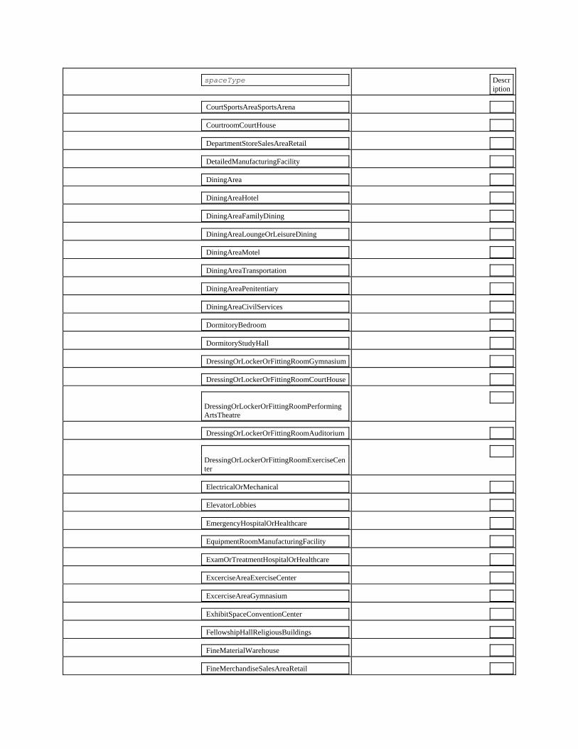
spaceType Description
CourtSportsAreaSportsArena
CourtroomCourtHouse
DepartmentStoreSalesAreaRetail
DetailedManufacturingFacility
DiningArea
DiningAreaHotel
DiningAreaFamilyDining
DiningAreaLoungeOrLeisureDining
DiningAreaMotel
DiningAreaTransportation
DiningAreaPenitentiary
DiningAreaCivilServices
DormitoryBedroom
DormitoryStudyHall
DressingOrLockerOrFittingRoomGymnasium
DressingOrLockerOrFittingRoomCourtHouse
DressingOrLockerOrFittingRoomPerformingArtsTheatre
DressingOrLockerOrFittingRoomAuditorium
DressingOrLockerOrFittingRoomExerciseCenter
ElectricalOrMechanical
ElevatorLobbies
EmergencyHospitalOrHealthcare
EquipmentRoomManufacturingFacility
ExamOrTreatmentHospitalOrHealthcare
ExcerciseAreaExerciseCenter
ExcerciseAreaGymnasium
ExhibitSpaceConventionCenter
FellowshipHallReligiousBuildings
FineMaterialWarehouse
FineMerchandiseSalesAreaRetail
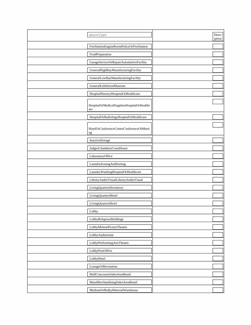
spaceType Description
FireStationEngineRoomPoliceOrFireStation
FoodPreparation
GarageServiceOrRepairAutomotiveFacility
GeneralHighBayManufacturingFacility
GeneralLowBayManufacturingFacility
GeneralExhibitionMuseum
HospitalNurseryHospitalOrHealthcare
HospitalOrMedicalSuppliesHospitalOrHealthcare
HospitalOrRadiologyHospitalOrHealthcare
HotelOrConferenceCenterConferenceOrMeeting
InactiveStorage
JudgesChambersCourtHouse
LaboratoryOffice
LaundryIroningAndSorting
LaundryWashingHospitalOrHealthcare
LibraryAudioVisualLibraryAudioVisual
LivingQuartersDormitory
LivingQuartersMotel
LivingQuartersHotel
Lobby
LobbyReligiousBuildings
LobbyMotionPictureTheatre
LobbyAuditorium
LobbyPerformingArtsTheatre
LobbyPostOffice
LobbyHotel
LoungeOrRecreation
MallConcourseSalesAreaRetail
MassMerchandisingSalesAreaRetail
MediumOrBulkyMaterialWarehouse

spaceType Description
MerchandisingSalesAreaRetail
MuseumAndGalleryStorage
NurseStationHospitalOrHealthcare
OfficeEnclosed
OfficeOpenPlan
OfficeCommonActivityAreasInactiveStorage
OperatingRoomHospitalOrHealthcare
OtherTelevisedPlayingAreaSportsArena
ParkingAreaAttendantOnlyParkingGarage
ParkingAreaPedestrianParkingGarage
PatientRoomHospitalOrHealthcare
PersonalServicesSalesAreaRetail
PharmacyHospitalOrHealthcare
PhysicalTherapyHospitalOrHealthcare
PlayingAreaGymnasium
PoliceStationLaboratoryPoliceOrFireStations
PublicAndStaffLoungeHospitalOrHealthcare
ReadingAreaLibrary
ReceptionOrWaitingTransportation
ReceptionOrWaitingMotel
ReceptionOrWaitingHotel
RecoveryHospitalOrHealthcare
RestorationMuseum
Restrooms
RingSportsAreaSportsArena
SleepingQuartersPoliceOrFireStation
SortingAreaPostOffice
SpecialtyStoreSalesAreaRetail
StacksLibrary
StairsInactive
Stairway
SupermarketSalesAreaRetail

spaceType Description
TerminalTicketCounterTransportation
WorkshopWorkshop
WorshipPulpitChoirReligious
<Surface> The Surface element is required. Surfaces can exist at the campus level and the building level. The GBS web service requires at least one Roof surface and one floor type surface to be allowed in the service. This is designed to ensure meaningful results will occur.
Minimum • Id – Attribute with a unique identifier for this surface
element. This identifier must be unique for the entire XML file.
• surfaceType – Enumerated attribute identifying the type of surface defined.
Table 5 – gbXML Surface Types and Characteristics
Surface Type Enumeration
Description Number of adjacent Spaces & Type
Tilt Range (outward normal vector - 0° faces up, 180° faces down)
Monoplanar Plane Location
InteriorWall Surface on the side of a space with an adjacent space on the other side of it.
Adjacent to two conditioned or unconditioned spaces.
45° to 149.99°
Centerline
ExteriorWall Surface on the side of a space with exterior conditions on the other.
Adjacent to one conditioned or unconditioned space and the outdoor environment.
45° to 149.99°
Outside
Roof Surface on top of a space and exterior conditions on the other.
Adjacent to one conditioned or unconditioned space and the outdoor
0° to 44.99° Outside

Surface Type Enumeration
Description Number of adjacent Spaces & Type
Tilt Range (outward normal vector - 0° faces up, 180° faces down)
Monoplanar Plane Location
environment.
InteriorFloor Surface on the bottom of an occupied space with an adjacent space below it.
Adjacent to two conditioned or unconditioned spaces.
150° to 180° Centerline
Shade Surface that is not in contact with any space.
Not adjacent to any spaces. The outdoor environment is on either side of the surface.
0° to 180° Centerline
UndergroundWall Below grade surface that is on the side of a space with earth contact on the opposite side of it.
Adjacent to one conditioned or unconditioned space and earth (soil).
45° to 149.99°
Outside (adjacent to soil)
UndergroundSlab Below grade surface that is on the bottom of a space with earth contact on the opposite side of it. Generally made from concrete.
Adjacent to one conditioned or unconditioned space and earth (soil).
150° to 180° Outside (adjacent to soil)
Ceiling
Surface that is on top of an occupied space with an unoccupied space above it.
Adjacent to two conditioned or unconditioned spaces.
0° to 44.99°
Centerline
Air Nonexistent surface used to “divide” large
Adjacent to two conditioned or unconditioned
0° to 180° Centerline

Surface Type Enumeration
Description Number of adjacent Spaces & Type
Tilt Range (outward normal vector - 0° faces up, 180° faces down)
Monoplanar Plane Location
spaces into smaller spaces separated by a air “surface”.
spaces. (Use Opening with openingType=’Air’ if adjacent to outside)
UndergroundCeiling Below grade surface that is on the top of a space with earth contact on the opposite side of it.
Adjacent to one conditioned or unconditioned space and earth (soil).
0° to 44.99° Outside (adjacent to soil)
RaisedFloor Surface on the bottom of a space with exterior conditions on the other side.
Adjacent to one conditioned or unconditioned space and the outdoor environment.
150° to 180° Outside
SlabOnGrade Surface on the bottom of a space with earth contact on the opposite side of it. Generally made from concrete.
Adjacent to one conditioned or unconditioned space and earth (soil).
150° to 180° Outside (adjacent to soil)
• AdjacentSpaceId – Element containing the id of the space or spaces (maximum of two) adjacent to this surface. Required for all surface types except shading.
• CADObjectId – Element containing the CAD applications unique identifier for this surface.
• PlanarGeometry - geometry of this surface. The PlanarGeometry element is described later in this document.

• RectangularGeometry – Rectangular geometry of this surface. The RectangularGeometry element is described later in this document.
Minimum
o Azimuth – see below for definition.
o CartesianPoint – see below for definition.
o Tilt – see below for definition.
o Height – see below for definition.
o Width – see below for definition.
• Opening - the opening element is described in the next section.
Optional • Name – Element with the name of this surface.
• Description – Element with the description of this surface.
• exposedToSun– Boolean type attribute used to determine if surface is exposed to the sun. True indicates that surface does have direct sun irradiation incident upon it at some point during the year. False indicates it does not. This does not include indirect sun irradiation. TIP - Setting this value, especially if there are a large number of exterior surfaces that do not see direct sun irradiation during the entire year can speed the EAM up significantly.
<Opening> The Opening element is required for surfaces with windows, doors, or air openings in them.
Minimum • Id – Attribute with a unique identifier for this surface
element. This identifier must be unique for the entire XML file.
• openingType – Enumerated attribute identifying the type of opening defined.
Opening Type Enumeration
Description Allowed Surface Types
FixedWindow Opening in a surface that is on the side of a space with a non-operable window in it.
InteriorWall, ExteriorWall, For an UndergroundWall add an ExteriorWall that is 1 cm larger than the

Opening Type Enumeration
Description Allowed Surface Types
window and place the window in it.
OperableWindow Opening in a surface that is on the side of a space with an operable window in it.
InteriorWall, ExteriorWall, For an UndergroundWall add an ExteriorWall that is 1 cm larger than the window and place the window in it.
FixedSkylight Opening in a surface that is on the top of a space with a non-operable window in it.
Roof, For an UndergroundCeiling add an Roof that is 1 cm larger than the skylight and place the skylight in it.
OperableSkylight Opening in a surface that is on the top of a space with an operable window in it.
Roof, For an UndergroundCeiling add an Roof that is 1 cm larger than the skylight and place the skylight in it.
SlidingDoor Opening in a surface that is on the side of a space with a sliding door in it.
InteriorWall, ExteriorWall, Ceiling, InteriorFloor, RaisedFloor, For an UndergroundWall add an ExteriorWall that is 1 cm larger than the door and place the door in it.
NonSlidingDoor Opening in a surface that is on the side of a space with a nonsliding door in it.
InteriorWall, ExteriorWall, Ceiling, InteriorFloor, RaisedFloor, For an UndergroundWall add an ExteriorWall that is 1 cm larger than the door and place the door in it.
Air Opening in a surface that has no window or door in it.
InteriorWall, ExteriorWall, Roof, UndergroundCeiling, Ceiling, InteriorFloor, RaisedFloor, For an UndergroundWall add

Opening Type Enumeration
Description Allowed Surface Types
an ExteriorWall that is 1 cm larger than the air opening and place the opening in it.
• CADObjectId – Element containing the CAD applications unique identifier for this opening.
• PlanarGeometry - the PlanarGeometry element is described in the next section.
• RectangularGeometry – Rectangular geometry of this opening. The RectangularGeometry element is described later in this document.
Minimum
o CartesianPoint – see below for definition.
o Height – see below for definition.
o Width – see below for definition.
Optional • Name – Element with the name of this surface.
<PlanarGeometry> The PlanarGeometry element is required for Surface and Opening elements as are the following elements and attributes contained in it.
Minimum • Id – Attribute with a unique identifier for this geometry
element. This identifier must be unique for the entire XML file.
• PolyLoop - the PolyLoop element is described in the next section.
Optional • Unit – Enumerated attribute identifying the unit of length and/or
coordinate measurement for geometry. Optional
o unit – lengthUnit type attribute specifying units of length or coordinates. Required if different from lengthUnit default defined in the gbXML element.

<PolyLoop> The PolyLoop element defines the shape and position of the surface. This element is made up of coordinates that describe a polygon in three dimensions. All coordinates must lie on the same plane. PolyLoop is required for Geometry as are the following element contained in it.
• CartesianPoint - the CartesianPoint element is described in the next section. There must be at least three CartesianPoint elements in each PolyLoop.
<CartesianPoint> The CartesianPoint element defines a three-dimensional point in space. At least three CartesianPoint elements are required for each PolyLoop as is the following element contained in it.
The vertice points defined with the CartesianPoint element must be in a counter-clockwise order with the outward normal vector (right-hand) pointing to the exterior side of the surface or opening.
For surfaces, vertice points that are within 4 inches of each other should be considered duplicate and one of them should be eliminated in the resulting CartesianPoint element.
• Coordinate – the Coordinate element is described in the next section. There must be exactly three Coordinate elements in each CartesianPoint.
<Coordinate> The Coordinate element defines the distance from the global origin to a point. Each CartesianPoint has three Coordinate elements. These describe the x, y, and z distances from the global origin, in order. Three Coordinate elements are required for each CartesianPoint.
<RectangularGeometry> The RectangularGeometry element defines the two-dimensional rectilinear components of surfaces and openings. This facilitates compatibility with applications that use this simple geometry rather than the more complex PlanarGeometry element. The surface or opening that is not rectilinear must be reduced to a rectilinear definition with the same area and aspect ratio as the original polygon.
• Azimuth – the Azimuth element contains the numerical degree value of the cardinal degrees from true north.
• CartesianPoint – the CartesianPoint element defines the distance of the surface origin relative to the building origin or the opening origin relative to the surface origin its in. See schema annotations for additional information.
• Tilt – the Tilt element defines the numerical degree value of the surface’s normal vector (using the right hand rule) to a vertical vector.
• Height – the Height element defines the height of the rectangular surface or opening. The product of the height

and width must equal the area of the surface. For nonrectalinear polygons the height and width will be for a virtual rectilinear surface.
• Width – the Width element defines the width of the rectangular surface or opening. The product of the height and width must equal the area of the surface. For nonrectalinear polygons the height and width will be for a virtual rectilinear surface.
<Results> The Results element will be populated by the EAM after any type of analysis with the appropriate results. This allows CAD developers to read in the results and present them using their interface standards. Green Building Studio, Inc. has recommendations to present various results in a way to communicate the relevant information in an informative and intuitive fashion on the model and are happy to met with you to present this information.
• Id – Attribute with a unique identifier for this geometry element. This identifier must be unique for the entire XML file.
• CADObjectIdRef - Attribute containing the CAD applications unique identifier for the CAD object this result is related to.
• ObjectIdRef – Attribute containing the identifier of the gbXML object element that these results are for.
• ResourceType – Enumerated attribute for identifying the resource type this Results element contains.
Table 6 - Resource Type enumerations. resourceType Description
Electricity
NaturalGas
Propane
FuelOil1
FuelOil2
FuelOil4
Water
ChilledWater
HotWater
Steam
• ResultsType – Enumerated attribute for identifying the result type this Results element contains.

Table 7 - Resource Type enumerations. resultsType Description
HeatLoad
CoolingLoad
CO2
SO2
NOx
Energy
Power
Cost
EnergyCost
DemandCost
CommodityCost
TransportationCost
DryBulbTemperature
WetBulbTemperature
DewPointTemperature
FootCandles
Humidity
MoistureContent
Flow
• StartTime – Attribute defining the time for the first value element in this results element. Uses ISO 8601 extended format http://www.w3.org/TR/xmlschema-2/#dateTime.
• timeIncrement – Element defining the increment of time between multiple value entries. Uses ISO 8601 extended format http://www.w3.org/TR/xmlschema-2/#duration.
• Unit – Attribute defining the units of measure for this result value.
• Currency – Enumerated attribute for specifying the unit of currency the cost result is using.
Table 8 - Currency enumerations. Currency Description
USDollars

Currency Description
CanadianDollars
Pesos
Euros
Yen
IndianRupee
Yuan
TaiwanDollar
EnglishPound
Mark
Franc
Ruble
Real
NewZealandDollar
AustralianDollar
• Value – Element containing the actual numerical result value. If multiple values are entered for time series data they are comma separated.

EAM Object Rules Space The EAM uses the gbXML Space element to define actual building spaces which are analogous to rooms. A space has to have a building parent whose building type is defined.
Surface The EAM uses the gbXML Surface element to define the surfaces bounding a space or shading a building.
A surface described with the Surface element can be adjacent to a maximum of two spaces. Vertical and horizontal clipping must be done with surfaces that are adjacent to more than two spaces as illustrated in figure 2 on the following pages. Once all horizontal clipping is completed, the number of adjacent spaces to a surface dictates if the surface is an interior, exterior, or shading surface.
If a surface is adjacent to two spaces then it is an interior surface, and two SpaceId elements are used to reference the Identifier for the adjacent spaces. If a surface is adjacent to only one space then it is an exterior surface, and only one SpaceId element is used. If a surface is not adjacent to any space then it is a shading surface.
The geometry element child of this element describes the surface plane of the surface. For this geometry element use the center plane of interior and shading surfaces and the outside plane of exterior surfaces. All surfaces should be planar. When attempting to describe a curved or other non-planar surface, the surface should be faceted, then broken into smaller planar surfaces that comply with the above rules. TIP: as a general rule, course facets are preferred in order to reduce simulation time. The right-hand rule is used for exterior surfaces in determining the outward normal.
Thermal Model Development Overview In this section we will describe the steps necessary for reducing a complex building into a model that is used for calculating its thermal loads as well as its energy use using a simulation program such as DOE-2 or EnergyPlus.
The method described here is what a typical engineer would do in determining the necessary parameters and their values in building a thermal model. This is quite different and a bit more complex then what an average HVAC engineer does today to calculate the thermal loads of a building in sizing the HVAC equipment for that building.
The Process
Take Offs The first thing an engineer requires is a set of plans for the building they would like to model.
The ideal set of plans includes the following.
• Floor plans for each floor of the building.
• Elevations for each orientation of the building including inter-building areas such as courtyards.
• Mechanical drawings for each floor including schedules of equipment.
• Electrical drawings for each floor which includes schedules of lighting and other internal load generating equipment.
• Architectural schedules and details which show all envelope details including but not limited to insulation levels, fenestration properties and shading devices.
• Specification documents including performance minimums for equipment and energy-code related items.
Define Building Envelope and Constructions With the plans in their possession the engineer will go about the task of defining by floor each unique space. This is done in the following way. This phase of model construction is similar to what the EAM expects of the CAD tool.
1. Identify the origin to be used for all measurements on the plan. Determine the location of the building including its zip code.
2. Identify unconditioned spaces versus conditioned spaces. This is done by the descriptions of the spaces and the mechanical drawings.
3. Identify space types (office, hallway, conf. room) by space descriptions or layouts.
4. Group similar small spaces by similar external envelope thermal loads and HVAC schedules into simulated spaces. Similar external envelope thermal loads are determined by wall constructions and orientation. On a large floor with windows on each side, there are typically zones for each perimeter orientation and a core zone. Perimeter zones are typically about 15 feet deep.
5. If there is a large space that has large interior openings separating the space into smaller spaces use these openings as virtual walls (air walls) to cut the larger space into smaller spaces. This is done when a large space has either of the following.
Exterior walls that have multiple and unique exposures to different Cartesian directions.
Clearly defined unique mechanical HVAC needs to separate parts of the space often indicated by multiple thermostats in the

large space. An airport gate area is a good example of this.
6. For each space or grouped spaces, use the end-point vertices at the floor of each space’s enclosing walls to develop the floor polygon of the space. Exterior walls are measured on their exterior plane and interior walls are measured on their centerline plane. Interior walls are extended to an exterior wall’s exterior plane for their connecting coordinate and to an interiors center plane. Do the same at the ceiling/roof to develop the ceiling/roof polygon.
7. Calculate the actual area of the space based on the area of the floor polygon developed in the previous step.
8. Spaces with multi-levels will need to be simplified by making them into a single floor (eg. a theatre with a stage) that spans several levels, if the difference in height between each level is equivalent to a new floor (eg. a mezzanine), that section of the floor will be divided into two spaces, one over the other, and with an air-type interior wall separating them. This stacked space approach is required in a CAD tool if its space object can not accommodate spanning multiple floors.
9. For unspecified volumes the engineer will assume it is a large unconditioned space by deciding whether the space can be occupied based on height. If it is too low for people to stand in then it is most likely an unconditioned space. If the height is less than approximately two feet then it is assumed to be a thick construction and will be modeled in its entirety as a surface.
10. The floor and the ceiling planar polygon surfaces will need to be divided depending on what is adjacent to them. For instance, the floor may cantilever over an exterior walkway as well as two spaces below it. The floor polygon will then be divided into three floor polygons, one for the cantilever portion, and two for each space the floor is over. The rules for dividing space surfaces are described in the EAM Object Rules section above.
11. Determine the average height of the ceiling for the space and use this height along with the space area to calculate the estimated space volume. The simulation results are not highly sensitive to variations in the volume of spaces; so do not be concerned with the errors introduced by averaging the height of the ceiling.

12. For each wall enclosing the space define the surface width, height, azimuth, and the planar polygon of each wall’s surface representation. Divide the wall up for unique orientations and constructions. Also, apply the rules mentioned above for floors and ceiling for adjacent spaces. For example, in Figure 2, Room C has a skylight well with walls adjacent to Plenum B. These walls will need surfaces defined for them that are adjacent to Room C and Plenum B.
13. Determine the openings for all surfaces enclosing the space including windows, doors, and skylights. Measure the height and width as well as the polygons for each of these openings.
14. For exterior walls and windows where there exists any exterior shading surfaces that are attached to the wall or window and are unique to that wall or window, define these surfaces as shading surfaces with their height, width and polygon.
15. Determine surfaces that shade more large portions of the building that are not unique to any one space wall or window. Define those surfaces as shading surfaces with their height, width and polygon.
16. Determine if an adjacent structure or vegetation will shade the building and construct a planar surface that simulates that shading structure. Define the polygon for the planar structure and give it a name. Note that most energy analysis for code compliance require that these types of shades should be ignored.
17. Determine the thermal and optical properties of all surfaces and build material and construction “libraries” that will be assigned to each wall, floor, ceiling and roof in the building. Do the same with windows, doors, and skylights.
Define Building Systems and Operation This phase of model construction becomes more complex and departs from normal information contained in plans or a CAD model. The EAM does not expect CAD systems to produce the information discussed in the following two sections.
18. Determine the types, location, and efficacy of the lighting systems for each space. Also, determine any significant electrical or fuel using equipment’s energy use in the space such as computers, copiers, printers, or cooking equipment.
19. Determine usage schedules for operational characteristics including lighting, plug loads

(receptacles), infiltration, occupancy, HVAC fans (on/off), thermostats, outside ventilation air and numerous others. These schedules are based on either actual operation or energy code based assumptions.
20. Define HVAC systems that are the nearest equivalent to the actual systems being existing or being contemplated for a building. This includes defining heating fuels, air vs. water systems, efficiencies for the system components, sizing, control parameters (based on temperature, humidity, enthalpy, time of day or season).
21. Assign the simulated spaces to simulated HVAC zones based on a many to one correspondence. Assign each of these HVAC zones to one and only one HVAC system.
22. If required, assign HVAC systems defined in number 18 to an appropriate central plant chiller and/or boiler system. Some system types, for example residential air conditioners, do not have a central plant.
Iterative De-bugging, Syntax and Error Checking 23. Run the simulation with the appropriate weather file
based on the building’s location (zip code), de-bug, extract results, check for reasonableness of results and refine assumptions and simulation detail if necessary.
EAM Limits
DOE-2 Limits Below are listed the limits for DOE-2 building components with their comparable gbXML elements.
DOE-2 Command
gbXML Element Max Number
Building-Shade & Fixed-Shade
Surface surfaceType: Shade
1024
Construction Construction 8192
Layers Layer 8192
Material Material 8192

Glass-Type Glaze 1024
Space Space 4096
Exterior-Wall Surface surfaceType: ExteriorWall, Roof, RaisedFloor
8192
Interior-Wall Surface surfaceType: InteriorWall, InteriorFloor, Ceiling
8192
Underground-Wall
Surface surfaceType: UndergroundWall, UndergroundSlab, UndergroundCeiling
8192
Window Opening openingType: FixedWindow, OperableWindow, FixedSkylight, OperableSkylight
8192
Door Opening openingType: SlidingDoor, NonSlidingDoor
1024
Zone Zone 4096


Appendix D - Beta Test Report


Beta Test Report for Conceptual Design Energy Analysis Tool Phase III
Contract #: 500-04-020 January, 2007
Contractor Project Manager: John Kennedy Commission Project Manager: Norm Bourassa
Introduction A series of internal and external testers were used to test the updated Green Building Studio web site, web service, the updated gbXML plug-in for Autodesk’s Architectural Desktop, the updated gbXML plug-in for Graphisoft’s ArchiCAD, and CAD vendor’s gbXML functionality. The public beta testing for the Green Building Studio (GBS) web service began in February 2006 and concluded in May 2006 resulting in a public launch in June 2006 of version 2.0. The beta testing of the GBS is an enormous task and one that this project could never fully execute with the limited time and budget. To fully appreciate the enormity of this task keep in mind that the GBS is written using over 10 programming languages and can be accessed by no less than eight different CAD application versions running on several different operating systems. In this report we summarize all the testing completed, list the issues that were identified, resolved, and are outstanding. A discussion is also included on the current status of all gbXML plug-ins.
Testing Methodology Because the beta test task has very limited budget and time an approach to beta testing had to be implemented that was very cost effective in addressing the majority of issues to be found. With that in mind the beta test was started once internal testing was sufficient enough where successful runs were made our updated system using our standard test models. The initial internal tests comprised of white box testing by the developers. The black box testing began with our contracted quality assurance (QA) engineer as well as our engineers for database integrity, and then continued with end users once code was approved by the team and the QA engineer. White box testing is the type of testing that is conducted with all code available for debugging when issues are discovered. Black box testing occurs primarily at the end user perspective and where no code is available for determining how an issue can be resolved. An issue tracking system is essential in a black box testing environment to allow issues to be logged and resolved by the development team. We used and continue to use TestTrack Pro for internal and external issue logging and tracking.

Several components of the Green Building Studio were tested during the beta testing task. These components included internal components, plug-ins developed by subcontractors, and gbXML files produced by CAD Vendor’s development efforts. The components tested are listed below.
Components tested. 1. Green Building Studio web site 2. Green Building Studio web service including the Energy Analysis Module 3. Green Building Studio Client 4. gbXML plug-in for Autodesk Architectural Desktop 5. gbXML plug-in for Graphisoft ArchiCAD on the Mac OS 6. gbXML plug-in for Graphisoft ArchiCAD on the Windows OS 7. gbXML files from Revit
The components listed above were tested using the white and black box approaches and using different testing tools and users. The testing process flow is diagrammed in the following flow diagram.
In the above diagram issues that were found at later stages in the testing did not always require going through the entire process diagramed above. This was determined on an ad hoc basis. The testing phases and their approaches on all the components are outlined below.
Tests Conducted 1. White box testing of Green Building Studio web site. 2. White box testing of Green Building Studio web service.
White Box Testing
Black Box Testing By Engineers
Installation Testing
Simulation Testing
Black Box Testing By Beta Testers
Issue Logging
Issue Assignment
Issue Tracking
Issue Resolution

3. White box testing of Green Building Studio web service and GBS Client. 4. Black box testing of following components using the listed tools.
a. WinRunner testing of Green Building Studio web site. b. WinRunner testing of Green Building Studio web service. c. WinRunner testing of Green Building Studio Client.
5. Installation testing of gbXML plug-ins for Autodesk Architectural Desktop. 6. Installation testing of gbXML plug-ins for Graphisoft ArchiCAD. 7. Successful runs of DOE-2 simulations for all energy code regions supported by database. 8. Manual testing of CAD Vendor gbXML files running through the GBS. 9. Manual testing of several EnergyPlus idf files that were created by GBS.
Testing and Results Testing of Web Site Manual testing was the most common testing for the updated web site which was at the recommendation of the QA Engineer who originally tested the first web site. WinRunner testing was also used for stress testing various parts of the web site. Silk is a script tester that allows the QA engineer to write a script on what to test for each web page and every control or response on the web page. Once this script is written the QA engineer runs it and determines if any errors are produced. If errors or issues are found they are logged and fixed, then testing resumes. An example of the test plan detail is seen below.
Test Case Number: 5.2
New User Registration Page

Page: http://development.greenbuildingstudio.com/Register.aspx Inputs: Input Name Type Max Size Required Username Textbox 50 char Yes Password Textbox 50 char Yes First Name Textbox 50 char Yes Last Name Textbox 50 char Yes eMail Address Textbox 50 char Yes Title Textbox 50 char Company Textbox 50 char Phone Textbox 20 char Address1 Textbox 50 char Address2 Textbox 50 char City Textbox 50 char State/Province Textbox 50 char Country Textbox 50 char Zip/Postal Code
Textbox 10 char
Primary 3D-CAD
Drop down 3D Studio MAX, 3D Studio Viz, AllPlan, ArchiTECH, Arris Architect, Arris CAD, Artifice DesignWorkshop, Autodesk Architectural Desktop, Autodesk AutoCAD, Autodesk Building Systems, Autodesk Revit, Bentley Architectural Design,
Yes

Application Bentley HVAC, Bentley Microstation, Bentley Microstation TriForma, BuildersCAD, DataCAD, Form Z, MicroGDS, Graphisoft ArchiCAD, IntelliCAD, PowerCADD, SketchUp, TurboCAD, VectorWorks, Virtus, Other, Do not use 3D CAD
Your Job Function Drop down Architect, Draftsperson, Engineer, IT Manager, Manager, Sales/Marketing, Other Yes Organization Type Drop down Architectural, Engineering, Design & Construction Firm, Construction Firm,
Facility Operations, Manufacturer, NGO, Utility, Academic, Other Yes
Organization Size Drop down over 500, 101-500, 51- 100, 10-50, under 10 Yes
Page Title “Register”
Table Title- “Login”
“User Name” static text
“User name” text field
Valid/Invalid data
“Password”
Valid/Invalid data
“Re-enter Password”
Valid/Invalid data
Table Title “Contact Data”
“First Name” static text/“First Name” text field
Valid/Invalid data TBD
“Last Name” static text/“Last name” text field
Valid/Invalid data TBD
“Email Address” static text/“Email Address” text field
Valid/Invalid data TBD
“Re-enter Email” static text/“Re-enter Email” text field
Valid/Invalid data TBD
“Title” static text/“Title” text field
“Company” static text/“Company” text field
Valid/Invalid data TBD
“Phone” static text/“Phone” text field
Valid/Invalid data TBD
“Address 1” static text/“Address 1” text field
Valid/Invalid data TBD
“Address 2” static text/“Address 2” text field
Valid/Invalid data TBD
“City” static text/“City” text field
Valid/Invalid data TBD

“State/Province” static text/“State/Province” text field
Valid/Invalid data TBD
“Country” static text/“Country” text field
Valid/Invalid data TBD
“Zip/Postal Code” static text/“Zip/Postal Code” text field
Valid/Invalid data for Zip/Postal Code
“Primary 3D-CAD Application” drop down list
Items
Table Title “Job Information”
“Your Job Function” text and dropdown list Verify all items from dropdown list (see metrix bellow)
“Organization Type” text and dropdown list (see metrix bellow) Verify all items from dropdown list (see metrix bellow)
5.2.3.3. “Organization Size” text and dropdown list 5.2.3.3.1. Verify all items from dropdown list
Push button “Next”
Push button “Back”
Push button “Reset”
Page: http://development.greenbuildingstudio.com/Register.aspx Inputs: Input Name Type Max Size Required Username Textbox 50 char Yes Password Textbox 50 char Yes First Name Textbox 50 char Yes Last Name Textbox 50 char Yes eMail Address Textbox 50 char Yes Title Textbox 50 char Company Textbox 50 char Phone Textbox 20 char Address1 Textbox 50 char Address2 Textbox 50 char City Textbox 50 char State/Province Textbox 50 char Country Textbox 50 char Zip/Postal Code
Textbox 10 char
Primary 3D-CAD
Drop down 3D Studio MAX, 3D Studio Viz, AllPlan, ArchiTECH, Arris Architect, Arris CAD, Artifice DesignWorkshop, Autodesk Architectural Desktop, Autodesk AutoCAD, Autodesk Building Systems, Autodesk Revit, Bentley Architectural Design,
Yes
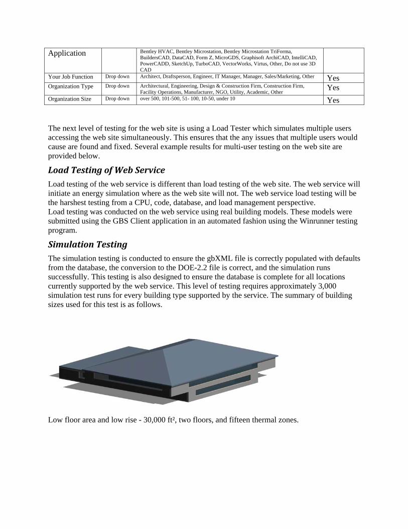
Application Bentley HVAC, Bentley Microstation, Bentley Microstation TriForma, BuildersCAD, DataCAD, Form Z, MicroGDS, Graphisoft ArchiCAD, IntelliCAD, PowerCADD, SketchUp, TurboCAD, VectorWorks, Virtus, Other, Do not use 3D CAD
Your Job Function Drop down Architect, Draftsperson, Engineer, IT Manager, Manager, Sales/Marketing, Other Yes Organization Type Drop down Architectural, Engineering, Design & Construction Firm, Construction Firm,
Facility Operations, Manufacturer, NGO, Utility, Academic, Other Yes
Organization Size Drop down over 500, 101-500, 51- 100, 10-50, under 10 Yes The next level of testing for the web site is using a Load Tester which simulates multiple users accessing the web site simultaneously. This ensures that the any issues that multiple users would cause are found and fixed. Several example results for multi-user testing on the web site are provided below.
Load Testing of Web Service Load testing of the web service is different than load testing of the web site. The web service will initiate an energy simulation where as the web site will not. The web service load testing will be the harshest testing from a CPU, code, database, and load management perspective. Load testing was conducted on the web service using real building models. These models were submitted using the GBS Client application in an automated fashion using the Winrunner testing program.
Simulation Testing The simulation testing is conducted to ensure the gbXML file is correctly populated with defaults from the database, the conversion to the DOE-2.2 file is correct, and the simulation runs successfully. This testing is also designed to ensure the database is complete for all locations currently supported by the web service. This level of testing requires approximately 3,000 simulation test runs for every building type supported by the service. The summary of building sizes used for this test is as follows.
Low floor area and low rise - 30,000 ft², two floors, and fifteen thermal zones.

Low floor area and high rise - 40,000 ft², four floors, and twenty thermal zones.
High floor area and low rise - 270,000 ft², three floors, and twenty seven zones.
High floor area and high rise - 300,000 ft², four floors, and twenty thermal zones.

Each building file above was edited for different building types and locations. Every gbXML Building type enumeration was run as well as a zip code for every location the database supports currently at 34 regions. This level of testing will ensure every record of the database has values defined for the required construction, internal gain, schedule of operation, air loop equipment, and hydronic equipment. Several runs were found to fail through this testing, and upon further investigation it was determined to be caused by DOE-2 related warnings that were being misreported as errors. A new version of DOE-2 resolved this issue.
Beta Testing Internal beta testing for the tool began as early as September on the web site and GBS Client. Beta testing began in February with testers at Autodesk, Graphisoft, Xanadu, Encina, AEC, HOK, Lawrence Technical University, and Green Building Studio, Inc.. A public beta test started in February 2006 and ended in May 2006 with several realistic buildings and projects being submitted to the service. The 24 beta testers made 49 attempts to submit gbXML files to the Green Building Studio with 15 of those submissions failing. The majority of these failures were attributed to gbXML plug-in inaccuracies associated with either bugs in the CAD’s gbXML functionality or incomplete CAD models. During this period, Pacific Gas & Electric Company’s GBS Evaluation project consultants, Architectural Energy Corporation, conducted several tests on the service as well as shortly after the release of the service. Numerous issues were discovered by them and most were addressed in the 2.2 release of the service. These issues are listed below.
• Missing Plug loads – Fixed with v.2.1 • Air-side Economizer – Fixed with v.2.2 • Air Infiltration – Fixed with v.2.2 • Outside air amounts – Fixed with v.2.2 • Thermostats – Fixed with v.2.2
During the beta test very few technical support inquiries were made. The majority of these support issues were related to the following items.
• Issue: Installation issues associated with the GBS Client software. Solution: The solution varied based on the users system and network with a simple reboot fixing it to not finding a solution. We will be adding the ability for someone to add a gbXML file on the run list web to alleviate the need for the GBS Client in the future.
• Issue: Absence of equipment loads in simulation. Solution: A schedule coding issue caused this issue. It was resolved as soon as it was reported.
• Issue: Economizers were missing from most building sizes. Solution: The code and database were modified to ensure an economizer has been added to most HVAC systems serving large building sizes.

• Issue: Outside air portions were written in a duplicate fashion in the DOE-2 input file where it was causing too much outside air. Solution: The code was modified to ensure only one Outside air code word was written.
• Issue: Thermostats were being defaulted to what DOE-2 uses. Solution: Explicitly write the desired thermostat values to prevent using the DOE-2 default, which could be inappropriate.
• Issue: A minimum flow ratio was not specified for the DOE-2 input file. Solution: The minimum flow ratio is now specified for all Variable Air Flow type systems.
• Issue: There were some unit conversion issues associate with construction values. Solution: This was caused by new database records that were entered as SI, but were not specified in the database as being in SI units. This was fixed.
Current Outstanding Issues
Green Building Studio web site and service The Green Building Studio web site currently has the following outstanding issues.
• Occasionally a new user’s validation email is bounced back by their Internet Service Provider. We are exploring using a validated email service to prevent this type of bounced email from occurring. It will no doubt increase our operating costs.
• Most of the BIM tools that support gbXML also support exporting shades. Unfortunately, the rich shades that are in the gbXML file have to be reduced to rectangles in the DOE-2 file as it does not support polygons of more then 4 vertices as illustrated in the following two diagrams.
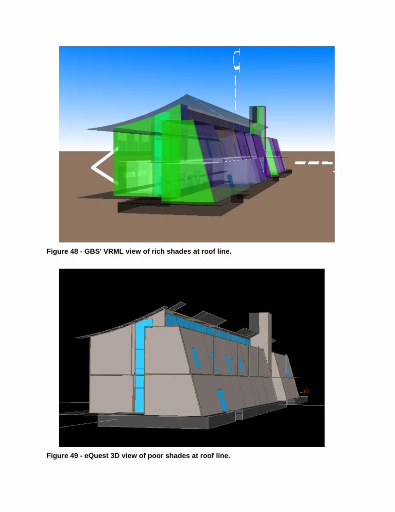
Figure 48 - GBS' VRML view of rich shades at roof line.
Figure 49 - eQuest 3D view of poor shades at roof line.

Graphisoft ArchiCAD gbXML plug-in Current outstanding issues are listed below.
• ArchiCAD 10 allows for walls to be projected on multiple floors alleviating the user from having to define them on other stories. The gbXML plug-in currently does not recognize them. It is being enhanced to see them.
Autodesk Architectural Desktop gbXML plug-in Current outstanding issues are listed below.
• Because the ADT product is so extensive we could not possibly thoroughly test the plug-in, but we have seen strange gbXML file being produced by this plug-in.