the mental canvas: a tool for conceptual architectural...
TRANSCRIPT
The Mental Canvas: A Tool for Conceptual Architectural Design and Analysis
Julie Dorsey Songhua Xu Gabe Smedresman Holly Rushmeier Leonard McMillan§
Department of Computer Science §Department of Computer ScienceYale University The University of North Carolina at Chapel Hill
Abstract
We describe a computer graphics system that supports con-ceptual architectural design and analysis. We use as a start-ing point the traditional sketchbook drawings that archi-tects use to experiment with various views, sections, and de-tails. Rather than interpret or infer 3D structure from draw-ings, our system is designed to allow the designer to orga-nize concept drawings in 3D, and gradually fuse a seriesof possibly geometrically-inconsistent sketches into a set of3D strokes. Our system uses strokes and planar “canvases”as basic primitives; the basic mode of input is traditional2D drawing. We introduce methods for the user to controlstroke visibility and transfer strokes between canvases. Wealso introduce methods for the user to position and orientthe canvases that have infinite extent. We demonstrate theuse of the system to analyze existing structures and conceivenew designs.
1 Introduction
Architects use drawing as an aid to visual thinking in analy-sis and design. Drawings at various levels of detail allow thedesigner to both work through how an existing structure fitstogether, and to collect and refine ideas for new buildings.Existing CAD systems have been extraordinarily success-ful in the late stages of building design and construction.However, because they require the specification of geome-try with great accuracy, they have not proven suitable foranalysis and conceptual design. In this paper we presenta system that uses the idea of a 3D sketch as the founda-tion for a representation of a building. Our system closelyfollows the traditional 2D drawing process in analysis anddesign, and adds capabilities for the user to fuse the drawnelements into a 3D structure.
In architectural design, the processes of analysis of existing
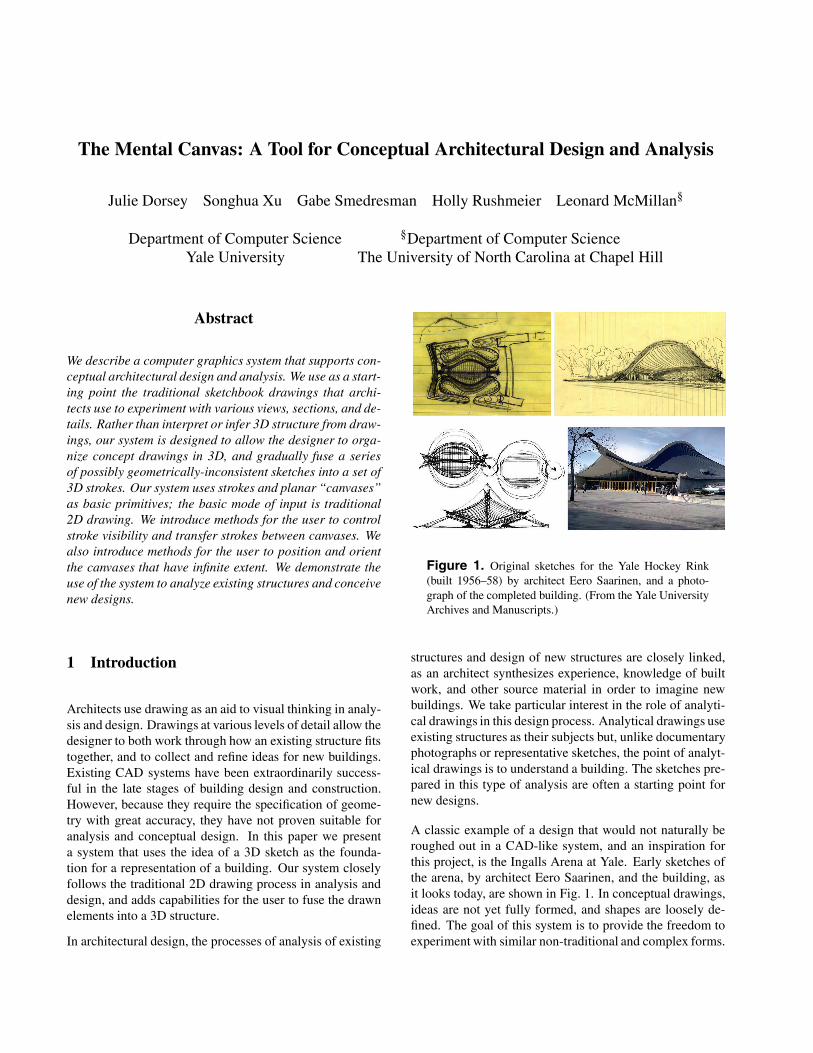
Figure 1. Original sketches for the Yale Hockey Rink(built 1956–58) by architect Eero Saarinen, and a photo-graph of the completed building. (From the Yale UniversityArchives and Manuscripts.)
structures and design of new structures are closely linked,as an architect synthesizes experience, knowledge of builtwork, and other source material in order to imagine newbuildings. We take particular interest in the role of analyti-cal drawings in this design process. Analytical drawings useexisting structures as their subjects but, unlike documentaryphotographs or representative sketches, the point of analyt-ical drawings is to understand a building. The sketches pre-pared in this type of analysis are often a starting point fornew designs.
A classic example of a design that would not naturally beroughed out in a CAD-like system, and an inspiration forthis project, is the Ingalls Arena at Yale. Early sketches ofthe arena, by architect Eero Saarinen, and the building, asit looks today, are shown in Fig. 1. In conceptual drawings,ideas are not yet fully formed, and shapes are loosely de-fined. The goal of this system is to provide the freedom toexperiment with similar non-traditional and complex forms.
This requires a different approach focusing on how a usercan organize ideas in 3D, rather than on many current ef-forts in sketching research that attempt to interpret simplesketches as 3D shape.
Typically sketches are 2D representations of a 3D idea, butthere is no defined “middle ground” or information that“goes between” the sketch and the object. It is often difficultto interpret a 2D sketch whose 3D implications are not clear,and the existing array of computational aids offers little as-sistance in this task. The incompleteness of a sketch oftenmakes it impossible to resolve ambiguities without furtherinput from the user, and it is even difficult to offer an intu-itive way for the user to provide that information. For themost part, these difficulties have been passed over by 3Dmodeling and visualization programs that instead choose toaddress the needs of those users who already have a well-defined 3D object in mind.
In our proposed approach, the user begins with a draw-ing in 2D, without any initial specification of positions orviews, or any automatic inference of perspective or primi-tive shapes. We allow the user to then position these draw-ings in 3D space, as one would tack up paper sketches on abulletin board. The user can begin fusing and consideringviews together by transferring individual drawn strokes ontonew planes other than the one on which they were drawn.We assist in this process by giving the user controls overstroke visibility from different views, and giving convenientcontrols over plane positioning and orientation. The usergradually builds and refines a set of 2D planes, containingstrokes, to form a 3D sketch space.
The rest of the paper is organized as follows. We begin witha review of relevant previous work. We then describe thebasic features of our proposed system. As a demonstrationof the system functions, we show the development of sev-eral 3D stroke assemblies. We then go on to demonstratethe primary uses of the system: analysis of existing struc-tures and developing new designs. We conclude with ideasfor future directions in this area, based on the experience ofarchitectural students using the system.
2 Previous work
The earliest computer-based sketching system dates backto the pioneering contribution by Sutherland [18], which iswidely considered as the first complete graphical user inter-face. His system, equippedwith a light pen and a plotter dis-play, allowed sketching of 2D technical illustrations for de-sign applications. Sachs et al. first introduced 3D drawingto the community of computer graphics [14] in 1991. Re-search on sketching in computer graphics has since grown
to include a variety of topics, including achieving the “look”of traditional sketches [6, 15, 16, 22], sketching abstractconcepts [23], and 2D tools for artistic expression. Here,we focus on previous work specifically related to 3D de-sign.
Our work is related to prior efforts in digital perspectivesketching. Piccolotto [13] introduced perspective sketchingon a tilting pen-based table display as an electronic tool forearly architectural design and for detecting geometric formsin the input. Cohen et al. [4] explored the interesting ideaof 3D curve sketching, which requires the user to specifythe image-space projection of the curve and its shadow on ahorizontal surface. In the 3D6B editor proposed by Kallio[10], 2D input strokes are projected to the grid surface cho-sen by the user. However, no post-creation transformationor alteration of strokes is allowed, and a great amount oftime is required to produce a 3D sketch. In comparison, oursystem offers a gradient from 2D to 3D design work: theuser chooses to transform the initial 2D sketch drawings tothe corresponding 3D forms at any time. In addition, thestroke editing functions supported by our system providethe flexibility to gradually refine the sketches and resolveambiguities as needed. This matches the cognitive processof conceptual design, as an architect moves from prelimi-nary ideas toward precisely defined models.
Our work is also related to early work in gestural interfacesfor modeling, like the SKETCH system [23] and Teddy [8].SKETCH creates geometry by mapping gestural input tomodeling functions. Teddy infers freeform 3D polygonalsurfaces from drawn input. Igarashi and Hughes [7] pro-posed an interface for 3D drawing based on a set of parallelworking suggestion engines. A related idea was explored byTsang et al. [21], who wrote a system to accept input andto suggest similar geometries from a database. In their sys-tem, 2D images were introduced as a guide for the sketch-ing process, which can attract, smooth, and resample inputcurves. This system mainly reuses existing shapes, eithercaptured in the form of images or contained in the geomet-ric database. In our stroke-based system, no geometry isintroduced that the user has not explicitly specified.
Tolba et al. introduced a system [19, 20], where user enteredstrokes are represented as projective strokes: stroke pointsare projected onto a unit sphere surrounding the viewer.This leads to the capability of reprojecting the strokes tosimulate camera motion, thus making the changing of view-point possible. As a result, panning, tilting and zoomingare effectively supported even though no true 3D geometrymodel is ever constructed. Our new system moves beyondstrokes on the unit sphere to placing strokes freely in 3Dspace.
There is also previous work in using non-conventional
primitives like strokes or planes as a lightweight model-ing framework. Cohen et al. [3] proposed a system calledHarold, which creates a visually rich virtual world made ofstrokes using an extended billboard technique. This systemis not concerned with the iterative refinement of ambigu-ous sketches for capturing and stimulating design ideas inthe early stages. Ijiri et. al. employed a collection of 2Dstrokes, which are used as a guide for the 3D modeling offlowers [9]. Bourguignon et al. introduced a system wherestrokes are visible from one direction and gradually disap-pear as the camera rotates [2]. Decoret et al. [5] success-fully simplified complicated geometric models into a set ofrepresentative planes, which they called billboard clouds.Their work is inspired by the prior practices of scene mod-eling through textured clusters [11] and layered depth im-ages [17]. Unlike our work, these efforts focused on effi-cient scene modeling and rendering, but didn’t emphasizethe support for a fluid scene design and refinement process.
The core idea driving the development of our system is toallow a user to develop coherency in 3D gradually. Theo-retically the same process could be carried out in an exist-ing CAD system. However CAD systems are designed tocreate well-defined 3D models, and then automatically ren-der views of them, rather than letting the user draw a viewfrom scratch. The design software Autodesk AliasStudiotried to bridge this difference. However in the AliasStu-dio, sketches serve only as transparent overlays to guide3D model creation by traditional means. Our work focuseson allowing the user to draw 3D shapes as an assembly ofgestural strokes, and to easily draw, edit, and refine thosestrokes.
3 System Description
A 3D sketch in our system is built out of invisible planar2D surfaces, which we call canvases. These canvases canbe positioned and rotated in 3D space, using the traditionalCAD tools of position, rotate, and scale, on three coordinateaxes, using the tablet pen. Though they are theoreticallyinfinite in extent, they are drawn with finite borders so thatthe user can easily see their orientation onscreen. Only onecanvas can be active at any time. A canvas is made activeby clicking on the corner of its onscreen border.
The user draws with the tablet pen, and sets down strokesdirectly on the active canvas. By rotating the camera viewwith the arrow keys on the keyboard, the user can draw ona canvas from any angle; the pen position is automaticallyprojected onto the appropriate point on the canvas surface.
For quickly exploring new ideas or changes, a view canvascan be created. View canvases act like acetate transparen-
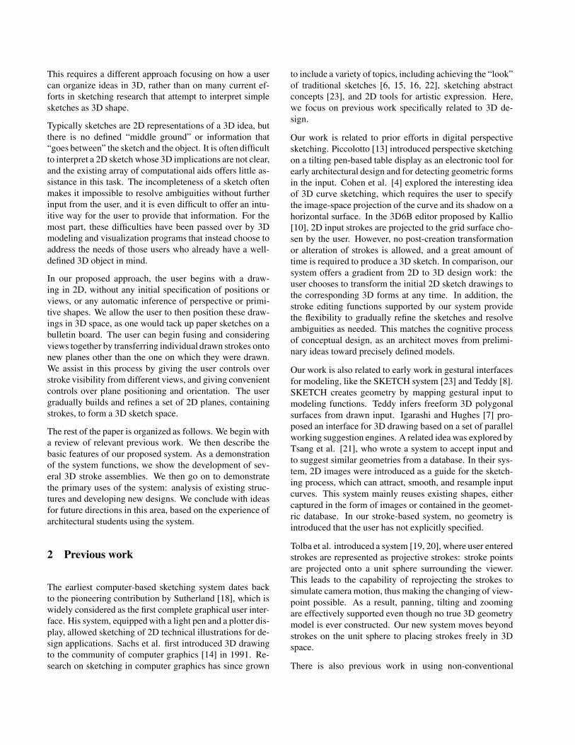
(a) (b) (c)
Figure 2. Pre-configured canvas assemblies provided byour system: parallel (a), co-axial (b) and ring (c). The blueplanes indicate the currently active canvas.
(a) (b)
Figure 3. The user can draw strokes in an orthographic2D window and the system will map the drawing onto theselected canvas.
cies locked to the camera’s near plane, and provide func-tionality for quick sketching in 2D, over a view of a 3Dobject, without defining a volume or worrying about depth.View canvases are bookmarked to a certain view of the 3Dobject and, once properly oriented, are not meant to be re-aligned.
Strokes can be pushed from a view canvas onto a 3D can-vas using perspective projection. The user enters selectionmode, draws a box around the strokes to be pushed, thenselects a target canvas. These strokes are then pushed ontothe target canvas in such a way that they appear no differ-ent from the view canvas viewpoint, but lie flat on the targetcanvas surface. The results are exactly the same as theywould be if the user had drawn the strokes directly on thetarget canvas.
3.1 Core Features
Our system is based on managing canvases, entering strokesand manipulating existing strokes. Each of these operationsrequired the creation of new user interaction concepts.
Managing canvases. To help the user get started quickly,the system provides a few built-in 3D assemblies of can-vases in common arrangements: axial cross-sections, paral-
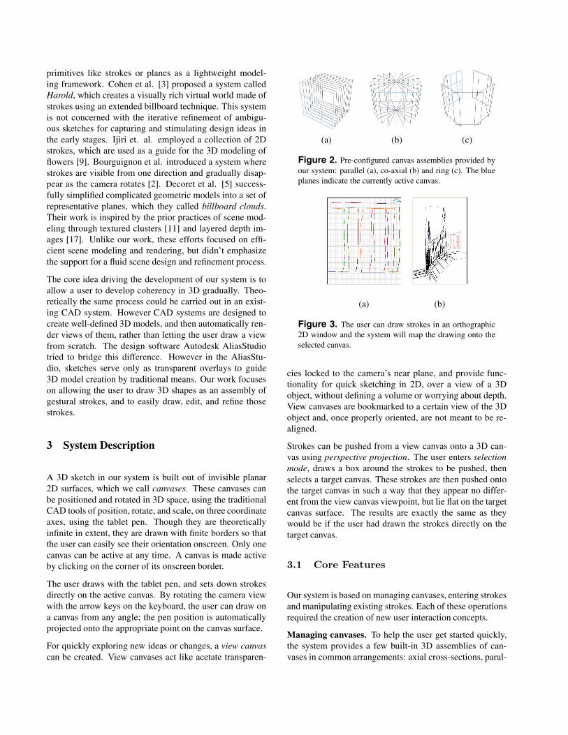
(a) (b)
Figure 4. The user can also draw directly on a canvasthrough the 3D viewport (a), and the pen position will beautomatically projected onto the canvas surface. If the can-vas is rotated or moved afterwards, the strokes will remainfixed to their relative positions on the canvas (b).
lel stacks, and a circumferential ring. (See Fig. 2.) Theseare meant as initial layouts; users can manipulate the po-sition and rotation of each canvas with a full suite of toolsvery similar to traditional CAD programs. For example, theuser can move canvases along their local coordinate axes,optionally using a single-axis constraint along any of thethree coordinate axes. To rotate an individual canvas, theuser uses the up/down/left/right arrow keys.
A problem in managing large numbers of overlapping 3Dcanvases on a 2D screen is selecting the canvas that shouldbe currently active. Conventional drawing systems use asystem of cycling through all possible 3D objects corre-sponding to a 2D screen location clicked by the user. Thiswould be impractical and frustrating in our system. Instead,we use the novel technique of selecting an active canvas byclicking near one of the corners of the rectangular icon thatrepresents the position and orientation of the infinite canvas.
Entering strokes. The user can draw strokes in three ways:on a canvas through a gridded 2D interface (Fig. 3), on acanvas in 3D (Fig. 4), and on a view canvas in 2D (Fig. 5).The 2D interface is best suited for orthogonal drawing ortracing images: the user draws lines in a gridded window,and strokes appear in the corresponding point on the 3Dcanvas. Alternatively, the user can draw directly on the 3Dcanvas, and the transformation to 2D is computed internally.The user can use existing strokes as context, and use hisnatural sense of perspective to draw how he thinks the objectshould look. These lines exist in 3D and, once drawn, canbe rotated and repositioned relative to the other canvases.If strokes are drawn outside the displayed boundaries of acanvas, the canvas icon can be expanded to include the newstrokes.
Thirdly, the user may draw strokes on a view canvas. Theview canvas is a novel representation that allows the user toorient a drawing with respect to a scene without designating
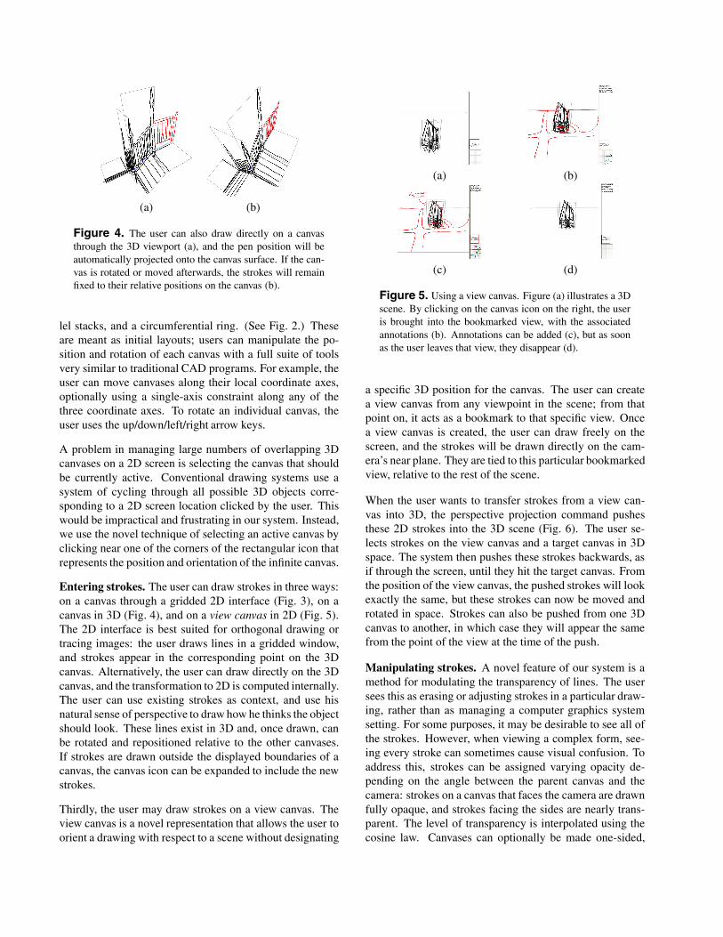
(a) (b)
(c) (d)
Figure 5. Using a view canvas. Figure (a) illustrates a 3Dscene. By clicking on the canvas icon on the right, the useris brought into the bookmarked view, with the associatedannotations (b). Annotations can be added (c), but as soonas the user leaves that view, they disappear (d).
a specific 3D position for the canvas. The user can createa view canvas from any viewpoint in the scene; from thatpoint on, it acts as a bookmark to that specific view. Oncea view canvas is created, the user can draw freely on thescreen, and the strokes will be drawn directly on the cam-era’s near plane. They are tied to this particular bookmarkedview, relative to the rest of the scene.
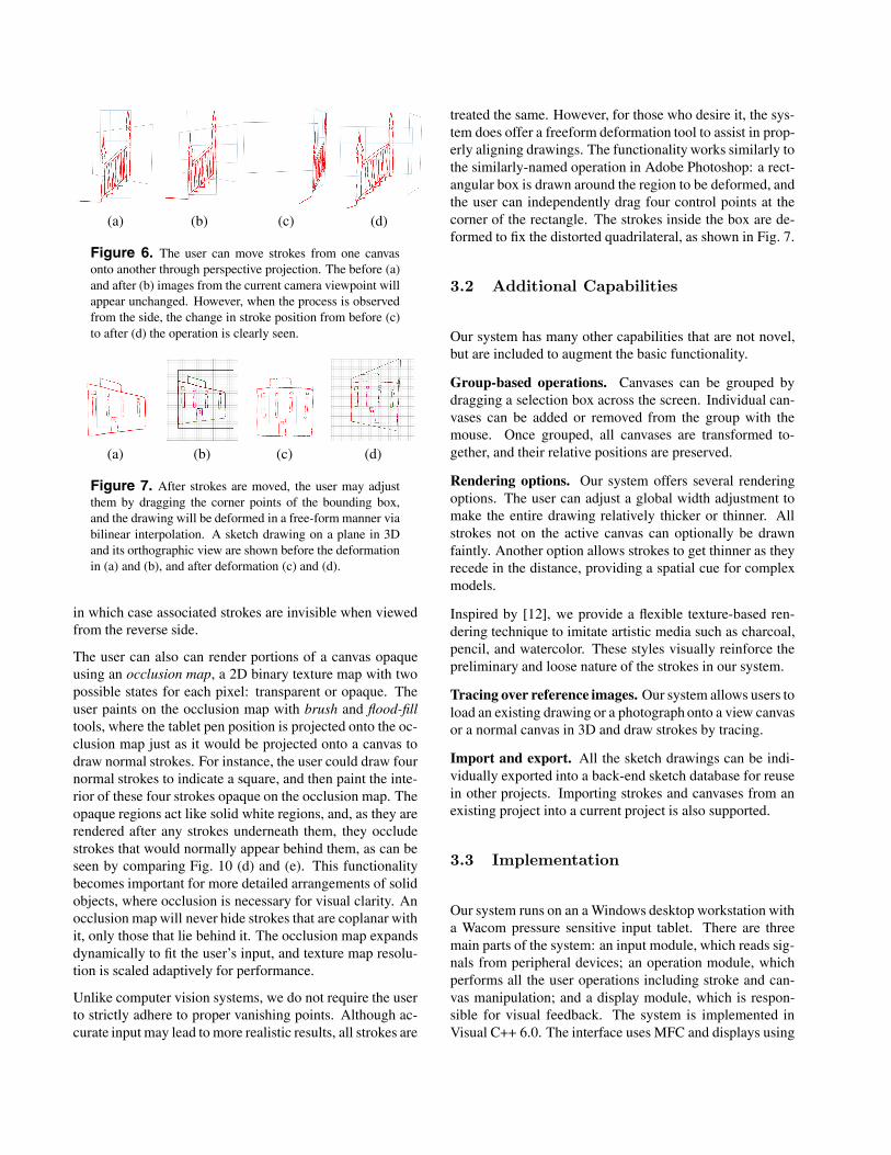
When the user wants to transfer strokes from a view can-vas into 3D, the perspective projection command pushesthese 2D strokes into the 3D scene (Fig. 6). The user se-lects strokes on the view canvas and a target canvas in 3Dspace. The system then pushes these strokes backwards, asif through the screen, until they hit the target canvas. Fromthe position of the view canvas, the pushed strokes will lookexactly the same, but these strokes can now be moved androtated in space. Strokes can also be pushed from one 3Dcanvas to another, in which case they will appear the samefrom the point of the view at the time of the push.
Manipulating strokes. A novel feature of our system is amethod for modulating the transparency of lines. The usersees this as erasing or adjusting strokes in a particular draw-ing, rather than as managing a computer graphics systemsetting. For some purposes, it may be desirable to see all ofthe strokes. However, when viewing a complex form, see-ing every stroke can sometimes cause visual confusion. Toaddress this, strokes can be assigned varying opacity de-pending on the angle between the parent canvas and thecamera: strokes on a canvas that faces the camera are drawnfully opaque, and strokes facing the sides are nearly trans-parent. The level of transparency is interpolated using thecosine law. Canvases can optionally be made one-sided,
(a) (b) (c) (d)
Figure 6. The user can move strokes from one canvasonto another through perspective projection. The before (a)and after (b) images from the current camera viewpoint willappear unchanged. However, when the process is observedfrom the side, the change in stroke position from before (c)to after (d) the operation is clearly seen.
(a) (b) (c) (d)
Figure 7. After strokes are moved, the user may adjustthem by dragging the corner points of the bounding box,and the drawing will be deformed in a free-form manner viabilinear interpolation. A sketch drawing on a plane in 3Dand its orthographic view are shown before the deformationin (a) and (b), and after deformation (c) and (d).
in which case associated strokes are invisible when viewedfrom the reverse side.
The user can also can render portions of a canvas opaqueusing an occlusion map, a 2D binary texture map with twopossible states for each pixel: transparent or opaque. Theuser paints on the occlusion map with brush and flood-filltools, where the tablet pen position is projected onto the oc-clusion map just as it would be projected onto a canvas todraw normal strokes. For instance, the user could draw fournormal strokes to indicate a square, and then paint the inte-rior of these four strokes opaque on the occlusion map. Theopaque regions act like solid white regions, and, as they arerendered after any strokes underneath them, they occludestrokes that would normally appear behind them, as can beseen by comparing Fig. 10 (d) and (e). This functionalitybecomes important for more detailed arrangements of solidobjects, where occlusion is necessary for visual clarity. Anocclusion map will never hide strokes that are coplanar withit, only those that lie behind it. The occlusion map expandsdynamically to fit the user’s input, and texture map resolu-tion is scaled adaptively for performance.
Unlike computer vision systems, we do not require the userto strictly adhere to proper vanishing points. Although ac-curate input may lead to more realistic results, all strokes are
treated the same. However, for those who desire it, the sys-tem does offer a freeform deformation tool to assist in prop-erly aligning drawings. The functionality works similarly tothe similarly-named operation in Adobe Photoshop: a rect-angular box is drawn around the region to be deformed, andthe user can independently drag four control points at thecorner of the rectangle. The strokes inside the box are de-formed to fix the distorted quadrilateral, as shown in Fig. 7.
3.2 Additional Capabilities
Our system has many other capabilities that are not novel,but are included to augment the basic functionality.
Group-based operations. Canvases can be grouped bydragging a selection box across the screen. Individual can-vases can be added or removed from the group with themouse. Once grouped, all canvases are transformed to-gether, and their relative positions are preserved.
Rendering options. Our system offers several renderingoptions. The user can adjust a global width adjustment tomake the entire drawing relatively thicker or thinner. Allstrokes not on the active canvas can optionally be drawnfaintly. Another option allows strokes to get thinner as theyrecede in the distance, providing a spatial cue for complexmodels.
Inspired by [12], we provide a flexible texture-based ren-dering technique to imitate artistic media such as charcoal,pencil, and watercolor. These styles visually reinforce thepreliminary and loose nature of the strokes in our system.
Tracing over reference images. Our system allows users toload an existing drawing or a photograph onto a view canvasor a normal canvas in 3D and draw strokes by tracing.
Import and export. All the sketch drawings can be indi-vidually exported into a back-end sketch database for reusein other projects. Importing strokes and canvases from anexisting project into a current project is also supported.
3.3 Implementation
Our system runs on an a Windows desktop workstation witha Wacom pressure sensitive input tablet. There are threemain parts of the system: an input module, which reads sig-nals from peripheral devices; an operation module, whichperforms all the user operations including stroke and can-vas manipulation; and a display module, which is respon-sible for visual feedback. The system is implemented inVisual C++ 6.0. The interface uses MFC and displays using
(a) (b) (c) (d)
(e) (f) (g) (h)
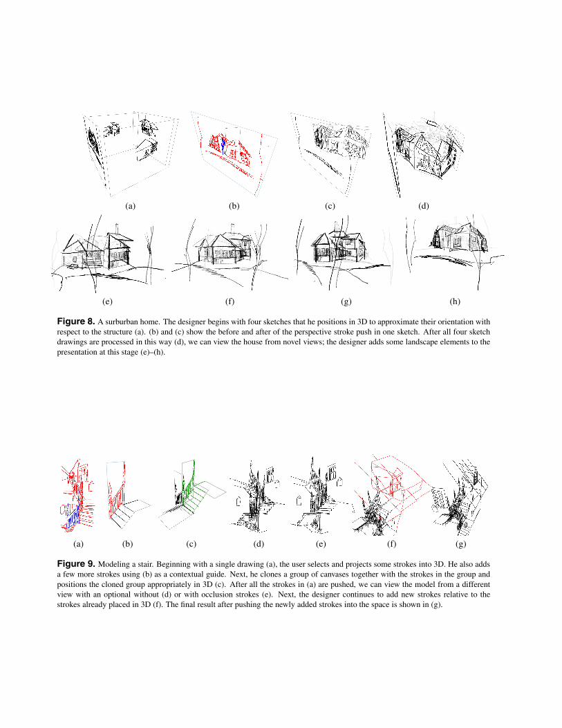
Figure 8. A surburban home. The designer begins with four sketches that he positions in 3D to approximate their orientation withrespect to the structure (a). (b) and (c) show the before and after of the perspective stroke push in one sketch. After all four sketchdrawings are processed in this way (d), we can view the house from novel views; the designer adds some landscape elements to thepresentation at this stage (e)–(h).
(a) (b) (c) (d) (e) (f) (g)
Figure 9. Modeling a stair. Beginning with a single drawing (a), the user selects and projects some strokes into 3D. He also addsa few more strokes using (b) as a contextual guide. Next, he clones a group of canvases together with the strokes in the group andpositions the cloned group appropriately in 3D (c). After all the strokes in (a) are pushed, we can view the model from a differentview with an optional without (d) or with occlusion strokes (e). Next, the designer continues to add new strokes relative to thestrokes already placed in 3D (f). The final result after pushing the newly added strokes into the space is shown in (g).
OpenGL. Strokes are captured from the pen system and rep-resented internally as a list of 3D points with an accompany-ing list of pressure values if the tablet pen is used. Canvasesare represented by their normals, and optional parameters,such as one-sidedness. For performance purposes, the list of3D points for each stroke is stored internally with the trans-formation from canvas coordinates to world coordinates al-ready applied.
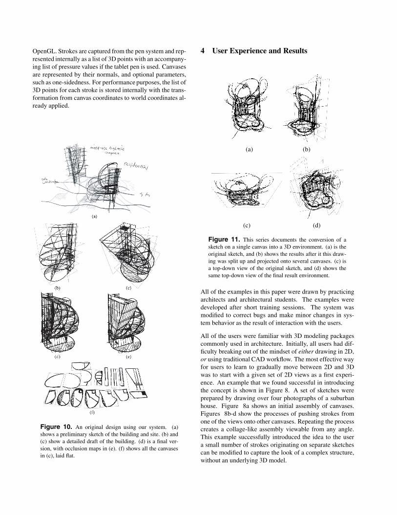
Figure 10. An original design using our system. (a)shows a preliminary sketch of the building and site. (b) and(c) show a detailed draft of the building. (d) is a final ver-sion, with occlusion maps in (e). (f) shows all the canvasesin (c), laid flat.
4 User Experience and Results
(a) (b)
(c) (d)
Figure 11. This series documents the conversion of asketch on a single canvas into a 3D environment. (a) is theoriginal sketch, and (b) shows the results after it this draw-ing was split up and projected onto several canvases. (c) isa top-down view of the original sketch, and (d) shows thesame top-down view of the final result environment.
All of the examples in this paper were drawn by practicingarchitects and architectural students. The examples weredeveloped after short training sessions. The system wasmodified to correct bugs and make minor changes in sys-tem behavior as the result of interaction with the users.
All of the users were familiar with 3D modeling packagescommonly used in architecture. Initially, all users had dif-ficulty breaking out of the mindset of either drawing in 2D,or using traditional CAD workflow. The most effective wayfor users to learn to gradually move between 2D and 3Dwas to start with a given set of 2D views as a first experi-ence. An example that we found successful in introducingthe concept is shown in Figure 8. A set of sketches wereprepared by drawing over four photographs of a suburbanhouse. Figure 8a shows an initial assembly of canvases.Figures 8b-d show the processes of pushing strokes fromone of the views onto other canvases. Repeating the processcreates a collage-like assembly viewable from any angle.This example successfully introduced the idea to the usera small number of strokes originating on separate sketchescan be modified to capture the look of a complex structure,without an underlying 3D model.
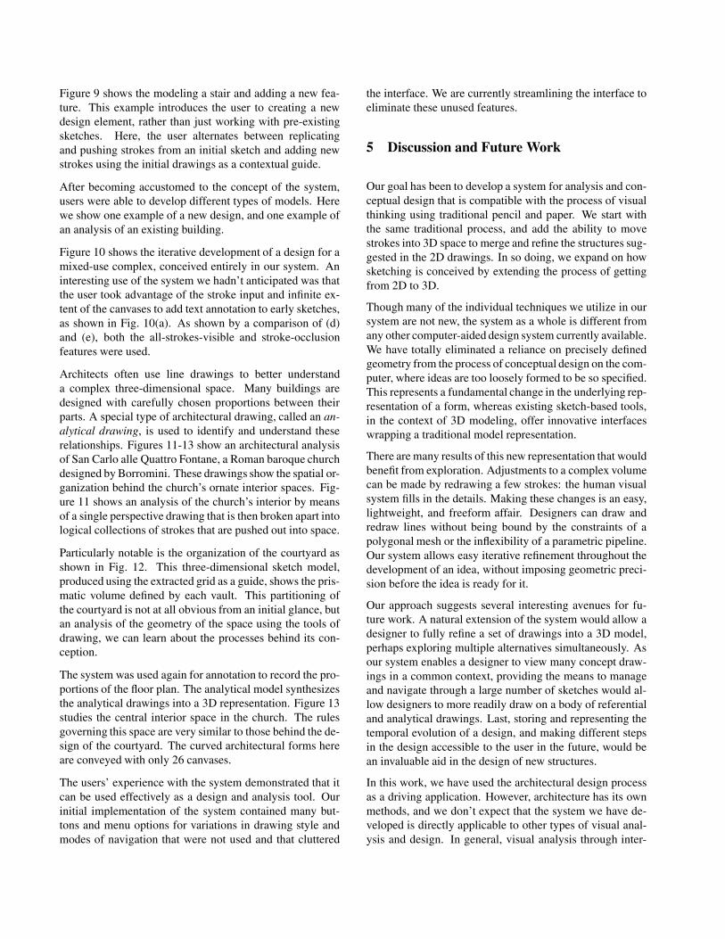
Figure 9 shows the modeling a stair and adding a new fea-ture. This example introduces the user to creating a newdesign element, rather than just working with pre-existingsketches. Here, the user alternates between replicatingand pushing strokes from an initial sketch and adding newstrokes using the initial drawings as a contextual guide.
After becoming accustomed to the concept of the system,users were able to develop different types of models. Herewe show one example of a new design, and one example ofan analysis of an existing building.
Figure 10 shows the iterative development of a design for amixed-use complex, conceived entirely in our system. Aninteresting use of the system we hadn’t anticipated was thatthe user took advantage of the stroke input and infinite ex-tent of the canvases to add text annotation to early sketches,as shown in Fig. 10(a). As shown by a comparison of (d)and (e), both the all-strokes-visible and stroke-occlusionfeatures were used.
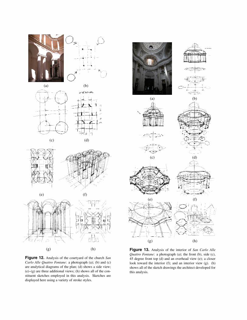
Architects often use line drawings to better understanda complex three-dimensional space. Many buildings aredesigned with carefully chosen proportions between theirparts. A special type of architectural drawing, called an an-alytical drawing, is used to identify and understand theserelationships. Figures 11-13 show an architectural analysisof San Carlo alle Quattro Fontane, a Roman baroque churchdesigned by Borromini. These drawings show the spatial or-ganization behind the church’s ornate interior spaces. Fig-ure 11 shows an analysis of the church’s interior by meansof a single perspective drawing that is then broken apart intological collections of strokes that are pushed out into space.
Particularly notable is the organization of the courtyard asshown in Fig. 12. This three-dimensional sketch model,produced using the extracted grid as a guide, shows the pris-matic volume defined by each vault. This partitioning ofthe courtyard is not at all obvious from an initial glance, butan analysis of the geometry of the space using the tools ofdrawing, we can learn about the processes behind its con-ception.
The system was used again for annotation to record the pro-portions of the floor plan. The analytical model synthesizesthe analytical drawings into a 3D representation. Figure 13studies the central interior space in the church. The rulesgoverning this space are very similar to those behind the de-sign of the courtyard. The curved architectural forms hereare conveyed with only 26 canvases.
The users’ experience with the system demonstrated that itcan be used effectively as a design and analysis tool. Ourinitial implementation of the system contained many but-tons and menu options for variations in drawing style andmodes of navigation that were not used and that cluttered
the interface. We are currently streamlining the interface toeliminate these unused features.
5 Discussion and Future Work
Our goal has been to develop a system for analysis and con-ceptual design that is compatible with the process of visualthinking using traditional pencil and paper. We start withthe same traditional process, and add the ability to movestrokes into 3D space to merge and refine the structures sug-gested in the 2D drawings. In so doing, we expand on howsketching is conceived by extending the process of gettingfrom 2D to 3D.
Though many of the individual techniques we utilize in oursystem are not new, the system as a whole is different fromany other computer-aided design system currently available.We have totally eliminated a reliance on precisely definedgeometry from the process of conceptual design on the com-puter, where ideas are too loosely formed to be so specified.This represents a fundamental change in the underlying rep-resentation of a form, whereas existing sketch-based tools,in the context of 3D modeling, offer innovative interfaceswrapping a traditional model representation.
There are many results of this new representation that wouldbenefit from exploration. Adjustments to a complex volumecan be made by redrawing a few strokes: the human visualsystem fills in the details. Making these changes is an easy,lightweight, and freeform affair. Designers can draw andredraw lines without being bound by the constraints of apolygonal mesh or the inflexibility of a parametric pipeline.Our system allows easy iterative refinement throughout thedevelopment of an idea, without imposing geometric preci-sion before the idea is ready for it.
Our approach suggests several interesting avenues for fu-ture work. A natural extension of the system would allow adesigner to fully refine a set of drawings into a 3D model,perhaps exploring multiple alternatives simultaneously. Asour system enables a designer to view many concept draw-ings in a common context, providing the means to manageand navigate through a large number of sketches would al-low designers to more readily draw on a body of referentialand analytical drawings. Last, storing and representing thetemporal evolution of a design, and making different stepsin the design accessible to the user in the future, would bean invaluable aid in the design of new structures.
In this work, we have used the architectural design processas a driving application. However, architecture has its ownmethods, and we don’t expect that the system we have de-veloped is directly applicable to other types of visual anal-ysis and design. In general, visual analysis through inter-
active drawing is in a very early stage in graphics research.Much more work remains to be done to understand visualanalysis across many creative fields to understand the rolethat graphics can play.
6 Acknowledgments
We would like to thank Phillip Isola for helpful discussionsand Soo-Hyun Kim for experimenting with the system anddeveloping the examples shown in Figures 8, 10, and 11-13.This system builds on preliminary ideas outlined in a PhDthesis authored by John Alex [1], which was supervised bythe first author. This work was supported by NSF awardCCF-0738472 and a grant from Google.
References
[1] J. P. Alex. Hybrid Sketching: A New Middle Ground Be-tween 2- and 3-D. PhD thesis, Massachusetts Institute ofTechnology, Cambridge, MA, 2005.
[2] D. Bourguignon, M.-P. Cani, and G. Drettakis. Drawing forillustration and annotation in 3D. In Computer GraphicsForum (Proc. of Eurographics), volume 20, pages 114–122,2001.
[3] J. M. Cohen, J. F. Hughes, and R. C. Zeleznik. Harold: aworld made of drawings. In Proc. of the symposium on non-photorealistic animation and rendering (NPAR), pages 83–90, 2000.
[4] J. M. Cohen, L. Markosian, R. C. Zeleznik, J. F. Hughes, andR. Barzel. An interface for sketching 3D curves. In Proc.of the symposium on Interactive 3D graphics (SI3D), pages17–21, 1999.
[5] X. Decoret, F. Durand, F. X. Sillion, and J. Dorsey. Bill-board clouds for extreme model simplification. ACM Trans.Graph., 22(3):689–696, 2003.
[6] A. Hertzmann. Tutorial: A survey of stroke-based rendering.IEEE Comput. Graph. Appl., 23(4):70–81, 2003.
[7] T. Igarashi and J. F. Hughes. A suggestive interface for 3Ddrawing. In Proc. of the symposium on user interface soft-ware and technology (UIST), pages 173–181, 2001.
[8] T. Igarashi, S. Matsuoka, and H. Tanaka. Teddy: a sketchinginterface for 3D freeform design. In SIGGRAPH ’99, pages409–416, 1999.
[9] T. Ijiri, S. Owada, and T. Igarashi. Seamless integrationof initial sketching and subsequent detail editing in flowermodeling. In Proc. of Eurographics, pages 617–624, 2006.
[10] K. Kallio. 3D6B editor: projective 3D sketching withline-based rendering. Proc. of Eurographics Workshop onSketch-based Interfaces and Modeling, pages 73–79, 2005.
[11] P. W. C. Maciel and P. Shirley. Visual navigation of largeenvironments using textured clusters. In Proc. of the Sym-posium on Interactive 3D graphics (SI3D), pages 95–103,1995.
[12] J. D. Northrup and L. Markosian. Artistic silhouettes:a hybrid approach. In Proc. of the symposium on Non-photorealistic animation and rendering (NPAR), pages 31–37, 2000.
[13] M. A. Piccolotto. Sketchpad+ architectural modelingthrough perspective sketching on a pen-based display. Mas-ter’s thesis, Cornell University, 1998.
[14] E. Sachs, A. Roberts, and D. Stoops. 3-draw: A tool for de-signing 3D shapes. IEEE Comput. Graph. Appl., 11(6):18–26, 1991.
[15] M. P. Salisbury, S. E. Anderson, R. Barzel, and D. H.Salesin. Interactive pen-and-ink illustration. In SIGGRAPH’94, pages 101–108, 1994.
[16] M. P. Salisbury, M. T. Wong, J. F. Hughes, and D. H. Salesin.Orientable textures for image-based pen-and-ink illustra-tion. In SIGGRAPH ’97, pages 401–406, 1997.
[17] J. Shade, S. Gortler, L. wei He, and R. Szeliski. Layereddepth images. In SIGGRAPH ’98, pages 231–242, 1998.
[18] I. E. Sutherland. Sketchpad: A Man-Machine GraphicalCommunication System. New York: Garland Publishers,1980.
[19] O. Tolba, J. Dorsey, and L. McMillan. Sketching with pro-jective 2D strokes. In Proc. of the symposium on user inter-face software and technology (UIST), pages 149–157, 1999.
[20] O. Tolba, J. Dorsey, and L. McMillan. A projective drawingsystem. In Proc. of Symposium on Interactive 3D graphics(SI3D), pages 25–34, 2001.
[21] S. Tsang, R. Balakrishnan, K. Singh, and A. Ranjan. A sug-gestive interface for image guided 3D sketching. In Proc.of the SIGCHI conference on Human factors in computingsystems (CHI), pages 591–598, 2004.
[22] G. Winkenbach and D. H. Salesin. Computer-generatedpen-and-ink illustration. In SIGGRAPH ’94, pages 91–100,1994.
[23] R. C. Zeleznik, K. P. Herndon, and J. F. Hughes. Sketch: aninterface for sketching 3D scenes. In SIGGRAPH ’96, pages163–170, 1996.
(a) (b)
(c) (d)
(e) (f)
(g) (h)
Figure 12. Analysis of the courtyard of the church SanCarlo Alle Quattro Fontane: a photograph (a); (b) and (c)are analytical diagrams of the plan; (d) shows a side view;(e)–(g) are three additional views; (h) shows all of the con-stituent sketches employed in this analysis. Sketches aredisplayed here using a variety of stroke styles.
(a) (b)
(c) (d)
(e) (f)
(g) (h)
Figure 13. Analysis of the interior of San Carlo AlleQuattro Fontane: a photograph (a); the front (b), side (c),45 degree front top (d) and an overhead view (e); a closerlook toward the interior (f); and an interior view (g). (h)shows all of the sketch drawings the architect developed forthis analysis.