computers and electrical engineeringoptcom/publications/omcl-mod-cee-14.pdf · a survey on recent...
TRANSCRIPT

Computers and Electrical Engineering 40 (2014) 216–240
Contents lists available at ScienceDirect
Computers and Electrical Engineering
journal homepage: www.elsevier .com/ locate /compeleceng
A survey on recent advances in optical communications q
0045-7906/$ - see front matter � 2013 Elsevier Ltd. All rights reserved.http://dx.doi.org/10.1016/j.compeleceng.2013.11.017
q Reviews processed and approved for publication by Editor-in-Chief Dr. Manu Malek.⇑ Corresponding author. Tel.: +1 4342276165.
E-mail addresses: [email protected] (J. He), [email protected] (R.A. Norwood), [email protected] (M. Brandt-Pearce), ivanarizona.edu (I.B. Djordjevic), [email protected] (M. Cvijetic), [email protected] (S. Subramaniam), [email protected] (R. [email protected] (C. Reynolds), [email protected] (P. Blanche), [email protected] (B. Lynn), [email protected](N. Peyghambarian).
Jun He a,⇑, Robert A. Norwood a, Maïté Brandt-Pearce b, Ivan B. Djordjevic c, Milorad Cvijetic a,Suresh Subramaniam d, Roland Himmelhuber a, Carolyn Reynolds a, Pierre Blanche a,Brittany Lynn a, Nasser Peyghambarian a
a College of Optical Sciences, University of Arizona, United Statesb Charles L. Brown Department of Electrical and Computer Engineering, University of Virginia, United Statesc Department of Electrical and Computer Engineering, University of Arizona, United Statesd Department of Electrical and Computer Engineering, George Washington University, United States
a r t i c l e i n f o a b s t r a c t
Article history:Available online 12 December 2013
Recent advances in optical communications not only increase the capacities of communi-cation system but also improve the system dynamicity and survivability. Various new tech-nologies are invented to increase the bandwidth of individual wavelength channels and thenumber of wavelengths transmitted per fiber. Multiple access technologies have also beendeveloped to support various emerging applications, including real-time, on-demand andhigh data-rate applications, in a flexible, cost effective and energy efficient manner.
In this paper, we overview recent research in optical communications and focus on thetopics of modulation, switching, add-drop multiplexer, coding schemes, detection schemes,orthogonal frequency-division multiplexing, system analysis, cross-layer design, controland management, free space optics, and optics in data center networks. The primarypurpose of this paper is to refresh the knowledge and broaden the understanding ofadvances in optical communications, and to encourage further research in this area andthe deployment of new technologies in production networks.
� 2013 Elsevier Ltd. All rights reserved.
1. Introduction
In the past decade, emerging applications such as delay sensitive network applications (e.g. telepresence and online real-time gaming) and high throughput network applications (e.g. e-science, cloud service, and high definition video streaming ser-vices), take up a major portion of the network bandwidth in today’s networks. Driven by the dramatically increasing throughputdemand and quality of service requirement, optical communication systems are needed not only in transport backbone net-works but also in metropolitan area and access networks. Motivated by these calls, researchers have developed or improvedoptical signal processing functions (e.g., amplification, filtering, and dispersion compensation) to satisfy optical communicationrequirements. To further improve the communication system performance, researchers have built new optical network systemarchitecture, proposed efficient algorithmic and systematic design, and created dynamic and intelligent optical networks.
This paper presents the current state of the art for optical communications and network systems. The focus is opticalcommunication components, subsystem, and systems and networking technologies. Several new emerging topics, such as
@email.elhuber),zona.edu
J. He et al. / Computers and Electrical Engineering 40 (2014) 216–240 217
using optics in data center networks, will also be covered. The remainder of the paper is organized as follows. Section 2 intro-duces the recent advances in optical components, including modulators, switches, and reconfigurable components. In Sec-tion 3, we describe the state of the art signal processing technologies in optical fiber communications. The recentadvances in optical fiber communication systems and networking is described in Section 4. Additionally, the state of theart for free space optical communications is presented in Section 5. Several emerging technologies are presented in Section 6.Conclusions are drawn in Section 7.
2. Recent advances in optical components
2.1. Optical modulators
External optical modulators are used extensively in optical communications, especially in dense wavelength divisionmultiplexing systems where the narrow linewidth requirements of the laser make direct modulation impractical, owingto the accompanying laser chirp. There has been an increasing drive towards the integration of lasers with modulators,which can be monolithically achieved in III–V semiconductors that can be used to make both the laser and an electro-absorption modulator. This has been demonstrated at its highest level by companies like Infinera, who have placed arraysof WDM transmitters on a single indium phosphide chip [1]. Electro-absorption modulators are based upon the quantumconfined Stark effect and the Burstein–Moss shift in multiple quantum well semiconductors; they suffer from relativelylow contrast and nonlinearities, but perform well for short to moderate reach applications and have the benefit of low powerconsumption and footprint. The same can be said of silicon modulators that are based on free-carrier absorption; thesedevices are, however, even less efficient than EAMs based on III–V semiconductors. Lithium niobate has long been the goldstandard for external optical modulation, and this is the still the case as lithium niobate modulators with both lowerinsertion loss and half-wave voltage continue to be produced. With the adoption of coherent communications, the highestserial rate currently used for external modulators is predominantly 25 Gbps, which is still well within lithium niobate’s capa-bilities, especially when clever engineering can be applied to achieving velocity matching for the electrical and optical waves.
For much higher bit rates (40 Gbps and above) lithium niobate is no longer a viable material for electro-optic modulation,but in this range electro-optic polymer modulators have been demonstrated up to 160 Gbps. DeRose et al. [2] shows an elec-tro-optic polymer/sol–gel modulator developed by the University of Arizona, which achieved commercially competitive per-formance with respect to insertion loss (5.7 dB) and drive voltage (2.8 V), while having the intrinsically high bandwidth of EOpolymer modulators. While the high speed capabilities of electro-optic polymers have long been understood, owing to thepractical equivalence of the optical refractive index with the square root of the microwave dielectric constant, a major devel-opment is the availability of Telcordia qualified 40 Gbps and 100 Gbps EO polymer modulators with <5 V drive voltage fromGigOptix [3]. This technology stands poised to address the next generation of data rates and, furthermore, may see earlyapplication within large data centers, where rack to rack communication is already occurring at 40 Gbps.
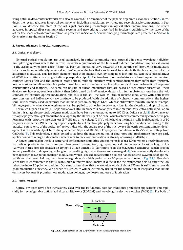
A longer term goal in the data center and performance computing environments is to use EO polymers directly integratedwith silicon photonics to realize compact, low power consumption, high speed optical interconnects of various lengths. Ini-tial work in this area has focused on trying to utilize difficult-to-fabricate silicon slot waveguide structures, which providefor very small electrode spacing, as long as the resulting high capacitance can be managed [4]. We have recently developed anew approach to EO polymer/silicon modulators which is based on fabricating a silicon nanowire strip waveguide of optimalwidth and then overcladding the silicon waveguide with a high performance EO polymer as shown in Fig. 2.1.1. One chal-lenge that is encountered is that silicon’s high refractive index makes it difficult for the evanescent field to enter the lowrefractive index EO polymer cladding. Our simulations show that a waveguide width of about 275 nm is sufficient to providegood modulation efficiency. We believe this structure will be extremely useful for the realization of integrated modulatorson silicon, because it promises low modulation voltages, low losses and ease of fabrication.
2.2. Optical switches
Optical switches have been increasingly used over the last decade, both for traditional protection applications and espe-cially for reconfigurable optical add drop multiplexers (ROADM) and wavelength selective switches (WSS) [5]. For both of
Fig. 2.1.1. Cross-section of the EO polymer/silicon nanostrip phase modulator.
218 J. He et al. / Computers and Electrical Engineering 40 (2014) 216–240
these applications a broad range of technologies are available that can meet the requirements, since the switching speed re-quired is on the order of a millisecond. Liquid crystals, digital micromirror devices (DMD) [6], and thermo-optic silica orpolymer waveguide switches are capable of this speed and all of have been used for both ROADM and WSS applications.For high port count switching with low insertion loss and low crosstalk, DMDs have increasingly been the preferred solution,although liquid crystal on silicon (LCOS) [7] has advantages in terms of compactness and power consumption, while wave-guide switches can be directly integrated with waveguide filter technology such as arrayed waveguide gratings (AWG).State-of-the-art heterogeneous aggregation optical systems use low port count high speed switches, based on semiconductoroptical amplifier (SOA) technology, for nanosecond solid-state switching, and the future may see the use of electro-optictechnologies such as lithium niobate and electro-optic polymers for true packet switching.
In current optical networks, every switching node converts optical signals to electrical form (O/E conversion), buffers andprocesses the signals electronically, and then converts them back to optical form again (E/O conversion). As the network capac-ity increases at an unprecedented rate, electronic switching nodes will not be able to keep up. Electronic signals are stronglydependent on data rate and protocol, thus deficient for next generation requirements. Therein lies the need to eliminate O/E/O converters and upgrade to all optical networks (O–O). By doing so, optical switches will replace electronic switches and reducenetwork equipment, increase current switching speeds, decrease operating power, and decrease overall system cost.
Optical switches are devices that can direct input signals to the appropriate output port without requiring O/E/O conver-sions. Optical switches offer significant advantages: transparency to bit rate and data protocol; scalability to large portcounts; and reduction in cost, size and complexity [8]. Yet at the same time, when signals remain entirely in the optical do-main, certain challenges arise: lack of bit memory and bit processing; and no signal regeneration with retiming and shaping.
There are various types of optical switches available within today’s market. Among the choices, one type of optical switchtechnology may be preferred over another depending on the application of interest. A listing of eight different types is givenbelow [8].
1. Opto-mechanical-switching performed by prisms, moving fibers, and mirrors (mechanical means). These switches offerlow insertion losses, polarization dependent loss, crosstalk, power consumption and fabrication costs. Their switchingspeeds are on the order of a few milliseconds.
2. Optical MEMS-switching performed by mechanical, optical and electronic means. Of MEMS switches, there are 2D (dig-ital) and 3D (analog) approaches. 2D MEMS switches are bistable (either on or off), allowing the reflected beam to remainin the same plane as the incident beam. For 3D MEMS switches there are at least 2 mirrors for the reflection of the incom-ing beam to a specified output port. 3D MEMS switches offer the capability to make large switches on the order of 1000input and output ports.
3. Electro-optic-switching performed by applying a voltage to the substrate, thus changing the substrate’s index of refrac-tion. In changing the index of refraction, the light is manipulated to travel to the desired output port, usually through theuse of optical waveguide structures such as directional couplers or Mach–Zehnder interferometers. The switching timefor this device is less than a nanosecond and is very reliable.
4. Thermo-optic-switching performed by varying a material’s temperature. In changing the temperature, the index of refrac-tion changes; again redirecting the light to the desired output port, again usually employing a waveguide geometry. Inthese devices heat is delivered locally by sending current through lithographically patterned electrodes. The switchingtime is on the order of a millisecond.
5. Liquid crystal-switching performed by applying an electric field to re-orientate liquid crystal molecules within a material.In doing so, polarization of the incident beam is changed. The output beam passes through a polarization beam splitterand directed to a specified port [8]. The switching time for this device is in the range from microseconds to milliseconds,depending on the type of liquid crystal used.
6. Bubble-switching performed by heating and cooling of a substrate containing a liquid. When heated, bubbles form. Thetiny bubbles deflect light to output ports. Switching time is on the order of milliseconds.
7. Acousto-optic-switching performed by the interaction of light and sound. The incident light is split into its 2 orthogonallypolarized components (TE & TM). A formed sound wave travels in the same direction as the polarized light acting as amoving grating. This interaction causes the light components to interchange from TM to TE and vice versa. The switchingspeed is on the order of nanoseconds to microseconds.
8. Semiconductor optical amplifier (SOA)-switching performed by applying a voltage to amplify light and thereby achieve anon–off functionality; space switching can be achieved by selectively amplifying a single waveguide emerging from a split-ter, for example. The switching speed is on the order of a nanosecond.
Optical switches are currently used to reconfigure/restore the network and increase its reliability; future networks mayeventually use optical packet switching. A successful optical switch has to demonstrate superiority in the areas of insertionloss, switching time, port count, cross talk, extinction ratio, polarization dependent loss, reliability, scalability, repeatability,power consumption, ease of fabrication, and multicast capability.
2.2.1. Diffractive DMD switchA novel new switching approach has been developed with the potential for manufacturing a high port count, fast, low
insertion loss optical switch based on using the proven Texas Instruments digital micro-mirrors device (DMD) in a diffractive

J. He et al. / Computers and Electrical Engineering 40 (2014) 216–240 219
mode [6]. The advantages of this technology include fast reconfiguration time (50 ls), latching, and low power consumption.Existing high volume opto-electronics manufacturing process will provide large advantages in cost and reliability comparedto traditional optics.
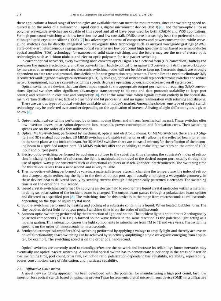
The current approach takes advantage of the DMD [8], but by using diffraction instead of reflection (Fig. 2.2.1). Here dif-fraction is defined as the change of direction of the switching light due to an aperture, such as a slit. By carefully organizingthe size and position of multiple apertures, the direction of the diffracted light can be finely tuned. Such an arrangement ofapertures is referred as a diffraction pattern, or hologram, and can be loaded as an image on the DMD. Light striking the DMDbinary hologram will be redirected according to the calculated pattern and enter the output fibers. Using a hologram, thediffracted direction is not limited to just two directions as with reflection from the DMD mirrors. This approach is trulynon-blocking, moreover, one incoming beam can be divided into different output directions, or different input beams canbe combined together at the same output location.
2.3. Reconfigurable optical add-drop multiplexer
Optical add/drop multiplexers (OADMs) are the specialized network elements for implementing add, drop, and opticalbypass functionalities at optical nodes. A reconfigurable optical add/drop multiplexer (ROADM) is more agile than an OADMand is an all-optical network element to enable software driven remote lightpath reconfiguration without on-site manualintervention. ROADMs bring several significant benefits, such as simplified planning, better bandwidth utilization, and lowerOperational Expenditure (OPEX) and Capital Expenditure (CAPEX) to network operators, and thus are widely deployed andwell entrenched in optical networks around the world [9]. Enormous research efforts focus on creating next generationROADMs with colorless, directionless, contentionless, and gridless, which give operators the ultimate level of flexibility atthe optical layer [5,7,10,11].
The key ROADM capabilities to enable dynamic all-optical networking include colorless, directionless, contentionless(CDC), and gridless functionalities [9]. The colorless feature at an add/drop port of an ROADM node refers that any wave-length can be added/dropped at any port; the directionless feature at an add/drop port refers that any channel added ona port can be directed to any outbound nodal degree, and vice versa; contentionless feature refers to allowing multiple copiesof the same wavelength on a single add/drop structure [11]. CDC ROADMs are capable of switching any wavelength from anyof input ports to any of the out ports and thus give the operators the ultimate level of flexibility at the optical layer [10].ROADM nodes are called gridless if they support a flexi grid and can operate at any speed that is based on a more granularspacing less than 50 GHz [9], and hence can greatly improve spectral efficiency [5,7]. To realize gridless feature, a key is ableto independently control the central frequency and channel bandwidth of the WSS. Optical orthogonal frequency divisionmultiplexing (O-OFDM) technology can be used to enable the ROADM to support dynamic add/drop of channels [5,7], whichis covered in Section 3.3.
Key technologies used in ROAMD include wavelength blocking, planar lightwave circuit (PLC) [12] and wavelength selec-tive switching (WSS) [5] or 2D/3D micro-electro-mechanical system (MEMS) switches. Within ROADM, WSS has a centralrole to play in ROADM networks and it can dynamically select individual wavelengths from multiple DWDM input fibersand switch these to a common output fiber in the optical domain without expensive optic-electronic (OE) conversion [9].To maximize the overall performance, Dynamic Channel Equalization (DCE) is integrated in WSS to equalize optical poweramong the wavelengths [10]. WSS elements can use 2D MEMS mega-pixel matrix switching arrays, as well as other
Fig. 2.2.1. Conceptual sketch of an optical switch using the DMD array in a diffractive mode.


J. He et al. / Computers and Electrical Engineering 40 (2014) 216–240 221
0.5 and 0.75, meaning that 2 bits are carried per symbol. In MLC, the bit streams originating from m different informationsources are encoded using different (n, ki) LDPC codes of code rate ri = ki/n. ki denotes the number of information bits ofthe ith (i = 1, 2, . . . , m) component LDPC code, and n denotes the codeword length, which is the same for all LDPC codes.The mapper accepts m bits, c = (c1, c2, . . . , cm), at time instance i from the (m � n) interleaver column-wise and determinesthe corresponding M-ary (M = 2m) constellation point si = (Ii, Qi) = |si|exp(j/i) (see Fig. 3.1.1(a)).
The exponential growth of Internet traffic places enormous demands for the transmission rate at every level, as well as ademand for energy that needs to be consumed as bandwidth grows. Therefore, system design is becoming constrained byboth information capacity and energy consumption. To address both constraints simultaneously, the signal constellationsaimed to improve spectral efficiency should be designed by also taking energy-efficiency into account. Possible approachesinclude: the use the concepts of statistical physics in signal constellation design [13], the Monte Carlo method based opti-mum signal constellation design (OSCD) [14], and Lagrangian method based signal constellation design [15]. As an illustra-tion, we will provide a description of multidimensional coded modulation scheme (CM) enabling ultrahigh-speed opticaltransport in an energy efficient manner. This scheme can also be called hybrid as it employs all available degrees of freedom[13–15]. The scheme employs in-phase/quadrature channels, two spin angular momentum (SAM) states, and N orbital angu-lar momentum (OAM) states resulting in D = 4N-dimensional signal-space. The overall system configuration is depicted inFig. 3.1.2. The D independent data streams are LDPC-encoded and codewords are written into block-interleaver row-wise.The D bits are taken from the block-interleaver column-wise and used to select a point from a 2D-ary signal constellationstored in the look-up table (LUT). The coordinates from LUT are used as inputs of the D-dimensional modulator. The D-dimensional modulator, whose configuration is shown in Fig. 3.1.2(a), generates the signal constellation points bysi ¼ CD
PDd¼1/i;dUd, where /i,d denotes the dth coordinate (d = 1, 2, . . . , D) of the ith signal-constellation point, while the
set {U1, . . . ,UD} denotes the basis functions introduced above.A CW laser diode signal in transmitter from Fig. 3.1.2(a) is split into N branches by using a power splitter to feed 4-D elec-
tro-optical modulators, each corresponding to one out of N OAM modes. The 4-D electro-optical modulator is composed of apolarization-beam splitter (PBS), two I/Q modulators, and a polarization-beam combiner (PBC). The OAM mode multiplexeris composed of N waveguides, a taper-core fiber, and FMF, properly designed to excite orthogonal OAM modes in FMF. The4N-dimensional demodulator architecture is shown in Fig. 3.1.2(b). We first perform OAM mode-demultiplexing in theOAM-demux block (see Fig. 3.1.2(b)), whose outputs are 4-D projections along N OAM states. Each OAM mode undergoespolarization-diversity coherent detection and corresponding outputs are forwarded to a 4N-dimensional a posterioriprobability (APP) demapper as shown in Fig. 3.1.2(c). In the APP demaper we first calculate symbol LLRs, which are then usedto calculate bit LLRs needed for LDPC decoding, as shown in Fig. 3.1.2(c). After LDPC decoding, extrinsic bit LLRs are used tocalculate the prior symbol LLRs for the APP demapper. The N-dimensional signal constellations obtained by either sphere-packing method or as a particular instance of EE-OSCD are studied in [14] for use in the few-mode optical fiber systemdescribed above for a symbol rate of 25 GS/s. The quasi-cyclic, girth-10, column-weight-3, LDPC (34665, 27734, 0.8) codeis used as a channel code. To precisely estimate the improvement in optical signal-to-noise ratio (OSNR) sensitivity withrespect to conventional constellations, we performed the Monte Carlo simulations. In this particular instance, coded-modulation is used in combination with polarization-division multiplexing (PDM). Orthogonal OAM modes, properly
Source channels
1
l
.
.
.
BlockInterleaver
lxn
Mapper+
symbol-levelinterleaving
l to SMF
LDPC encoder 1R1=k1/n
…
.
.
.DFB
PM
PM π/2
iI
iQ
LDPC encoder lRl=kl/n
Source channels
1
l
.
.
.
BlockInterleaver
lxn
BlockInterleaver
lxn
Mapper+
symbom l-levelinterleaving
Mapper+
symbol-levelinterleaving
l to SMF
LDPC encoder 1R1=k1/n
LDPC encoder 1R1=k1/n
…
.
.
.DFBDFB
PMPM
PMPM π/2π/2
iI
iQ
LDPC encoder lRl=kl/ll n
LDPC encoder lRl=kl/n
(a)
APP D
emapper
Bit L
LR
sC
alculation
LDPC Decoder 1
mfrom fiber
π/2
Ts
Ts
| |j i
i iE E eϕ=
*1Re i iE E −
{ }*1Im i iE E −
LDPC Decoder
.
.
.
APP D
emapper
Bit L
LR
sC
alculation
LDPC Decoder 1
mfrom fiber
π/2
Ts
Ts
| |j i
i iE E eϕ=
{ }*1Re i iE E −
*1Im i iE E −
LDPC Decoder
.
.
.
(b)
APP D
emapper
Bit L
LR
sC
alculation
LDPC Decoder 1
m
From fiber
π/2,| |j S i
i iS S eϕ
=Re *iS L
LDPC Decoder
.
.
.From local laser
| |j LL L eϕ
= Im *iS L
APP D
emapper
Bit L
LR
sC
alculation
LDPC Decoder 1
m
From fiber
π/2,| |j S i
i iS S eϕ
= { }Re *iS L
LDPC Decoder
.
.
.From local laser
| |j LL L eϕ
= { }Im *iS L
(c)
Fig. 3.1.1. Block-interleaved LDPC-coded modulation scheme: (a) transmitter architecture, (b) direct detection architecture, and (c) coherent detectionreceiver architecture. Ts = 1/Rs, Rs is the symbol rate.


6 8 10
10-9
10-8
10-7
10-6
10-5
10-4
10-3
10-2
Bit-e
rror r
atio
, BER
Q-factor, Q [dB] (per information bit)
Uncoded OOK Min-sum on FPGA Min-sum in C Min-sum-with-correction in C
0 1 2 … c-1
0 I I I … I
1 I P S[1] P S[2] … P S[c-1]
2 I P 2S[1] P 2S[2] … P 2S[c-1]
… … … … … …
r-1 I P (r-1) S[1] P (r-1) S[2] … P (r-1) S [c-1]
CPEs
BPEs
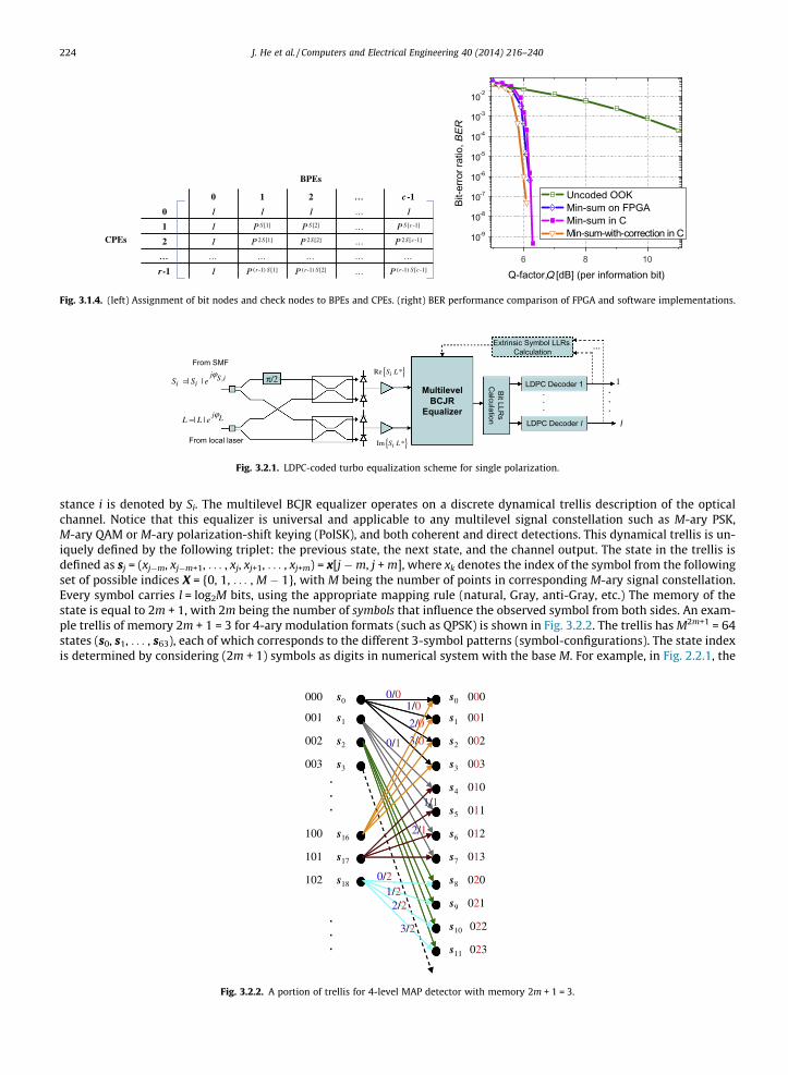
Fig. 3.1.4. (left) Assignment of bit nodes and check nodes to BPEs and CPEs. (right) BER performance comparison of FPGA and software implementations.
Bit LLRs
Calculation
LDPC Decoder 1 1
l
From SMF
π/2,| |j S i
i iS S eϕ
=Re *iS L
LDPC Decoder l
.
.
.
From local laser
| |j LL L eϕ
=
Im *iS L
MultilevelBCJR
Equalizer
Extrinsic Symbol LLRs Calculation
…
.
.
.
{ }
{ }
Fig. 3.2.1. LDPC-coded turbo equalization scheme for single polarization.
224 J. He et al. / Computers and Electrical Engineering 40 (2014) 216–240
stance i is denoted by Si. The multilevel BCJR equalizer operates on a discrete dynamical trellis description of the opticalchannel. Notice that this equalizer is universal and applicable to any multilevel signal constellation such as M-ary PSK,M-ary QAM or M-ary polarization-shift keying (PolSK), and both coherent and direct detections. This dynamical trellis is un-iquely defined by the following triplet: the previous state, the next state, and the channel output. The state in the trellis isdefined as sj = (xj�m, xj�m+1, . . . , xj, xj+1, . . . , xj+m) = x[j �m, j + m], where xk denotes the index of the symbol from the followingset of possible indices X = {0, 1, . . . , M � 1}, with M being the number of points in corresponding M-ary signal constellation.Every symbol carries l = log2M bits, using the appropriate mapping rule (natural, Gray, anti-Gray, etc.) The memory of thestate is equal to 2m + 1, with 2m being the number of symbols that influence the observed symbol from both sides. An exam-ple trellis of memory 2m + 1 = 3 for 4-ary modulation formats (such as QPSK) is shown in Fig. 3.2.2. The trellis has M2m+1 = 64states (s0, s1, . . . , s63), each of which corresponds to the different 3-symbol patterns (symbol-configurations). The state indexis determined by considering (2m + 1) symbols as digits in numerical system with the base M. For example, in Fig. 2.2.1, the
000 s0
001 s1
002 s2
003 s3
100 s16
101 s17
102 s18
s0 000
s1 001
s2 002
s3 003
s4 010
s5 011
s6 012
s7 013
s8 020
s9 021
s10 022
s11 023
0/1
1/0
2/0
3/0
.
.
.
.
.
.
0/0
2/1
1/1
0/21/2
2/2
3/2
Fig. 3.2.2. A portion of trellis for 4-level MAP detector with memory 2m + 1 = 3.
J. He et al. / Computers and Electrical Engineering 40 (2014) 216–240 225
quaternary numerical system (with the base 4) is used. The left column in dynamic trellis represents the current states andthe right column denotes the terminal states. The branches are labeled by two symbols, the input symbol is the last symbolin initial state (the blue symbol), the output symbol is the central symbol of terminal state (the red symbol). Therefore, thecurrent symbol is affected by both previous and incoming symbols. For the complete description of the dynamical trellis, thetransition probability density functions (PDFs) p(yj|xj) = p(yj|s), s e S are needed; where S is the set of states in the trellis, andyj is the vector of samples (corresponding to the transmitted symbol index xj). The conditional PDFs can be determined fromcollected histograms. The number of edges originating in any of the left-column states is M, and the number of merging edgesin arbitrary terminal state is also M. The forward metric is defined as aj (s) = log{p(sj = s, y[1, j])} (j = 1, 2, . . . , n); the backwardmetric is defined as bj(s) = log{p(y[j + 1, n]|sj = s)}; and the branch metric is defined as cj(s0, s) = log[p(sj = s, yj, sj�1 = s0)].
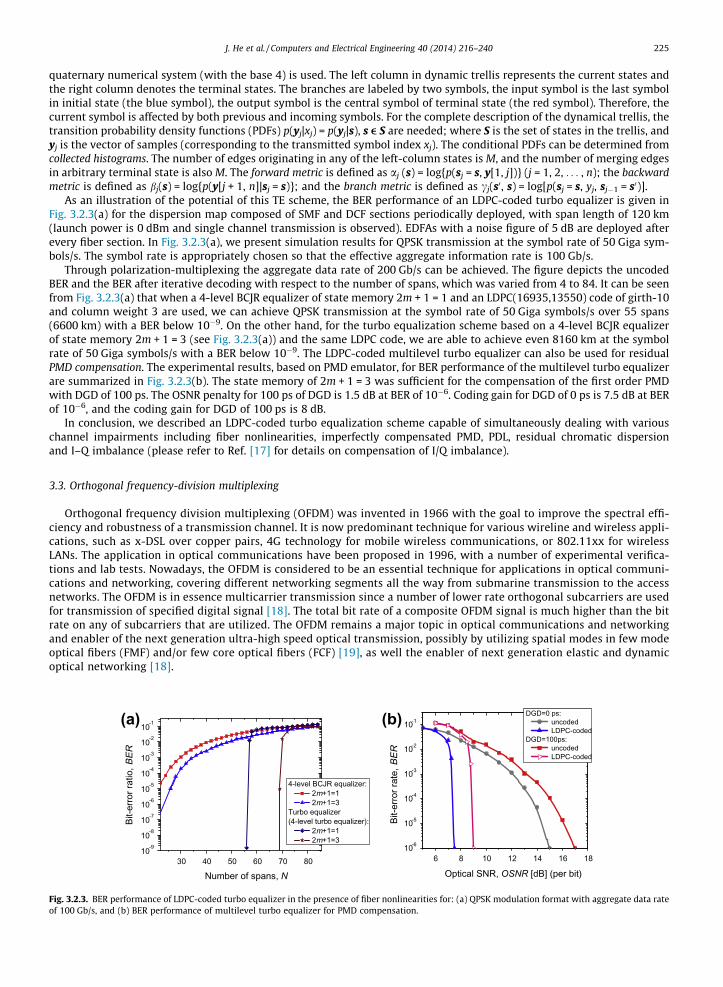
As an illustration of the potential of this TE scheme, the BER performance of an LDPC-coded turbo equalizer is given inFig. 3.2.3(a) for the dispersion map composed of SMF and DCF sections periodically deployed, with span length of 120 km(launch power is 0 dBm and single channel transmission is observed). EDFAs with a noise figure of 5 dB are deployed afterevery fiber section. In Fig. 3.2.3(a), we present simulation results for QPSK transmission at the symbol rate of 50 Giga sym-bols/s. The symbol rate is appropriately chosen so that the effective aggregate information rate is 100 Gb/s.
Through polarization-multiplexing the aggregate data rate of 200 Gb/s can be achieved. The figure depicts the uncodedBER and the BER after iterative decoding with respect to the number of spans, which was varied from 4 to 84. It can be seenfrom Fig. 3.2.3(a) that when a 4-level BCJR equalizer of state memory 2m + 1 = 1 and an LDPC(16935,13550) code of girth-10and column weight 3 are used, we can achieve QPSK transmission at the symbol rate of 50 Giga symbols/s over 55 spans(6600 km) with a BER below 10�9. On the other hand, for the turbo equalization scheme based on a 4-level BCJR equalizerof state memory 2m + 1 = 3 (see Fig. 3.2.3(a)) and the same LDPC code, we are able to achieve even 8160 km at the symbolrate of 50 Giga symbols/s with a BER below 10�9. The LDPC-coded multilevel turbo equalizer can also be used for residualPMD compensation. The experimental results, based on PMD emulator, for BER performance of the multilevel turbo equalizerare summarized in Fig. 3.2.3(b). The state memory of 2m + 1 = 3 was sufficient for the compensation of the first order PMDwith DGD of 100 ps. The OSNR penalty for 100 ps of DGD is 1.5 dB at BER of 10�6. Coding gain for DGD of 0 ps is 7.5 dB at BERof 10�6, and the coding gain for DGD of 100 ps is 8 dB.
In conclusion, we described an LDPC-coded turbo equalization scheme capable of simultaneously dealing with variouschannel impairments including fiber nonlinearities, imperfectly compensated PMD, PDL, residual chromatic dispersionand I–Q imbalance (please refer to Ref. [17] for details on compensation of I/Q imbalance).
3.3. Orthogonal frequency-division multiplexing
Orthogonal frequency division multiplexing (OFDM) was invented in 1966 with the goal to improve the spectral effi-ciency and robustness of a transmission channel. It is now predominant technique for various wireline and wireless appli-cations, such as x-DSL over copper pairs, 4G technology for mobile wireless communications, or 802.11xx for wirelessLANs. The application in optical communications have been proposed in 1996, with a number of experimental verifica-tions and lab tests. Nowadays, the OFDM is considered to be an essential technique for applications in optical communi-cations and networking, covering different networking segments all the way from submarine transmission to the accessnetworks. The OFDM is in essence multicarrier transmission since a number of lower rate orthogonal subcarriers are usedfor transmission of specified digital signal [18]. The total bit rate of a composite OFDM signal is much higher than the bitrate on any of subcarriers that are utilized. The OFDM remains a major topic in optical communications and networkingand enabler of the next generation ultra-high speed optical transmission, possibly by utilizing spatial modes in few modeoptical fibers (FMF) and/or few core optical fibers (FCF) [19], as well the enabler of next generation elastic and dynamicoptical networking [18].
30 40 50 60 70 8010-9
10-8
10-7
10-6
10-5
10-4
10-3
10-2
10-1
Bit-e
rror r
atio
, BER
Number of spans, N
4-level BCJR equalizer: 2m+1=1 2m+1=3
Turbo equalizer (4-level turbo equalizer):
2m+1=1 2m+1=3
6 8 10 12 14 16 1810-6
10-5
10-4
10-3
10-2
10-1
Bit-e
rror r
ate,
BER
Optical SNR, OSNR [dB] (per bit)
DGD=0 ps: uncoded LDPC-coded
DGD=100ps: uncoded LDPC-coded
(a) (b)
Fig. 3.2.3. BER performance of LDPC-coded turbo equalizer in the presence of fiber nonlinearities for: (a) QPSK modulation format with aggregate data rateof 100 Gb/s, and (b) BER performance of multilevel turbo equalizer for PMD compensation.

J. He et al. / Computers and Electrical Engineering 40 (2014) 216–240 227
midway between some subcarriers and multiple subcarriers can be downconverted to the electrical domain, but only in thecase when bandwidth of photodiode (PD) and an optical front-end is wide enough.
In summary, the OFDM can be considered as both modulation and multiplexing scheme that provides advantages overconventional schemes with respect to the total spectral efficiency and possibility for compensation of the dispersion effectsby using the advanced DSP schemes. There are two options when generating an OGDM signal. In the first one, known as E-OFDM, the orthogonal subcarriers are generated at the electrical level and a composite signal is applied to the single opticalcarrier. At current state of the art, this scheme is very suitable for systems in which the aggregate bit rate is up to 100–200 Gb/s. A typical application scenario may include both long haul applications and access networks, in which so-calledOFDMA PON has been proposed. The second option, known as all-optical OFDM (O-OFDM) is when multiple optical subcar-riers are generated and then modulated independently by multilevel modulation schemes (such as M-QAM). The aggregateoptical signal, known as superchannel is structured as an aggregation of overlapping components satisfying the Nyquist cri-terion in frequency domain. The superchannel structure looks to be the most promising candidate to enable optical trans-mission that would support the terabit channel bandwidth. There were a number of successful experiments wheresignals with terabit rates (up to 10 Tb/s) have been created.
3.4. Future trends in optical signal processing
A study progress has been made in optical communication in past decades and this trend will continue. We anticipatethat future trends will be related to various techniques to approach nonlinear channel capacity in close proximity. This willinclude development of optimum signal constellations, adaptive LDPC coding, the employment of MIMO signal processingand multidimensional signaling, the use of advanced detection schemes, such as MAP and MLSE, and joint detection and cod-ing, as well as the Nyquist based multiplexing schemes such as OFDM. The space-division multiplexing (SDM) in SDM fibers(few-mode fibers, few-core fibers) represents an additional way to increase the optical transmission capacity. The use ofcoded MIMO-OFDM is an efficient way to deal with various channel impairments including chromatic dispersion, PMD,mode coupling, and various filtering effects. Finally, the employment of various degrees of freedom, in both electrical andoptical domains, advanced FEC, and advanced DSP, will be a key enabling technologies to simultaneously address the keyconstraints in next generation optical transmission systems and networks with bit rates exceeding 1 Tb/s per singlewavelength.
4. Optical fiber communication systems and networking
4.1. Protection schemes in optical networks
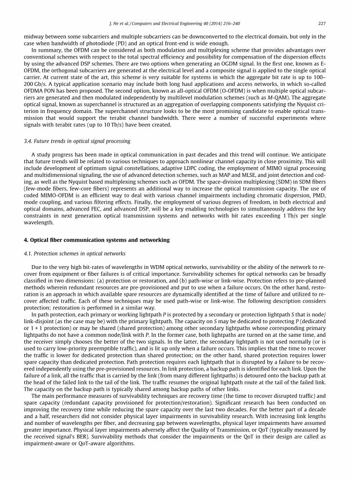
Due to the very high bit-rates of wavelengths in WDM optical networks, survivability or the ability of the network to re-cover from equipment or fiber failures is of critical importance. Survivability schemes for optical networks can be broadlyclassified in two dimensions: (a) protection or restoration, and (b) path-wise or link-wise. Protection refers to pre-plannedmethods wherein redundant resources are pre-provisioned and put to use when a failure occurs. On the other hand, resto-ration is an approach in which available spare resources are dynamically identified at the time of failure and utilized to re-cover affected traffic. Each of these techniques may be used path-wise or link-wise. The following description considersprotection; restoration is performed in a similar way.
In path protection, each primary or working lightpath P is protected by a secondary or protection lightpath S that is node/link-disjoint (as the case may be) with the primary lightpath. The capacity on S may be dedicated to protecting P (dedicatedor 1 + 1 protection) or may be shared (shared protection) among other secondary lightpaths whose corresponding primarylightpaths do not have a common node/link with P. In the former case, both lightpaths are turned on at the same time, andthe receiver simply chooses the better of the two signals. In the latter, the secondary lightpath is not used normally (or isused to carry low-priority preemptible traffic), and is lit up only when a failure occurs. This implies that the time to recoverthe traffic is lower for dedicated protection than shared protection; on the other hand, shared protection requires lowerspare capacity than dedicated protection. Path protection requires each lightpath that is disrupted by a failure to be recov-ered independently using the pre-provisioned resources. In link protection, a backup path is identified for each link. Upon thefailure of a link, all the traffic that is carried by the link (from many different lightpaths) is detoured onto the backup path atthe head of the failed link to the tail of the link. The traffic resumes the original lightpath route at the tail of the failed link.The capacity on the backup path is typically shared among backup paths of other links.
The main performance measures of survivability techniques are recovery time (the time to recover disrupted traffic) andspare capacity (redundant capacity provisioned for protection/restoration). Significant research has been conducted onimproving the recovery time while reducing the spare capacity over the last two decades. For the better part of a decadeand a half, researchers did not consider physical layer impairments in survivability research. With increasing link lengthsand number of wavelengths per fiber, and decreasing gap between wavelengths, physical layer impairments have assumedgreater importance. Physical layer impairments adversely affect the Quality of Transmission, or QoT (typically measured bythe received signal’s BER). Survivability methods that consider the impairments or the QoT in their design are called asimpairment-aware or QoT-aware algorithms.

228 J. He et al. / Computers and Electrical Engineering 40 (2014) 216–240
A comprehensive evaluation of various protection schemes in transparent networks with physical impairments is con-ducted in [21]. Besides the traditional blocking probability metric, a new metric, called the vulnerability ratio, is introducedto evaluate the network’s susceptibility to failures. The vulnerability ratio is defined as the probability that a randomly se-lected ongoing connection cannot be restored due to a random failure event. For dedicated path protection, it is noted in [21]that the performance of the network (both blocking probability and vulnerability ratio) is impacted by the choice of keepingthe backup path lighted up or dark. Lighting up the backup path introduces additional crosstalk and affects the ability to setup other lightpaths. On the other hand, keeping the backup path dark ensures that other lightpaths do not suffer from theadditional crosstalk that might otherwise exist; however, the backup path may turn out to not have sufficient QoT (with ahigher probability) in case it is needed.
Link protection is also investigated in [21]. Backup paths for links are selected using an algorithm presented in [22] to find a2-connected directed subgraph of the network graph. Let this directed subgraph be the blue digraph (directed graph). At thesame time another subgraph, called as red digraph, which is the same as the blue digraph but with edge directions reversedis also formed. Half of the available wavelengths, say set L1, are assigned to be used by primary paths on the blue digraphand by protection paths on the red digraph. The remaining set of wavelengths, say set L2, are used to carry primary data onthe red digraph and protection data on the blue digraph. Upon arrival, a connection can be routed on either of the two digraphs,using the wavelength set assigned for the primary data on that digraph. Shortest path routing with first-fit wavelength assign-ment is used to find the primary path. In case of a link failure, those connections that were using that link on the blue digraphdirection, which are using a wavelength in L1, are routed on the back up path on the red digraph around that link.
Extensive numerical results in [21] produced the following findings. The lit backup path protections schemes had consid-erably worse blocking that dark backup schemes, especially at lower loads. An interesting observation was that the darkbackup scheme also produced lower vulnerability ratios. The results also suggested that link protection might not be appro-priate for physically-impaired networks. A link’s backup path tends to be long; this backup path combined with the rest ofthe (surviving) links on the lightpath might make the restoration lightpath (i.e., lightpath after failure) to be too long to resultin good QoT.
4.2. Cross-layer design of optical networks
In recent years, new cross-layer techniques that incorporate information from multiple layers, such as physical layer infor-mation and networking layer information, have been the subject of intense research [23]. One of the major research activitiesaimed at designing powerful routing and wavelength assignment with impairment awareness that auto-adapt to the instanta-neous network state and minimize the effects of the physical layer impairments [24]. Other cross-layer designs, such as energy-aware, have also been proposed by researchers to optimize the network in terms of various performance metrics [25]. Thesecross-layer technologies utilize the cross-layer feedback and exchange information crossing multiple communication layersto achieve improvement in many aspects, such as QoS, latency, CAPEX/OPEX cost, and energy efficiency [23].
Cross-layer design is an essential part to implement and manage of robust scalable and dynamic networks and satisfiesneeds of new network elements, such as ROADMs to enable new functionalities to support society’s demand for networkbandwidth. The topics in cross-layer design cover bottom-up impacts of the physical and lambda layers (e.g. linear and non-linear noises and wavelength grid) to upper layers, as well as top-down approaches to reduce physical layer impairmentsand satisfy service requirements [23]. For example, the physical layer would perform proactive packet protection switchingto reroute data traffic to an available path in the case of fiber failure or impairment degradation. Then degraded messageswithin a data flow can be proactively detected with cross-layer logic prior to the onset of uncorrectable bit errors[LaiCP2012]. As another example of top-down approaches, routing decisions can be made based on other layers’ situation,such as QoT on physical layer so that the impact of physical impairments can be minimized [24].
4.2.1. Design of impairment-aware routing and wavelength assignmentAs an optical signal propagates along a lightpath to its destination in wavelength-routed optical networks, the signal’s
quality of transmission (QoT) is degraded by physical impairments, such as crosstalk, which is induced by other signals tra-versing the same optical crossconnects, demultiplexers, and fiber segments. Consequently, the signal’s bit error rate (BER) atthe destination’s receiver might become unacceptably high. Thus optical fiber components and intermediate switchingnodes can be the dominant reason calls are blocked in wide-area all-optical wavelength division multiplexed networks.Moreover, estimating the impact of the physical impairments on the quality of a lightpath before provisioning it can causea significant delay, which also affects the performance of networks because the latency worsens the contention and de-creases the network utilization.
The origins of impairments are highlighted in Fig. 4.2.1, which shows a typical lightpath comprising n hops [26]. Nodecrosstalk, fiber nonlinearities, and other noises can be modeled in [27]. A lot of physical impairments depend on the pathor on other wavelengths. For example, four-wave mixing (FWM) crosstalk depends on the spectral positions of active wave-lengths [Pointurier2006]. Consequently, the algorithms in upper layers should consider their impacts on the QoT, usuallyreferred as to QoT-aware or impairment-aware algorithms. Usually in literature, the QoT is equivalent to the BER, whichcan be estimated using the physical models in [27]. Other quality measurement metrics can also be used to measure theQoT. For example, in ultra-high capacity systems, such as 40 Gbps and 100 Gbps systems, polarization mode dispersion(PMD) can become important.
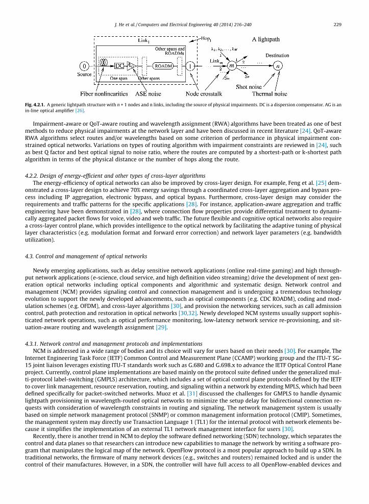
Fig. 4.2.1. A generic lightpath structure with n + 1 nodes and n links, including the source of physical impairments. DC is a dispersion compensator. AG is anin-line optical amplifier [26].
J. He et al. / Computers and Electrical Engineering 40 (2014) 216–240 229
Impairment-aware or QoT-aware routing and wavelength assignment (RWA) algorithms have been treated as one of bestmethods to reduce physical impairments at the network layer and have been discussed in recent literature [24]. QoT-awareRWA algorithms select routes and/or wavelengths based on some criterion of performance in physical impairment con-strained optical networks. Variations on types of routing algorithm with impairment constraints are reviewed in [24], suchas best Q factor and best optical signal to noise ratio, where the routes are computed by a shortest-path or k-shortest pathalgorithm in terms of the physical distance or the number of hops along the route.
4.2.2. Design of energy-efficient and other types of cross-layer algorithmsThe energy-efficiency of optical networks can also be improved by cross-layer design. For example, Feng et al. [25] dem-
onstrated a cross-layer design to achieve 70% energy savings through a coordinated cross-layer aggregation and bypass pro-cess including IP aggregation, electronic bypass, and optical bypass. Furthermore, cross-layer design may consider therequirements and traffic patterns for the specific applications [28]. For instance, application-aware aggregation and trafficengineering have been demonstrated in [28], where connection flow properties provide differential treatment to dynami-cally aggregated packet flows for voice, video and web traffic. The future flexible and cognitive optical networks also requirea cross-layer control plane, which provides intelligence to the optical network by facilitating the adaptive tuning of physicallayer characteristics (e.g. modulation format and forward error correction) and network layer parameters (e.g. bandwidthutilization).
4.3. Control and management of optical networks
Newly emerging applications, such as delay sensitive network applications (online real-time gaming) and high through-put network applications (e-science, cloud service, and high definition video streaming) drive the development of next gen-eration optical networks including optical components and algorithmic and systematic design. Network control andmanagement (NCM) provides signaling control and connection management and is undergoing a tremendous technologyevolution to support the newly developed advancements, such as optical components (e.g. CDC ROADM), coding and mod-ulation schemes (e.g. OFDM), and cross-layer algorithms [30], and provision the networking services, such as call admissioncontrol, path protection and restoration in optical networks [30,32]. Newly developed NCM systems usually support sophis-ticated network operations, such as optical performance monitoring, low-latency network service re-provisioning, and sit-uation-aware routing and wavelength assignment [29].
4.3.1. Network control and management protocols and implementationsNCM is addressed in a wide range of bodies and its choice will vary for users based on their needs [30]. For example, The
Internet Engineering Task Force (IETF) Common Control and Measurement Plane (CCAMP) working group and the ITU-T SG-15 joint liaison leverages existing ITU-T standards work such as G.680 and G.698.x to advance the IETF Optical Control Planeproject. Currently, control plane implementations are based mainly on the protocol suite defined under the generalized mul-ti-protocol label-switching (GMPLS) architecture, which includes a set of optical control plane protocols defined by the IETFto cover link management, resource reservation, routing, and signaling within a network by extending MPLS, which had beendefined specifically for packet-switched networks. Muoz et al. [31] discussed the challenges for GMPLS to handle dynamiclightpath provisioning in wavelength-routed optical networks to minimize the setup delay for bidirectional connection re-quests with consideration of wavelength constraints in routing and signaling. The network management system is usuallybased on simple network management protocol (SNMP) or common management information protocol (CMIP). Sometimes,the management system may directly use Transaction Language 1 (TL1) for the internal protocol with network elements be-cause it simplifies the implementation of an external TL1 network management interface for users [30].
Recently, there is another trend in NCM to deploy the software defined networking (SDN) technology, which separates thecontrol and data planes so that researchers can introduce new capabilities to manage the network by writing a software pro-gram that manipulates the logical map of the network. OpenFlow protocol is a most popular approach to build up a SDN. Intraditional networks, the firmware of many network devices (e.g., switches and routers) remained locked and is under thecontrol of their manufactures. However, in a SDN, the controller will have full access to all OpenFlow-enabled devices and

230 J. He et al. / Computers and Electrical Engineering 40 (2014) 216–240
thus collect statistics (e.g., ports’ packet counts, flow entry duration time). Thus, to implement new services and convergencefor optical networks, SDN technology (e.g. OpenFlow protocol) is a promising solution compared with other technologies,such as GMPLS [36]. Researchers can develop the OpenFlow controller with new capabilities, such as convergence of pack-et-circuit optical networks and QoT-awareness (networks can recover from fiber cut-off, high impairments, etc.) which canhelp drive next generation optical networks as well [34,35]. Note that these capabilities could be implemented with GMPLS/SNMP/TL1. But these protocols’ distributed nature and interactions make the solutions so complex and bring some architec-tural drawbacks and the implementation deficiencies [28].
4.3.2. NCM for situation-awareness and dynamic service provisioningA NCM of today’s optical networks is generally not able to collect and exchange cross-layer information and is thus unable
to support situation-aware operations, e.g. engaging emerging physical layer technologies in a cross-layer regime [32]. Inrecent years, bringing situational awareness to NCM has been intensively studied [32]. As described in [32], situation-awarecapability is one of the most desired features in the development of optical control plane. It will provide automatic serviceprovisioning using the control plane at multiple technology layers to improve network utilization, network survivability, en-ergy efficiency, and quality of service while reducing CAPEX/OPEX cost in optical networks. For example, re-provisioning avideo streaming service requires dynamic assignment of associated bandwidth in the transport service layer and also mea-surement of the QoT in the photonic physical layer [28]. In [33], the authors developed an impairment aware network plan-ning and operation tool, called NPOT for transparent optical networks and measured the network performance with physicalimpairment constraints in terms of lightpath setup time and lightpath blocking probability.
Usually, situation-aware operations need to adaptively reconfigure the network through dynamic service provisioningwith the support of the protocol extensions. In [37], the authors experimentally demonstrated dynamic wavelength pathcontrol and dynamic lightpath recovery in a multi-vendor wavelength-switched optical network testbed based on a GMPLScontrol plane. Lu et al. [38] proposed an auxiliary-graph based algorithm to set up dynamic multi-path service provisioningunder differential delay constraint in elastic optical networks based on the differential delay upper-bound and thebandwidth allocation granularity. In [28], the authors demonstrate a unified OpenFlow control plane and demonstrateapplication-aware traffic aggregation by using a centralized controller. Mo et al. [35] experimentally presentedthe QoT-awareness in converged OpenFlow-enabled networks with the demonstration of QoT-aware wavelength reassign-ment and QoT-aware path re-routing. Mo et al. [35] presented a NCM design to enable QoT-awareness in convergedelectronic and optical networks using OpenFlow protocol. It proposed a translation agent, which can translate the cross-layerinformation, such as OSNR reading from optical performance monitoring (OPM) devices into OpenFlow protocol messageand OpenFlow protocol message into TL1 protocol.
4.4. Fiber optic system analysis
Optical networks, and the fiber transmission links they comprise, are complex nonlinear dynamic systems, and as suchare difficult to analyze. In this section of the paper we address the modeling of optical fiber links, addressing common phys-ical layer impairments such as dispersion, nonlinearity, noise, and crosstalk, and then use these models to quantify the qual-ity of transmission (QoT) that can be provided by optical networks operating over these degraded links. Network analysisthus exploits large-scale simulation as well as simplified probabilistic modeling.
A system designer might have different reasons to perform system modeling, and these reasons then command differentapproaches. One important reason to understand and model the fiber channel mathematically is to mitigate physical impair-ments, through the use of either optical techniques or electrical signal processing algorithms. A second important reasonwould be to predict the performance of the system under various network conditions so that network design and manage-ment can be more effective.
Physical impairments can come from the fiber channel itself, such as dispersion and nonlinear crosstalk, or from externalsources, such as amplified spontaneous emission (ASE) noise from optical amplifiers. The former self-imposed impairmentscan be classified as intrachannel (within one wavelength) or interchannel (across wavelengths). If impairment mitigation isthe goal, these degradations are modeled as deterministic, given the data. If average performance measures are sought, theseare treated as random, and added to the inherently stochastic ASE noise. In this section we present a survey of techniqueswhich we broadly classify as channel modeling and performance prediction.
4.4.1. Fiber modeling techniquesThe so-called nonlinear Schrödinger (NLS) equation is used to model the propagation of optical pulses inside single-mode
fibers (SMF). For pulse widths longer than 5 ps, the NLS equation is given by [39]
dAdz¼ �a
2A� ib2
2d2Ad t2 þ icjAj2 A; ð1Þ
where A = A(t, z) is the slowly varying complex envelope of the propagating field; t is time measured in a frame of referencemoving at the group velocity; z is the propagation distance measured along the fiber; a, b2, and c are the fiber attenuation,group-velocity dispersion, and nonlinearity parameters, respectively. The three terms on the right hand side (RHS) of (1)

J. He et al. / Computers and Electrical Engineering 40 (2014) 216–240 231
describe, respectively, the effects of fiber losses, dispersion, and nonlinearities affecting pulses propagating through opticalfibers.
The main effect of group velocity dispersion (GVD) is to temporally broaden optical pulses as they propagate through thefiber. Temporal spreading makes neighboring bits overlap, leading to intersymbol interference (ISI). In addition to GVD, pulsebroadening can be caused by polarization-mode dispersion (PMD) due to fiber birefringence. Both types of dispersion areinherently linear phenomena. Fiber nonlinearities can be classified into two types: the Kerr effect and stimulated scattering.Stimulated scattering leads to intensity-dependent gain or loss, the most detrimental of which is stimulated Raman scatter-ing (SRS). The Kerr effect is due to the intensity dependence of the refractive index and causes a data-dependent phase shift[39]. Stimulated scattering is relatively small compared with the Kerr effect. When successive optical pulses are transmittedin a multichannel system, the Kerr effect leads to nonlinear intrachannel effects—self-phase modulation (SPM), intrachannelcross-phase modulation, (IXPM), and intrachannel four-wave mixing (IFWM))—as well as nonlinear interchannel effects—cross-phase modulation (XPM) and four-wave mixing (FWM). Both SPM and XPM lead to spectral broadening [40]. FWMgenerates new waves at the phase-matching frequencies. IXPM results in timing jitter and IFWM results in amplitude jitterand ghost pulse generation [40].
The NLS equation is a nonlinear partial differential equation (PDE), and as such exact analytic solutions are in most casesdifficult to obtain. Instead approximate methods are used. They can be broadly classified as either numerical methods, suchas the slit-step-Fourier simulation method, and linearization methods, including the Volterra series transfer function (VSTF)method [41] and the regular perturbation (RP) method [42].
The split-step Fourier method (SSF) is a pseudospectral method that has been used extensively to solve the NLS equation.The length of the fiber is subdivided into small segments, and linear and nonlinear operators are applied successively overeach segment. The linear operator is implemented in the frequency domain to save computation, thus the name. The SSFmethod is usually taken as the standard of accuracy for validating other methods in the absence of experimental data,due to its well-established ability to accurately model numerous physical impairments and simulate the pulse propagationin fibers.
The Volterra series is a nonlinear expansion that provides an input–output relationship of a system with memory up tononlinear finite polynomial order. The VSTF method expresses the NLS equation as a nonlinear transfer function in the fre-quency domain, retaining only the most significant terms (Volterra kernels) [41]. The RP method, first applied to the NLSequation in [42], is a small-signal approximation, applicable when the nonlinearity is weak. Both the VSTF and RP methodshave been broadly used to characterize nonlinear effects. A computationally-efficient two-dimensional discrete-time andwavelength model was constructed based on the VSTF approach in [43].
4.4.2. Performance predictionTwo important measures of performance of communication systems are the probability or error (or bit error rate, BER)
and the channel capacity, both derived from a probabilistic description of the channel. The exact performance expressionsunfortunately do not take on simple globally-applicable forms in fiber-optic systems as in the RF communication case. Theapproach is to use approximate expressions, and apply them judiciously.
The most popular technique to estimate the performance of fiber-optic communications systems is to use a simple Gauss-ian noise approximation on both the effects of physical impairments and on the ASE noise. The ASE noise is due to sponta-neous emission that adds optical noise to the signal during its amplification. The spectral density of ASE noise is nearlyconstant (white noise) in the band of interest and can be expressed by SASE = nsphm0(G � 1), where nsp is the spontaneousemission factor, h is Planck’s constant, and m0 is the carrier frequency of the signal being amplified. Assuming that all ampli-fiers are operated with the same gain G, the total ASE power for a chain of N amplifiers through a linear fiber is approximatedby PASE = 2NSASEDm0, where the factor of two takes into account the unpolarized nature of ASE noise and Dm0 is the bandwidthof the optical filter [39]. The probability distribution of the ASE noise at the receiver is well-modeled as a Gaussian for mod-erate fiber lengths.
The bit error rate (BER) of a system affected by Gaussian noise can be estimated given the first and second order statisticsof the received decision variable. In fiber systems, these statistics are collected after the photodetection circuit, and dependon the type of modulation used. For on–off-keying modulation, the decision variable is the sampled filtered output of thephotodetector and for differential phase-shift keying (DPSK), a differential balanced detector is used [39]. For either case,
the BER can be approximated using BER ¼ 12 er fc Qffiffi
2p� �
, where the metric Q is referred to as the Q-factor, and is defined as
Q ¼ l1�l0r1þr0
, where li and ri are the mean and standard deviations, respectively, of the received sample given bit i e {0, 1}.
The standard deviations ri can include the effects of ISI and nonlinearity. Alternatively, impairments can be accounted foras power penalties.
More detailed analytical expressions for the decision sample variance and the probability distribution of the nonlinearphase noise caused by the interaction of ASE with fiber nonlinearity have been discussed in recent literature. Mafi andRaghavan [44] models the optical fiber channel in the presence of nonlinear phase noise and presents bit error rate resultsfor a WDM DPSK system. In [45], the authors calculate the variance of the nonlinear phase noise in an orthogonal-frequency-division-modulated (OFDM) system. In [46], the authors propose and verify, with simulation and experiments,an empirical phase noise channel model for a long-haul optical system. The results agree with the data in the case of QPSKtransmission. Optical networks transitioning to higher (100 Gbps+) data rates often must operate using multiple

232 J. He et al. / Computers and Electrical Engineering 40 (2014) 216–240
line-rates, requiring special consideration; 10 Gbps links spectrally adjacent to higher data rates cause the strongestdegradation, modeled in [48].
New advances to optical networks have stimulated new analytical formulations. Many approaches for coherent detectionschemes assume a colored Gaussian noise model; both simulation and experimental verifications on this hypothesis havebeen conducted. Very recently, dispersion uncompensated coherent detection systems have become popular. In [47], the ef-fects of ASE noise and nonlinearity through uncompensated long-haul fibers are modeled. A power-spectral-density for thenonlinear crosstalk for uncompensated coherent links is derived in [50]. In [49], the effects of IFWM for both dispersion-managed and uncompensated systems are accurately modeled as a Gaussian random variable.
When an exact expression for the error probability is sought, a popular approach is to employ a Monte Carlo simulationusing the time-consuming SSF method. All significant physical impairments can be effectively modeled. The computationalcomplexity is significant, and increases with the inverse of the expected BER. Estimating an error-probability below, say,10�9, requires too many trials to predict accurately. An example of the performance of a typical fiber optic system obtainedusing the SSF method is given in Fig. 4.4.1. Note that for power levels above 3 dBm the nonlinear effects dominate, making aGaussian approximation in this region somewhat suspect.
Often network designers concerned with computational complexity and speed want a coarser approximation to the per-formance on any given lightpath, especially if the performance estimation needs to be done in real-time. The only measure ofreal interest then becomes whether the lightpath is able to satisfy a quality of transmission (QoT) constraint of not. Manyresearchers have then relied on a simple transmission reach constraint. The transmission reach is the distance a modulatedsignal can travel all-optically down a fiber and still achieve a pre-determined QoT, often specified as a BER < 10�3 beforeerror control coding.
4.5. Future trends
In the area of network protection, new protection schemes are needed to dynamically reconfigure the network with theintegration of newly developed optical devices, such as optical performance monitor. Some emerging technologies, such assoftware defined networking, will also increase the dynamicity in optical path protection, which is another possible futureresearch direction. One of future trends in cross-layer design of optical networks is to consider the convergence of opticalcircuit network and other packet networks, including wireless or wireline. Optical networks Control and management alsoneeds to consider this new trend and extend its architecture and design to support the convergence. In the area of fiber opticsystem analysis, since the accurate analysis of fiber-optic systems depends strongly on the technology used, it will continueto evolve as more sophisticated optics are employed in these systems. The nonlinear behavior, once sufficiently understoodmay someday be considered an asset, and drive the development of even higher capacity future communication systems.
5. Free space optical communications
Wireless transmission has multiple advantages over cabled systems, including ease and cost of deployment, mobility, andnetworking flexibility. Free space optical (FSO) systems, which transmit data-modulated optical signals through the atmo-sphere instead of fiber, aim to combine the high bandwidth quality of optical transmission with the primary benefits of wire-less systems. Approaches have been proposed for two main applications: ‘last-mile’ network connectivity (1–4 km), andindoor personal communications (1–10 m). Significant tradeoffs between FSO and other technologies exist, such as weathersusceptibility, acquisition, pointing and tracking (APT) issues, shadowing, and safety, inspiring a rich body of recent work in
Fig. 4.4.1. Simulation of BER versus received optical power for a periodically amplified and dispersion managed system operating at 10 Gb/s.

J. He et al. / Computers and Electrical Engineering 40 (2014) 216–240 233
the field. This section surveys the state-of-the-art in FSO technology, summarizes the broad literature and discusses futuretrends.
5.1. Short-range FSO
Free space optical communications for short-range applications became popular due to the low cost and high reliability ofoptoelectronic devices developed for fiber-optic systems. The primary applications are urban or suburban last-mile connec-tivity, wireless network backhaul to an internet gateway, and dedicated point-to-point applications, usually assumingstationary roof-top or tower-top mounting. The range is limited to a few kilometers, and systems handle data rates up toa few Gb/s.
FSO systems are designed to use infrared lasers, using optics (telescopes) to form a beamwidth on the order of 1–5 mrad.Photodetection (PD) relies on either a pin photodiode or an avalanche photodiode (APD). Transmit power levels are limitedto a few mW due to eye-safety limits, and therefore systems are strongly signal-to-noise ratio (SNR) limited, especially if thesun or other strong optical emission falls in the field of view of the receiver, generating additional shot noise. The FSO chan-nel rarely experiences temporal dispersion from the channel itself, since the beam is so narrow. The additional advantage ofusing a narrow beamwidth is that the received power density is increased. The counterbalance to this is that if the beam istoo narrow, then active APT is required to maintain the link in slowly-varying environments, which can be due to physicaleffects such as building sway [54]; ATP hardware significantly increases the cost of the system.
One of the main limitations of FSO technology is its susceptibility to weather. Fog or heavy snow can impair the systemcatastrophically. FSO systems that are implemented in geographic regions predisposed to poor weather often have a backupsystem to provide some connectivity if the optical link is lost due to severe attenuation. This can be done using a parallel RFlink, which can support a fraction of the data rate that the FSO link can handle in clear weather. This idea has led to the recentdesign and analysis of hybrid RF/FSO modulation and coding techniques [53].
In clear weather, the FSO channel is affected by scintillation caused by turbulent atmosphere. This stochastic fading phe-nomenon that can degrade the link by over 10 dB/km has been modeled as log-normal, gamma–gamma [51], or k-distrib-uted. To combat this problem, multiple-input multiple-output (MIMO) techniques have been explored [52], illustrated inFig. 5.1.1. If Q-PPM (pulse position modulation) is used as the modulation with repetition coding across the M lasers, andassuming no significant background radiation falls upon the N photodetectors, the symbol error probability can be approx-imated as [52]. Results for lognormal fading are given in Fig. 5.1.2 as the received peak power varies. Multiple transceiverscan offer great advantage over single transceivers in turbulent atmospheric channels.
The MIMO FSO system differs substantially from the MIMO RF channel because of incoherent (or partially coherent) sig-nal combining inevitable at the receiver, making space–time coding practically ineffective. Techniques attempting to circum-vent this problem have been popular in the recent literature.
FSO transmit devices are fundamentally peak power limited, and the channel is highly variable. New robust and adaptivemodulation and coding techniques especially designed for peak-power limited systems have emerged that can increase thethroughput and/or spectral efficiency of these systems. Variants of pulse position modulation have been explored [55] aswell as differential techniques [56]. Coherent detection is another option that can increase the receiver sensitivity by multi-ple decibels. Error control coding has been widely applied as well [51].
Using these highly directed FSO beams within the context of multipoint networks has been particularly challenging. StaticFSO networks behave like wired networks. Adaptive FSO networks have been proposed where each node comprises one ormore FSO transceiver that can be pointed in various directions, so that the network becomes reconfigurable. Often these net-works are paired with RF mesh networks, forming hybrid RF/FSO systems [57].
5.2. Visible light communications
The prospect of indoor communications using infrared (IR) radiation began in earnest in the early 1980s, the only vestigeof that early work being appliance remote control devices, which are largely still implemented using IR technology. There iscurrently a resurgence of interest in indoor wireless optical communications, due in large part to the advent of LED arrayillumination devices, and the potential of using these simultaneously for lighting and communications [58]. The resultingfield is referred to as visible light communications (VLC), as is primarily focused on personal communications, such as forportable phones and laptop computers. VLC systems use white light emitting diode (LED) as the optical source, and pinreceivers as the photodetector. For the system downlink, the LED arrays are modulated at high speeds, too fast for the human
Fig. 5.1.1. Schematic of an atmospheric line-of-sight MIMO FSO system using M lasers and N photodetectors (PD).

-90 -85 -80 -75 -70 -65 -60 -55 -50 -45 -4010
-10
10-8
10-6
10-4
10-2
100
Pr in dBW
Ps
non-fading, M = N = 1M = 1, N = 1M = 2, N = 1M = 4, N = 1M = 1, N = 2M = 1, N = 4
Fig. 5.1.2. Symbol error rate for MIMO FSO system as a function of the average received power level per photodetector, assuming lognormal fading. M is thenumber of transit lasers and N is the number of photodetectors.
Fig. 5.2.1. Application of VLC to indoor office environment.
234 J. He et al. / Computers and Electrical Engineering 40 (2014) 216–240
eye to respond. For the uplink, a complementary system using a different wavelength such as IR is envisioned. In addition tolarge numbers of research programs exploring this idea, there is an IEEE standardization effort also devoted to VLC, the IEEE802.15.7 WPAN. Potential applications of VLC include the indoor channel (using LED lighting), illustrated in Fig. 5.2.1, andvehicular communications (using, e.g., traffic lights).
The indoor optical channel presents many modeling difficulties, as is it highly dependent on the room configuration,reflective surfaces, transceiver placement, etc. The channel impulse response is typically modeled as a narrow direct lineof sight (LOS) component followed by a long tail due to non-line-of-sight reflections. Depending on the room size the result-ing intersymbol interference can be significant, and can limit the data throughput to just a few Mb/s, making this channelquite different from the outdoor FSO link.
Using white lighting LED arrays for indoor communications also presents many intriguing challenges that have stimu-lated a flurry of research in the last year or two. The primary difficulty is increasing the data rate in light of the bandwidthand linearity limitations imposed by the white LEDs and multipath dispersion caused by the diffuse indoor channel. WhiteLEDs have a time response that is well modeled as HðxÞ ¼ e�x=xb , where xb is an empirically fitted coefficient that dependson the device. Techniques to increase the data rate broadly fall into two categories: spatial multiplexing and higher-ordermodulation. The former technique exploits the potential of directed LED sources carrying different information so that spa-tial multiplexing gain can be easily obtained via an imaging receiver [59]. The later exploits the high expected signal to noiseratio to increase the spectral efficiency of the modulation, keeping eye safety, peak-to-average power ratios (PAPR), dim-ming, and LED switching speeds in mind. Using a variant of PMM called EPPM [55], the modulation scheme can be easilymodified to adapt to different required PAPR while remaining power efficient, as seen in Fig. 5.2.2.
5.3. Future trends in FSO
Free space optics has been an intensifying area of research, partly because devices have become less expensive, more reli-able, and more powerful, and partly because the RF spectrum has become overly congested. As society’s demand for higherdata rates increases, FSO systems will play a larger role in providing needed connectivity. Future trends in research include

1 2 3 410
-7
10-6
10-5
10-4
10-3
10-2
10-1
100
Peak Power, P0
BE
R
cooperative relaying, distributed MIMO, heterogeneous technology networks, and the use of adaptive signal processing tocombat distortion and interference. As white LED technology advances, research in indoor visible light communications willcontinue to progress. In the future, approaches for increasing the throughput of systems and allow multiuser transmissionwill be especially welcome. System integration approaches, perhaps combining VLC with power-line communications, willalso be of great interest.
6. Emerging technologies
6.1. Optics in data center networks
Large data centers built one decade from now have thousands of servers and need to process multiple terabits datathrough massive multi-core processing. The interconnections between servers within data center and between data centersquickly approach the limit of electronic transmission and will predominately use optics to transport data. Multiple hybridelectrical/optical architectural designs are proposed to provide a viable path to a scalable solution [60,62]. Furthermore, opti-cal components, such as large port count switches and low cost ROADM, are developed to satisfy new requirements in datacenter communications [63,65]. Optics can also be used for on-chip communications to achieve space-, power- and spec-trally efficiency [66].
Optical circuit switched networks can provide the larger bandwidth than packet switched network. This fact motivatesresearchers to explore how optical circuit switching technology can benefit data center networks [60,61]. Currently, thearchitecture of data center network is changing by integrating emerging optical technology and components. Lam et al.[63] reviewed growing trend of warehouse-scale mega-datacenter computing, the network transformation driven bymega-datacenter applications, and the opportunities and challenges for fiber optic communication technologies to supportthe growth of mega-datacenter computing. As indicated by [63], datacenter networks use the full spectrum of fiber optictechnologies, from short reach to long haul. For example, potential technologies to realize next generation intra-datacenterinterconnects include advanced signal modulation and electronic dispersion compensation.
For hybrid architectures, Farrington et al. [60] presented a hybrid electrical/optical switch architecture (called Helios) thatcan deliver significant reductions in the number of switching elements, cabling, cost, and power consumption. In Helios, Coreswitching can be either electrical packet switching or optical circuit switching; the circuit-switched portion handles base-line, slowly changing inter-pod communication and the packet-switched portion delivers all-to-all bandwidth for the burstyportion of inter-pod communication [60]. Farrington et al. [60] also explored Helios’s architectural tradeoffs and challenges.For example, in Helios, some communication patterns will lead to poor but fair performance, or excellent but unfair perfor-mance when considering individual pod-level traffic demands [60]. In [61] a hybrid packet and circuit switched data centernetwork architecture (called HyPaC) is proposed to augment the traditional hierarchy of packet switches with a high speed,low complexity, rack-to-rack optical circuit-switched network to supply high bandwidth to applications. Wang et al. [61]also discussed the fundamental requirements and design options of HyPaC and demonstrated a prototype system calledc-Through, where the responsibility for traffic demand estimation and traffic de-multiplexing resides in end hosts, makingit compatible with existing packet switches.
Furthermore, WDM technology provides the promise of delivering scalable optical interconnects with low powerconsumption, high data throughput, long transmission distance, and the cost effectiveness needed for future warehouse-scale datacenter networks [62]. Hong et al. [62] surveyed the growing need for optical interconnect bandwidth in datacenternetworks, and the opportunities and challenges for wavelength division multiplexing (WDM) to sustain the ‘‘last 2 km’’

236 J. He et al. / Computers and Electrical Engineering 40 (2014) 216–240
bandwidth growth inside datacenter networks. Emerging optical technologies, such as Photonic Integrated Circuits (PICs)and Quantum dot (QD) laser, are reviewed in [62]. Schares et al. [65] studied the progress towards integrating new opticaltechnologies deeper into datacenter systems and discussed the prospects of alternative optically enabled architectures fordata center applications. Schares et al. [65] also discussed how a software controlled optical circuit switch enabled a low-latency stream computing system, which is particularly attractive for data-driven workloads that have long-lived circuit-likecommunication patterns, such as streaming applications. Moreover, Schares et al. [65] reviewed emerging research of opti-cally attached memory systems.
The network control plane is also playing an important role in intra/inter datacenter communications. Rofoee et al. [64]reported on a user/application-driven multi-technology optical sub-wavelength network based on an extended GMPLS-PathComputation Engine (PCE)-Sub-wavelength Assignment Engine (SLAE) based control-plane, which enables innovative appli-cation driven end-to-end sub-wavelength path setup and resource reservation across the multi technology data-plane. Theenhanced GMPLS-PCE -SLAE control-plane sets up application driven paths across the two sub-wavelength technologies ofTSON and Optical Packet Switch Transport (OPST), which are interconnected through pre-established optical connections[64]. As shown in [64], a very low latency data delivery is achieved by the enhanced control plane in testbeds, which alsodemonstrated flexible connectivity patterns with various bit rates by taking advantage of statistical multiplexing natureof the sub-wavelength technologies. In addition to the systems, optical components, such as transceivers are, are discussedin [66], which described how transceivers based upon a building-block/optical-engine approach could successfully addressthe interconnect requirements of the datacenter and lead to cost-effective solutions that are commercially viable.
6.2. Convergence of optical and other networks
Nowadays, optical circuit networks and electronic packet networks start to converge under the new technologies, e.g.ROADM, GMPLS, and software defined networking (SDN). This new trend is driven by the ever increasing bandwidth demandand new applications, such as mobile backhaul and huge data transfer inter/intra data centers. The convergences of opticalcircuit networks (i.e. transport network) and electronic packet networks (IP network) provide more capabilities that currentnetworks do not have, leading to significant improvement of Capex and Opex efficiencies for the providers. For example, theoptical network today remains largely static under the provider’s manual control, it takes days to set up/provision a newcircuit/connection for customers. In a converged packet-circuit network, the service provisioning time can be shortenedto seconds. Meanwhile, convergence of optical and wireless networks has been studied and radio-over-fiber (ROF) technol-ogy for converged networks came into play and has emerged as an affordable alternative solution to satisfy the increasingbandwidth demand of mobile broadband users [69,70].
6.2.1. Convergence of packet-switched and circuit-switched networksRecently, a few efforts have been made in the development of convergence of electronic packet and optical circuit net-
works [28,34]. There are two main approaches to realize the convergence, either through the extension of GMPLS or throughSDN technologies, e.g. OpenFlow. GMPLS approach has been implemented by major device vendors. For example, [29]described a converged dynamic network architecture based on GMPLS. It offers dynamic and on demand end-to-end deliveryof packet switched traffic over an optical circuit switched network. However, each vendor has its own proprietary implemen-tation of the control plane bringing interoperability issue and provides very limited visibility about control of the network.As discussed in [36], GMPLS has certain architectural drawbacks and the protocol deficiencies, which complicatesinformation exchange to achieve efficient cross layer service provisioning.
Fig. 6.2.1. Experimental diagram with proposed capabilities in packet-circuit OpenFlow network [MoWOFC2013].

J. He et al. / Computers and Electrical Engineering 40 (2014) 216–240 237
Recently, another SDN approach using OpenFlow gains a lot of attentions as a control framework to support programma-bility of network functions by decoupling the data plane and the control plane. Concepts of SDN and OpenFlow have beendescribed in Section 4.3. Several unified packet-circuit OpenFlow networks were demonstrated in [28,67] as proof-of-con-cept. Gudla et al. [67] demonstrated a simple proof-of-concept testbed, where a bidirectional wavelength circuit is dynam-ically created to transport a TCP packet flow.
With the unification of both types of networks, new capabilities can be developed for intelligent operation, such as cross-layer optimization and situation-awareness. For example, in [28], the authors demonstrate a unified OpenFlow control planeand show application-aware traffic aggregation by using a centralized controller, where circuit flow properties provide dif-ferential treatment to dynamically aggregated packet flows for different traffic (e.g. video and web). Das et al. [28] also out-lined new capabilities including dynamic packet links, dynamic service-aware aggregation and mapping, application-awarerouting, variable bandwidth packet links, and unified recovery. Similarly, [34] proposed extensions to OpenFlow by addingQoT-aware wavelength re-assignment function and protocol-aware multipath routing function in a converged packet-circuitnetwork. Fig. 6.2.1 shows the experimental diagram. As we discussed in Section 4.2, the physical impairments become majorperformance limitation because the pre-planning is not feasible for dynamic services in dynamic optical networks. Conse-quently, a type of situation-awareness, called quality-of-transmission (QoT) awareness is required in unified packet-circuitOpenFlow networks. In [34], the unified controller monitors the optical to noise ratio (OSNR) in the physical layer at opticalnodes. When the optical channel is interrupted by physical impairment or fiber cut, the controller detects the abnormalityand manages optical nodes to assign a new clean wavelength channel to avoid packet loss. Mo et al. [34] also experimentallydemonstrated protocol-aware multipath routing under traffic congestion, where all traffic routed along dynamically com-puted OSPF paths until congested. Different applications have different characteristics and thus different requirements.For example, the video streams have low-jitter requirement, and a high-data-rate IP traffic flow requires large bandwidthcapacity. The controller is aware of the links’ bandwidth utilization, traffic protocols, and traffic requirements and sets upmultipath routing to optimize the path for each traffic type to avoid link congestion.
6.2.2. Convergence of optical and wireless networksThe rapid growth of the number of mobile devices and video devices demands greater bandwidth and more reliable data
transmission than before. Wireless and optical technologies play a key role to satisfy these demands. Optical networks pro-vide transparency against data rate and signal format and high capacity and wireless networks provide ubiquitous and mo-bile access. They can be thought of as complementary and widely used in access networks, where the convergence of opticaland wireless networks is crucial [69]. Future broadband access networks must leverage on both technologies and combinethem seamlessly. This convergence enables boosting network penetration, correspondingly reduces OPEX and CAPEX, andsupports the creation of emerging and future applications and services [70].
As discussed in [70], converged fiber-wireless access networks target at combining the huge amount of available band-width of optical networks and the ubiquity and mobility of wireless access networks so as to reduce their cost and complex-ity. Key enabling optical and wireless technologies are also highlighted and the design challenges are also identified in [70].To provide broadband, ubiquitous access services, Kazovsky et al. [68] proposed a converged optical and wireless networkarchitecture, called CROWN, which consists of an optical backhaul and a wireless mesh. In [68], an integrated routing algo-rithm is also developed for CROWN to improve network performance using highly efficient load balancing. In addition topublic users, converged optical and wireless networks can serve mission-critical services in public safety and disaster reliefcommunications. A new emergency-aware architecture is introduced in [71] that support mission-critical services over thefiber-wireless integration. Dhaini and Ho [71] described the radio on free-space optics system, which simultaneously trans-mits multiple RF signals comprising heterogeneous wireless services over FSO links using wavelength-division multiplexingtechnology. Moreover, their technology can be applied as a universal platform for enabling seamless convergence of fiber andfree-space optical communication networks [71]. More details about recent results in convergence of optical and wirelessnetworks can be found in [69], which provides an up-to-date survey of this topic and overviews the state of the art, enablingtechnologies, and its future developments.
7. Conclusion
In this paper, we have shown various recent state of the art advances in optical communications. We review state of theart in optical components including optical modulators, optical switches, and ROADM. Modulators based on various mate-rials are discussed in terms of insertion loss, bit rates, nonlinear effect, and power consumption. Multiple different types ofswitches are listed and reviewed as well. A novel new switching approach based on DMD has also been reviewed, which hasa high port count, fast, low insertion loss. ROADM is also one of the essential elements to create a dynamically reconfigurableoptical network. We discussed its feature and architecture, which enable efficient use of all the wavelength resources for on-demand and high bandwidth network configuration and simplify the network architecture.
Signal processing in optical fiber communications is discussed, including advanced coding, modulation, detectionschemes and OFDM technology. Specifically, recent advances in LDPC, E-OFDM, and O-OFDM are reviewed and their advan-tages over conventional schemes are summarized. We also review the critically important functionalities in optical networksystem, including protection scheme, cross-layer design, optical network control and management. Mathematical methods

238 J. He et al. / Computers and Electrical Engineering 40 (2014) 216–240
to model the fiber and predict network performance are addressed to quantify QoT and other effects. FSO systems are de-scribed for last-mile network connectivity and indoor personal communications and future trends are summarized. Addi-tionally, emerging applications are discussed, including data center networking and converging optical and othernetworks. Several hot topics, such as GMPLS, software defined networking, packet-circuit network convergence, are re-viewed in the paper.
It is an exciting time for this field as we are witnessing optical communications to be widely used towards the end users.The overall conclusion is that optical communications (fiber and free space) will play a more important role in telecommu-nications and data center communications.
Acknowledgments
This research was supported by the National Science Foundation through the Center for Integrated Access Networks(CIAN) under grant number EEC-0812072.
References
[1] Nagarajan R et al. Large-scale photonic integrated circuits. IEEE J Sel Topics Quant Elec 2005;11:50.[2] DeRose CT, Himmlehuber R, Mathine D, Norwood RA, Luo J, Jen AKJ, et al. High n strip loaded electro-optic polymer waveguide modulator with low
insertion loss. Opt Express 2009;17:3316–21.[3] Dinu R, Jin D, Yu G, Chen B, Huang D, Chen H, et al. Environmental stress testing of electro-optic polymer modulators. J Lightwave Technol
2009;27:1527.[4] Witznes J, Baehr-Jones T, Hochberg M. Design of transmission line driven slot waveguide Mach–Zehnder interferometers and application to analog
optical links. Opt Express 2010;18:16902.[5] You S. Performance improvement of bandwidth-flexible reconfigurable optical add/drop multiplexers with wavelength converters. In:
Communications and photonics conference and exhibition, ACP, Asia, IEEE; 2011.[6] Lynn B, Blanche P, Miles A, Wissinger J, Carothers D, LaComb L, et al. Design and preliminary implementation of an N�N diffractive all-optical fiber
optic switch. Journal of Lightwave Technology 2013;31(24):4016–21.[7] Poole S, Frisken S, Roelens M, Cameron C. Bandwidth-flexible ROADMs as network elements. In: Optical fiber communication conference, OSA
Technical Digest (CD) paper OTuE1; 2011.[8] Papadimitrion GI. Optical switching. Hoboken: John Wiley & Sons Inc.; 2007.[9] Perrin Sterling. The need for next generation ROADM networks, white paper; 2010.
[10] Devarajan A, Sandesha K, Gowrishankar R, Kishore BS, Prasanna G, Johnson GR, et al. Colorless, directionless and contentionless multi-degree ROADMarchitecture for mesh optical networks. In: 2nd International conference on communication systems and networks (COMSNETS), January 2010. p. 1–10, 5–9.
[11] Li Y, Gao L, Shen G, Peng L. Impact of ROADM colorless, directionless, and contentionless (CDC) features on optical network performance [Invited]. J OptCommun Netw 2012;4:B58–67.
[12] Watanabe T, Suzuki K, Goh T, Hattori H, Mori A, Takahashi T, et al. Compact PLC-based transponder aggregator for colorless and directionless ROADM.In: OFC/NFOEC; 2011.
[13] Djordjevic IB, Xu L, Wang T. Statistical physics inspired energy-efficient coded-modulation for optical communications. Opt Lett 2012;37(8):1340–2.[14] Djordjevic IB, Liu T, Xu L, Wang T. On the multidimensional signal constellation design for few-mode fiber based high-speed optical transmission. IEEE
Photonics J 2012;4(5):1325–32.[15] Djordjevic IB. Energy-efficient spatial-domain-based hybrid multidimensional coded-modulations enabling multi-Tb/s optical transport. Optics
Express 2011;19(17):16708–14 [08/15/11].[16] Djordjevic IB, Arabaci M, Minkov L. Next generation FEC for high-capacity communication in optical transport networks. IEEE/OSA J Lightw Technol
2009;27(16):3518–30. August 15.[17] Djordjevic IB, Xu L, Minkov LL, Wang T, Zhang S. Polarization-multiplexed LDPC-coded QAM robust to I–Q imbalance and polarization offset. In: Proc
ACP 2010, paper no. SH3; 2010.[18] Cvijetic M, Djordjevic I. Advanced optical communication systems and networks. Artech House 2013.[19] Fontaine NK et al. Space-division multiplexing and all-optical MIMO demultiplexing using a photonic integrated circuit. In: Proc OFC/NFOEC,
postdeadline papers (OSA, 2012), paper PDP5B.1.[20] Xia TJ et al. 21.7 Tb/s field trial with 22 DP-8QAM/QPSK optical superchannels over 1503-km of installed SSMF. In: Optical fiber communication
conference, OSA technical digest (Optical Society of America, 2012), paper PDP5D.6; 2012.[21] Askarian A, Zhai Y, Subramaniam S, Pointurier Y, Brandt-Pearce M. Cross-layer approach to survivable DWDM network design. IEEE/OSA J Optical
Commun Netw 2010;2(6):319–31. June.[22] Medard M, Barry R, Finn S, He W, Lumetta S. Generalized loop-back recovery in optical mesh networks. IEEE/ACM Trans Netw 2002;10(1):153–64.[23] Subramaniam S, Brandt-Pearce M, Demeester P, Vijaya Saradhi C. Cross-layer design in optical networks. Springer; 2013.[24] Azodolmolky S, Klinkowski M, Marin E, Careglio D, Pareta JS, Tomkos I. A survey on physical layer impairments aware routing and wavelength
assignment algorithms in optical networks. Comput Netw 2009;53(7):926–44.[25] Feng M, Hinton K, Ayre R, Tucker R. Network energy efficiency gains through coordinated cross-layer aggregation and bypass. J Opt Commun Netw
2012;4:895–905.[26] He J, Brandt-Pearce M, Subramaniam S. Analysis of blocking probability for first-fit wavelength assignment in transmission-impaired optical networks.
IEEE/OSA J Opt Commun Netw 2011;3:411–25.[27] Agrawal G. Fiber-optic communication systems. 3rd ed. New York, NY, USA: Wiley; 2002.[28] Das S, Yiakoumis Y, Parulkar G, McKeown N, Singh P, Getachew D, et al. Application-aware aggregation and traffic engineering in a converged packet-
circuit network, OFC2011, NThD3.[29] CISCO, Optical impairment-aware WSON control plane for Cisco ONS 15454 MSTP. <http://www.cisco.com/en/US/prod/collateral/optical/ps5724/
ps2006/data_sheet_c78-689160.pdf>.[30] Doverspike RD, Yates J. Optical network management and control. Proc IEEE 2012;100(5):1092–104.[31] Muoz R, Martinez R, Casellas R. Challenges for GMPLS lightpath provisioning in transparent optical networks: wavelength constraints in routing and
signaling. IEEE Commun Mag 2009;47(8):26–34.[32] Daneshamand M, Wang C, Wei W, Long K. Advanced in optical network control and management. J Netw Syst Manage 2012;20:1–4.[33] Azodolmolky S, Perello J, Angelou M, Agraz F, Velasco L, Spadaro S, et al. Experimental demonstration of an impairment aware network planning and
operation tool for transparent/translucent optical networks. J Lightwave Technol 2011;29(4):439–48.[34] Mo W, He J, Karbassian M, Wissinger J, Peyghambarian N. Situation-aware multipath routing and wavelength reassignment in a unified packet-circuit
OpenFlow network. In: Optical fiber communication conference (OFC), March 2013. p. 1, 3, 17–21.

J. He et al. / Computers and Electrical Engineering 40 (2014) 216–240 239
[35] Mo W, He J, Karbassian M, Wissinger J, Peyghambarian N. Quality of transmission awareness in converged electronic and optical networks withOpenFlow. In: IEEE communications letters, vol. 17, no. 5, May 2013.
[36] Das S, Parulkar G, McKeown N. Why OpenFlow/SDN can succeed where GMPLS Failed, ECOC 2012, Paper Tu.1.D; 2012.[37] Liu L, Tsuritani T, Nishioka I, Huang S, Yoshida S, Kubo K, et al. Experimental demonstration of highly resilient wavelength switched optical networks
with a multivendor interoperable GMPLS control plane. J Lightwave Technol 2012;30(5):704–12.[38] Lu Wei, Zhou Xiang, Gong Long, Zhang Mingyang, Zhu Zuqing. Dynamic multi-path service provisioning under differential delay constraint in elastic
optical networks. IEEE Commun Lett 2013;17(1):158–61.[39] Agrawal GP. Nonlinear fiber optics. 5th ed. Academic Press; 2012.[40] Schneider T. Nonlinear optics in telecommunications. Berlin, Heidelberg: Springer; 2010.[41] Peddanarappagari K, Brandt-Pearce M. Volterra series transfer function of single-mode fibers. J Lightw Technol 1997;15(12):2232–41.[42] Ablowitz MJ, Biondini G. Multiscale pulse dynamics in communication systems with strong dispersion management. Opt Lett 1998;23(21):1668–70.[43] Song Houbing, Brandt-Pearce Maïté. A 2-D discrete-time model of physical impairments in wavelength-division multiplexing systems. J Lightwave
Technol 2012;30(5):713–26.[44] Mafi A, Raghavan S. Nonlinear phase noise in optical communication systems using eigenfunction expansion method. Opt Eng 2011;50:055003.[45] Zhu X, Kumar S. Nonlinear phase noise in coherent optical OFDM transmission systems. Opt Express 2010;18(7):7347–60.[46] Magarini M, Spalvieri A, Vacondio F, Bertolini M, Pepe M, Gavioli G. Empirical modeling and simulation of phase noise in long-haul coherent optical
transmission systems. Opt Express 2011;19(23):22455–4461.[47] Poggiolini, Pierluigi, et al. Analytical modeling of nonlinear propagation in uncompensated optical transmission links. IEEE Photon Technol Lett
2011;23.11:742–4.[48] Sambo, Nicola, et al. Modeling and distributed provisioning in 10-40-100-Gb/s multirate wavelength switched optical networks. J Lightwave Technol
2011;29.9:1248–57.[49] Bononi A et al. Modeling nonlinearity in coherent transmissions with dominant intrachannel-four-wave-mixing. Opt Express 2012;20(7):7777–91.[50] Carena A et al. Modeling of the impact of nonlinear propagation effects in uncompensated optical coherent transmission links. J Lightwave Technol
2012;30(10):1524–39.[51] Gappmair Wilfried, Flohberger Markus. Error performance of coded FSO links in turbulent atmosphere modeled by gamma–gamma distributions. IEEE
Trans Wirel Commun 2009;8(5):2209–13.[52] Wilson SG, Brandt-Pearce M, Cao Q, Leveque JH. Free-space optical MIMO transmission with Q-ary PPM. IEEE Trans Commun 2005;53.8:1402–12.[53] Yi Tang, Brandt-Pearce M, Wilson SG. Link adaptation for throughput optimization of parallel channels with application to hybrid FSO/RF Systems. IEEE
Trans Commun 2012;60(9):2723–32.[54] Borah Deva K, Voelz David G. Pointing error effects on free-space optical communication links in the presence of atmospheric turbulence. J Lightwave
Technol 2009;27(18):3965–73.[55] Noshad Mohammad, Brandt-Pearce Maite. Expurgated PPM using symmetric balanced incomplete block designs. IEEE Commun Lett
2012;16(7):968–71.[56] Wang Z et al. Performance comparison of different modulation formats over free-space optical (FSO) turbulence links with space diversity reception
technique. Photon J, IEEE 2009;1(6):277–85.[57] Tang Y, Brandt-Pearce M. Fair resource allocation for hybrid FSO/RF network. In: 2010 conference record of the forty fourth asilomar conference on
signals, systems and computers. IEEE; 2010.[58] Elgala Hany, Mesleh Raed, Haas Harald. Indoor optical wireless communication: potential and state-of-the-art. IEEE Commun Mag 2011;49(9):56–62.[59] Zeng, Lubin, et al. High data rate multiple input multiple output (MIMO) optical wireless communications using white LED lighting. IEEE J Selected
Areas Commun 2009;27.9:1654–62.[60] Farrington Nathan, Porter George, Radhakrishnan Sivasankar, Bazzaz Hamid Hajabdolali, Subramanya Vikram, Fainman Yeshaiahu, et al. Helios: a
hybrid electrical/optical switch architecture for modular data centers. In: Proceedings of the ACM SIGCOMM 2010 conference (SIGCOMM ‘10), NewYork, NY, USA; 2010. p. 339–50.
[61] Wang Guohui, Andersen David G, Kaminsky Michael, Papagiannaki Konstantina, Ng TS Eugene, Kozuch Michael, Ryan Michael. c-Through: part-timeoptics in data centers. In: Proceedings of the ACM SIGCOMM 2010 conference (SIGCOMM ‘10), New York, NY, USA; 2010. p. 327–38.
[62] Hong Liu, Lam CF, Johnson C. Scaling optical interconnects in datacenter networks opportunities and challenges for WDM. In: 2010 IEEE 18th annualsymposium on high performance interconnects (HOTI), 18–20 August, 2010. p. 113, 116.
[63] Lam CF, Hong Liu, Koley B, Xiaoxue Zhao, Kamalov V, Gill, et al. Fiber optic communication technologies: what’s needed for datacenter networkoperations. IEEE Commun Mag 2010;48(7):32,39.
[64] Rofoee B, Zervas G, Yan Y, Simeonidou D, Bernini G, Carrozzo G, et al. Demonstration of low latency intra/inter data-centre heterogeneous optical sub-wavelength network using extended GMPLS-PCE control-plane. Opt Express 2013;21:5463–74.
[65] Schares L, Kuchta DM, Benner AF. Optics in future data center networks. In: 2010 IEEE 18th annual symposium on high performance interconnects(HOTI), 18–20 August, 2010. p. 104, 108.
[66] Fields M, Foley J, Kaneshiro R, McColloch L, Meadowcroft D, Miller F, et al. Transceivers and optical engines for computer and datacenter interconnects.In: Optical fiber communication conference, paper OTuP1.
[67] Gudla Vinesh, Das Saurav, Shastri Anujit, Parulkar Guru, Yamashita Shinji, Kazovsky Leonid, et al. Experimental demonstration of openflow control ofpacket and circuit switches. In: Optical fiber conference (OFC/NFOEC’10), March 2010.
[68] Kazovsky LG, Cheng Ning, Shaw Wei-Tao, Wong Shing-Wa. CROWN – converged optical and wireless networks: network architecture and routingalgorithms. In: ICTON ‘07. 9th international conference on transparent optical networks, 2007, vol. 1; 1–5 July 2007. p. 266, 269.
[69] Ghazisaidi N, Maier M, Assi CM. Fiber-wireless (FiWi) access networks: a survey. IEEE Commun Mag 2009;47(2):160–7.[70] Ghazisaidi N, Maier M. Fiber-wireless (FiWi) access networks: challenges and opportunities. Network IEEE 2011;25(1):36–42. January–February.[71] Dhaini AR, Ho Pin-Han. MC-FiWiBAN: an emergency-aware mission-critical fiber-wireless broadband access network. IEEE Communications Magazine
2011;49(1):134–42.
Jun He received his Ph.D. in Electrical Engineering from the University of Virginia in 2008. Dr. He is currently an Assistant Research Professor in the Collegeof Optical Sciences at the University of Arizona. His research interests include the architectural, algorithmic, and performance aspects of communicationnetworks, with particular emphasis on wireless and optical networks.
Robert A. Norwood (Fellow, OSA and SPIE) received the B.S. in physics and mathematics from MIT (1983) and the Ph. D. in physics from the University ofPennsylvania (1988). After several leadership positions in industry, he became a Professor in the College of Optical Sciences at the University of Arizona,where he performs research on a broad range of organic photonic materials and devices. He has >95 refereed publications, 7 book chapters, 29 issued USpatents, and >60 invited talks.
Maite Brandt-Pearce is a professor in the Department of Electrical and Computer Engineering at the University of Virginia. She received her Ph.D. from RiceUniversity in 1993. Her research interests include nonlinear effects in fiber-optics, free-space optical communications, optical networks subject to physicallayer degradations and biomedical and radar signal processing. She has over a hundred and fifty major publications.
Dr. Ivan B. Djordjevic is an Associate Professor in ECE Department of University of Arizona (UA), with a joint appointment in Coll. Optical Sciences. Prior to

240 J. He et al. / Computers and Electrical Engineering 40 (2014) 216–240
joining UA, he was with Univ. Bristol and Univ. West of England, UK; Tyco Telecommunications, USA; National Technical University of Athens. He is anauthor/coauthor of four books, over 300 journal/conference publications, and 20 US patents.
Milorad Cvijetic is currently a professor in the College of Optical Sciences at the University of Arizona. In his thirty-year professional career, he has beendirectly involved in state-of-the-art R&D in several of the world’s leading telecommunication laboratories. Dr. Cvijetic has published numerous technicalpapers, authored four books, and has been the author/coauthor of the twelve U.S. patents.
Suresh Subramaniam is a Professor in the ECE Department at George Washington University. He obtained his PhD degree in Electrical Engineering from theUniversity of Washington, Seattle, in 1997. His current interests include architectures and algorithms for, and performance modeling of optical anddatacenter networks. He has approximately 150 publications in these areas.
Roland Himmelhuber received his Dipl.Ing(FH) in Technical-Chemistry from the Georg-Simon-Ohm University of Applied Sciences in Nurenberg-Germanyin 2003, worked for microresist technology GmbH in Berlin till 2006. Then he joined the graduate program at the College of Optical Sciences at theUniversity of Arizona. In 2009 he received a MS in Optical Sciences and is expected to be awarded a PhD in 2014.
Carolyn Reynolds, a May 2013 master’s graduate from the College of Optical Sciences at the University of Arizona, completed her graduate work on thecorrelation between optical switching, digital light processing (DLP), and data storage. Carolyn is currently working at Texas Instruments (TI) in thetechnical sales associate (TSA) rotational program.
Professor Pierre Blanche received his Ph.D. in physics from the University of Liege (Belgium). He held a post-doctoral position at the University of Arizonaworking on non-linear optics. In Belgium, he co-founded a company manufacturing large size diffraction gratings. Professor Blanche joined back theUniversity of Arizona in 2005 where he now holds the position of Assistant Research Professor. His major research interests are diffraction optics, as well asnon-linear and photonics materials.
Brittany Lynn received her Bachelors of Science in Optical Sciences and Engineering with a minor in Materials Science in 2010 from the University ofArizona. Currently pursuing her Ph.D. in Optical Science at the University of Arizona under Prof. Robert Norwood and Prof. Nasser Peyghambarian, herresearch focuses on photorefractive materials, holographic displays and the integration of diffractive devices into telecommunication based switchingfabrics.
Nasser Peyghambarian (Fellow, SPIE, OSA, and APS) received the Ph.D. degree from Indiana University in 1982. He is currently the Chair of Photonics andLasers in the College of Optical Sciences and the Director of the National Science Foundation (NSF) Engineering Research Center for Integrated AccessNetworks, the University of Arizona. He has authored or coauthored more than 400 papers in referred journals and a text book. He is a holder of ten patents.