computerized temperature control - …eie.uonbi.ac.ke/sites/default/files/cae/engineering/eie... ·...
TRANSCRIPT
COMPUTERIZED TEMPERATURE CONTROL
UNIVERSITY OF NAIROBI
DEPARTMENT OF ELECTRICAL AND ELECTRONICS ENGINEERING
TITLE: COMPUTERIZED TEMPERATURE CONTROL
PROJECT NO: 041
BY
NAME: ASUNDA ANYONYI ALLAN
REG NO: F17/1774/2006
SUPERVISOR: DR H.A OUMA
EXAMINER: MR. C. OMBURA
FINAL YEAR PROJECT REPORT SUBMITTED IN PARTIAL FULFILLMENT OF THE REQUIREMENTS FOR THE AWARD OF THE DEGREE OF BACHELOR OF
SCIENCE IN ELECTRICAL AND ELECTRONICS ENGINEERING
OF
THE UNIVERSITY OF NAIROBI
DEPARTMENT OF ELECTRICAL AND ELECTRONICS ENGINEERING
18TH MAY 2011

COMPUTERIZED TEMPERATURE CONTROL

COMPUTERIZED TEMPERATURE CONTROL
i FI7/1774/2006
DEDICATION This project is dedicated to family, friends and most importantly me.

COMPUTERIZED TEMPERATURE CONTROL
ii FI7/1774/2006
ACKNOWLEDGEMENTS My sincere gratitude to the following for the roles they played in completion of this project:
• DR. H. A. Ouma for his availability for consultations, positive criticism, prompt response to progress reports and his guidance as project supervisor
• MR. Kinuthia in charge of the department store for role played in ensuring I got necessary components to use in implementation.
• Ms. Anita Kiriga for her role in proof reading this document. • Victor Lelgo for proof reading.

COMPUTERIZED TEMPERATURE CONTROL
iii FI7/1774/2006
DECLARATION
This BSc. work is my original work and has not been presented for a degree award in this or any
other university.
………………………………………..
ASUNDA ANYONYI ALLAN
F17/1774/2006
This report has been submitted to the Dept. of Elect and Info Engineering, University of Nairobi
with my approval as supervisor:
………………………………
DR. H.A OUMA
Date: 18th May 2011

COMPUTERIZED TEMPERATURE CONTROL
iv FI7/1774/2006
ABSTRACT Device automation is rapidly increasing in both domestic and industrial applications. Automated lighting, automated door locks, automated factory production lines are some examples of automation application. Automation of devices such as lights plays a significant role in energy conservation. Another added advantage is increased comfort to the user of the automated device as they do not require constant supervision. This projects attempts to conform to this trend by automation of temperature regulatory devices, fans and heaters.
The objective of the project is to design and implement an automated temperature controller that allows the user to set maximum and minimum temperature of operation, auto detect temperature of surroundings using a temperature sensor, switch ON or OFF the appropriate regulatory devices and transfer the room temperature to a PC for graph plotting.
Literature review seeks to find ways to design a circuit with minimal power consumption, minimal human operation and cost effective for intended user.
Design is a microcontroller based controller that incorporates a numeric, membrane keypad to be used for temperature settings, an LM35D solid state temperature sensor, a 2X 16 LCD display to display set and operating temperatures and MAX232 interface for microcontroller to PC communication.
The implemented design displays the room temperature, prompts the user to set the maximum and minimum settings and displays them on a 2 X16 LCD. Depending on settings the appropriate device, Fan or heater, is switched ON or OFF as per the Fan, heater control routine.
Results of implementation have been illustrated using appropriate photos and diagrams
Specific objectives as stated in design chapter were achieved except for the transfer of room temperature values to PC for graph plotting which was partially achieved.
Ways on how to better the functionality of this design have also been proposed.

COMPUTERIZED TEMPERATURE CONTROL
v FI7/1774/2006
TABLE OF CONTENTS DEDICATION ......................................................................................................................................... i
ACKNOWLEDGEMENTS ..................................................................................................................... ii
DECLARATION..................................................................................................................................... iii
ABSTRACT ........................................................................................................................................... iv
LIST OF FIGURES ............................................................................................................................... vii
LIST OF TABLES...................................................................................................................................... vii
1. INTRODUCTION ......................................................................................................................... 1
1.1 BACKGROUND .................................................................................................................... 1
1.2 PROBLEM DEFINITION ..................................................................................................... 1
1.3 PROJECT OBJECTIVE ....................................................................................................... 1
1.3.1 RESEARCH OBJECTIVE ............................................................................................ 2
1.4 PROJECT JUSTIFICATION ................................................................................................ 2
1.5 PROJECT BENEFICIARIES ............................................................................................... 2
2. LITERATURE REVIEW .............................................................................................................. 3
2.1 MICROCONTROLLER UNIT (MCU) ................................................................................ 4
2.1.1 AVR MICROCONTROLLERS..................................................................................... 6
2.2 TEMPERATURE SENSORS ................................................................................................ 9
2.3 KEYPAD .............................................................................................................................. 11
2.3.1 ONE KEY ONE PIN WITH PULL UP RESISTOR ................................................... 11
2.3.2 MATRIX ENCODED KEYPAD .................................................................................. 11
2.4 DISPLAY.............................................................................................................................. 12
2.4.1 Categories according type of material ......................................................................... 12
2.4.2 Categories according to type of display pattern............................................................. 12
2.5 MCU HIGH POWER DEVICES INTERFACE ................................................................. 13
2.5.1 ELECTROMECHANICAL RELAYS (EMR) ............................................................ 13
2.5.2 SOLID STATE RELAY (SSR) .................................................................................... 15
3. SYSTEM DESIGN....................................................................................................................... 17
3.1 SPECIFIC OBJECTIVES ................................................................................................... 17
3.2 HARDWARE DESIGN........................................................................................................ 18
3.2.1 MICROCONTROLLER CHOICE ............................................................................. 18
COMPUTERIZED TEMPERATURE CONTROL
vi FI7/1774/2006
3.2.2 TEMPERATURE SENSOR MCU INTERFACE ....................................................... 19
3.2.3 KEYPAD MCU INTERFACE ..................................................................................... 21
3.2.4 DISPLAY CHOICE AND MCU INTERFACE ........................................................... 22
3.2.5 POWER SUPPLY DESIGN ......................................................................................... 23
3.2.6 HEATER, FAN MCU INTERFACE ........................................................................... 24
3.2.7 MCU TO PC INTERFACE.......................................................................................... 24
3.3 SOFTWARE DESIGN ......................................................................................................... 26
4. IMPLEMENTATION AND RESULTS ...................................................................................... 30
4.1 HARDWARE REQUIREMENTS ....................................................................................... 30
4.2 SOFTWARE REQUIREMENTS ........................................................................................ 30
4.3 IMPLEMENTATION .......................................................................................................... 30
4.4 RESULTS ............................................................................................................................. 33
4.4.1 Keypad, LCD and temperature sensor test ................................................................. 33
4.4.2 Fan, heater control subroutine test .............................................................................. 34
4.4.3 Temperature values transfer to PC. ............................................................................. 34
5. RECOMMENDATION AND CONCLUSION ........................................................................... 35
5.1 CONCLUSION .................................................................................................................... 35
5.2 RECOMMENDATION ....................................................................................................... 35
REFERENCE............................................................................................................................................ 36
APPENDIX A ...................................................................................................................................... 37
APPENDIX B ...................................................................................................................................... 39
APPENDIX C ....................................................................................................................................... 44
APPENDIX D ...................................................................................................................................... 48
APPENDIX E ....................................................................................................................................... 50
APPENDIX F ....................................................................................................................................... 51
APPENDIX G ...................................................................................................................................... 53

COMPUTERIZED TEMPERATURE CONTROL
vii FI7/1774/2006
LIST OF FIGURES Figure 2.1 project structure representation .............................................................................3 Figure 2.2 atmega32l dip ...........................................................................................................7 Figure 2.3 4 x 3 keypad ........................................................................................................... 11 Figure 2.4 seven segment display ............................................................................................ 12 Figure 2.5 EMR configuration ................................................................................................ 14 Figure 2.6 SSR configuration .................................................................................................. 16 Figure 3.1 design overview illustration................................................................................... 17 Figure 3.2 LM35 connection ................................................................................................... 21 Figure 3.3 2 x 16 dot matrix display ....................................................................................... 22 Figure 3.4 power supply design .............................................................................................. 23 Figure 3.5 level converter illustration .................................................................................... 24 Figure 3.6 MAX232 configuration .......................................................................................... 25 Figure 3.7 software design flow chart ..................................................................................... 27 Figure 3.8 fan heater control subroutine ................................................................................ 28 Figure 4.1 ponyprog2000 device selection .............................................................................. 31 Figure 4.2 clock settings 2MHZ clock oscillator .................................................................... 31 Figure 4.3 HEX file opened and loaded .................................................................................. 32 Figure 4.4 maximum settings prompt .................................................................................... 33 Figure 4.5 minimum input prompt ......................................................................................... 33 Figure 4.6 digit2 of minimum input prompt .......................................................................... 33 Figure 4.7 initial temperature display .................................................................................... 34 Figure 4.8 display during operation ....................................................................................... 34
LIST OF TABLES Table 2.1 PIC versus AVR ........................................................................................................5 Table 2.2 AVR microcontrollers comparison...........................................................................6 Table 2.3 pin description ...........................................................................................................8 Table 3.1 represents intended design functionality ................................................................ 17

COMPUTERIZED TEMPERATURE CONTROL
1
1. INTRODUCTION
1.1 BACKGROUND Before the introduction of solid -state logic circuits, logic based systems were designed and built
exclusively around electromechanical relays. Though not obsolete, relays have been in many of
these applications.
Systems and processes requiring “on/off” control in modern commerce and industry are rarely
based on either manual switching electromechanical relays or discreet logic gates. Instead digital
computers which may be programmed to do a variety of logical functions are preferred to fill the
need. Examples of these microcomputers are microprocessors, microcontrollers and
Programmable Logic Controls.
This project is aimed at conforming to the above mentioned trend by using a microcontroller in
its design to achieve temperature control in a given design.
1.2 PROBLEM DEFINITION Electrical device control and operation in Kenya is predominantly manual. In particular
temperature regulatory devices, fans and heaters, which are switched on and off upon the user’s
temperature approximation. The end result is this equipment running unnecessarily incurring
avoidable energy bill expenses.
1.3 PROJECT OBJECTIVE The objective of this project is to design an automated temperature controller that turns on a fan
or heater when it is hot or cold respectively. The temperature (in Degrees Celsius or Fahrenheit)
and tolerance being user defined. The temperatures are monitored from a PC and a graphical
representation done.

COMPUTERIZED TEMPERATURE CONTROL
2
1.3.1 RESEARCH OBJECTIVE The research objectives include:
• To design a temperature - controller with minimal energy consumption.
• To make the end product affordable for intended user yet profitable for manufacturer.
• To make the end product user friendly.
• To make the end product compact and small in size.
1.4 PROJECT JUSTIFICATION Electric energy cost is rising in Kenya and globally, with huge investments being made in ways
to reduce energy consumptions for both environmental and financial reasons. Automation of
electrical devices is one of the methodologies used. This project allows us to move towards
achieving this goal by allowing temperature regulatory devices to operate only when absolutely
necessary and at a higher precision as opposed to temperature approximation operation. The
cumulative effect is huge energy savings translating into monetary savings.
Automation also has the added advantage of comfort for its user as it does not require constant
supervision.
1.5 PROJECT BENEFICIARIES This project could benefit the following:
• Buildings housing hotels, conference rooms, hospitals to monitor and regulate
temperature for the comfort of its occupants.
• Industrial factories requiring temperature regulation of the plant.
• Residential establishments.

COMPUTERIZED TEMPERATURE CONTROL
3
2. LITERATURE REVIEW The computerized temperature controller project is divided into two major portions, namely:
§ Software
§ Hardware
The choice of programming language and circuit components depends heavily on choice of
controller specifically the type of microcontroller.
The general structure of the project is illustrated in Fig 2.1.
Figure 2.1 project structure representation

COMPUTERIZED TEMPERATURE CONTROL
4
Hardware design revolves around choice of devices below:
o Microcontroller
o Temperature sensor
o Keypad
o Display
o MCU high power device interface
2.1 MICROCONTROLLER UNIT (MCU) A microcontroller is basically a device that performs arithmetic, logic, data moving and program
branching functions.
In choosing a MCU the below listed factors are taken into account:
• Ports
I. The number of ports should be enough to accommodate all devices interfaced to
the MCU in this case the keypad, display, relays, and sensor.
II. The output ports should supply enough voltage to drive the peripheral devices in
use such as the relays.
• Programmability and reprogramability
I. The MCU should be as easy to program as possible with its development
environment, PC interface, compilers easily available to the project designer.
II. A MCU with a flash memory that can easily be erased to allow changes in a
program should need be.
• Memory size
The MCU should have enough memory space to store the program and leave enough of it
to be used during its execution.
• Power consumption
The MCU should consume minimal power. CMOS based MCU are more preferred as
they have special standby modes that limit current consumption.
• Packaging
In design a compact and neat circuit is most preferred this facilitates trouble shooting
should need be.

COMPUTERIZED TEMPERATURE CONTROL
5
• Pricing
The MCU of choice should in a price range that makes a given design economically
viable.
In the current market there are two major series of microcontrollers namely:
• PIC manufactured by Microchip Technology.
• AVR manufactured by ATMEL.
Both these brands have their own unique pros and cons [6] as illustrated in the table 2.1.
Table 2.1 PIC versus AVR
PIC
SPEED
Clock is divided into four pulses
resulting in its clock speed being
divided by four.
PACKAGING
Available in DIP.
PROGRAMMING RESOURCES
It has a free assembler available, MPLAB,
for assembly programming.
It has no freeware for C programming
PRICING
Prices are lower though less than 1.5
dollars in price difference for a 40 pin
MCU.
AVR
Clock speed is only divided by two.
Available in DIP
It has free AVR Tools for Windows and
AVRG for Linux for assembly programming.
It has free AVR GCC for MAC, windows and
Linux.
Slightly higher in pricing

COMPUTERIZED TEMPERATURE CONTROL
6
2.1.1 AVR MICROCONTROLLERS AVRs are divided into three major families, namely:
• AT Tiny AVR
• Mega AVR
• XMEGA
These families have different features relevant to the project at hand. The main distinctive
features are illustrated in the Table 2.2. [8]
Table 2.2 AVR microcontrollers comparison
AT Tiny AVR Mega AVR XMEGA
Program memory
0.5-8KB
4-256KB
16-384KB
Pin configuration 6-32pins
28-100 pins
44-100 pins
Peripherals Limited and basic peripherals
Extensive peripherals
including ADC and PWM.
More extensive including
ADC,DAC and PWM
Performance
Short instruction list resulting
in longer programs that take
longer to execute.
Increased instruction set
including multiplication and
instructions for handling
larger programs.
Includes cryptography
support, DMA amongst other
features.
The ATmega series acts as a link between both the AT Tiny series and the XMEGA series.
Therefore understanding operation of this series facilitates understanding of the others. The
ATmega32L is used in this study.
COMPUTERIZED TEMPERATURE CONTROL
7
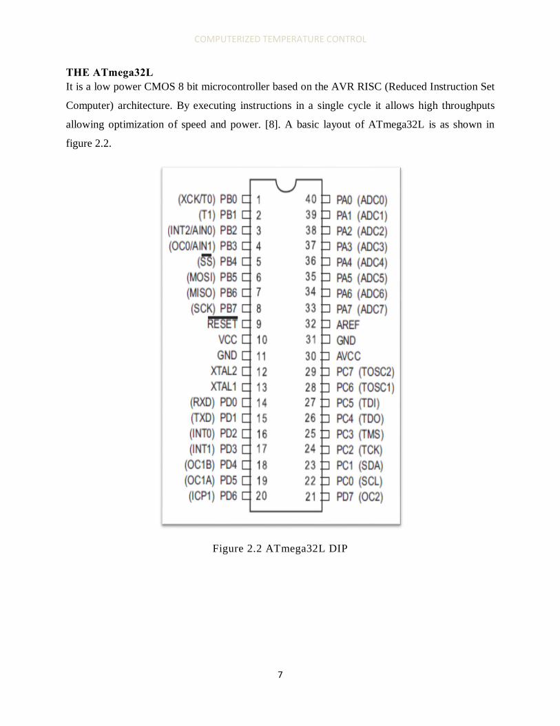
THE ATmega32L It is a low power CMOS 8 bit microcontroller based on the AVR RISC (Reduced Instruction Set
Computer) architecture. By executing instructions in a single cycle it allows high throughputs
allowing optimization of speed and power. [8]. A basic layout of ATmega32L is as shown in
figure 2.2.
Figure 2.2 ATmega32L DIP

COMPUTERIZED TEMPERATURE CONTROL
8
The primary functions of pins 1 to 40 are represented in Table 2.2
Table 2.3 pin description
Vcc Digital supply voltage.
GND Ground.
PORT A (PA7 to
PA0)
Port A serves as the analog inputs to the A/D Converter. Port A also
serves as an 8-bit bi-directional I/O port, if the A/D Converter is not
used.
PORT B
PORT C
PORT D
Port x are 8-bit bi-directional I/O port with internal pull-up resistors
(selected for each bit). The Port x output buffers have symmetrical drive
characteristics with both high sink and source capability.
RESET
Reset Input. A low level on this pin for longer than the minimum pulse
length will generate a reset, even if the clock is not running.
XTAL1 Input to the inverting Oscillator amplifier and input to the internal clock
operating circuit.
XTAL2 Output from the inverting Oscillator amplifier
AVcc The supply voltage pin for Port A and the A/D Converter. It should be
externally connected to Vcc even if the ADC is not used. If the ADC is
used, it should be connected to VCC through a low-pass filter.
AREF the analog reference pin for the A/D Converter
Pins 1 to 40 also have alternate functions as indicated on Fig 2.2. These functions are
elaborated in Appendix D.

COMPUTERIZED TEMPERATURE CONTROL
9
2.2 TEMPERATURE SENSORS A sensor is defined as a device that responds to physical conditions such as temperature,
pressure, also known as a transducers or detectors.
They following are types of temperature sensors [8]:
I. Thermistor
It is defined as a temperature sensitive resistor, with most of them having a non-linear
temperature versus resistance curve with a negative temperature coefficient.
� = ��− ��
Where K- Constant
β –temperature coefficient
T – Temperature
R - Resistance
Its main advantage is its high sensitivity, large change in resistance over a relatively small
temperature change, most useful for limit testing.
Its main disadvantage is its non linearity which makes obtaining an absolute temperature
measurement difficult.
II. Resistance Temperature Detectors (RTD)
A RTD is simply a wire that changes resistance with temperature.
R= aT + c
They suffer from self heating due to �� R losses.
RTDs are inexpensive and operate for a wide range of temperature, however they have low
sensitivity.
An example of material used is Nickel.

COMPUTERIZED TEMPERATURE CONTROL
10
III. Thermocouple
It is made by joining two dissimilar metals e.g. iron and copper. When heated the junction
produces a tiny voltage in the range of microvolt typically 40µV/⁰C. To increase sensitivity a
high gain (instrumentation) amplifier is needed.
The interface requires cold junction temperature control and curve compensation.
As the temperature is all metal high temperatures can be measured.
Its major disadvantage is its complicated interface to an electronic circuit.
IV. Silicon diode sensor
Voltage drop across a forward biased silicon diode PN junction depends on temperature,
dropping by an approximate 2mV/⁰C. A constant current source is needed to achieve this.
To increase sensitivity an amplifier of an approximate gain of 10 is used.
It can be used as a cheap, simple and accurate temperature sensor if properly designed.
V. Integrated Solid State Temperature sensor
It is based on the silicon junction temperature sensor design. An amplifier is inbuilt giving a
calibrated output, typically 10mV/⁰C, over a range of -50⁰C to 150⁰C. Accuracy +/-0.5⁰C.
It is used for general purpose low temperature sensing. It is operated from a 5V DC supply.
It has the following advantages
• Low cost
• Easy to interface
• Needs no calibration as it is done internally

COMPUTERIZED TEMPERATURE CONTROL
11
2.3 KEYPAD The keypad in this project will be used in setting the temperature range which should be
maintained by the regulatory devices. Temperature being numerical values, a numerical keypad
is preferred.
In choosing a keypad the following factors are taken into account:
• Number of pins available on the MCU for its interface
• The aesthetics of the keypad
• Minimal debounce
A numerical keypad can be implemented in two ways [2]:
2.3.1 ONE KEY ONE PIN WITH PULL UP RESISTOR This set up is more demanding with regard to the number of pins required for connection to the MCU. It also requires an extra amount of hardware in terms of resistors to be used during interfacing thereby complicating the circuit design.
2.3.2 MATRIX ENCODED KEYPAD This design is arranged in R rows and C columns, with buttons pressed to give the desired
output/number. A press on every key sets specific combination of row and columns on high or
low voltages. These outputs act as inputs into the MCU pins.
A basic 4*3 matrix keypad is illustrated by Fig2.3.
Figure 2.3 4 x 3 keypad

COMPUTERIZED TEMPERATURE CONTROL
12
2.4 DISPLAY Displays are used in electronic applications to show operating or set set values depending on the
application requirements. In this project dispalys will be used specifically for displays of set
temperatures, instructions and room temperature.
2.4.1 CATEGORIES ACCORDING TYPE OF MATERIAL a. LCD DISPLAY
In this kind of display the segments are made from Liquid Crystal(LC) hence the name LCD.
The liquid is placed between two layers of glass. LC is an organic compound that acts as an
electrically controlled light polarizer.
There are two modes of operation:
• Positive image display which turns opaque on application of voltage and its removal
causes the segment to appear lighter.
• Negative image display whose segments turn opaque when unpowered and transperent
when powered.
b. LED DISPLAY
The lighting used are Light Emmiting Diodes. These displays are cheaper compared to LCDs
but consume more power during their operation.
2.4.2 CATEGORIES ACCORDING TO TYPE OF DISPLAY PATTERN a) Seven segment display
It is named seven segment display because it has seven segments that can be switched ON and
OFF to display different english numbers.The display also has a decimal point.
Figure 2.4 seven segment display

COMPUTERIZED TEMPERATURE CONTROL
13
b) Dot matrix display
Used to display complex messages than 7 segment displays can handle. Messages include
numbers, characters and other symbols.
Each character has 5 segments or dots wide and eight segments high. The individual dots, or
segments are controlled by a controller chip.
They are in different sizes
• 1 x16 characters
• 2 x16 characters
• 2 x 20 characters
2.5 MCU HIGH POWER DEVICES INTERFACE The microcontroller ports output only provides a limited amount of current. Therefore, to drive
an output device that needs more current than this, some kind of current amplifier or switch is
needed.This is achieved through relays or current drivers.
Relays are divided into two major categories, namely:
• Electromechanical relays
• Solid - state relays
2.5.1 ELECTROMECHANICAL RELAYS (EMR) They are used for both AC and DC loads.
It consists of an NPN transistor which acts as a current drive and a switching coil, refer to
Figure 2.5. The coil requires acertain amount current to operate, greater than what the MCU can
generate. Since the MCU supllies limited current, the NPN transistor amplifies its output using
the relation
����� ∗ �
�� = �� ��
��� (��� − ���)/��

COMPUTERIZED TEMPERATURE CONTROL
14
The amplified current is used to trigger the coil.
When the coil is activated the contacts change over, completing the load circuit which operates
the load.
The relay has a diode connected across the coil, this is known as the free wheeling diode used to
protect the BJT from back EMF by forward conduction.
Figure 2.5 EMR configuration
DEMERITS OF EMR.
• It has a slow response
• Consumes large amounts of power, Voh*Icoil.
• Unreliable due to wear of the contacts.
Merits of EMR
• Low ON resistance
• High OFF resistance
• Isolation of load from control circuit.

COMPUTERIZED TEMPERATURE CONTROL
15
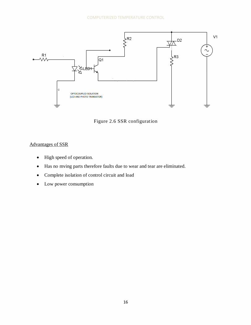
2.5.2 SOLID STATE RELAY (SSR) I t consists of [4]:
• TTL buffering,
• opto isolation and
• triac drive interface
as illustrated in Figure 2.6
All its components are semiconductor devices hence the name solid state relay.
a) TRIAC interface
The triac is basically two thyristors connected back to back, with a common gate (trigger) input,
allowing current flow in both directions. The full AC wave can then be utilised, with switching at
the same point in the positive and negative half cycles of the current.
b) Isolation
An opto – coupler is used to isolate the control system from the high voltage load circuit. It
contains of an LED and photo transistor, or thyristor, which conducts when the light from the
LED falls on its base. There is therfore no connection between the two devices and it isolates
output circuit operating at high voltage. When the MCU output is high, the opto switch is ON
and the voltage at the terminal 1 of the TRIAC is applied to the gate, turning ON the TRIAC .
It has a the following advantages:
• High speed of operation.
• Has no mving parts therefore faults due to wear and tear are eliminated.
• It is birectional therefore suitable for AC loads.
COMPUTERIZED TEMPERATURE CONTROL
16
Figure 2.6 SSR configuration
Advantages of SSR
• High speed of operation.
• Has no mving parts therefore faults due to wear and tear are eliminated.
• Complete isolation of control circuit and load
• Low power consumption

COMPUTERIZED TEMPERATURE CONTROL
17
3. SYSTEM DESIGN
3.1 SPECIFIC OBJECTIVES The specific objectives of this design include but are not limited to the following:
1. Design a MCU keypad interface that enables the user to set the desired temperature of
operation
2. Design a sensor MCU interface circuitry to allow auto detection of surroundings
temperature.
3. Create software that enables the circuit to compare the set and operating temperatures.
4. Switch on the appropriate device fan or heater depending on temperature of operation.
5. Monitor the temperatures via a PC and represent fan time and heater time graphically.
Table 3.1 represents intended design functionality
Temperature ( T) Fan Heater
T < min OFF ON
T > max ON OFF
Min < T < max OFF OFF
A basic overview of what the design is supposed to do is as illustrated in Fig3.1.
Figure 3.1 design overview illustration

COMPUTERIZED TEMPERATURE CONTROL
18
3.2 HARDWARE DESIGN Hardware design is further sub divided into the following categories:
• Temperature Sensor and MCU interface
• Keypad and MCU interface
• Display and MCU interface
• MCU choice
• Power supply design
• Fan and heater interfaces to MCU
• MCU to PC interface
3.2.1 MICROCONTROLLER CHOICE The microcontroller is the focal point of this design as it influences greatly the choice of the
other components to be used.
The following are some of the roles to be performed by the MCU.
• Amplify the sensor output signal should need be.
• Perform analogue digital conversion on the sensor output should an analogue
sensor be used.
• Compare the set temperature ranges to the operating temperatures as measured by
the sensors.
• Using a software program switch on the appropriate device depending on the
comparators outcome.
As per the intended functions, the MCU should at least posses the following:
• A built in amplifier
• An ADC
• Enough memory to accommodate the program.
• Enough pins and ports to accommodate all the devices interfaced to it.
However the amplifier and ADC need not be in built since they can be designed separately. The
end result is a design with increased hardware requirements.

COMPUTERIZED TEMPERATURE CONTROL
19
Taking all these factors into account the ATmega series is most suitable for this design.
Specifically the following:
• ATmega16/168
• ATmega8
• ATmega32/32L
All the above have the following properties useful for this design [8].
• Peripheral Features
– 8-channel, 10-bit ADC
– 8 Single-ended Channels
– Differential Channels with Programmable Gain at 1x, 10x, or 200x
– On-chip Analog Comparator
– USART (Universal Synchronous Asynchronous Receiver Transmitter)
peripheral
• Operating Voltages 4.5 - 5.5V
• Speed Grades 0 - 16 MHz
Availability playing a major the Atmega32L is chosen for this project.
3.2.2 TEMPERATURE SENSOR MCU INTERFACE The main function of the temperature sensor will be to monitor the temperature of its surroundings which are then compared to the set temperature ranges.
For a proper design of this the following design decisions need to be made:
• Choice of temperature sensor
• Appropriate interface for temperature sensor
• Number of temperature sensors to be used.

COMPUTERIZED TEMPERATURE CONTROL
20
3.2.2.1 Choice of temperature sensor In choosing a temperature sensor the following factors are taken into account:
• Range of temperature inputs
• Resolution and accuracy
• Rate of response
• Output needed (analogue or digital)
• Power supply available for sensor
As per my literature review the Integrated Solid State sensor is most suitable for this design for
the reasons listed below
• Low cost
• Easy to interface
• Needs no calibration
• High sensitivity 10mV/⁰C
• Low power consumption
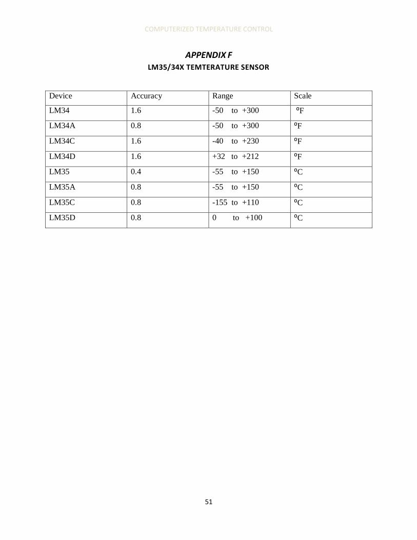
The LM35/34X series of temperature sensors offers the most variety for this design as
represented in APPENDIX F.
3.2.2.2 Temperature sensor interface The sensor MCU interface configuration is intended to minimize noise that enters the MCU and
is influenced by the following factors:
• Length of connecting cable to be used.
• Availability of in built amplifier and ADC in the MCU.
• Range for which the sensor is used for.

COMPUTERIZED TEMPERATURE CONTROL
21
The following configuration, Figure 3.2, is preferred `as per its data sheet.
Figure 3.2 LM35 connection
3.2.2.3 Number of sensors The number of temperature sensors is mainly influenced by the following:
• Size of the room
• Level of accuracy required as per users specification
• Cost
The sensors should also be evenly distributed.
3.2.3 KEYPAD MCU INTERFACE The keypad is used to set the temperature range operation.
Figure 3.3 numerical keypad
COMPUTERIZED TEMPERATURE CONTROL
22
A membrane keypad is chosen for reasons listed below:
• Low power consumption.
• Reduced errors from debounce compared to mechanical keypads.
All the rows are set to zero and columns set to one by connecting the columns to a 5V Vcc.
On pressing any key its Row and column are shorted and set to Zero, while the rest of columns
and rows are set to one. These results in a unique value for each key pressed.
The rest of its roles are software operated.
3.2.4 DISPLAY CHOICE AND MCU INTERFACE Display in this project serves the following functions:
• Show temperature set by the user
• Show operating/ room temperature
Taking into account the pros and cons of both the LED and LCD display (refer to chapter 2.), the
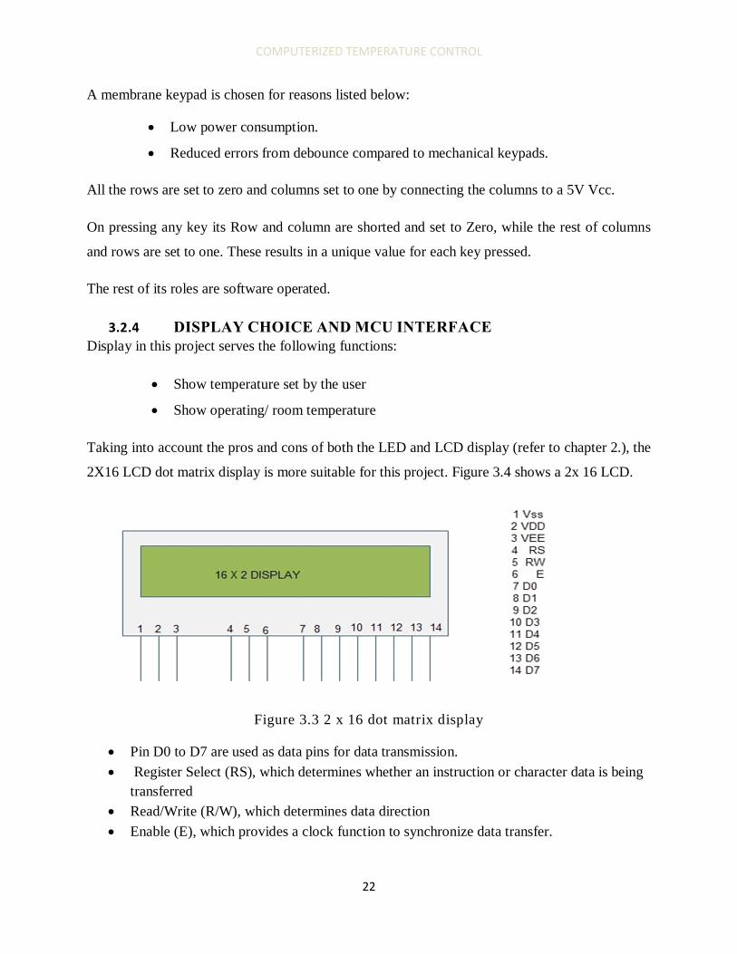
2X16 LCD dot matrix display is more suitable for this project. Figure 3.4 shows a 2x 16 LCD.
Figure 3.3 2 x 16 dot matrix display
• Pin D0 to D7 are used as data pins for data transmission. • Register Select (RS), which determines whether an instruction or character data is being
transferred • Read/Write (R/W), which determines data direction • Enable (E), which provides a clock function to synchronize data transfer.

COMPUTERIZED TEMPERATURE CONTROL
23
3.2.5 POWER SUPPLY DESIGN The design involves use of devices connected to a 5V dc supply consequently a source with this
specifications needs to be designed.
In Kenya the consumer is supplied with 240V ac phase to phase rms or 415V ac line to line rms.
This is converted to 5V dc in the following stages [4].
• Step down of supply voltage.
• Rectification of supply
• Regulation
A step- down transformer is used to step down the supply from 230V to a value slightly higher
than 5V ac, about 12VAC.
Rectification could be achieved using different configuration i.e. half wave or full wave. A full
wave rectifier is preferred as its output wave form is more accurate and has less power loss. A
bridge rectifier is used for this purpose.
A capacitor filter, C2, is used to reduce the ripples on the rectifier output before it is fed into the
regulator
A regulator/stabilizer converts the 12V output from the capacitor filter into a stable, almost
constant 5V to the circuit. Regulator in use is available in IC form, for 5V, LM7805 is preferred.
Figure 3.4 power supply design
� � ����� ���/����
Where f =Frequency, 100Hz, for full wave.
Vpp = Ripple voltage

COMPUTERIZED TEMPERATURE CONTROL
24
3.2.6 HEATER, FAN MCU INTERFACE The heater and fan are used for temperature regulation for this experiment. Being high voltage
devices relays are used to link the two to the MCU.
Relays could be SSR or EMR, taking the pros and cons of both (ref chapter 2), the SSR is most
preferred. However due to cost implications EMRs are used for this purpose. Depending on relay
rating and rating of device circuit in fig 2.5 is implemented.
3.2.7 MCU TO PC INTERFACE A proper interface is required for transmission of data from MCU to PC for graph plotting as
stated in the specific objectives
Both of these use the RS232 serial communication.
The RS232 level signal differs from normal logic signals. To interface RS232 level signals to
MCU a level Converter is needed.
A level converter, converts RS232 level signal (High=-10V LOW=+10V) from PC to TTL level
signal (HIGH=5V LOW=0V) to be fed to the MCU and also the opposite direction as figure 3.6
illustrates
Figure 3.5 level converter illustration
An I C MAX232 from maxim is used for this purpose.

COMPUTERIZED TEMPERATURE CONTROL
25
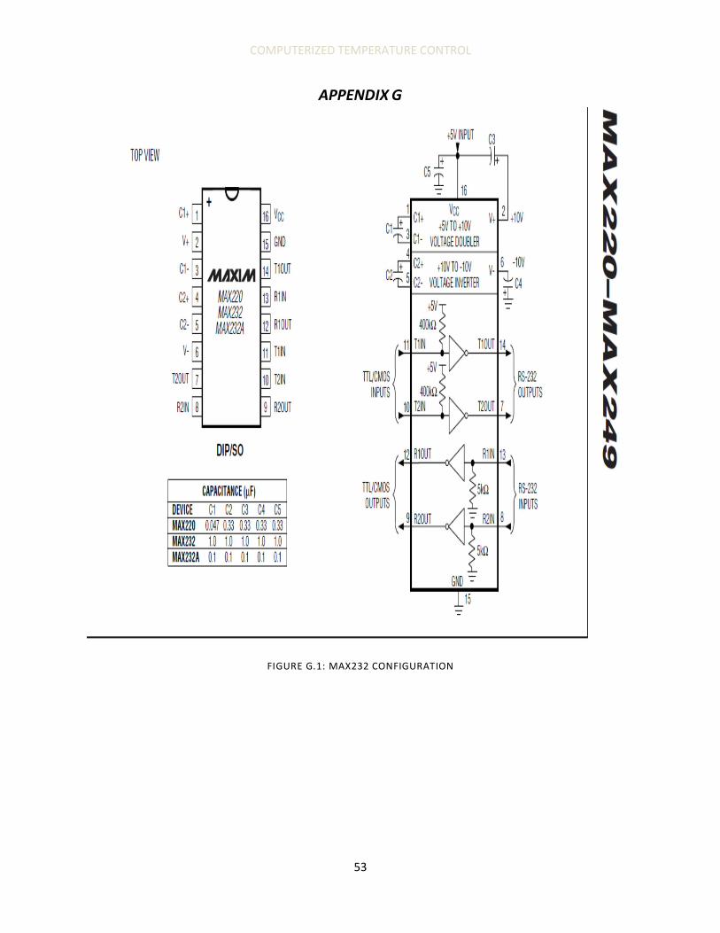
Figure 3.6 MAX232 configuration
Capacitor values are as recommended by the data sheet. APPEDIX G
C2 and C5 form a voltage doubler from Vin +5V to 10V.
C1 and C4 are used to form an inverter transforming +10V to -10V by terminal reversal of C4.

COMPUTERIZED TEMPERATURE CONTROL
26
3.3 SOFTWARE DESIGN The software design is intended to achieve the following functionalities:
• Enable user to set the desired minimum and maximum temperature
• Enable values input into the keypad to be displayed onto the LCD display
• Configure the inbuilt ADC and convert temperature sensor analogue inputs to digital
values
• Enable values of operating/ambient temperature to be displayed on the LCD display
• Compare set and operating temperatures and switch ON the appropriate regulatory
device.
• Allow PC interconnection to MCU and graph plotting of operating temperatures.
The programming language of choice being C programming language for reasons stated below:
• Project uses an AVR MCU whose IDE, AVRstudio, is open sourced.
• C programming has several predefined functions which result in a short, less complex
code compared to assembly language.
• Code compatibility, code in C can be used in other AVR microcontrollers unlike those in
assembly language which are limited to a specific MCU for which the code is written.
The software design is as illustrated in Figure 3.8 and Figure 3.9

COMPUTERIZED TEMPERATURE CONTROL
27
Figure 3.7 software design flow chart

COMPUTERIZED TEMPERATURE CONTROL
28
Figure 3.8 fan heater control subroutine

COMPUTERIZED TEMPERATURE CONTROL
29
ADC conversion
ADC= (��� *2� )/Vref
Where: N=resolution bit 10
Vin=sensor output
Vref = reference voltage of ADC
For 1⁰C LM35D gives an output of 10mV
Using 5V as the reference voltage
ADC= 2.048
Therefore 1⁰C is equivalent to approximately 2, ADC value.
The software therefore implements the formula
Temperature (t) = adc_value/2
Where: adc_value= ADC value

COMPUTERIZED TEMPERATURE CONTROL
30
4. IMPLEMENTATION AND RESULTS
4.1 HARDWARE REQUIREMENTS • ATMEGA32L • Numerical membrane keypad • LM35D temperature sensor • 16 x 2 LCD display • Relays 230VAC • DB 9 connector
4.2 SOFTWARE REQUIREMENTS • Ponyprog2000 Programmer • WINAVR • AVR STUDIO4
4.3 IMPLEMENTATION Circuit design in APPENDIX A was implemented.
Programmer board design courtesy of www.lancos.com was implemented. FIGURE A.2 APPENDIX A.
Software design in section 3.2 was the implemented in code documented in APPENDIX B. Code is written in C programming language using AVR STUDIO 4 IDE.
Program’s HEX file was the loaded into the ATMEGA 32L using Ponyprog2000 using the implemented programmers board as illustrated in FIGURES 4.1 to 4.3

COMPUTERIZED TEMPERATURE CONTROL
31
Figure 4.1 ponyprog2000 device selection
Figure 4.2 clock settings 2MHZ clock oscillator

COMPUTERIZED TEMPERATURE CONTROL
32
Figure 4.3 HEX file opened and loaded
DATA TRANSFER TO PC CONNECTION TEST
The hardware implemented for this role FIGURE 3.7 performs its intended function when tested separately using the following procedure.
1. Connect DB9 connecter to COM1 port of the PC 2. Click start>> all programs>> accessories>> communications>> HyperTerminal 3. Opened new connection and named it USART 4. Click file>>properties 5. Set baud rate at 9600, stop bit to 1, flow control to none, character size to 9 bits. 6. ASCII settings >> click on echo character 7. Any character typed on the keyboard is displayed back on the screen to test connection
However for this project the receive data option is chosen.

COMPUTERIZED TEMPERATURE CONTROL
33
4.4 RESULTS The implemented software and hardware resulted in the following functionalities as illustrated in FIGURES 4.4 to 4.8
4.4.1 KEYPAD, LCD AND TEMPERATURE SENSOR TEST
Figure 4.4 maximum settings prompt
Figure 4.5 digit2 input prompt
Figure 4.5 minimum input prompt
Figure 4.6 digit2 of minimum input prompt

COMPUTERIZED TEMPERATURE CONTROL
34
Figure 4.7 initial temperature display
Figure 4.8 display during operation
4.4.2 FAN, HEATER CONTROL SUBROUTINE TEST LEDs connected via 330 ohm resistors at PA4 and PA5 are used to test the fan and heater control subroutine
• At temperatures less than minimal set temperature LED at PA4 lights up as expected • At temperatures greater than maximum settings LED at PA5 lights up as expected. • At temperatures within maximum and minimum settings both LEDs are turned OFF.
4.4.3 TEMPERATURE VALUES TRANSFER TO PC. Even though the MAX232 interface works as expected, coming up with a proper interrupt enabled code for the transmission remains problematic. Tested code has registers configured as in APPENDIX C.

COMPUTERIZED TEMPERATURE CONTROL
35
5. RECOMMENDATION AND CONCLUSION
5.1 CONCLUSION The implemented design allows the user to set maximum and minimum temperatures, auto detects the room temperature and switches as on the appropriate regulatory device as per the test results of the Fan and heater control subroutine. These functionalities are a demonstration of successfully achieving specific objectives 1 to 4 listed in the design chapter 3, pg17.
Objective 5, transfer temperature values to PC to enable graph plotting, remains not achieved despite the hardware intended for this function giving positive results.
5.2 RECOMMENDATION The following are some of the author’s recommendations to better the functionality of this design:
a. Include a piezzo electric buzzer to allow user know if pressed key has been entered, this will enable visually impaired users use this device comfortably.
b. ATMEGA32L has 8 ADC channels that can be used to connect temperature sensors, more sensors whose values can be average gives a more accurate representation of the room temperature.

COMPUTERIZED TEMPERATURE CONTROL
36
REFERENCE [1] Stuart R. Ball, Analogue Interfacing to Embedded Microprocessors, 2nd Edition, © 2004
Elsevier Inc, Published by Newnes.
[2] Dhananjag V. Gadre, Programming and Customizing the AVR microcontroller, ©2001
The McGraw-Hill Companies, Inc, Published by McGraw Hill.
[3] Creed Huddleston, Intelligent Sensor Design, © 2007 McGraw-Hill Companies, Inc,
Published by McGraw Hill.
[4] George B. Rutkowski, Jerome E. Olesky, Solid State Electronics, 4th Edition, ©1992
McGraw-Hill Companies, Inc, Published by McGraw Hill.
[5] ATMEGA 32L datasheet.
[6] www.AVRFREAKS.com
[7] www.Lancos.com
[8] www.atmel.com/ products/microcontrollers
[9] www.WINAVR.com
COMPUTERIZED TEMPERATURE CONTROL
37
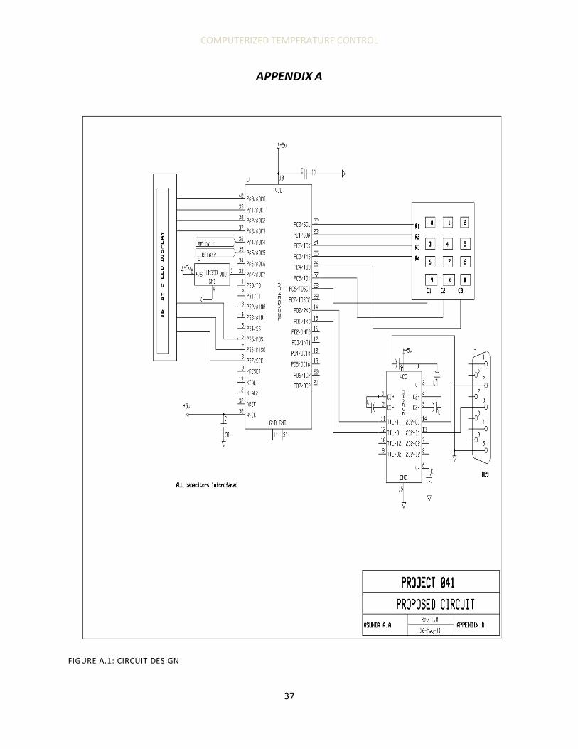
APPENDIX A
FIGURE A.1: CIRCUIT DESIGN

COMPUTERIZED TEMPERATURE CONTROL
38
FIGURE A.2: SERIAL PROGRAMMER
COMPUTERIZED TEMPERATURE CONTROL
39
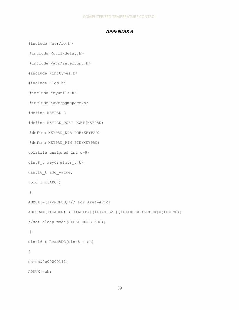
APPENDIX B
#include <avr/io.h>
#include <util/delay.h>
#include <avr/interrupt.h>
#include <inttypes.h>
#include "lcd.h"
#include "myutils.h"
#include <avr/pgmspace.h>
#define KEYPAD C
#define KEYPAD_PORT PORT(KEYPAD)
#define KEYPAD_DDR DDR(KEYPAD)
#define KEYPAD_PIN PIN(KEYPAD)
volatile unsigned int c=0;
uint8_t key0; uint8_t t;
uint16_t adc_value;
void InitADC()
{
ADMUX|=(1<<REFS0);// For Aref=AVcc;
ADCSRA=(1<<ADEN)|(1<<ADIE)|(1<<ADPS2)|(1<<ADPS0); MCUCR|=(1<<SM0);
//set_sleep_mode(SLEEP_MODE_ADC);
}
uint16_t ReadADC(uint8_t ch)
{
ch=ch&0b00000111;
ADMUX|=ch;

COMPUTERIZED TEMPERATURE CONTROL
40
//ADCSR|=(1<<ADIF);
sei();
//Start Single conversion
ADCSRA|=(1<<ADSC)|(1<<ADIE); return(ADC);
}
uint8_t GetKeyPressed()
{
uint8_t r,c;
KEYPAD_PORT|= 0X0F;
for(c=0;c<3;c++)
{
KEYPAD_DDR&=~(0X7F);
KEYPAD_DDR|=(0X40>>c);
for(r=0;r<4;r++)
{
if(!(KEYPAD_PIN & (0X08>>r)))
{ while(1)
{
return (r*3+c);
}
}
return 255;
}
void main()
{
uint8_t i;
COMPUTERIZED TEMPERATURE CONTROL
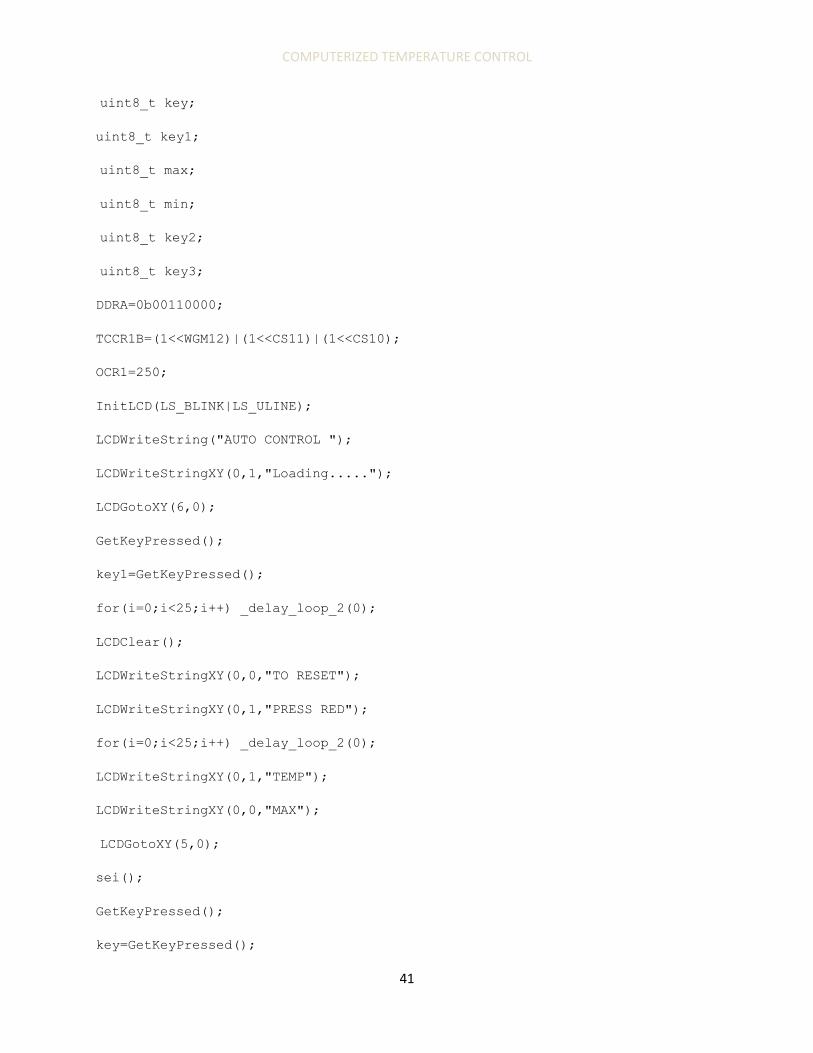
41
uint8_t key;
uint8_t key1;
uint8_t max;
uint8_t min;
uint8_t key2;
uint8_t key3;
DDRA=0b00110000;
TCCR1B=(1<<WGM12)|(1<<CS11)|(1<<CS10);
OCR1=250;
InitLCD(LS_BLINK|LS_ULINE);
LCDWriteString("AUTO CONTROL ");
LCDWriteStringXY(0,1,"Loading.....");
LCDGotoXY(6,0);
GetKeyPressed();
key1=GetKeyPressed();
for(i=0;i<25;i++) _delay_loop_2(0);
LCDClear();
LCDWriteStringXY(0,0,"TO RESET");
LCDWriteStringXY(0,1,"PRESS RED");
for(i=0;i<25;i++) _delay_loop_2(0);
LCDWriteStringXY(0,1,"TEMP");
LCDWriteStringXY(0,0,"MAX");
LCDGotoXY(5,0);
sei();
GetKeyPressed();
key=GetKeyPressed();
COMPUTERIZED TEMPERATURE CONTROL
42
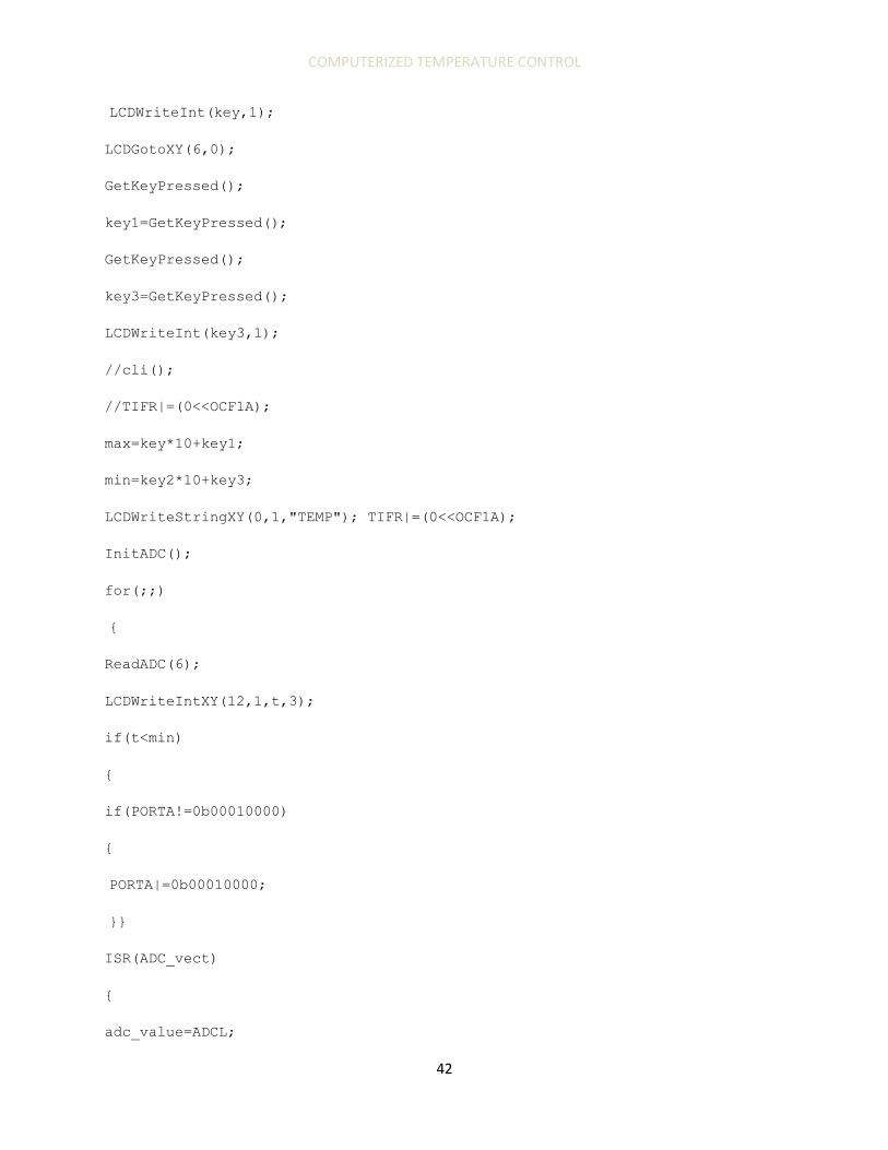
LCDWriteInt(key,1);
LCDGotoXY(6,0);
GetKeyPressed();
key1=GetKeyPressed();
GetKeyPressed();
key3=GetKeyPressed();
LCDWriteInt(key3,1);
//cli();
//TIFR|=(0<<OCF1A);
max=key*10+key1;
min=key2*10+key3;
LCDWriteStringXY(0,1,"TEMP"); TIFR|=(0<<OCF1A);
InitADC();
for(;;)
{
ReadADC(6);
LCDWriteIntXY(12,1,t,3);
if(t<min)
{
if(PORTA!=0b00010000)
{
PORTA|=0b00010000;
}}
ISR(ADC_vect)
{
adc_value=ADCL;

COMPUTERIZED TEMPERATURE CONTROL
43
adc_value+=(ADCH<<8);
ISR(TIMER1_COMPA_vect)
{
for(;;)
{
c++;
if(GetKeyPressed()!=255)
{
key0=GetKeyPressed();
if (c==60,000)
t=adc_value/2;
break;
} else
{
}
}

COMPUTERIZED TEMPERATURE CONTROL
44
APPENDIX C DETAILED REGISTER SETTINGS REVIEW
1 ADC OF TEMPERATURE SENSOR SIGNAL ADC involves a proper configuration of the following:
a. ADC Prescaler
ADC operates at frequencies between 50 KHz and 200KHz. High frequencies are faster but less
accurate compared to lower frequencies. The prescaler is set to provide acceptable frequency for
ADC from any clock system. The system clock can be divided by upto 128 in multiples of 2.
ADC frequency = ���� /���������
A frequency of 62.5 KHz using an external 2MHz external clock signal.
Prescaler = ���� / ����
= 2000000/62.5OOO
=32
Prescaler is set to 32.
This is done by configuring the ADCSRA (ADC Control Status Register A) used to set the status
of the ADC and control it.
TABLE C.1: ADCSRA
Bit No 7 6 5 4 3 2 1 0
Bit Name ADEN ADSC ADATE ADIF ADIE ADPS2 ADPS1 ADPSO
Initial
value
0 0 0 0 0 0 0 0
Set Value 1 1 0 1 0 1 0 1
ADEN – set to 1 to enable ADC
ADSC – set to 1 to do conversion

COMPUTERIZED TEMPERATURE CONTROL
45
ADIF – interruption set 1 by hardware when conversion is complete.
TABLE C.2: PRESCALER DIVISION FACTOR SETTINGS
ADPS2 ADPS1 ADPSO Division Factor
1 0 1 32
1 1 0 64
ADCSRA = (1<<ADEN)|(1<<ADPS2)|(ADPS1);
b. ADC Power supply
ADC requires a power source to act as the REF voltage. Two options:
Ø ARef 2.56V which is internal.
Ø AVcc supplied by an external 5V supply.
AVcc operates at 5V; higher voltage improves accuracy of ADC values.
This is achieved by configuring the ADMUX register
TABLE C.3: ADMUX REGISTER
Bit No 7 6 5 4 3 2 1 0
Bit name REFS1 REFS0 ADLAR MUX4 MUX3 MUX2 MUX1 MUX0
Initial
value
0 0 0 0 0 0 0 0
Table c.4: Vref selection
REFS1 REFS0 VRef selected
0 0 ARef
0 1 AVcc

COMPUTERIZED TEMPERATURE CONTROL
46
2 PC, MCU INTERFACE Operation of this interface relies on configuration of the following registers
Ø UDR- USART Data Register
Ø UCSR- USART Control and Status Register
Ø UBRR- USART Baud Rate Register
a. UCSRA
TABLE C.5: UCSRA
BIT No 7 6 5 4 3 2 1
BIT
Name
RXC TXC UBRE FE DOR PE U2X
Initial
value
0 0 1 0 0 0 0
RXC- set to one upon complete receiving of data
TXC – set to one upon complete transmission
b. UCSRB
TABLE C.5: UCSRB
BIT No 7 6 5 4 3 2 1
BIT
Name
RXCIE TXCIE UDRIE RXEN TXEN UCS2Z RXB8
Initial
Value
0 0 0 0 0 0 0
RXCIE – enabled when set to 1, Receive Complete interrupt
TXCIE – enabled when set to one, Transmission Enabled Interrupt
TXEN – Transmission Enable
RXEN – Receive Enable
COMPUTERIZED TEMPERATURE CONTROL
47
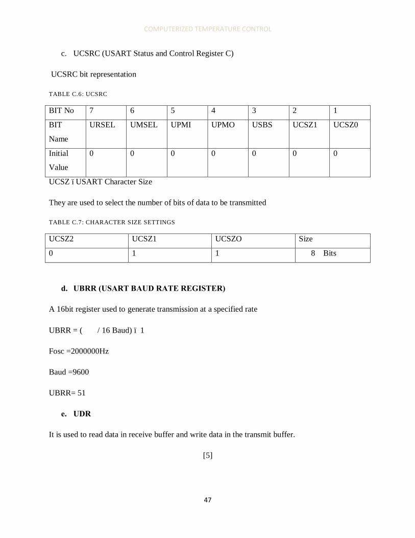
c. UCSRC (USART Status and Control Register C)
UCSRC bit representation
TABLE C.6: UCSRC
BIT No 7 6 5 4 3 2 1
BIT
Name
URSEL UMSEL UPMI UPMO USBS UCSZ1 UCSZ0
Initial
Value
0 0 0 0 0 0 0
UCSZ –USART Character Size
They are used to select the number of bits of data to be transmitted
TABLE C.7: CHARACTER SIZE SETTINGS
UCSZ2 UCSZ1 UCSZO Size
0 1 1 8 Bits
d. UBRR (USART BAUD RATE REGISTER)
A 16bit register used to generate transmission at a specified rate
UBRR = ( ����/ 16 Baud) – 1
Fosc =2000000Hz
Baud =9600
UBRR= 51
e. UDR
It is used to read data in receive buffer and write data in the transmit buffer.
[5]
COMPUTERIZED TEMPERATURE CONTROL
48
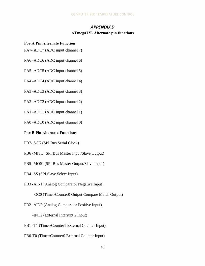
APPENDIX D ATmega32L Alternate pin functions
PortA Pin Alternate Function
PA7- ADC7 (ADC input channel 7)
PA6 -ADC6 (ADC input channel 6)
PA5 -ADC5 (ADC input channel 5)
PA4 -ADC4 (ADC input channel 4)
PA3 -ADC3 (ADC input channel 3)
PA2 -ADC2 (ADC input channel 2)
PA1 -ADC1 (ADC input channel 1)
PA0 -ADC0 (ADC input channel 0)
PortB Pin Alternate Functions
PB7- SCK (SPI Bus Serial Clock)
PB6 -MISO (SPI Bus Master Input/Slave Output)
PB5 -MOSI (SPI Bus Master Output/Slave Input)
PB4 -SS (SPI Slave Select Input)
PB3 -AIN1 (Analog Comparator Negative Input)
OC0 (Timer/Counter0 Output Compare Match Output)
PB2- AIN0 (Analog Comparator Positive Input)
-INT2 (External Interrupt 2 Input)
PB1 -T1 (Timer/Counter1 External Counter Input)
PB0-T0 (Timer/Counter0 External Counter Input)
COMPUTERIZED TEMPERATURE CONTROL
49
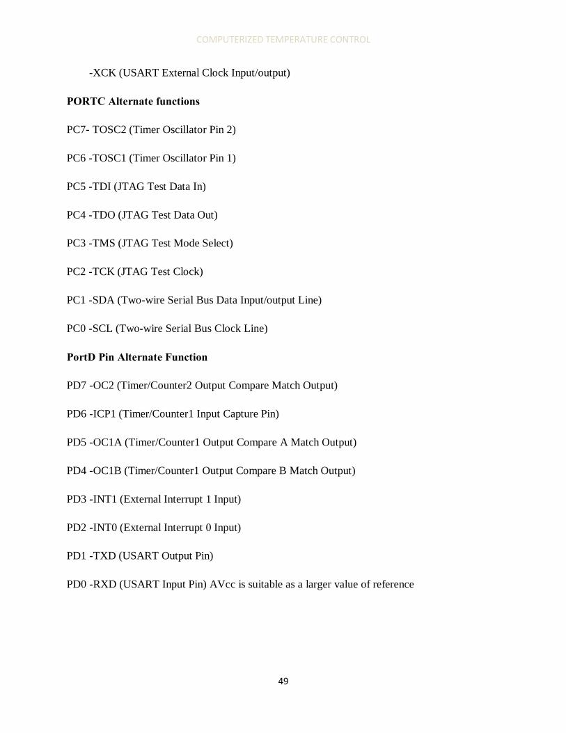
-XCK (USART External Clock Input/output)
PORTC Alternate functions
PC7- TOSC2 (Timer Oscillator Pin 2)
PC6 -TOSC1 (Timer Oscillator Pin 1)
PC5 -TDI (JTAG Test Data In)
PC4 -TDO (JTAG Test Data Out)
PC3 -TMS (JTAG Test Mode Select)
PC2 -TCK (JTAG Test Clock)
PC1 -SDA (Two-wire Serial Bus Data Input/output Line)
PC0 -SCL (Two-wire Serial Bus Clock Line)
PortD Pin Alternate Function
PD7 -OC2 (Timer/Counter2 Output Compare Match Output)
PD6 -ICP1 (Timer/Counter1 Input Capture Pin)
PD5 -OC1A (Timer/Counter1 Output Compare A Match Output)
PD4 -OC1B (Timer/Counter1 Output Compare B Match Output)
PD3 -INT1 (External Interrupt 1 Input)
PD2 -INT0 (External Interrupt 0 Input)
PD1 -TXD (USART Output Pin)
PD0 -RXD (USART Input Pin) AVcc is suitable as a larger value of reference

COMPUTERIZED TEMPERATURE CONTROL
50
APPENDIX E LCD DISPLAY
The proposed LCD display is the 16 X 2, HD447804 manufactured by Hitachi.
FIGURE E.1: LCD INITIALIZATION
FIGURE E.2: LCD PIN DESCRIPTION
COMPUTERIZED TEMPERATURE CONTROL
51
APPENDIX F LM35/34X TEMTERATURE SENSOR
Device Accuracy Range Scale
LM34 1.6 -50 to +300 ⁰F
LM34A 0.8 -50 to +300 ⁰F
LM34C 1.6 -40 to +230 ⁰F
LM34D 1.6 +32 to +212 ⁰F
LM35 0.4 -55 to +150 ⁰C
LM35A 0.8 -55 to +150 ⁰C
LM35C 0.8 -155 to +110 ⁰C
LM35D 0.8 0 to +100 ⁰C

COMPUTERIZED TEMPERATURE CONTROL
52
COMPUTERIZED TEMPERATURE CONTROL
53
APPENDIX G
FIGURE G.1: MAX232 CONFIGURATION