computer organization architecture -...
TRANSCRIPT

Computer Organization
&
Architecture
For
Computer Science &
Information Technology
By
www.thegateacademy.com

Syllabus
: 080-617 66 222, [email protected] ©Copyright reserved. Web:www.thegateacademy.com
Syllabus for
Computer Organization and Architecture
Machine Instructions and Addressing Modes, ALU, Data‐Path and Control Unit, Instruction
Pipelining, Memory Hierarchy, Cache, Main Memory and Secondary Storage, I/O Interface (Interrupt
and DMA Mode).
Analysis of GATE Papers
Year Percentage of Marks Overall Percentage
2015 5.00
8.6%
2014 6.66
2013 11.00
2012 6.00
2011 7.00
2010 9.00
2009 6.66
2008 16.00
2007 9.33
2006 9.33

Contents
:080-617 66 222, [email protected] ©Copyright reserved.Web:www.thegateacademy.com i
Contents
Chapters Page No.
#1. Introduction 1 – 39
Computer Architecture 1
Computer Organization 1
Computer Design 1 – 4
Positional Numbering Systems 4 – 8
Binary Data Representation 8 – 12
Hamming Codes 12 – 15
Booth’s Algorithm 15 – 25
CPU Design 25 – 26
Binary Adder 27 – 32
Arithmetic Logic Unit (ALU) 32 – 35
Assignment 1 36
Assignment 2 36 – 38
Answer Keys & Explanations 38 – 39
#2. Memory Hierarchy 40 – 65
Introduction 40
Memory Parameter 40 – 41
Main Memory 42 – 46
Cache Memory 46 – 51
Virtual Memory 52 – 54
Solved Examples 55
Assignment 1 56 – 58
Assignment 2 58 – 61
Answer Keys & Explanations 61 – 65
#3. Pipelining and Vector Processing 66 – 84
Parallel Processing 66 – 70
Pipelining 70 – 76
Hardware Technique 76
Software Technique 76 – 78
Solved Example 78
Assignment 1 79 – 80
Assignment 2 80 – 81
Answer Keys & Explanations 82 – 84

Contents
:080-617 66 222, [email protected] ©Copyright reserved.Web:www.thegateacademy.com ii
#4. Instruction Set and Addressing Mode 85 – 97 Introduction 85
Instruction format 85 – 88
Addressing Modes 88 – 89
CISC and RISC 90 – 91
Assignment 1 92 – 94
Assignment 2 94 – 95
Answer Keys & Explanations 95 – 97
#5. CPU Operation and Design 98 – 107 CPU Operations 98 – 101
Data Path and Control Path 101 – 102
Machine Cycle 102 – 105
Assignment 106 – 107
Answer Keys & Explanations 107
#6. I/O Interface (Interrupt and DMA Mode) 108 – 123 Introduction 108
Difference Between the Computer and Peripheral Devices 108
I/O Bus and Interface Modules 109
I/O Bus and Memory Bus 109
Modes of Data Transfer 110 – 113
I/O Communication Technique 113
Programmed I/O 113 – 114
Interrupt Driven I/O 114 – 115
Direct Memory Access (DMA) 115 – 116
Multi-Cycle Transfer 116 – 119
Assignment 120 – 122
Answer Keys & Explanations 122 – 123
#7. Control Unit Design 124 – 131 Von-Neumann Architecture 124 – 125
Von-Neumann Bottleneck 125 – 126
Harvard Architecture 126
Control Unit 126 – 129
Solved Examples 129
Assignment 130
Answer Keys & Explanations 131
Module Test 132 – 141 Test Questions 132 – 137
Answer Keys & Explanations 138 – 141
Reference Books 142

:080-617 66 222, [email protected] ©Copyright reserved. Web:www.thegateacademy.com 1
“The best way to predict your future is to create it.”
…..Abraham Lincoln
Introduction
Learning Objectives After reading this chapter, you will know:
1. Computer Architecture
2. Computer Organization
3. Computer Design
4. Positional Numbering Systems
5. Binary Data Representation
6. Hamming Codes
7. Booth’s Algorithm
8. CPU Design
9. Binary Adder
10. Arithmetic Logic Unit (ALU)
Computer Architecture Computer architecture deals with the structure and behavior of the computer system. It includes the
information formats, the instruction set and the hardware units that implement the instructions
along with the techniques for addressing memory.
Computer Organization Computer organization deals with the way the various hardware components operate and the way
they are connected together to form the computer system. It also deals with the units of the
computer that receive information from external sources and send computed results to external
destinations.
Computer Design Computer design is concerned with the hardware design of the computer. This aspect of computer
hardware is sometimes referred to as computer implementation. Figure. Shows in the below basic
building blocks of a typical computer system.
MEMORY
INPUT OUTPUT ALU
CPU
CU
Basic Functional Units of a Computer
1
CH
AP
TE
R

Introduction
: 080-617 66 222, [email protected] ©Copyright reserved. Web:www.thegateacademy.com 2
The basic blocks available in any digital computer are, Arithmetic Logic Unit (ALU), Control
Unit, Memory and Input/Output Unit.
Input Unit
It is a medium of communication between the user and the computer. With the help of input
units only, it is possible to enter programs and data to the computer.
E.g.: Keyboard, floppy disk drive, hard disk drive, mouse, Magnetic Ink Character Recognition
(MICR), Optical Character Recognition (OCR), paper tape reader, Magnetic tape reader, Scanner
etc. Joy stick,
Output Unit
It is a medium of communication between the computer and the user. With the help of output
units only, it is possible to get results from the computer.
Example: Printers, Video Display Unit (VDU), Floppy disk drive, Hard disk drive, Magnetic tape
drive, punched cards, paper tape, plotter, digitizer etc.
Memory: The memory unit is responsible for storing the user programs and data. The digital
computer memory unit mainly consists of two types of memories: Read Only Memory (ROM) and
Read Write Memory (R/WM) or Random Access Memory (RAM).
ROM
ROM is used to store permanent programs or system programs. It does not have write
capability.
Types: PROM, EPROM, EEPROM
RAM
It is also called user memory because the user programs or application programs are stored in
this memory. The CPU is able to write or read information into or from this type of memory.
Types: static, dynamic, scratch pad etc.
Central Processing Unit (CPU)
The ALU and Control Unit together are called CPU. It is the heart of any digital computer.
ALU (Arithmetic Logic Unit)
The data processing part of CPU is responsible for executing arithmetic and logical instructions on
various operand types including fixed point and floating point numbers.
Various circuits used to execute data processing instructions are usually combined in a single circuit
called an arithmetic logic unit (ALU). The complexity of an ALU is determined by the way in which
its arithmetic instructions are realized. Simple ALU’s those perform fixed point addition and
subtraction as well as word based logical operations, can be realized by combinational circuits.
Much more extensive data processing and control logic are necessary to implement is floating point
arithmetic in hardware.

Introduction
: 080-617 66 222, [email protected] ©Copyright reserved. Web:www.thegateacademy.com 3
Example: For finding the sum of a series x = y × 2 + y × 4 + y × 8 + ………+ y × 128, how will
you use an ALU without a multiplier unit but with an adder and barrel shifter? Barrel
shifter is a shifter that does n − bit shift in one clock cycle.
Solution: Left shift by 7 means multiplication by 128,6 means multiplication by 64,5 means
multiplication by 32, ……… and 1 means multiplication by2. Hence the shift operations
will be faster for computing. Using the barrel shifter seven times for shifting by 1,2,3,4 …..,
we find and store left shifted values of 𝑦 in a register and add these values.
Two Types of ALUs
1. Combinational ALUs
The simple ALU combine the functions of 2’s complement adder-subtracter with those of a
circuit that generates word based logic functions of the form f(x, y).
For example AND, XOR and NOT. They can thus implement most of a CPU’s fixed point data
processing instructions.
2. Sequential ALU’s
Both multiplication and division can be implemented by combinational logic. It is generally
impractical to merge these operations with addition and subtraction into a single,
combinational ALU.
The combinational multipliers and dividers are costly in terms of hardware. They are also much
slower than addition and subtraction.
An n-bit combinational multiplier or divider is typically composed of n or more levels of add-
subtract logic, making multiplication and division at least ‘n’ times slower than addition (or)
subtraction, where addition and subtraction each takes one clock cycle, while multiplication and
division are multicycle operations.
Example: How many 16-bit ALU slices can be used for designing a 64-bit ALU?
Solution: Four slices will be needed in parallel if ALU 64-bits operations are to take nearly the same
time as 16-bit slice, and four slices will be needed in series if ALU 64- bits operations are
to take nearly four times of 16-bit slice.
Interconnection of Basic of Blocks
In order to form an operational system individual components or parts of computer that we have
discussed need to be connected in some organized way, for this purpose, ‘bus’ is introduced which is
defined as a group of lines that serves as a connecting path for several devices. These lines carry
data, address and control signals. Figure. Shows in the below exemplanary interconnection using
single bus structure
Output Memory CPU
Single-Bus Structure
Input
Introduction
: 080-617 66 222, [email protected] ©Copyright reserved. Web:www.thegateacademy.com 4
Since, this bus can be used only for single transfer at a time multiple buses are introduced so as to
achieve more concurrency in operations so that two or more transfers can be carried out at the
same time. Hereby, increasing performance but at an increased cost.
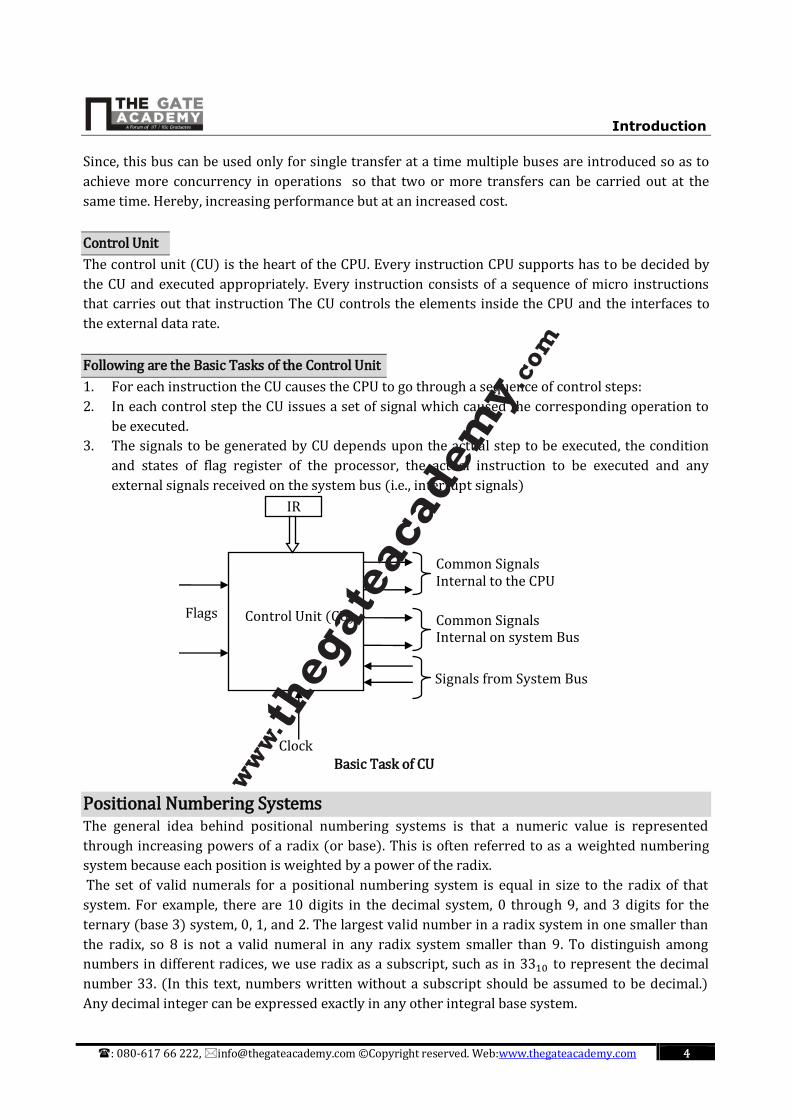
Control Unit
The control unit (CU) is the heart of the CPU. Every instruction CPU supports has to be decided by
the CU and executed appropriately. Every instruction consists of a sequence of micro instructions
that carries out that instruction The CU controls the elements inside the CPU and the interfaces to
the external data rate.
Following are the Basic Tasks of the Control Unit
1. For each instruction the CU causes the CPU to go through a sequence of control steps:
2. In each control step the CU issues a set of signal which caused the corresponding operation to
be executed.
3. The signals to be generated by CU depends upon the actual step to be executed, the condition
and states of flag register of the processor, the actual instruction to be executed and any
external signals received on the system bus (i.e., interrupt signals)
Basic Task of CU
Positional Numbering Systems The general idea behind positional numbering systems is that a numeric value is represented
through increasing powers of a radix (or base). This is often referred to as a weighted numbering
system because each position is weighted by a power of the radix.
The set of valid numerals for a positional numbering system is equal in size to the radix of that
system. For example, there are 10 digits in the decimal system, 0 through 9, and 3 digits for the
ternary (base 3) system, 0, 1, and 2. The largest valid number in a radix system in one smaller than
the radix, so 8 is not a valid numeral in any radix system smaller than 9. To distinguish among
numbers in different radices, we use radix as a subscript, such as in 3310 to represent the decimal
number 33. (In this text, numbers written without a subscript should be assumed to be decimal.)
Any decimal integer can be expressed exactly in any other integral base system.
IR
Common Signals Internal to the CPU
Common Signals Internal on system Bus
Signals from System Bus
Control Unit (CU)
Clock
Flags

Introduction
: 080-617 66 222, [email protected] ©Copyright reserved. Web:www.thegateacademy.com 5
Example: Three numbers represented as powers of a radix.
243.5110 = 2 × 10² + 4 × 101 + 3 × 100 + 5 × 10⁻¹ + 1 × 10⁻²
2123 = 2 × 32 + 1 × 31 + 2 × 30 = 2310
101102 = 1 × 24 + 0 × 231 × 22 + 1 × 21 + 0 × 20 = 2210
The two most important radices in computer science are binary (base two), and
hexadecimal (base 16). Another radix of interest is octal (base 8). The binary system uses
only the digits 0 and 1; the octal system, 0 through 7. The hexadecimal system allows the
digits 0 thought 9 with A, B, C, D, E, and F being used to represent the numbers 10
through 15.
Powers of 2 Decimal 4-Bit Binary Hexadecimal
2−2 =1
4= 0.25
0 0000 0
2−1 =1
2= 0.5
1 0001 1
20 = 1 2 0010 2
21 = 2 3 0011 3
22 = 4 4 0100 4
23 = 8 5 0101 5
24 = 16 6 0110 6
25 = 32 7 0111 7
26 = 64 8 1000 8
27 = 128 9 1001 9 28 = 256 10 1010 A
29 = 512 11 1011 B
210 = 1024 12 1100 C
215 = 32,768 13 1101 D
216 = 65,536 14 1110 E 15 1111 F
Some Numbers to Remember
Converting Unsigned Whole Numbers
We begin with the base conversion of unsigned numbers. Conversion of signed numbers (numbers
that can be positive or negative) is more complex, and it is important that you first understand the
basic technique for conversion before continuing with signed numbers.
Conversion between base systems can be done by using either repeated subtraction or a division-
remainder method. The subtraction method is cumbersome and requires a familiarity with the
powers of the radix being used, because it the more intuitive of the two methods, however, we will
explain it first.
As an example, let’s say we want to convert 10410 to base 3. We know that 34 = 81 is the highest
power of 3 that is less than 104, so our base 3 number will be 5 digits wide (one for each power of
the radix: 0 through 4). We make note that 81 goes once into 104 and subtract, leaving a difference
of 23. We know that the next power of 3, 33 = 27, is too large to subtract, so we note the zero.
“Placeholder” and look for how many times 32 = 9 divides 23. We see that it goes twice and subtract
18. We are left with 5, from which we subtract 31 = 3, leaving 2, which is 2 × 30.

Introduction
: 080-617 66 222, [email protected] ©Copyright reserved. Web:www.thegateacademy.com 6
Example:
Convert 10410 to base 3 using subtraction. 104−81
23
= 34 × 1
−0
23= 33 × 0
−18
5= 32 × 2
−3
2= 31 × 1
−2
0= 30 × 2
10410 = 102123
The division-remainder method is faster and easier than the repeated subtraction
method. It employs the idea that successive division by the base are in fact successive
subtractions by powers of the base. The remainders that we get when we sequentially
divide by the base end up being the digits of the result, which are read from bottom to
top.
Example:
Convert 14710 to binary. 2 ÷ 147 1 2 Divides 147 73 times with a remainder of 1 2 ÷ 73 1 2 Divides 73 76 times with a remainder of 1 2 ÷ 36 0 2 Divides 36 18 times with a remainder of 0 2 ÷ 18 0 2 Divides 18 9 times with a remainder of 0 2 ÷ 9 1 2 Divides 9 4 times with a remainder of 1 2 ÷ 4 1 2 Divides 4 2 times with a remainder of 0 2 ÷ 2 1 2 Divides 2 1 times with a remainder of 0 2 ÷ 1 1 2 Divides 1 0 times with a remainder of 1 0
Reading the remainders from bottom to top, we have: 14710 = 100100112 .
A binary number with N bits can represent unsigned integers from 0 to2N − 1. For
example, 4 bits can represent the decimal values 0 through 15, whereas 8 bits can
represent the values 0 through 255. The range of values that can be represented by a
given number of bits is extremely important when doing arithmetic operations on binary
numbers. Consider a situation in which binary numbers are 4 bits in length, and we wish
to add11112 . (1510) to11112 . We know that 15 plus 15 is 30, but 30 cannot be
represented using only 4 bits. This is an example of a condition known as overflow, which
occurs in unsigned binary representation when the result of an arithmetic operation is
outside the range of allowable precision for the given number of bits..