computer graphics - bilgisayar mühendisliği...
TRANSCRIPT
Computer Graphics: Two Dimensional Viewing
Clipping and Normalized Window
By: A. H. Abdul Hafez
April 17, 2017 1 CG, by Dr. A.H. Abdul Hafez, CE Dept. HKU
Outlines
April 17, 2017 CG, by Dr. A.H. Abdul Hafez, CE Dept. HKU 2
1. End
Transformation between 2 coordinate systems
April 17, 2017 CG, by Dr. A.H. Abdul Hafez, CE Dept. HKU 3
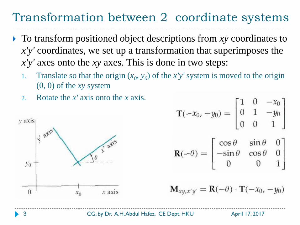
To transform positioned object descriptions from xy coordinates to
x'y' coordinates, we set up a transformation that superimposes the
x'y' axes onto the xy axes. This is done in two steps:
1. Translate so that the origin (x0, y0) of the x'y' system is moved to the origin
(0, 0) of the xy system
2. Rotate the x' axis onto the x axis.

Transformation between 2 coordinate systems
April 17, 2017 CG, by Dr. A.H. Abdul Hafez, CE Dept. HKU 4
Specify a vector V that indicates the direction for the positive y'
axis
And we obtain the unit vector u along the x' axis by applying a 90o
clockwise rotation to vector v:
Example:

2D viewing pipeline
April 17, 2017 CG, by Dr. A.H. Abdul Hafez, CE Dept. HKU 5
A clipping window is the section of a two-dimensional scene that
is selected for display, because all parts of the scene outside the
selected section are "clipped” off.
Sometimes the clipping window is alluded to as the world window
or the viewing window.
Graphics packages also allow us to control the placement within
the display window using another "window" called the viewport.
Objects inside the clipping window are mapped to the viewport,
and it is the viewport that is then positioned within the display
window.
2D viewing pipeline
April 17, 2017 CG, by Dr. A.H. Abdul Hafez, CE Dept. HKU 6
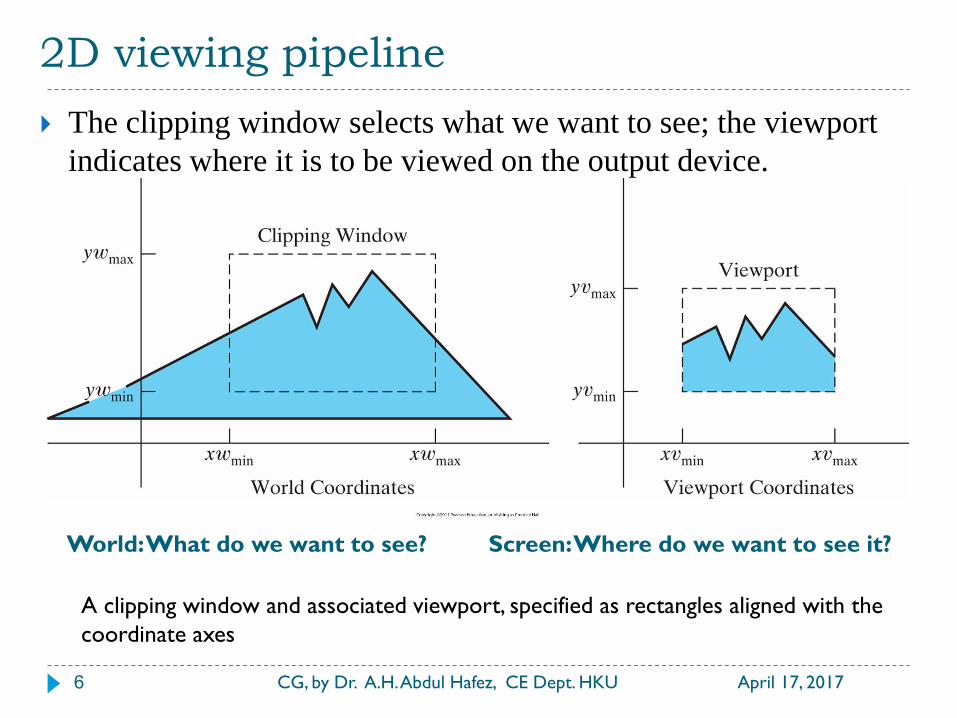
The clipping window selects what we want to see; the viewport
indicates where it is to be viewed on the output device.
World: What do we want to see? Screen: Where do we want to see it?
A clipping window and associated viewport, specified as rectangles aligned with the
coordinate axes
2D viewing pipeline
April 17, 2017 CG, by Dr. A.H. Abdul Hafez, CE Dept. HKU 7
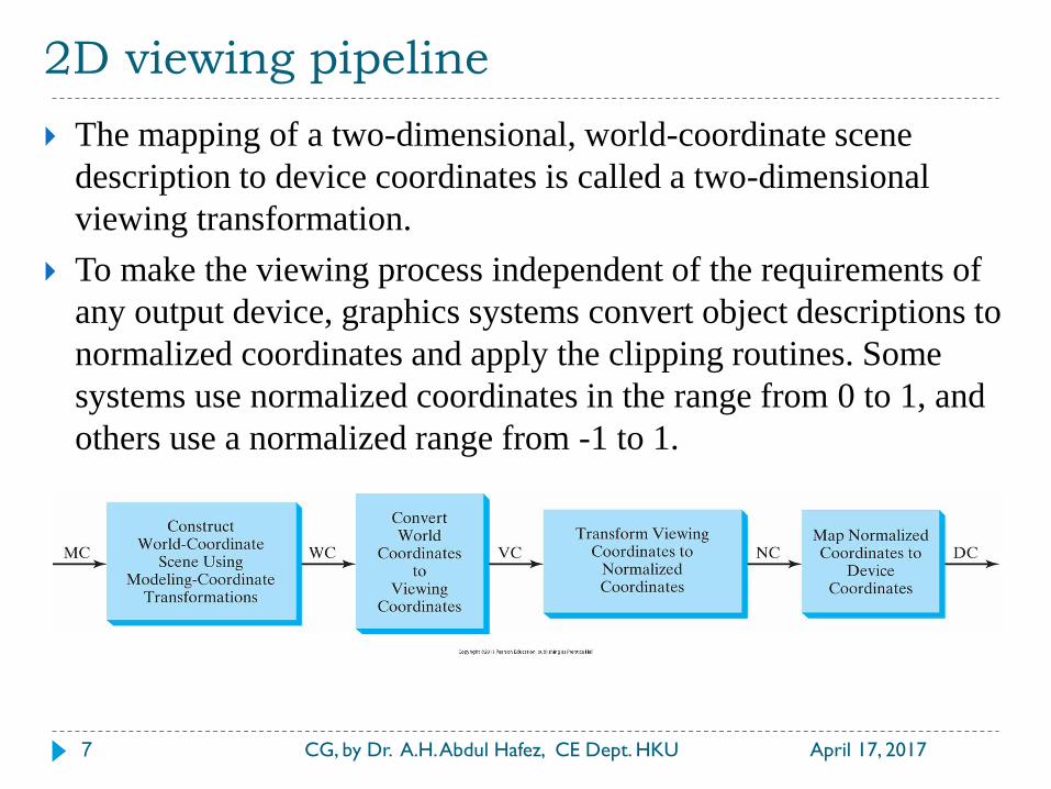
The mapping of a two-dimensional, world-coordinate scene
description to device coordinates is called a two-dimensional
viewing transformation.
To make the viewing process independent of the requirements of
any output device, graphics systems convert object descriptions to
normalized coordinates and apply the clipping routines. Some
systems use normalized coordinates in the range from 0 to 1, and
others use a normalized range from -1 to 1.
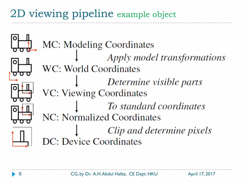
2D viewing pipeline example object
April 17, 2017 CG, by Dr. A.H. Abdul Hafez, CE Dept. HKU 8

Viewing-coordinate clipping Window
April 17, 2017 CG, by Dr. A.H. Abdul Hafez, CE Dept. HKU 9
A viewing-coordinate frame is moved into coincidence with the world frame by
a) applying a translation matrix T to move the viewing origin to the world
origin, then
b) applying a rotation matrix R to align the axes of the two systems.
Viewport Transformation scale and translate
April 17, 2017 CG, by Dr. A.H. Abdul Hafez, CE Dept. HKU 10
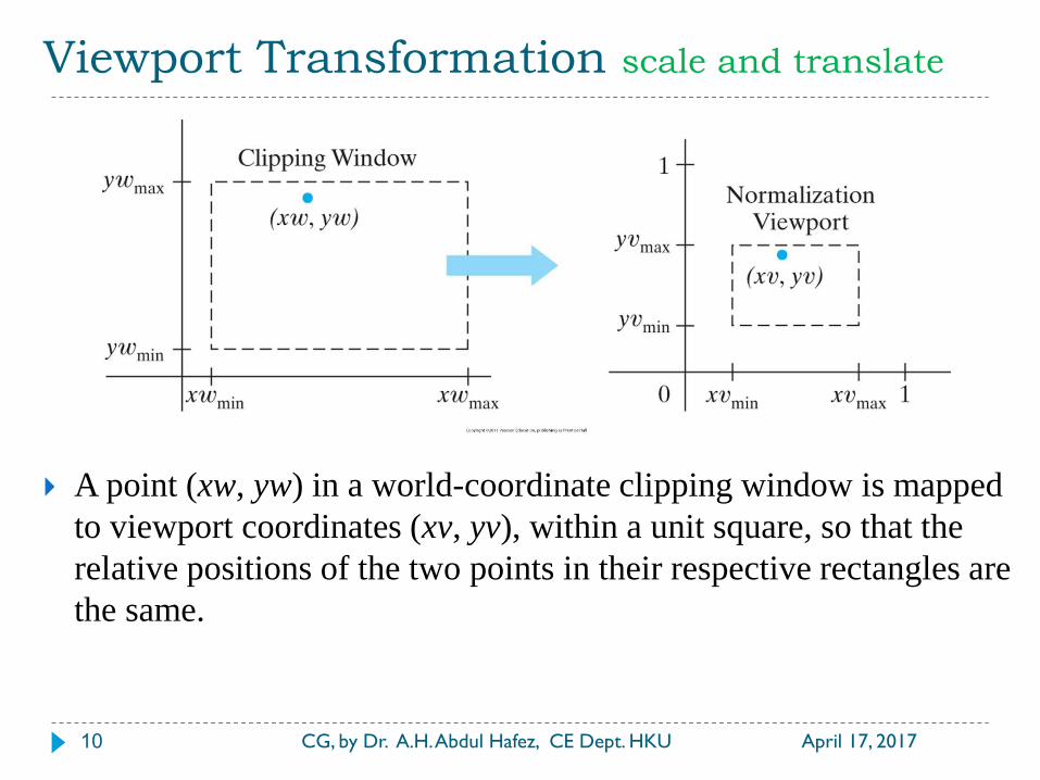
A point (xw, yw) in a world-coordinate clipping window is mapped
to viewport coordinates (xv, yv), within a unit square, so that the
relative positions of the two points in their respective rectangles are
the same.
Viewport Transformation scale and translate
April 17, 2017 CG, by Dr. A.H. Abdul Hafez, CE Dept. HKU 11
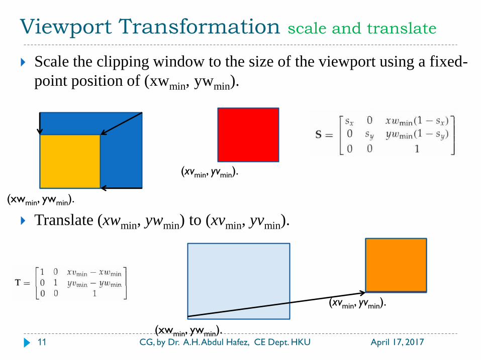
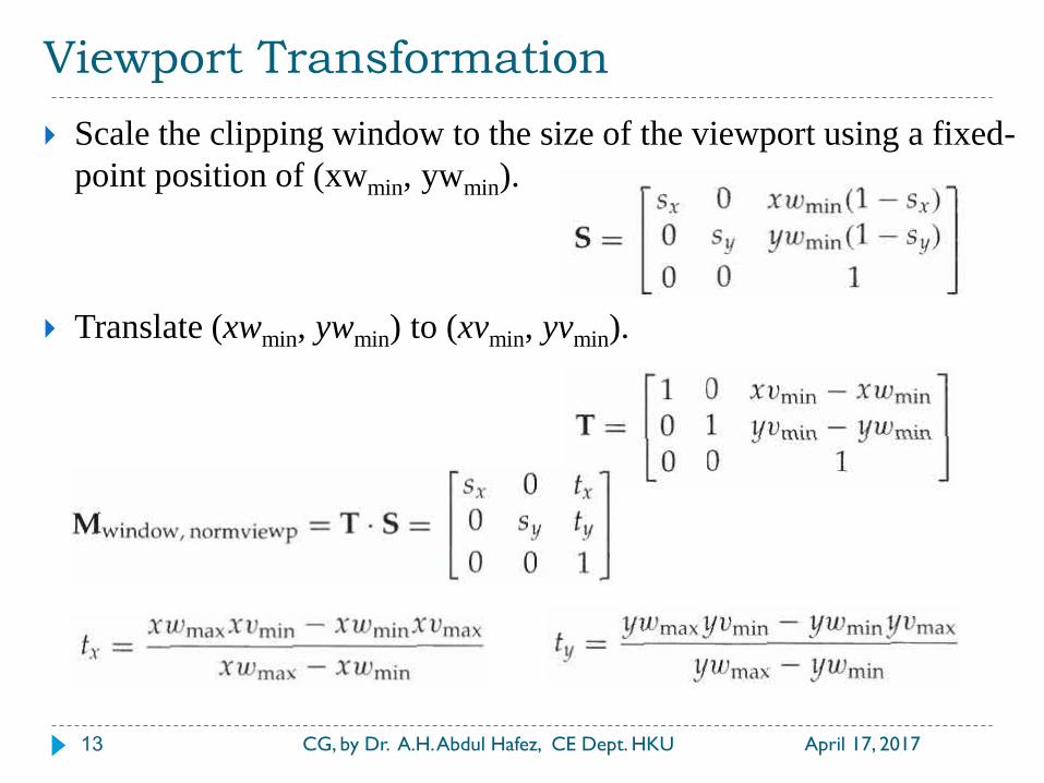
Scale the clipping window to the size of the viewport using a fixed-
point position of (xwmin, ywmin).
Translate (xwmin, ywmin) to (xvmin, yvmin).
(xwmin, ywmin).
(xvmin, yvmin).
(xwmin, ywmin).
(xvmin, yvmin).
Viewport Transformation
April 17, 2017 CG, by Dr. A.H. Abdul Hafez, CE Dept. HKU 12
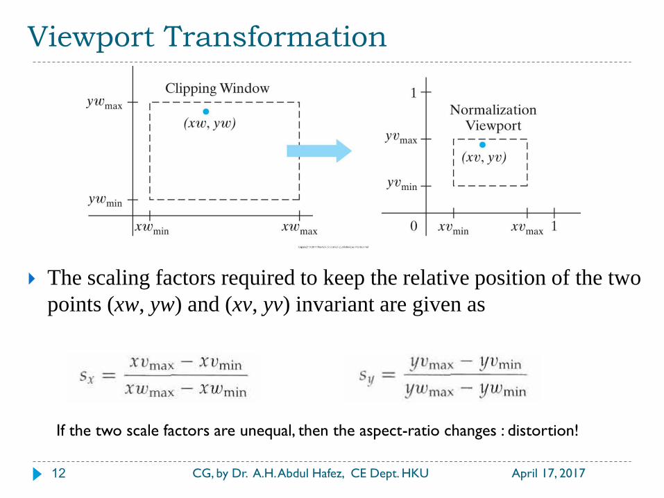
The scaling factors required to keep the relative position of the two
points (xw, yw) and (xv, yv) invariant are given as
If the two scale factors are unequal, then the aspect-ratio changes : distortion!
Viewport Transformation
April 17, 2017 CG, by Dr. A.H. Abdul Hafez, CE Dept. HKU 13
Scale the clipping window to the size of the viewport using a fixed-
point position of (xwmin, ywmin).
Translate (xwmin, ywmin) to (xvmin, yvmin).

Viewport Transformation
April 17, 2017 CG, by Dr. A.H. Abdul Hafez, CE Dept. HKU 14
Clipping window
to Normalized
square
Normalized
square to screen
viewport
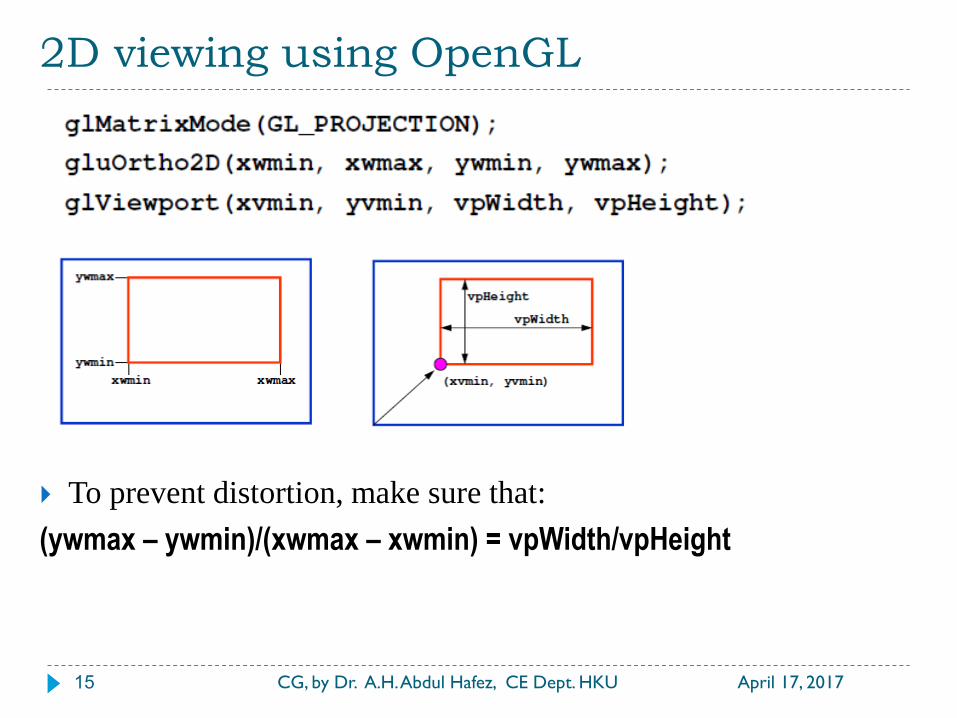
2D viewing using OpenGL
April 17, 2017 CG, by Dr. A.H. Abdul Hafez, CE Dept. HKU 15
To prevent distortion, make sure that:
(ywmax – ywmin)/(xwmax – xwmin) = vpWidth/vpHeight
2D Clipping
April 17, 2017 CG, by Dr. A.H. Abdul Hafez, CE Dept. HKU 16
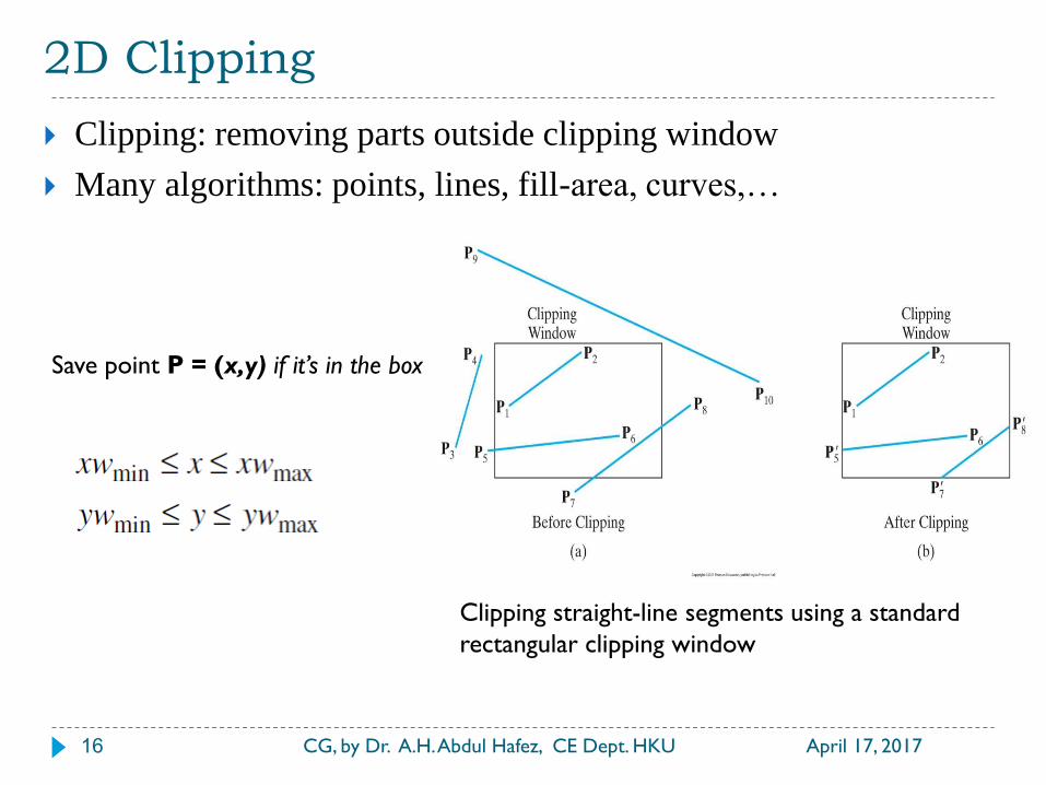
Clipping: removing parts outside clipping window
Many algorithms: points, lines, fill-area, curves,…
Save point P = (x,y) if it’s in the box
Clipping straight-line segments using a standard
rectangular clipping window
2D Clipping
April 17, 2017 CG, by Dr. A.H. Abdul Hafez, CE Dept. HKU 17
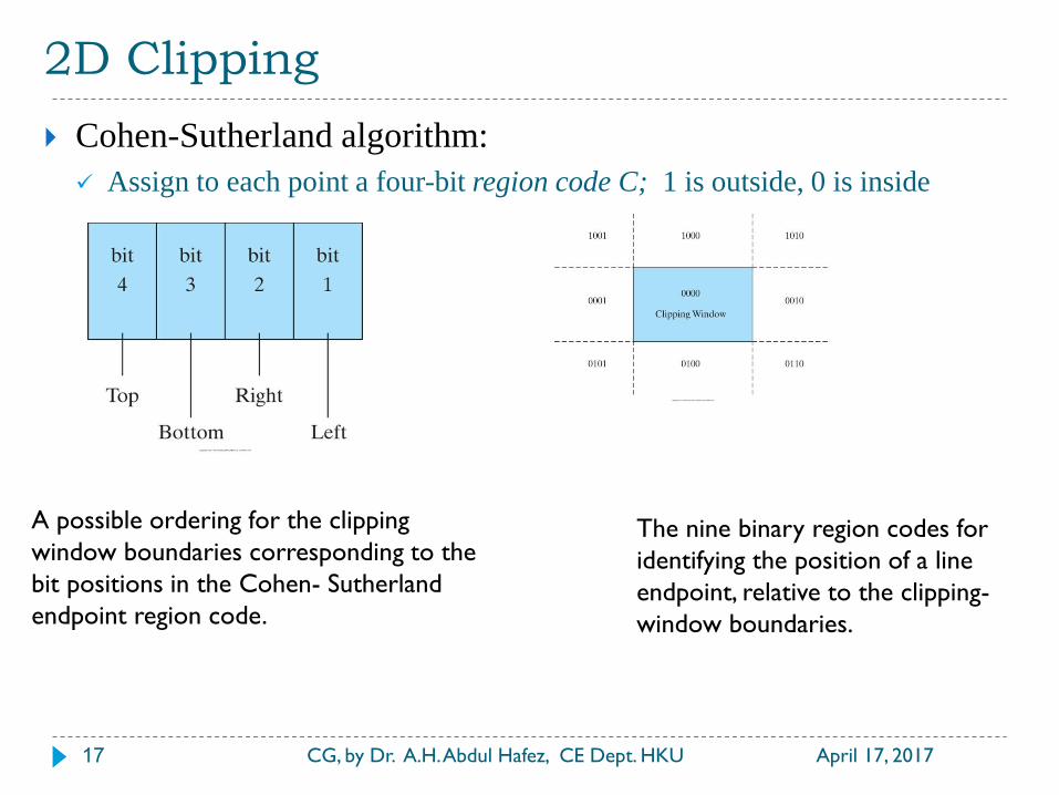
Cohen-Sutherland algorithm:
Assign to each point a four-bit region code C; 1 is outside, 0 is inside
A possible ordering for the clipping
window boundaries corresponding to the
bit positions in the Cohen- Sutherland
endpoint region code.
The nine binary region codes for
identifying the position of a line
endpoint, relative to the clipping-
window boundaries.
2D Clipping
April 17, 2017 CG, by Dr. A.H. Abdul Hafez, CE Dept. HKU 18
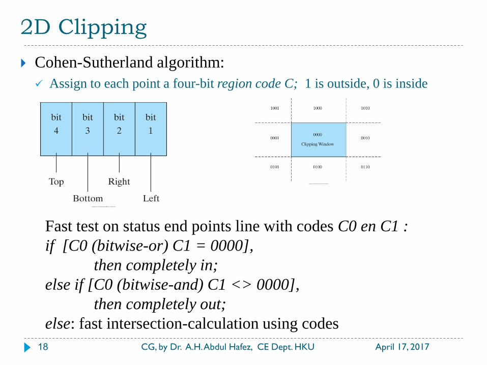
Cohen-Sutherland algorithm:
Assign to each point a four-bit region code C; 1 is outside, 0 is inside
Fast test on status end points line with codes C0 en C1 :
if [C0 (bitwise-or) C1 = 0000],
then completely in;
else if [C0 (bitwise-and) C1 <> 0000],
then completely out;
else: fast intersection-calculation using codes
The end of the Lecture
April 17, 2017 CG, by Dr. A.H. Abdul Hafez, CE Dept. HKU 19
Thanks for your time
Questions are welcome