computational endoscopy – a framework for improving
TRANSCRIPT
Computational endoscopy – a framework for improving spatial resolution in fiber bundle imaging JOHN P. DUMAS1, MUHAMMAD A. LODHI2, BATOUL A. TAKI2, WAHEED U. BAJWA2, MARK C. PIERCE1,* 1Rutgers, The State Univ. of New Jersey, Dept. of Biomedical Engineering, 599 Taylor Road, Piscataway, NJ, USA 08854 2Rutgers, The State Univ. of New Jersey, Dept. of Electrical and Computer Engineering, 94 Brett Road, Piscataway, NJ, USA 08854 * Corresponding author: [email protected]
Received XX Month XXXX; revised XX Month, XXXX; accepted XX Month XXXX; posted XX Month XXXX (Doc. ID XXXXX); published XX Month XXXX
This letter presents a framework for computational imaging (CI) in fiber-bundle-based endoscopy systems. Multiple observations are acquired of objects spatially modulated with different random binary masks. Sparse-recovery algorithms then reconstruct images with more resolved pixels than individual fibers in the bundle. Object details lying within the diameter of single fibers are resolved, allowing images with 41,663 resolvable points to be generated through a bundle with 2,420 fibers. Computational fiber bundle imaging of micro- and macro-scale objects is demonstrated using fluorescent standards and biological tissues, including in vivo imaging of a human fingertip. In each case, CI recovers detail that conventional endoscopy does not provide.
http://dx.doi.org/10.1364/OL.99.099999
Endoscopic imaging provides real-time visualization of tissue at sites within the body. Larger instruments such as colonoscopes and gastroscopes (5-10 mm diameter) use digital CCD or CMOS sensors located at the distal tip. Smaller devices (below around 3 mm diameter) including bronchoscopes and pediatric scopes use coherent fiber optic bundles to transmit images to an eyepiece or sensor at the proximal end. Fiber bundles are also used for confocal, multi-photon, and epi-fluorescence endomicroscopy. Configurations that use a single optical fiber typically require a mechanism for distal beam scanning. Fiber bundles avoid this challenge, but the number of resolvable points is limited to the number of fibers within the bundle. Post-processing techniques including Fourier filtering, spatial averaging, or interpolation can be applied to images acquired through a fiber bundle [1]. These methods can improve the visual appearance of images by removing the fiber bundle mask pattern, but the information content is still limited by the fiber packing density. Other techniques include image-compounding, combining multiple images as the distal end of the fiber bundle is laterally displaced between frames [2]. Bedard et al. use a similar concept,
but avoid the need to physically move the bundle by using a prism at the distal tip to spectrally encode spatially offset images that are captured in a snapshot multispectral image [3]. Image registration protocols have been developed to reconstruct a high-resolution image from a sequence of shifted, low-resolution frames for both known [4] and unknown [5, 6] displacements. Ravi et al. showed that deep learning algorithms further improve this approach [7]. Recently, Vyas et al. reported bundle-shifting confocal endomicroscopy with a nearly two-fold resolution improvement [8]. All the approaches discussed above improve the appearance of images acquired through fiber optic bundles, but each is based on individual fibers resolving only a single pixel of information. Alternative approaches aiming to resolve multiple points include wavefront shaping for imaging through a single multimode fiber [9]. Ohayon et al. implemented wavefront shaping endoscopy for deep brain imaging, but fiber bending remains a challenge of this technique [10]. However, a recent exploration of step-index and graded-index multimode fibers suggests a path forward [9], while Shin et al. demonstrated a compressed sensing approach for confocal endomicroscopy that is insensitive to bending of the fiber bundle [11]. Unfortunately, the bundle is used only to deliver structured light to the sample, instead of collecting emitted light, making clinical implementation difficult at present. This letter proposes a framework for resolution improvement using computational imaging (CI). Our approach requires collecting multiple images, or “observations”, of an object through different coded masks. We then use sparse-recovery algorithms to reconstruct an image that resolves multiple pixels within the diameter of each fiber in the bundle, producing images with a resolution determined by the density of elements in the mask rather than the number of fibers in the bundle. We use a CI framework based on coded masks located at a conjugate image plane, which we previously evaluated when imaging without a fiber bundle [12]. We extended the mathematical forward model from this earlier framework to account for imaging through a fiber bundle. Since the inter-fiber gaps are opaque, information about regions of the object located behind these gaps is lost and the algorithms can only recover
debindeTofothreplatha s whmsydoforeknve whthfrodisythTomwensua menob(Sfluembeelesizpr
Figob
etails within thenary {0, 1} matesignate where so construct this r pixels found the inter-fiber regeconstructed imaced at a conjuhrough k differensingle n × n pixel ⨀here ∗ denotesmultiplication, h iystem non-idealiownsampling. Ermat of epresentation of nown system ectorized n2 × 1 o here is an he diagonal, om h, D combinagonal matrix wystem-dependenhrough our imago realize themeasurement mae shift the meanntries, and we shubtracting from mask with all enThe benchtop ndoscopy approbjects. A 470 Semrock FF01-4uorescence is immbedded in a TIetween sets of raements with 2 ×ze of 350 × 35rojected onto on
g. 1. System dbjects are displaye
e intra-fiber regtrix, B, is includspatial informatmatrix, circle deto lie within fibegions. We choomage, X, to matcugate image plant random binarl camera observ⨀ ∗ ⨀s linear convos a Gaussian conities [12], and DrEquation (1) canoise forf the m2 × 1 objedependent mobservations, yk
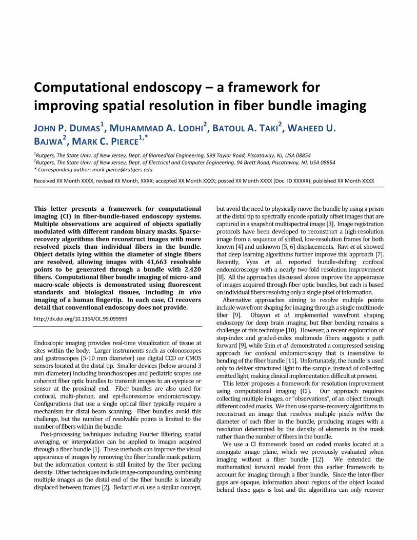
m2 × m2 diagonais a block Toepnes downsampliwith the entriesnt measuremenging setup can bee zero-mean atrices used in trn value of our mhift the values ieach an image ontries set to 0.5 [platform constroach (Fig. 1) is nm LED with 452/45-25) illumaged onto a dI LightCrafter 65andom binary m× 2 binning of D0. The modulane end of a flexibl
diagram for comed directly at the
gions where lighded within our tion about the saetection is used er boundaries, aose the dimensich those of an ane. The objecry masks. Our fvation Yk is defin⨀ noilution, ⨀ denonvolution kernelr and Dc indicatean be modified r sparse recoverect, x, is solved feasurement m: noisal matrix with mplitz convolutioning in both direcs of B on its diant matrix for ee expressed as distribution craditional sparsemasks by subtrain the associatedof a uniform obj13]. ructed to test thconfigured to ia 429-474 nmuminates the sigital micromirr500 module thamasks, each contMD mirrors for ated image of tle fiber optic bun
mputational endomask plane.
ht is collected. system model ample is acquireto set a value ofand 0 for pixels ions of our targm × m mask, Mct is then imagforward model fned as: ise (otes elementwil that accounts fe two-dimensionto fit the generry, where a vectfor using multipmatrices, Ak, ane (mask elements on matrix obtainctions, and isagonal. Thus, theach observatiocharacteristic e-recovery setupacting 0.5 from d observations bect taken throughis computationimage fluorescem bandpass filtsample. Sampror device (DMat rapidly switchtaining 700 × 70an effective mathe object is thndle (Schott
oscopy. Synthe
A to ed. f 1 in get Mk, ed for (1) ise for nal ral tor ple nd (2) on ed s a the on . of ps, all by gh nal ent ter ple D) hes 00 ask en
etic
Image Bfibers, eto achieof the bonto a the probandpacameraapproxFig. 2targetpatternbundle allowedpixel vaknown in Figs.fiber leof-viewdoes norecoverresolveregionsin Figs. overlaidrepreseshow cfeatureWe recoverchoice iimagesproxim[12], bunderlyefficienconstravariationegativvisually2(i) anprocess3.4 GHzTVNN areconstrecoverconvenhighlighbe resopairs arthe CI rsize of tmappeapproxprofilesmaximaare resresolveconven
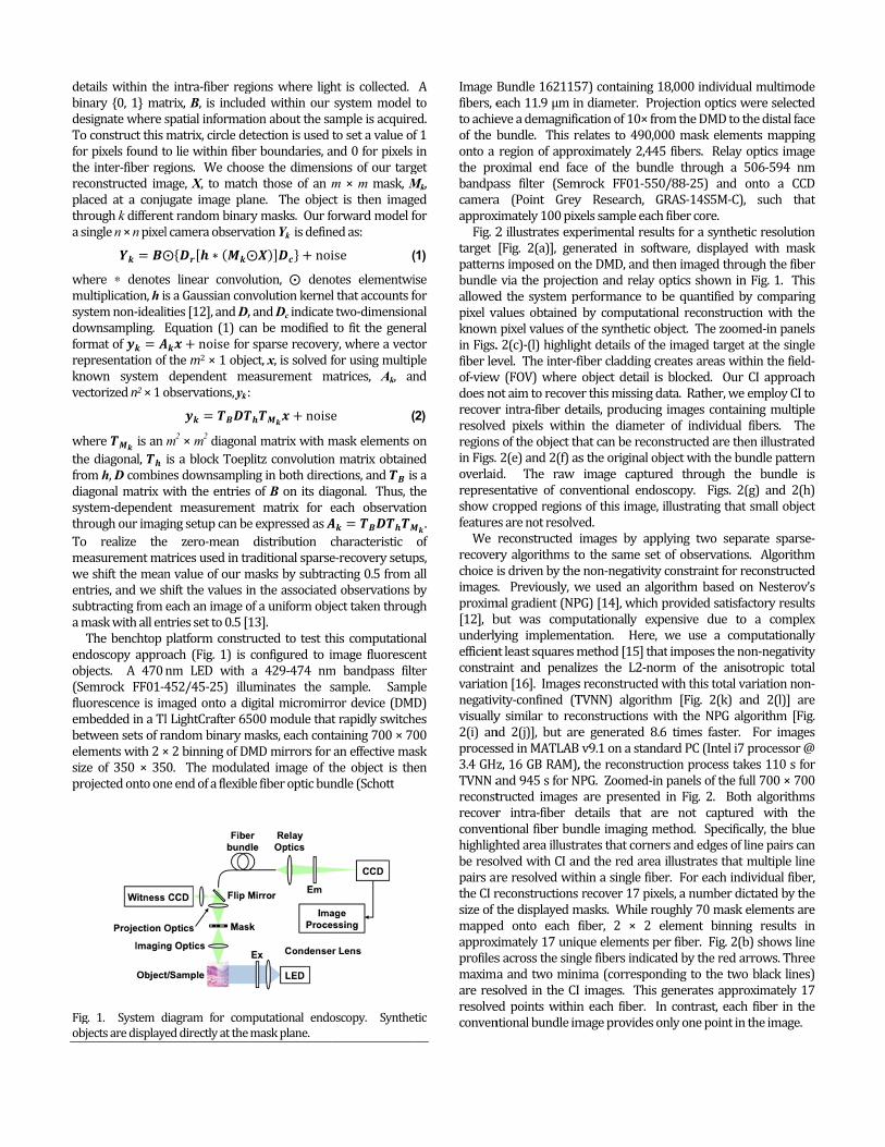
Bundle 162115each 11.9 μm ineve a demagnificbundle. This reregion of approoximal end facass filter (Sema (Point Greyximately 100 pix2 illustrates exp[Fig. 2(a)], genns imposed on the via the projectd the system pevalues obtained n pixel values of . 2(c)-(l) highligevel. The inter-fw (FOV) where ot aim to recover intra-fiber deted pixels withins of the object th2(e) and 2(f) asd. The raw entative of convcropped regionses are not resolvereconstructed iry algorithms tois driven by thes. Previously, wmal gradient (NPbut was compuying implemennt least squares maint and penalion [16]. Imagesvity-confined (Ty similar to recnd 2(j)], but aresed in MATLAB z, 16 GB RAM), and 945 s for Ntructed images r intra-fiber dntional fiber bunhted area illustrolved with CI anre resolved withreconstructions the displayed md onto each fximately 17 uniqs across the singa and two minisolved in the CI ed points withinntional bundle im
57) containing 1n diameter. Procation of 10× froelates to 490,00oximately 2,445ce of the bundmrock FF01-550y Research, Gxels sample eachperimental resulnerated in softwthe DMD, and thtion and relay oerformance to bby computatiothe synthetic obght details of thefiber cladding crobject detail iser this missing dtails, producing n the diameterhat can be recons the original obimage captureventional endos of this image, ed. images by appo the same set e non-negativity we used an algoPG) [14], which putationally expntation. Here, method [15] thaizes the L2-nors reconstructed wTVNN) algorithmconstructions we generated 8.6v9.1 on a stand, the reconstrucNPG. Zoomed-inare presented details that arndle imaging mrates that cornernd the red area hin a single fiberecover 17 pixemasks. While rofiber, 2 × 2 eque elements pegle fibers indicatima (correspon images. This gn each fiber. Inmage provides o
18,000 individuaojection optics wom the DMD to t00 mask eleme5 fibers. Relay dle through a 50/88-25) and GRAS-14S5M-C),h fiber core. lts for a synthetware, displayedhen imaged throoptics shown inbe quantified bnal reconstructbject. The zoome imaged targetreates areas wits blocked. Our data. Rather, we images containr of individual nstructed are thebject with the bued through thscopy. Figs. 2(illustrating thatplying two sepaof observationsconstraint for rorithm based oprovided satisfapensive due towe use a comat imposes the norm of the aniswith this total vm [Fig. 2(k) awith the NPG alg6 times faster. dard PC (Intel i7 ction process takn panels of the fuin Fig. 2. Bothre not capturemethod. Specificrs and edges of lillustrates that er. For each indels, a number diughly 70 mask element binniner fiber. Fig. 2(bted by the red anding to the twogenerates appron contrast, eachonly one point in
al multimode were selected the distal face ents mapping optics image 506-594 nm onto a CCD , such that tic resolution d with mask ough the fiber n Fig. 1. This by comparing tion with the med-in panels t at the single thin the field-CI approach employ CI to ning multiple fibers. The en illustrated undle pattern e bundle is (g) and 2(h) t small object arate sparse-s. Algorithm reconstructed on Nesterov’s actory results o a complex mputationally on-negativity sotropic total variation non-and 2(l)] are gorithm [Fig. For images processor @ kes 110 s for ull 700 × 700 th algorithms ed with the ally, the blue line pairs can multiple line dividual fiber, ictated by the elements are ng results in b) shows line arrows. Three o black lines) oximately 17 h fiber in the n the image.
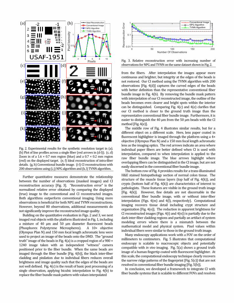
Fig. 2. Experimental results for the synthetic resolution target in (a). (b) Plot of line profiles across a single fiber (red arrows in (d-l)). (c, d) Zoom in of a 1.6 × 0.7 mm region (blue) and a 0.7 × 0.2 mm region (red) on the displayed target. (e, f) Ideal reconstruction of intra-fiber details. (g, h) Conventional bundle image. (i-l) CI reconstructions with 200 observations using (i, j) NPG algorithm and (k, l) TVNN algorithm. Further quantitative measures demonstrate the relationship between the number of observations (masked images) and CI reconstruction accuracy [Fig. 3]. “Reconstruction error” is the normalized relative error obtained by comparing the displayed (true) image to the conventional and CI reconstructed images. Both algorithms outperform conventional imaging. Using more observations is beneficial for both NPG and TVNN reconstructions. However, beyond 80 observations, additional measurements do not significantly improve the reconstructed image quality. Building on the quantitative evaluation in Figs. 2 and 3, we next imaged real objects with the platform illustrated in Fig. 1, including a mixture of 40 μm and 50 μm diameter fluorescent beads (Phosphorex Polystyrene Microspheres). A 10× objective (Olympus Plan N) and 150 mm focal length achromatic lens were used to project an image of the beads onto the DMD. The “ground truth” image of the beads in Fig. 4(a) is a cropped region of a 980 × 1240 image taken with an independent “witness” camera positioned prior to the fiber bundle. When the same beads are imaged through the fiber bundle [Fig. 4(b)], the black inter-fiber cladding and pixilation due to individual fibers reduces overall brightness and image quality such that the edges of the beads are not well defined. Fig. 4(c) is the result of basic post processing of a single observation, applying bicubic interpolation to Fig. 4(b) to replace the fiber bundle mask pattern with values interpolated
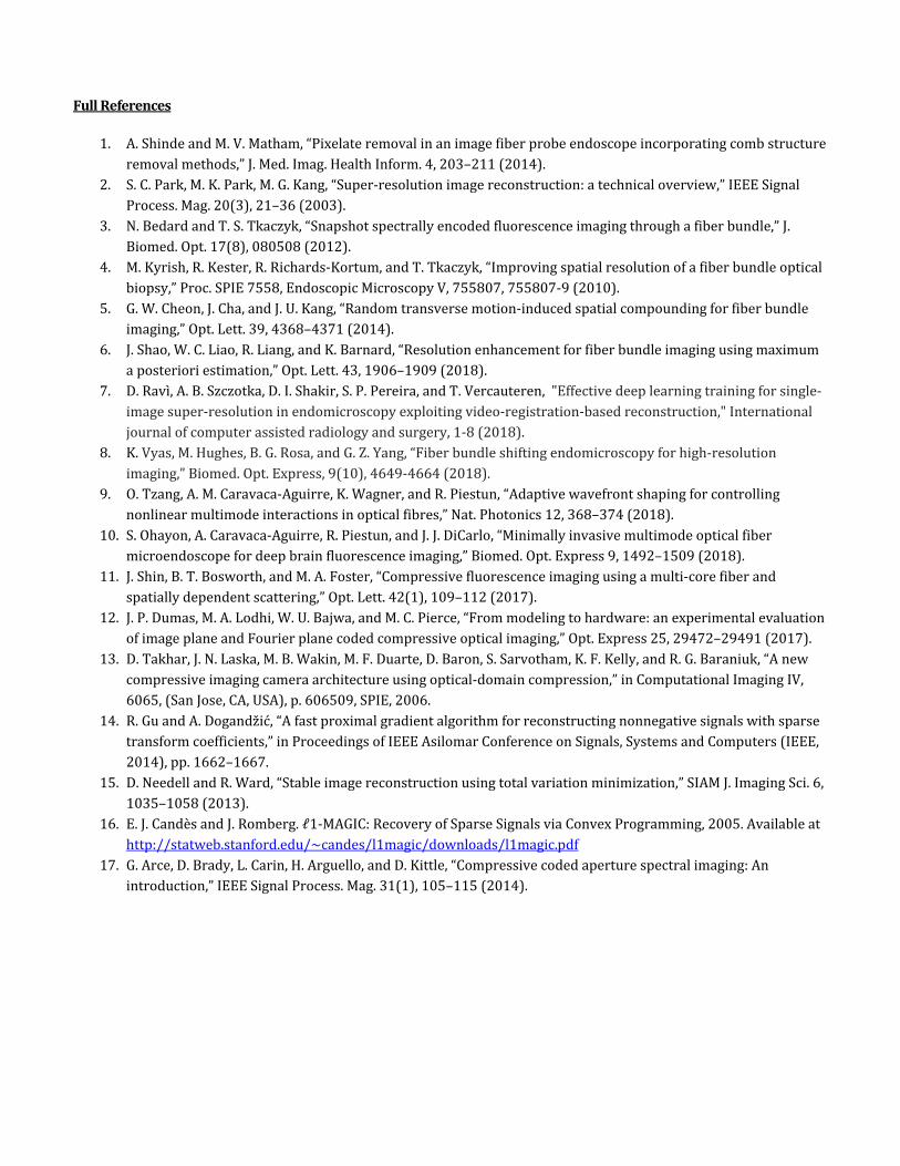
Fig. 3. Relative reconstruction error with increasing number of observations for NPG and TVNN on the same dataset shown in Fig. 2. from the fibers. After interpolation the images appear more continuous and brighter, but integrity at the edges of the beads is not restored. Our CI method using the TVNN algorithm with 200 observations [Fig. 4(d)] captures the curved edges of the beads with better definition than the representative conventional fiber bundle image in Fig. 4(b). By removing the bundle mask pattern with interpolation of our CI reconstructed image, the outline of the beads becomes even clearer and bright spots within the interior can be distinguished. Comparing Fig. 4(c) and 4(e) clarifies that our CI method is closer to the ground truth image than the representative conventional fiber bundle image. Furthermore, it is easier to distinguish the 40 μm from the 50 μm beads with the CI method [Fig. 4(e)]. The middle row of Fig. 4 illustrates similar results, but for a different object on a different scale. Here, lens paper coated in fluorescent highlighter is imaged through the platform using a 4× objective (Olympus Plan N) and a 150 mm focal length achromatic lens as the imaging optics. The red arrows indicate an area where individual paper fibers are better defined when CI is used with interpolation, compared to when interpolation is applied to the raw fiber bundle image. The blue arrows highlight where overlapping fibers can be distinguished in the CI image, but are not easily discerned in the conventional fiber bundle image. The bottom row of Fig. 4 provides results for a trans-illuminated H&E stained histopathology section of normal colon tissue. The structure of the muscle tissue layers (top half of Fig. 4(k)), and crypts (bottom half of Fig. 4(k)) are characteristics of interest to pathologists. These features are visible in the ground truth image [Fig. 4(k)]. However, fine details are not discernable in the conventional fiber bundle image, with or without inter-fiber interpolation (Figs. 4(m) and 4(l), respectively). Computational imaging recovers tissue detail including crypt structure and organization [Fig. 4(o)]. The reduction in apparent brightness for CI reconstructed images (Figs. 4(i) and 4(n)) is partially due to the dark inter-fiber cladding regions and partially an artifact of system modeling errors where there is a mismatch between the mathematical model and physical system. Pixel values within individual fibers were similar to those in the ground truth image. Many endoscopy applications work with a FOV on the order of millimeters to centimeters. Fig. 5 illustrates that computational endoscopy is scalable to macroscopic objects and potentially compatible with in vivo imaging. Fig. 5(a) shows a ground truth image of a human fingertip coated with fluorescent highlighter. At this scale, the computational endoscopy technique clearly recovers the narrow ridge patterns of the fingerprint [Fig. 5(c)] that are not resolved in conventional fiber bundle imaging [Fig. 5(b)]. In conclusion, we developed a framework to integrate CI with fiber bundle systems that is scalable to different FOVs and resolves
(a)
(c) (e) (g) (i)
(k)
(d) (f)
(h) (j) (l)
(b)
Pixels Pixel In
tensity
Number Of Observations0 50 100 150 200
Rec
on
stru
ctio
n E
rro
r
0.01
0.1
1 Conventional ImageNPG AlgorithmTVNN Algorithm

17nofibalgenrenualgwoobimoppabupaFigwhraofco
Figimint
FigBi7 pixels within thot attempt to recber cladding, butgorithms for rndoscopes. Howeconstruction timumber of obsergorithms to solvould mean recobservations. Smpractical in theption for miniaatterned with a cundle tip with a attern for CI in og. 2(a) producedhen using 100 andom masks uf0.0336). Furthombined with sp
g. 5. Fluorescent hmage. (b) Singterpolation. (c) C
g. 4. (a, f, k) Groucubic interpolatiohe diameter of acover detail fromt represents a stresolution imprwever, two keyme must be redrvations. At prve ill-conditionedovering 17 poinecond, using ae confined spacaturization wouchrome-etched mminiature actuour platform whd an image withobservations, using the same hermore, if the Cpectral multiplex
highlighter appliegle image captCI reconstruction
und truth imageson on images (b, ga single fiber. Thm object regionstep toward usinrovement in fiy challenges remduced, potentiallresent, we do nd CI problems. Ints per fiber wia DMD for maces inherent to uld use a smamask that is rotaator. Using sucen imaging the sh a reconstructiosimilar to resunumber of obCI principles prxing, it may be po
ed to the fingertiptured through with interpolatio
s. (b, g, l) Single ig, l). (d, i, n) CI rehis approach dos within the integ sparse-recoveiber-bundle-basmain. First, imay by reducing thnot use optimizIn our context thith fewer than 1ask generationendoscopy. Oall glass windoated in front of thh a rotating masynthetic target on error of 0.034ults presented fbservations (errresented here aossible to
p. (a) Ground truthe bundle wion.
images captured econstruction withoes er-ery ed age the ed his 17 is ne ow the ask t in 44 for ror are
uth ith
reconsteliminaintroduadvancFundinECCS-1Refere1. A. Shin2. S. Par3. N. Bed4. M. Ky
07 (25. G. W. 6. J. Shao7. D. Rav
Com8. K. Vya
(20189. O. Tza
Phot10. S. Oh
Opt. 11. J. Sh12. J. P. D
294713. D. Ta
and R14. R. Gu
166215. D. Ne16. E. Ca
http:17. G. Ar
Mag.
through the bunh 200 observatiotruct a high-resating the needuction of CI conce progress towang. National S1509260). ences nde and M. V. Matk, M. Park, and M.dard and T. S. Tkac
yrish, R. Kester, R. R2010).
Cheon, J. Cha, ando, W. Liao, R. Liangvi, A. B. Szczotka, Dput. Assist. Radiol.
as, M. Hughes, B. G8). ang, A. M. Caravacatonics 12, 368 (201hayon, A. M. CaravExpress 9, 1492 (2in, B. T. Bosworth, Dumas, M. A. Lodh
72 (2017). akhar, J. Laska, M. R. Baraniuk, In SPIEu, and A. Dogandzi2 (2014). eedell, and R. War
andes and J. Romb://statweb.stanfordrce, D. Brady, L. Ca. 31, 105 (2014).
ndle, representinons. (e, j, o) CI imasolution image d for moving ncepts to endoard in vivo opticaScience Foundatham, J. Med. Imag Kang, in IEEE Signa
czyk, J. Biomed. OpRichards-Kortum, a
d J. U. Kang, Opt. Leg, and K. Barnard, OD. I. Shakir. S. P. Per Surg. 13, 917 (201
G. Rosa, and G Yang
a-Aguirre, K. Wagn18). vaca-Aguirre, R. Pie2018).
and M. A. Foster, hi, W. U. Bajwa, an
Wakin, M. Duarte,E Computational Imic in Proc. Asilomar
rd, SIAM J. Imag. Scberg, 2005 [Online]d.edu/~candes/l1m
arin, H. Arguello, an
ng conventional fiages (d, i, n) with in a single snparts. We oscopy has the al biopsy. ation (NSF) (Cg. Heal. Inform. 4, al Process. Mag. 20
pt. 17, 080508 (201and T. Tkaczyk, Pro
ett. 39, 4368 (2014Opt. Lett. 43, 1906 reira, and T. Vercau18). g, Biomed. Opt. Ex
ner, and R. Piestun
estun, and J. J. DiCa
Opt. Lett. 42, 109 (nd M. C. Pierce, Op
, D. Baron, S. Sarvomaging IV 6065, 60r Conf. Signals, Sys
ci. 6, 1035 (2013).. Available: magic/downloads/nd D. Kittle, IEEE Sig
fiber-bundle imagbicubic interpolanapshot [17], believe the potential to CCF-1453073,
203 (2014). 0, 21 (2003). 12). oc. SPIE 7558,
4). (2018).
uteren, Int. J.
xpress 9, 4649
. Nat.
arlo, Biomed.
(2017). pt. Express 25,
otham, K. Kelly, 06509 (2006). st. Comput.
/l1magic.pdf gnal Process.
ging. (c, h, m)ation.
Full References 1. A. Shinde and M. V. Matham, “Pixelate removal in an image fiber probe endoscope incorporating comb structure removal methods,” J. Med. Imag. Health Inform. 4, 203–211 (2014). 2. S. C. Park, M. K. Park, M. G. Kang, “Super-resolution image reconstruction: a technical overview,” IEEE Signal Process. Mag. 20(3), 21–36 (2003). 3. N. Bedard and T. S. Tkaczyk, “Snapshot spectrally encoded fluorescence imaging through a fiber bundle,” J. Biomed. Opt. 17(8), 080508 (2012). 4. M. Kyrish, R. Kester, R. Richards-Kortum, and T. Tkaczyk, “Improving spatial resolution of a fiber bundle optical biopsy,” Proc. SPIE 7558, Endoscopic Microscopy V, 755807, 755807-9 (2010). 5. G. W. Cheon, J. Cha, and J. U. Kang, “Random transverse motion-induced spatial compounding for fiber bundle imaging,” Opt. Lett. 39, 4368–4371 (2014). 6. J. Shao, W. C. Liao, R. Liang, and K. Barnard, “Resolution enhancement for fiber bundle imaging using maximum a posteriori estimation,” Opt. Lett. 43, 1906–1909 (2018). 7. D. Ravì, A. B. Szczotka, D. I. Shakir, S. P. Pereira, and T. Vercauteren, "Effective deep learning training for single-image super-resolution in endomicroscopy exploiting video-registration-based reconstruction," International journal of computer assisted radiology and surgery, 1-8 (2018). 8. K. Vyas, M. Hughes, B. G. Rosa, and G. Z. Yang, “Fiber bundle shifting endomicroscopy for high-resolution imaging,” Biomed. Opt. Express, 9(10), 4649-4664 (2018). 9. O. Tzang, A. M. Caravaca-Aguirre, K. Wagner, and R. Piestun, “Adaptive wavefront shaping for controlling nonlinear multimode interactions in optical fibres,” Nat. Photonics 12, 368–374 (2018). 10. S. Ohayon, A. Caravaca-Aguirre, R. Piestun, and J. J. DiCarlo, “Minimally invasive multimode optical fiber microendoscope for deep brain fluorescence imaging,” Biomed. Opt. Express 9, 1492–1509 (2018). 11. J. Shin, B. T. Bosworth, and M. A. Foster, “Compressive fluorescence imaging using a multi-core fiber and spatially dependent scattering,” Opt. Lett. 42(1), 109–112 (2017). 12. J. P. Dumas, M. A. Lodhi, W. U. Bajwa, and M. C. Pierce, “From modeling to hardware: an experimental evaluation of image plane and Fourier plane coded compressive optical imaging,” Opt. Express 25, 29472–29491 (2017). 13. D. Takhar, J. N. Laska, M. B. Wakin, M. F. Duarte, D. Baron, S. Sarvotham, K. F. Kelly, and R. G. Baraniuk, “A new compressive imaging camera architecture using optical-domain compression,” in Computational Imaging IV, 6065, (San Jose, CA, USA), p. 606509, SPIE, 2006. 14. R. Gu and A. Dogandžić, “A fast proximal gradient algorithm for reconstructing nonnegative signals with sparse transform coefficients,” in Proceedings of IEEE Asilomar Conference on Signals, Systems and Computers (IEEE, 2014), pp. 1662–1667. 15. D. Needell and R. Ward, “Stable image reconstruction using total variation minimization,” SIAM J. Imaging Sci. 6, 1035–1058 (2013). 16. E. J. Candès and J. Romberg. ℓ1-MAGIC: Recovery of Sparse Signals via Convex Programming, 2005. Available at http://statweb.stanford.edu/~candes/l1magic/downloads/l1magic.pdf 17. G. Arce, D. Brady, L. Carin, H. Arguello, and D. Kittle, “Compressive coded aperture spectral imaging: An introduction,” IEEE Signal Process. Mag. 31(1), 105–115 (2014).