comprehensive study of plasma-wall sheath transport phenomena · comprehensive study of plasma-wall...
TRANSCRIPT

1
Comprehensive Study of Plasma-Wall Sheath Transport Phenomena 2012 Space Propulsion and Power Program Review
September 10, 2012, Arlington, VA Dr. Mitchell L. R. Walker, Georgia Institute of Technology, Associate Professor, Principal Investigator, Aerospace Engineering, Atlanta, GA 30332 Dr. Michael Keidar , George Washington University, Associate Professor, Micropropulsion and Nanotechnology Laboratory, Washington, DC 20052 Dr. William Jud Ready, Georgia Tech Research Institute, Principal Research Engineer & Adjunct Professor, Electro-Optical Systems Lab, Atlanta, GA 30332Dr. Julian J. Rimoli, Georgia Institute of Technology, Assistant Professor, Aerospace Engineering, Atlanta, GA 30332 Dr. Greg Thompson, University of Alabama, Associate Professor, Metallurgical and Materials Engineering, Tuscaloosa, AL 35487 The research effort aims to determine the fundamental transport properties (mass, charge, and energy) within the plasma sheath, and determine the relationship between plasma properties and wall surface modification as a function of wall material. Investigators from the Georgia Institute of Technology (GT), University of Alabama (UA), and George Washington University (GWU) have begun a comprehensive, integrated, multidisciplinary study on the nature and transport properties of the interaction between plasma and a confining wall material. The hypothesis of this research effort is that standard plasma assumptions break down in the plasma sheath and are greatly affected by the microstructural properties of the wall. The approach uses measurements, theoretical analysis, and modeling of the plasma properties inside the plasma sheath, as well as measurements and modeling of the material response to the plasma to understand the plasma-wall interaction.
Collaborative Research Approach The research is organized into two major research areas: (1) interrogation and theoretical modeling of the plasma up to the wall boundary, and (2) interrogation and modeling of the wall up to the plasma boundary. During Year 1, UA used Microscopy (SEM), Atomic Force Microscope (AFM), and Transmission Electron Microscopy (TEM) to characterize virgin and exposed insulator material. The surface mechanical properties were measured using Nano-Indentation (NI). UA has developed the capability to characterize the microstructure and phase of boron nitride (BN) wall material samples, and has performed analyses using X-Ray Diffraction (XRD), In addition, UA work with GT to identify unique erosion mechanisms to assist with material model development. GTRI worked with GT to calibrate the ion-assisted deposition plasma source (IAD) for use as a controlled plasma exposure environment for BN samples. GTRI has exposed and characterized BN samples to aid to guide material model development. GWU has developed a plasma simulation methodology that accounts for the multiple length scales. GWU has performed and published simulations studying the interaction of the near-wall plasma sheath with a magnetic field, and modeled the plasma sheath of the GT thick-sheath (~10mm) plasma cell. Figure 1shows the collaborative research team functional relationship between models and experimental data for both the plasma and wall sides of the investigation.

Report Documentation Page Form ApprovedOMB No. 0704-0188
Public reporting burden for the collection of information is estimated to average 1 hour per response, including the time for reviewing instructions, searching existing data sources, gathering andmaintaining the data needed, and completing and reviewing the collection of information. Send comments regarding this burden estimate or any other aspect of this collection of information,including suggestions for reducing this burden, to Washington Headquarters Services, Directorate for Information Operations and Reports, 1215 Jefferson Davis Highway, Suite 1204, ArlingtonVA 22202-4302. Respondents should be aware that notwithstanding any other provision of law, no person shall be subject to a penalty for failing to comply with a collection of information if itdoes not display a currently valid OMB control number.
1. REPORT DATE 10 SEP 2012 2. REPORT TYPE
3. DATES COVERED 00-00-2012 to 00-00-2012
4. TITLE AND SUBTITLE Comprehensive Study of Plasma-Wall Sheath Transport Phenomena
5a. CONTRACT NUMBER
5b. GRANT NUMBER
5c. PROGRAM ELEMENT NUMBER
6. AUTHOR(S) 5d. PROJECT NUMBER
5e. TASK NUMBER
5f. WORK UNIT NUMBER
7. PERFORMING ORGANIZATION NAME(S) AND ADDRESS(ES) Georgia Institute of Technology,Guggenheim School of Aerospace Engineering,Atlanta,GA,30332
8. PERFORMING ORGANIZATIONREPORT NUMBER
9. SPONSORING/MONITORING AGENCY NAME(S) AND ADDRESS(ES) 10. SPONSOR/MONITOR’S ACRONYM(S)
11. SPONSOR/MONITOR’S REPORT NUMBER(S)
12. DISTRIBUTION/AVAILABILITY STATEMENT Approved for public release; distribution unlimited
13. SUPPLEMENTARY NOTES Presented at the 2012 AFOSR Space Propulsion and Power Program Review held 10-13 September inArlington, VA. U.S. Government or Federal Rights License
14. ABSTRACT
15. SUBJECT TERMS
16. SECURITY CLASSIFICATION OF: 17. LIMITATION OF ABSTRACT Same as
Report (SAR)
18. NUMBEROF PAGES
20
19a. NAME OFRESPONSIBLE PERSON
a. REPORT unclassified
b. ABSTRACT unclassified
c. THIS PAGE unclassified
Standard Form 298 (Rev. 8-98) Prescribed by ANSI Std Z39-18

2
Figure 1 – Collaborative Research Strategy
1 Materials Characterization (Thompson) During the course of year 1, a M26 grade Combat© 60 wt% boron nitride (BN) - 40 wt% silica (SiO2) hot-pressed composite, manufactured by Saint Gobain Ceramic Materials Company, was characterized. This material was machined as part of the chamber wall used in a GA Tech Hall Effect Thruster (HET), shown in figure 1. A subsection of this wall material was removed to investigate erosion patterns. The wall material was exposed to a Xe based plasma operated between 1.5-5 kW for over 2000 hours. Three distinct erosion regions were identified: low erosion (LE), mild erosion (ME), and high erosion (HE), Figure 2(b)-(c). The non-uniform erosion across the material is contributed to the variation in potential drop the chamber wall experiences. Between the anode exit plane and the ionization region, figure 2(a), the HE portion of the wall is exposed to neutral gas temperatures of approximately 850 and 1000K.Once the plasma ionizes and accelerates across this region, a sharp potential drop near the exit plane of the thruster occurs and the ions’, within the plasma, impact energies rise significantly from <10 eV to between 100 and 300 eV. Erosion in this acceleration region is distinct and is much greater in magnitude than upstream of this zone. This difference in impact energies contributes to the rate of sputter erosion between the microstructures.

3
Figure 2 – (a) Schematic of a HET and the regions of characterization (b) Optical micrograph of the eroded M26 composite (c) SEM micrographs of the three distinct eroded regions.
The distinction of these regions was determined by the discoloration, figure 2(b), and later by the erosion defects evident on the sample surface, figure 2(c). The HE area had the darkest discoloration, which has been contributed to free carbon deposited on the surface from the graphite electrode used in the thruster design. XRD confirmed hexagonal close packed (hcp) BN and amorphous silica phases present in each region. BN and silica are known to have polymorphs but evidence of multiple phases was not detected. The lack of polymorphs of either phase indicates that the base material is stable in the plasma environment. The LE region, figure 2(c), revealed a granular microstructure commonly observed in hot pressed powder mixtures. The ME region, figure 2(c), revealed a polish-like surface appearance with macro-cracking within the material. The HE region revealed three distinct surface features, as noted in figure 2(c). There were regions where it appeared that a particular phase of the material dislodged from the matrix leaving a smooth surface (denoted as #1 in Figure 3(a)). In other regions, the surface was modified into jagged, surface protrusions (denoted as #2 in Figure 3(a)). The jagged surface protrusions consisted of a laminated morphology of BN and silica indicative of the atomic contrast between the phases seen in the backscattered electron micrograph (solid arrow) in Figure 3(b). Finally, macro-cracking was evident as previously observed in the ME region (denoted as #3 in Figure 3(a)). The backscattered SEM micrograph revealed that the micro-cracks were predominantly in the BN phases (dashed arrows), Figure 3(b). TEM from a HE region confirmed that the micro-cracking was numerous and along the basal plane of the BN, Figure 3(c).

4
Figure 3 – (a) Secondary electron SEM micrograph revealing smooth silica surface (#1), jagged protrusions (#2) and micro-cracking (#3) (b) Backscattered SEM micrograph revealing protrusions are laminated silica and BN and the micro-cracks are within the BN phase. (c) STEM-High angle annular dark field micrograph showing prevalent micro-cracking along the basal plane of the BN phase.
The chemical signature from the surface was quantified by X-ray Photoelectron Spectroscopy (XPS) in a Kratos Axis 165. XPS revealed a relative compositional change between each of the elements in three eroded regions, plotted as a histogram in Figure 4. As the sample because more eroded, an increase in the relative amounts of silicon and oxygen species and a corresponding decrease in the boron and nitrogen signals were noted. In addition, the carbon signal increased between the LE and HE regions and corresponds to the dark discoloration previously noted in Figure 1Figure 2. The relative increase of silica and decreasing BN indicates that the latter material is eroding at a faster rate than the former. This is surprising considering that the binding energy of BN is larger than silica. This erosion rate chemical dependence is believed to be a result of a larger fraction of the BN detaching form the surface of the composite, as evident in the remaining smooth silica surface in Figure 3(a). The fragmentation of the BN from the matrix would indicate a weak interphase-interface bond. The evidence of the degradation of BN in the matrix is its prevalent cracking which would weaken the material's structural integrity. As shown in the preliminary work of the controlled ion erosion instrumentation at GTRI, the team will explore this detachment in a more systemic means in year 2. The prevalent microcracking appears to be a major contributor the failure mechanisms of this composite in a plasma based environment. This cracking could be contributed to ion implantation effects and/or thermal induced stresses. Using the Stopping Range in Matter (SRIM) Monte Carlo program, and estimated acceleration voltages of The xenon ions in the plasma into the chamber wall, the mean penetration depth of xenon in BN and silica is just a few nanometers. The implantation of the ions could generate a local strain within each of the phases. Since silica is amorphous, it would have more free volume as compared to the close packed structure of BN and may explain the lack of significant cracking within this phase. In contrast, BN would either become locally disordered by the impacted ion into the surface which would need to create more free volume with its accompanying strain. The relative weaker out-of-plane basal bonds of BN could fail and lead to the microcracks that run parallel to the basal plane. Since xenon's chemical signature from the surface was not detected, it is believed that ion implantation was likely not the major contributor to microcracking and detachment. As will be described in the micro-modeling work below, the large thermal gradients on the surface and contribute to
Figure 4 – Histogram of chemical signatures from the three identified regions. Note the drop of B-N from the low to high regions.

5
sufficient thermally driven expansion. BN has anisotropic thermal expansion coefficients between the a- and c-axis which could cause this phase to expand different amounts relative to its orientation and within the surrounding silica interior. The confinement of the BN fibers within the silica causes the fiber to buckle and micro-crack along the basal plane. The details of which are described below.
2 Micro-modeling (Rimoli) During year one, the erosion modeling effort has been focused on identifying main erosion mechanisms in BN compounds under the effect of plasma. Towards this end, GT and UA have held several teleconferences and full (on-site) work days to better coordinate characterization and modeling efforts. Based on the observed evidence, the effects of two main erosion mechanisms are modeled: influence of thermal loads on micro-cracking of BN phase, and differential sputtering effect.
2.1 Thermal load effects The response of BN compounds under thermal loads is modeled by direct numerical simulation of the microstructure obtained form micrographs provided by UA. Anisotropic thermal expansion coefficient and elastic properties are assigned to each boron nitride grain, assuming that the basal planes are aligned with the preferential (longest) grain direction, see micrograph in Figure 5. The silica phase is assumed to be isotropic. A uniform change of temperature of 500 K is applied to the specimen while allowing it to freely expand. Thermal stresses resulting from this loading are summarized in Figure 5. It is worth noting that several grains are found to experience tensile stresses on the order of hundreds of MPa in the direction perpendicular to the basal plane (e1 in Figure 5) while experiencing similar compressive stresses on the orthogonal direction (e2 in Figure 5). Clearly, this stress state could easily lead to the kind of micro-cracks reported in previous sections.
Figure 5 – Thermal stresses on BN compound

6
2.2 Preliminary erosion-based modeling Preliminary runs of the sputter-erosion based model are believed to successfully recover the erosion striations observed in the eroded samples. The model permits the investigation of the sputtering of a heterogeneous material, combining an erosion rate model for each material derived from Yalin’s experimental sputtering data on HBC BN and quartz with 3D ray tracing techniques that account for shadowing effects. Runs were conducted on a 200x200 surface grid, 10x10x10 µm domain.
Figure 6 – Sputter-based erosion model (b, c) recovery of observed erosion striations (a)
3 Boron Nitride, Controlled Plasma Exposure (GTRI) The role of the Georgia Tech Research Institute in the collaboration is to expose wall material samples to known plasma conditions and to study those samples, as well as provide samples to UA and GT Prof. Rimoli. Working towards this role, GTRI has adapted and characterized an Ion-Assisted Deposition (IAD) tool for use as a controlled plasma exposure environment for generating eroded wall material samples and provided initial samples to UA. In addition, GTRI has performed contact profilometry, EDX, and SEM measurements of samples and provided equipment and assistance to Professor Rimoli’s investigations into the molecular dynamics of the erosion process.
3.1 IAD Characterization Two electrostatic probes were used in initial characterization of the IAD plasma environment, a Langmuir probe and a Retarding Potential Analyzer (RPA). The Langmuir probe could be considered the seminal plasma diagnostic, and a large amount of literature exists on the interpretation of the I-V traces. The interpretation method based on the orbital motion limited theory is reputable and is used in these measurements. The plasma potential measurement obtained from the Langmuir probe was used in processing measurements taken with the RPA to characterize the energy distribution of the ions that BN samples will be exposed to. The RPA consists of a series of biased grids that collectively act as a high-pass filter that only allows ions with energy higher than the ion repulsion grid to pass through to the collector. Increasing the voltage on the ion retarding grid repels ions with equal or less energy and as a result the collected current drops. It is shown in operation in Figure 8. This characterization showed that the IAD plasma was capable of stable operation for long duration sample exposure, and that it was able to provide ion beam energies of 40-160 eV.
3.2 Sample Erosion and Exposure (GTRI ���� UA) Several pieces and samples of a HET outer discharge channel wall from GA Tech (the AFRL/UM P5 Hall effect thruster) were sectioned and provided to UA for process development with BN. Additionally preliminary samples eroded in the IAD tool were provided to UA. These samples were exposed for 8 hours while operating the IAD at 40A discharge current, 60 V and 120 V ion energy, and 10 sccm argon gas flow.
Figure 7 – Sample holder and M26 samples for exposure in IAD tool
Figure 8 – RPA in plasma in IAD tool

7
In order to generate samples for exposure in the IAD, grade M26 BN rods were acquired from Precision Ceramics USA. The rods were initially 200 mm in length and 50.8 mm in diameter. In order to analyze the sample with atom probe tomography at University of Alabama, samples were cut to 6.35 mm thickness cylinders. These cylinders were then cut into quarters. Samples were then lathed in order to remove severe roughness imparted from the cutting blade. Lathed samples were cleaned with a solvent rinse, followed by DI water rinse and gentle heating at 100 °C in vacuum furnace in order to prevent unwanted oxidation. The ends of each as-received BN rod which were not exposed to the cutting blade or the lathe were preserved in order to analyze chemical or physical differences which may have occurred as a result of cutting. This analysis was performed using EDX and SEM. Surface roughness of the cut BN samples was analyzed using a Dektek 150 contact profilometer.
Figure 9 – (A-D) Sample SEM images of received BN: x1.50k - x20.0k
Figure 10 – (A-D) Sample SEM images of Cut BN: x1.50k - x20.0k
EDX was performed using a NORAN Six 300 EDX detector to qualitatively characterize the BN in both as-received and cut condition, which revealed that the cut sample has not been negatively impacted and that the relative chemical composition of the sample remains intact and undisturbed by the cutting process, and that no impurities were imparted into the sample via cutting and cleaning. Additionally, Scanning Electron Microscopy (SEM) was performed using a Hitachi S-4700 scanning electron microscope to note any physical differences between the as-received and cut BN samples. No noteworthy differences were noticed between the as-received (Figure 9) and cut samples (Figure 10). In order to further characterize and study the M26 samples, surface roughness of the cut BN samples was analyzed using a Dektek 150 contact profilometer. Measurements were taken over a length of 1000 µm with a stylus radius of 2.5 µm, achieving a vertical resolution of 0.056 µm. Average roughness over 10 samples was found to be 4.405 µm ± 1.699 µm.
4 Measurement of Plasma Sheath Properties (Georgia Tech – Walker) In order to achieve the program objective of measuring the rates of mass, charge, and energy transport within the plasma sheath, a low-density gas discharge plasma cell was designed, built and tested at GT HPEPL. Results from Langmuir probe and emissive probe measurements of the bulk plasma and sheath are provided to GWU, enabling them to tune a multiscale model of the plasma-material interaction. Design has also been completed of a multidipole plasma cell, which will employ permanent magnets to confine thermionically emitted primary electrons and achieve a 9 ft3 volume of uniform low-density plasma. This cell will enable the investigation of highly collisionless plasma-wall interactions occurring over ~10 cm distances. Fabrication of the multidipole cell is currently underway. GT HPEPL has also assisted with the development of the wall material sample controlled plasma exposure environment at GTRI.
4.1 Gas Discharge Plasma Cell In order to generate a large sheath plasma in the gas discharge cell, two parallel plate stainless-steel electrodes are positioned 12 inches apart inside HPEPL’s Vacuum Test Facility 2 (VTF-2). These electrodes create a plasma via
8
the application of DC bias between the two plates, achieving a Paschen breakdown of the low pressure (order 1 x 10⁻³ Torr) argon gas fed into the vacuum chamber. The cell includes a 6-inch square sample test bed beneath the electrodes such that materials placed upon it will be immersed in a uniform region of the plasma column and give rise to a uniform sheath. Initial characterization of the plasma cell was performed using single Langmuir probes, traversed in a 1-inch space grid pattern using a 2D linear positioning system with a spatial resolution of 1 mm. Results of I-V trace analysis showed significant local fluctuations around the operating point due to pressure fluctuations and consequent discharge fluctuations during the probe traverse. Langmuir probe measurements were taken along the cell centerline and distributed throughout the bulk plasma in a grid. Emissive probe measurements were taken within the sheath region. The cell was operated at Argon pressures 0.020 - 0.20 Torr, discharge currents 1-50 mA, electrode potential differences 300-1000 V, giving rises to sheath sizes of 1-20 mm. The sheath over an insulating ceramic material ((AlO)2SiO3) has been tested as well as a negatively biased stainless steel which is used as the plasma boundary in TAL thrusters. Operation at increased discharge current and plasma density should prove a representative environment for investigation of HET channel physics, while in order to investigate more collisionless sheath regimes a multidipole plasma cell is being constructed.
4.2 Multidipole Plasma Cell Multidipole plasma devices employ distributed permanent magnets to create cusp-shaped magnetic fields which confine primary electrons and generate a large region of quiescent plasma. The plasma region is largely free of magnetic field, as the influence of the exterior permanent magnets drops off in a matter of inches. Historically, these devices have been enclosed vacuum chambers with the magnets around the outside – GT will innovate by using a magnetic cage inside VTF-2 to generate plasma at a large range of low pressures (10-9 – 10-4 Torr) and low densities (1011 – 1017 m-3). This addition to the gas discharge cell’s parameter space will enable an exhaustive investigation of plasma sheath behavior around different wall materials of interest.
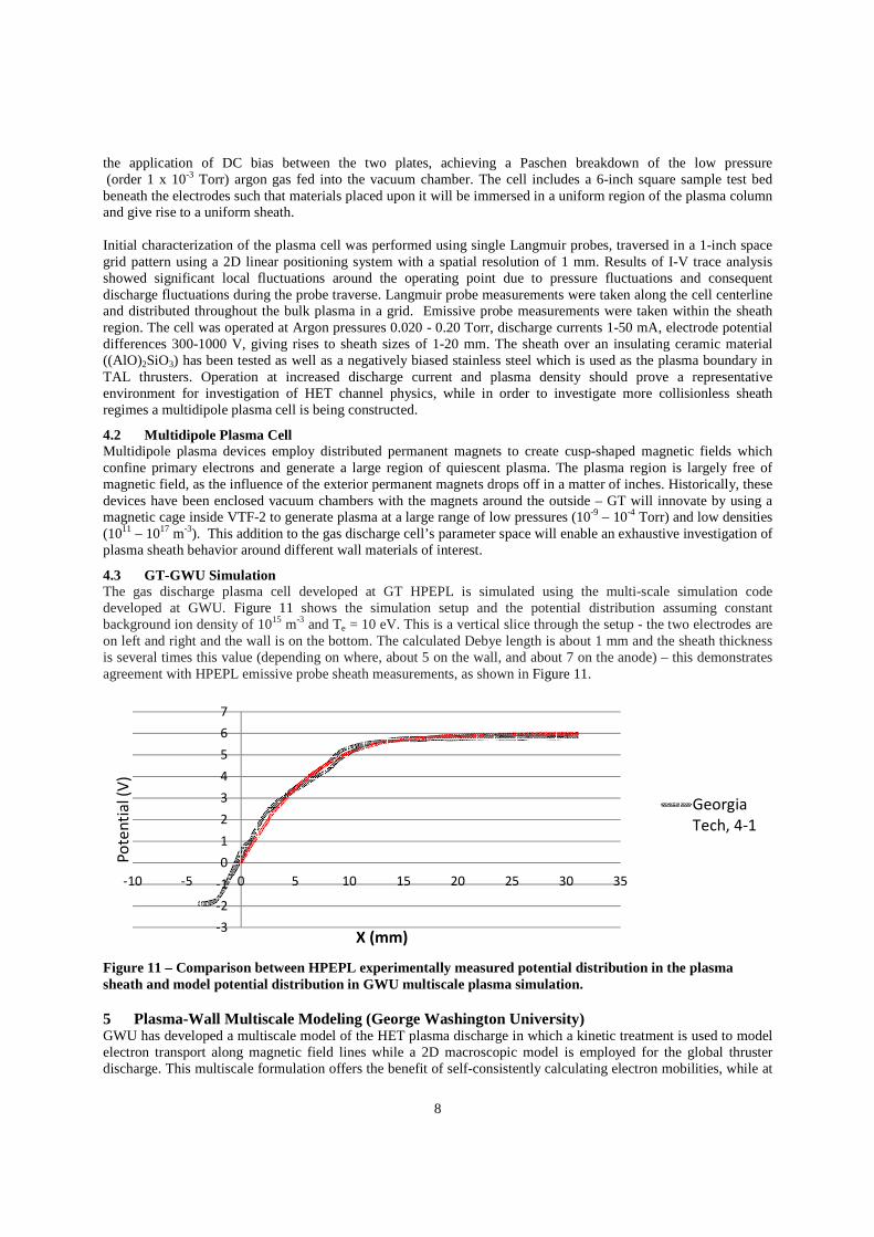
4.3 GT-GWU Simulation The gas discharge plasma cell developed at GT HPEPL is simulated using the multi-scale simulation code developed at GWU. Figure 11 shows the simulation setup and the potential distribution assuming constant background ion density of 1015 m-3 and Te = 10 eV. This is a vertical slice through the setup - the two electrodes are on left and right and the wall is on the bottom. The calculated Debye length is about 1 mm and the sheath thickness is several times this value (depending on where, about 5 on the wall, and about 7 on the anode) – this demonstrates agreement with HPEPL emissive probe sheath measurements, as shown in Figure 11.
Figure 11 – Comparison between HPEPL experimentally measured potential distribution in the plasma sheath and model potential distribution in GWU multiscale plasma simulation.
5 Plasma-Wall Multiscale Modeling (George Washington University) GWU has developed a multiscale model of the HET plasma discharge in which a kinetic treatment is used to model electron transport along magnetic field lines while a 2D macroscopic model is employed for the global thruster discharge. This multiscale formulation offers the benefit of self-consistently calculating electron mobilities, while at
-3
-2
-1
0
1
2
3
4
5
6
7
-10 -5 0 5 10 15 20 25 30 35
Po
ten
tia
l (V
)
X (mm)
Georgia
Tech, 4-1

9
the same time retaining the reduced computational requirements of a hybrid model. Initial coupling of the microscopic and macroscopic model is performed via axial electric field, electron fluxes to the wall and electron cross-field transport.
5.1 Multiscale Plasma Simulation Although a fully-kinetic approach, in which all species including electrons are treated kinetically, could resolve electron and wall effects directly, such an approach is not cost effective. Fully kinetic models are prohibitively slow and resource intensive, since details on the spatial scale of electrons must be resolved. Recently, progress has been made on tackling these computational difficulties by considering a multiscale approach to modeling HETs. We decompose the HET analysis into three spatial scales, each concentrating on a different subset of physics. A single magnetic field line serves as the first spatial scale, as shown in Figure 12a). On this spatial scale, dynamics are dominated by the microscopic cyclotron motion of electrons and their interaction with heavy particles and thruster walls; heavy particle densities and cross-field properties can be assumed to remain frozen. The simulation self-consistently calculates electron transport and velocity distribution evolution. Since the simulation is limited to a single magnetic field line, the computation is fast and hundreds of electron orbits can be computed in the matter of minutes. Utilizing multiple core architecture, multiple magnetic field lines can be analyzed in parallel. A 2D axial hybrid code forms the second domain in our multiscale model. It is illustrated in Figure 12b). Ion and neutral density is obtained by simulating kinetic particles. In our approach, the spatial variation in mobility is calculated self-consistently by the kinetic code. The microscopic and macroscopic models described above depend on each other. In order to obtain a truly self-consistent solution, the two codes are iterated until convergence. Once a converged solution has been reached, ion particles leaving the thruster can be sampled to obtain a discretized velocity distribution function for the thruster plume, which represents the third spatial scale of the model illustrated in Figure 12c).
Figure 12 – Schematic of multiscale approach. Kinetic model of the microscopic electron motion about magnetic field lines (a) is used to self-consistently calculate electron mobility. This mobility is then used in a hybrid 2D axial code for thruster discharge (b). Upon reaching steady state, ions exiting the thruster are sampled to obtain a source model for plume analysis (c).
5.1.1 Near-wall sheath formation The plasma-wall transition region in the HET channel determines the particle and energy fluxes from the plasma to the wall. For self-consistency, the boundary parameters at the sheath edge (ion velocity and electric field) have to be obtained from a multi-dimensional (in our case, two-dimensional) plasma bulk particle model. Having particle density, ion velocity distribution and electric field calculated from the bulk plasma particle model, the potential drop across the sheath can be calculated for given wall materials (specifically, secondary electron emission coefficients.) The relationship between the ion velocity and electric field at the plasma-sheath interface is shown in Figure 13. Including the sheath acceleration of the ions will increase the ability to predict wall erosion rates.
5.1.2 Secondary Electron Emission and Importance of Electron Thermalization Based on the steady state sheath condition we can calculate the potential drop across the sheath. These results are shown in Figure 14, where electron thermalization coefficient was used as a parameter. One can see that the higher

10
thermalization coefficient leads to reduced sheath potential drop and increased electron losses to the wall. A low thermalization coefficient restores the strong sheath, as in the case without SEE.
Figure 13 – Relationship between boundary conditions at the plasma-sheath interface. Electric field is normalized by Te/LD (LD is the Debye length) and velocity is normalized by the Bohm speed.
Figure 14 – Dependence of the sheath potentail drop on wall material SEE yield.
An additional effect of electron thermalization is on the global discharge characteristics such as the bulk electron temperature. To illustrate this effect a 2D quasi-neutral plasma flow domain was considered that has lateral boundaries near a dielectric wall. The electron energy equation and electron transport are considered along the centerline. The electron temperature is calculated along the centerline as a balance between Joule heating, ionization and wall losses. Partial electron thermalization is taken into account parametrically and it has a very strong effect on global discharge characteristics. As an example it is shown in Figure 15 that this effect changes peak electron temperature. It can be seen that higher electron thermalization leads to saturation of Te at higher discharge voltage while low electron thermalization produces near linear increase of Te with discharge voltage. This is a very important effect, particularly when high-power and high-voltage plasma discharges a
Figure 15 – Effect of the partial SEE electron thermalization on electron temperature. αααα=1 corresponds to complete thermalization.

Comprehensive Study of Plasma‐Wall Sheath Transport Phenomena
Jud ReadyPrincipal Research Engineer & Adjunct Prof.
Georgia Tech Research Institute
Gregory ThompsonProfessor
The University of Alabama
Michael KeidarAssociate Professor
George Washington University
Julian RimoliAssistant Professor
Georgia Institute of Technology
Mitchell Walker ‐ PIAssociate Professor
Georgia Institute of Technology
1
August 24, 2012

Introduction and Motivation
• Fundamental Science questions:1. How do insulator topology and composition alterations caused by erosion
effect sheath formation (path to equilibrium) and plasma dynamics?2. How does the plasma contribute to insulator erosion mechanisms?
• Ideal outcome is a set of relations and models which predict the four transport processes – enables plasma device design that use plasma‐wall interaction to enhance performance
2
Wall
Ions, Neutral Gas, Plasma Electrons, and Radiation
Ions, Neutral Gas, Plasma Electrons, Secondary Electrons, Wall Material, and Radiation
Conductive Heat Loss
Flow direction of particles and radiative energy to and from the wall.
The sheath drives the energy flux onto materials, which causes erosion and topology alterations. To understand the sheath, we must study the plasma and the wall transition.

3
Collaborative Team Structure and Integrated Data Flow Progression
Walker (GT)Plasma Sheath Experiment
Ready (GTRI)Accelerated insulator erosion experiments
Keidar (GWU)Plasma modeling
Rimoli (GT)Microstructure modeling
Thompson (UA)Materials
Characterization
Plasmaand sheathsimulation
Plasma parameters in plasma and sheath
•Particle fluxes•Ion energy•Heat flux
•Surface erosion rate•Surface morphology
Materials Characterization
Bi‐monthly telecoms + Quarterly face‐to‐face meetings
ModelResults
(erosion & morphology)

5 μm
5 μm
5 μm
Low Erosion
Mild Erosion
High Erosion
M26 Combat©60wt% BN ‐ 40wt%SiO2
Schematic of HET Discharge
UM/AFRL P5 HET1.5 – 5 kW Operation>2,000 hrsXenon Plasma
Erosion Microstructure under HET Xe Plasma

1
5 μm
D
Microstructure Erosion Patterns in Highly‐Eroded RegionSmooth planar silica surface –suggestive of micro‐scale BN detachment and weak interphase bonding
Jagged, surface protrusions – possible secondary electron emission sites? Possible spu er erosion mechanism→ modeling underdevelopment
Micro‐cracking prevalent in the BN phase• Parallel and along the basal plane• Believe to be from anisotropic thermal expansion of BN in amorphous silica matrix
• Ion implantation in a hcp BN phase verses more ‘open volume’ amorphous silica phase
Extracted TEM foil confirming phase identification and micro‐crack morphology in BN
10 keV secondary electron SEM micrograph

5 μm
Modeling Microstructure Erosion Patterns
Erosion striations
Erosion striations
XPS: preferential retention ofsilica in highly eroded region.Agreement with Garnier (1999),but not Zidar and Rovey (2011).(Binding energy of BN > silica).Detachment of BN in highlyeroded region is believed tocontribute to this observation
Directional, erosion striations possibly captured in sputter‐based erosion model•Models sputtering of a heterogeneous material•200x200 surface grid, 10x10x10 µm domain•Erosion rate model for each material derived from Yalin’s experimental sputtering data on HBC BN and quartz•1E18 xe/m3, 150 eV ion beam at 78° to surface normal•50% volume fraction of cylindrical 0.1 µm x 10 µm BN grains in a SiO2 matrix
BN model fiber construction

0.0E+005.0E‐061.0E‐051.5E‐052.0E‐052.5E‐053.0E‐05
‐10 90 190
RPA Cu
rren
t (A)
RPA Voltage (V)
Sample Normal to PlasmaPlasma Discharge: 80 V, 40 A8‐hour exposure (10 sccm Ar)
Plasma Source
0.0E+00
2.0E‐03
4.0E‐03
6.0E‐03
8.0E‐03
‐200 ‐100 0 100 200Langmuir P
robe
Measured
Curren
t (A)
Langmuir Probe Applied Voltage (V)
BN Sample Sample Holder
Plasma Characterization
IAD Chamber
Accelerated Erosion Studies to Quantify Mechanisms
• 50mm X 300mm rod,•Cut to 25mm x 25mm quarter circles, ~6.35mm thick sections
• Surfaces lathed to mimic thruster sheath surfaces• No qualitative differences between ‘As‐received’ and Prepared samples
Langmuir probe and RPA used to quantify the plasma flux conditions
Typical Chemical Analysis
Grade M26(BN-SiO2)
Boron 26.5-28.7%Nitrogen 32.8-35%Oxygen -Calcium .01%
Silica (SiO2) 40%Other Inorganic 0.05%Trace Metals 0.05%
TOTAL 100%B2O3 0.20%

Accelerated Plasma Erosion – Sample Exposure
Previous erosion microstructures (seen in HET) captured in controlled test!Provided means to control, monitor, and characterize specific regions to specific plasma conditions
Striations
“jagged” protrusions
Detachment of BN from silica
As Received, un‐cut M26 Prepared M26 Sample
Unexposed Boron Nitride

Plasma Sheath
‐3
‐2
‐1
0
1
2
3
4
5
6
7
‐10 ‐5 0 5 10 15 20 25 30 35
Potential (V)
X (mm)
Georgia Tech,4‐1
Simulation,n0=5e12,Te0=1.5,phi0=6
• Experimental characterization (number density and potential) of the argon plasma sheath (~10 mm) near insulators and conductors
• Comparison with multiscale plasma model
Bulk PlasmaSheath Region
ne ~ 1015 m‐3
• Continue to develop diagnostics in near‐wall region
• Integrate surface probe

1. Material characterization of HET eroded microstructure initiated • Microcracking prevalent in BN along basal plane• Erosion into jagged protrusions occur – implication to secondary electron
emission unclear• Detachment of BN from silica yielding preferential retention of silica during
erosion2. Controlled erosion chamber for accelerated studies set‐up and functioning3. Material Modeling
• MD simulation of erosion• Effects of material mesostructural heterogeneity on the development of the
surface profile4. Plasma
• Multiscale model of bulk plasma and sheath• Experimental characterization of plasma properties in thick sheath near
insulators and conductors5. Publications
• Joint Publication: "Plasma induced microstructure erosion in BN‐silica composite" ‐ In Progress
• Keidar – L. Brieda and M. Keidar, Sheath formation in an oblique magnetic field, J. Appl. Phys., vol. 111, 123302, 2012
• Keidar – L. Brieda and M. Keidar, Multiscale simulation of Hall thrusters, AIAA Joint Propulsion Conference, Atlanta GA, Aug., 2012.
Accomplishments – Year 1