comprehensive canal dredging and preventative measures
TRANSCRIPT
CCoommpprreehheennssiivvee CCaannaall DDrreeddggiinngg aanndd PPrreevveennttaattiivvee MMeeaassuurreess FFeeaassiibbiilliittyy SSttuuddyy ((CCCCDDPPMM))
IIddeennttiiffiiccaattiioonn ooff PPrroojjeecctt AArreeaass aanndd BBaacckkggrroouunndd IInnffoorrmmaattiioonn
PPrreeppaarreedd ffoorr::
HHiillllssbboorroouugghh CCoouunnttyy SSttoorrmmwwaatteerr MMaannaaggeemmeenntt SSeeccttiioonn
PPuubblliicc WWoorrkkss DDeeppaarrttmmeenntt
CCoonnttrraacctt NNoo.. 0033--11332222 WWoorrkk OOrrddeerr NNoo.. 0066--0033--11332222
PPrreeppaarreedd bbyy PPBBSS&&JJ
55330000 WWeesstt CCyypprreessss SSttrreeeett TTaammppaa,, FFlloorriiddaa 3333660077
FFeebbrruuaarryy 22000066
PBS&J Draft
Identification of Project Areas February 2006 And Background Information
i
EXECUTIVE SUMMARY Post, Buckley, Schuh and Jernigan, Inc. (PBS&J) was contracted in September 2005 by Hillsborough County to complete the Comprehensive Canal Dredging and Preventative Measures Feasibility (CCDPM) Study. The purpose of the CCDPM Study is to investigate known areas of concern throughout the unincorporated portions of the county in order to develop a plan to assess potential canal dredging needs. The study includes completing hydrographic/bathymetric surveys, habitat analysis, sediment sampling, water quality sampling, spoil disposal options, conceptual design, cost estimates, investigating funding options and identifying permitting potential. There are several interim reports required during the CCDPM Study. Each report represents the completion of a specific project milestone. This report represents the completion of the first deliverable, Identification of Project Areas and Background Information. Because of the continued growth in Hillsborough County, there has been an increased need to complete maintenance dredging in coastal residential canal communities in the unincorporated portions of the County. The County designated Canal Advisory Committee (CAC) was responsible for identifying the extent of each of the applicable project areas. As a result, eight project areas were identified throughout the County. These project areas were selected based on the functionality and navigability of coastal canals within each community. This report presents each of the selected study areas as defined by the CAC and provides the dredging history of each of the project areas. Documentation regarding any previous or historic permitting issued for each of the project areas was requested from the Tampa Port Authority, the Florida Department of Environmental Protection (FDEP), and the U.S. Army Corps of Engineers (ACOE). Permits have been received from the FDEP and the Tampa Port Authority for several of the project areas. To date, the ACOE has not provided any information or permits. Information is also included regarding property ownership, which was obtained from the County Property Appraiser office. This report also provides a general overview of possible contributing sources of sedimentation and presents a canals grouping system within each of the project areas. The County has involved local citizens in the planning process in order to identify primary areas of concern throughout the project areas. This type of interaction allows citizens to voice concerns regarding their particular project area and assist the investigation in focusing efforts to identify locations that require the greatest maintenance. To date, over 500 households have participated in the program.
PBS&J Draft
Identification of Project Areas February 2006 And Background Information
ii
TABLE OF CONTENTS
1.0 PURPOSE................................................................................................................ 1
2.0 IDENTIFICATION OF PROJECT AREAS ....................................................... 2
3.0 NORTH PROJECT AREAS.................................................................................. 4
3.1 Bayport Area........................................................................................................ 4
3.1.1 Previous Permit Activity .......................................................................... 4
3.1.2 Historic Aerials.......................................................................................... 5
3.1.3 Property Ownership ................................................................................. 5
3.1.4 Sedimentation............................................................................................ 5
3.1.5 Project Characterization .......................................................................... 6
3.2 Baycrest Area....................................................................................................... 6
3.2.1 Previous Permit Activity .......................................................................... 6
3.2.2 Historic Aerials.......................................................................................... 7
3.2.3 Property Ownership ................................................................................. 7
3.2.4 Sedimentation............................................................................................ 7
3.2.5 Project Characterization .......................................................................... 9
3.3 Essex Downs ......................................................................................................... 9
3.3.1 Previous Permit Activity .......................................................................... 9
3.3.2 Historic Aerials.......................................................................................... 9
3.3.3 Property Ownership ................................................................................. 9
3.3.4 Sedimentation............................................................................................ 9
3.3.5 Project Characterization ........................................................................ 11
3.4 Dana Shores........................................................................................................ 11
3.4.1 Previous Permit Activity ........................................................................ 11
3.4.2 Historic Aerials........................................................................................ 11
3.4.3 Property Ownership ............................................................................... 12
3.4.4 Sedimentation.......................................................................................... 12
3.4.5 Project Characterization ........................................................................ 13
4.0 SOUTH PROJECT AREAS ................................................................................ 14
4.1 Alafia Area ......................................................................................................... 14
PBS&J Draft
Identification of Project Areas February 2006 And Background Information
iii
4.1.1 Previous Permit Activity ........................................................................ 14
4.1.2 Historic Aerials........................................................................................ 14
4.1.3 Property Ownership ............................................................................... 14
4.1.4 Sedimentation.......................................................................................... 14
4.1.5 Project Characterization ........................................................................ 16
4.2 Apollo Beach North ........................................................................................... 16
4.2.1 Previous Permit Activity ........................................................................ 16
4.2.2 Historic Aerials........................................................................................ 17
4.2.3 Property Ownership ............................................................................... 17
4.2.4 Sedimentation.......................................................................................... 17
4.2.5 Project Characterization ........................................................................ 18
4.3 Apollo Beach South ........................................................................................... 18
4.3.1 Previous Permit Activity ........................................................................ 18
4.3.2 Historic Aerials........................................................................................ 19
4.3.3 Property Ownership ............................................................................... 19
4.3.4 Sedimentation.......................................................................................... 20
4.3.5 Project Characterization ........................................................................ 21
4.4 Ruskin................................................................................................................. 21
4.4.1 Previous Permit Activity ........................................................................ 21
4.4.2 Historic Aerials........................................................................................ 21
4.4.3 Property Ownership ............................................................................... 21
4.4.4 Sedimentation.......................................................................................... 22
4.4.5 Project Characterization ........................................................................ 23
REFERENCES: .............................................................................................................. 24
APPENDIX A: North Project Areas APPENDIX B: South Project Areas
PBS&J Draft
Identification of Project Areas February 2006 And Background Information
iv
LIST OF TABLES
Page Table 1. List of Project Areas 2
LIST OF FIGURES Page Figure 1. Project Location Map 3
PBS&J Draft
Identification of Project Areas February 2006 And Background Information
1
1.0 PURPOSE Post, Buckley, Schuh and Jernigan, Inc. (PBS&J) was contracted by Hillsborough County in September 2005 to complete the required professional engineering services for the Comprehensive Canal Dredging and Preventative Measures Feasibility (CCDPM) Study. Services performed under this work assignment include public communications, data collection, engineering analysis, preparation of several reports, and general support for county staff at various meetings. Hillsborough County Board of County Commissioners authorized the County Administrator to develop a study to address sedimentation within the coastal residential canal communities of the County. The County Public Work Department developed a scope of work for completing the CCDPM Study. The purpose of the CCDPM Study is to investigate known areas of concern throughout unincorporated portions of the County in order to develop a plan to assess potential canal dredging needs. The study includes completing hydrographic/bathymetric surveys, habitat analysis, sediment sampling, water quality sampling, spoil disposal options, conceptual design, cost estimates, investigating funding options and identifying permitting potential. The overall work assignment to complete the CCDPM Study includes the following tasks:
• Task I Project Management and Coordination • Task II Identification of Project Area and Background Information • Task III Field Investigation – Data Collection and Survey • Task IV Permitting Requirements • Task V Planning and Prevention Measures • Task VI Cost Estimates • Task VII Technical Alternatives Analysis • Task VIII Funding Alternatives Analysis • Task IX Public Involvement • Task X Project Recommendations • Task XI Preparation of Final Report
Within the scope of work for the CCDPM Study, there are several interim reports that are to be prepared as part of the overall work assignment. Each report represents the completion of a project milestone and constitutes finalized sections of the Final Report. This report represents the completion of the first deliverable, Identification of Project Areas and Background Information. This report presents each of the selected study areas as defined by the Canal Advisory Committee (CAC). The report also provides the dredging history of each of the project areas by collecting documentation from U.S. Army Corps of Engineers, Florida Department of Environmental Protection, Hillsborough County, Environmental Protection Commission, the Tampa Port Authority, the City of Tampa and other pertinent regulatory or governmental agencies.
PBS&J Draft
Identification of Project Areas February 2006 And Background Information
2
Documentation presented herein includes historic permits, aerials, and plans. This information will be used to aid in the completion of the permitting requirements report. This report identifys property ownership, public or private, from the County Property Appraiser office for submerged lands throughout the project areas. The report also provides a brief overview of possible contributing sources of sedimentation within each project area. The original intent of the report was to include an assessment of sediment loading, historic land use, and dredge maintenance records in order to provide a preliminary determination regarding the apportioning of sedimentation. Until the bathymetric survey and sediment sampling/testing is complete, the County has agreed to defer this section until the Sediment Sampling Interim Report where it is more appropriate and meaningful.
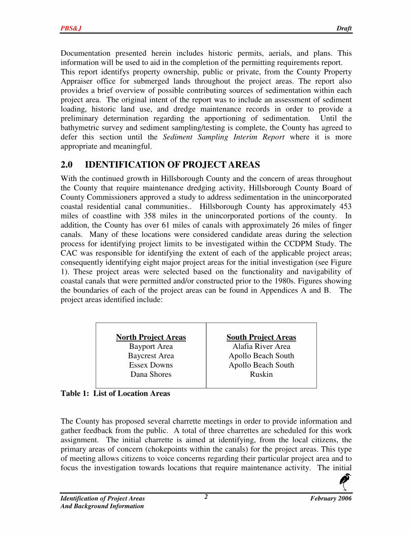
2.0 IDENTIFICATION OF PROJECT AREAS With the continued growth in Hillsborough County and the concern of areas throughout the County that require maintenance dredging activity, Hillsborough County Board of County Commissioners approved a study to address sedimentation in the unincorporated coastal residential canal communities.. Hillsborough County has approximately 453 miles of coastline with 358 miles in the unincorporated portions of the county. In addition, the County has over 61 miles of canals with approximately 26 miles of finger canals. Many of these locations were considered candidate areas during the selection process for identifying project limits to be investigated within the CCDPM Study. The CAC was responsible for identifying the extent of each of the applicable project areas; consequently identifying eight major project areas for the initial investigation (see Figure 1). These project areas were selected based on the functionality and navigability of coastal canals that were permitted and/or constructed prior to the 1980s. Figures showing the boundaries of each of the project areas can be found in Appendices A and B. The project areas identified include:
North Project Areas
Bayport Area Baycrest Area Essex Downs Dana Shores
South Project Areas
Alafia River Area Apollo Beach South Apollo Beach South
Ruskin
Table 1: List of Location Areas The County has proposed several charrette meetings in order to provide information and gather feedback from the public. A total of three charrettes are scheduled for this work assignment. The initial charrette is aimed at identifying, from the local citizens, the primary areas of concern (chokepoints within the canals) for the project areas. This type of meeting allows citizens to voice concerns regarding their particular project area and to focus the investigation towards locations that require maintenance activity. The initial
PBS&J Draft
Identification of Project Areas February 2006 And Background Information
3
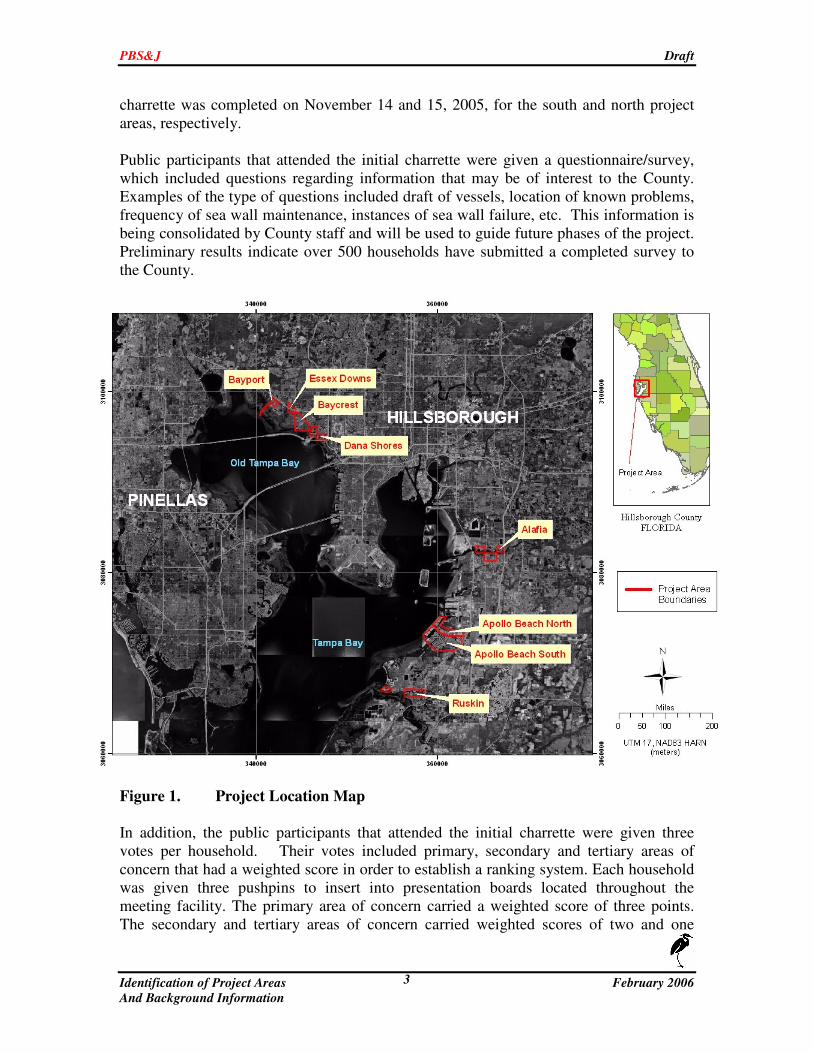
charrette was completed on November 14 and 15, 2005, for the south and north project areas, respectively. Public participants that attended the initial charrette were given a questionnaire/survey, which included questions regarding information that may be of interest to the County. Examples of the type of questions included draft of vessels, location of known problems, frequency of sea wall maintenance, instances of sea wall failure, etc. This information is being consolidated by County staff and will be used to guide future phases of the project. Preliminary results indicate over 500 households have submitted a completed survey to the County.
Figure 1. Project Location Map In addition, the public participants that attended the initial charrette were given three votes per household. Their votes included primary, secondary and tertiary areas of concern that had a weighted score in order to establish a ranking system. Each household was given three pushpins to insert into presentation boards located throughout the meeting facility. The primary area of concern carried a weighted score of three points. The secondary and tertiary areas of concern carried weighted scores of two and one
PBS&J Draft
Identification of Project Areas February 2006 And Background Information
4
points, respectively. The ranking system was used to statistically rank and separate community problem locations. The ranking system has provided the basis for identifying areas of concern within each of the project locations. The areas of concern were put in alphabetical order based on rank (total score) within each individual project area. In instances where two areas of concern received the same score, each area was given a numeric designation. The results for each of the eight project areas are located in Appendices A and B for the north and south project areas, respectively. A total of 167 preliminary areas of concern were identified through this process. This information will be coupled with the results of the bathymetric survey in order to finalize the boundaries within the project areas that have the greatest need for maintenance dredging. The following sections of the report provide information regarding the dredge history of each of the project areas resulting from documentation obtained from U.S. Army Corps of Engineers, Florida Department of Environmental Protection, Hillsborough County Environmental Protection Commission, the Tampa Port Authority, the City of Tampa and other regulatory agencies. Information regarding any previous or historic permitting issued for each of the project areas was requested from the Tampa Port Authority, the Florida Department of Environmental Protection (FDEP), and the U.S. Army Corps of Engineers (ACOE). Any previous or historic permitting will aid in determining the previously approved dredged configurations of canals and channels and would provide the dates that they were originally dredged. Permits were received directly from the FDEP and the Tampa Port Authority for several of the project areas. To date, the ACOE has not provided any information or permits. Additional information provided within the following sections includes historic aerials and property ownership, public or private, for submerged lands throughout the project areas. In addition, an overview of possible contributing sources of sedimentation is provided herein with a general characterization of each project area. All project areas boundaries, previous permit documentation, historical aerial overlays, and property ownership designations, that will accompany the remaining sections of the report, can be found in Appendices A and B.
3.0 NORTH PROJECT AREAS
3.1 Bayport Area
3.1.1 Previous Permit Activity
There were no permits for dredging or maintenance dredging activities located by FDEP, the Tampa Port Authority, or the ACOE for this project area.
PBS&J Draft
Identification of Project Areas February 2006 And Background Information
5
3.1.2 Historic Aerials
Interpretation of a historic aerial dated 1968, the majority of the Bayport project area appears to be created out of historic wetlands and uplands. The entrance channel appears to be dredged out of wetlands and leads from Hillsborough Bay to the inner canals. The canals located waterward of Imperial Key, Donbrese Avenue, Dowry Avenue, Drummond Road, and Baywater Drive appear to be created by the dredging of uplands.
3.1.3 Property Ownership
The submerged lands in the entrance channel, which were dredged out of wetlands, would likely be the property of the Tampa Port Authority and will require their authorization to perform dredging. The areas located within the manmade upland cut canals will need authorization from adjacent property owners of the submerged lands in order to conduct any dredging activity. Further documentation of submerged lands ownership may be required during the permitting process.
3.1.4 Sedimentation
As mentioned previously, this report provides an overview of possible contributing sources of sedimentation within each project area. Upon completion of the bathymetric survey and sediment sampling, an assessment of sediment apportionment will be presented in the Sediment Sampling Interim Report. As indicated by the historic aerials, Bayport has experienced rapid development over the past several decades. Development occurred along many of the manmade canals through the project area. Presently, there are only a few existing areas undeveloped along the waterway. Development along the finger canals is primarily residential with a few commercial properties interspersed. Bayport has been deteriorating through sediment accumulation over the past several years. In general, sediment accumulation is a result of a combination of processes. While there has not been a definitive study to determine all of the causes of the shoaling, the following processes have been or are currently active along the waterway.
1) Sediment resulting from commercial and residential development – During the last several years there has been rapid development along West Hillsborough Avenue. This includes the construction of several commercial properties and the development of several large residential sites. During construction, large rainstorms can transport sediment from cleared, unvegetated land and may contribute significant amounts of sediment into the project area over a short period.
2) Sediment transported from upstream – The Bayport project area lies on Channel
A. Channel A provides drainage for inland property several miles upstream and may transport sediment during high flow events directly from the upper reaches into the project area.
PBS&J Draft
Identification of Project Areas February 2006 And Background Information
6
3) Sediment erosion – There are several possible sources of sediment may enter
Bayport from within the waterway. Sediment may be eroded from the shoreline during periods of high water. Shore protection structures help minimize the amount of sediment that enters the system through erosion prevention. Some of the developed and undeveloped properties along Bayport have no shore protection structures, while other developed properties have various combinations of vertical bulkheads and sloping rock revetments.
4) Sediment from runoff – During high rainfall events, quantities of sediment wash
down from residential properties and from the adjacent canals. Sediments may also enter the system from runoff either directly or indirectly through drains and/or pipes.
5) Sediment from Tampa Bay- Ongoing research at the Institute for Marine Remote
Sensing at the University of South Florida provides information regarding the circulation and sediment loading throughout Tampa Bay. This information suggests that sediment sources within Tampa Bay may contribute to the sediment accumulation along the coastal waters of Hillsborough County.
6) Sediment derived from detritus – Sediments derived from decomposing vegetation
over time can produce large amounts of fine-grained materials and can be one of the dominant sources of sediment. Detritus can be introduced into the waterway directly thorough dumping, yard/property maintenance activities, or by natural causes. Various types of vegetation, which are introduced into the waterway, become saturated and sink. This material slowly decays and decomposes to become fine-grained sediment/mud along the bottom of the waterway. Natural sources of vegetation include mangroves, other large over-hanging trees, and other vegetation that grows along the banks of the waterway.
3.1.5 Project Characterization
At this point in the Study, as described in previous sections, canal systems have been characterized by historic development and current property ownership. Future phases of this work will include characterization regarding land use, sedimentation processes, and drainage patterns. Sediment sampling, design considerations, alternatives analysis, dredge techniques, permitting requirements, etc. will utilize these canal groupings to streamline future phases of work.
3.2 Baycrest Area
3.2.1 Previous Permit Activity
Several permits relating to maintenance dredging were located within the project boundaries for the Baycrest area. Those permits were recently issued by the Tampa Port Authority to maintenance dredge in the vicinity of the Spinnaker Cove docking facilities.
PBS&J Draft
Identification of Project Areas February 2006 And Background Information
7
These permits were issued on June 24, 2005 for the maintenance dredging of approximately 8,200 cubic yards of material to a depth of 5.5 feet below mean low water. The Port’s permit file also included a copy of the Southwest Florida Water Management District exemption dated March 23, 2005 for the same project.
3.2.2 Historic Aerials
Aerial interpretation revealed the southern portion of Spinnaker Cove, along with the upland area associated with Bay Pointe Drive and Causeway Vista Drive, were created by filling in natural portions of wetlands. Based on the aerial interpretation, these areas were created by dredging the wetlands and using the spoil material to create fill areas, which later became the uplands that are currently developed. The remaining canals appear to be dredged out of uplands. Due to low resolution of the 1938 aerial, the determination of whether the canals located adjacent to Palisades Drive, Cobblestone Drive, and Flagstone Drive were upland cut is inconclusive. However, the historic aerials do indicate that the entire Baycrest area was artificially created either through the dredging of wetlands or uplands to create a series of canal systems that are evident today.
3.2.3 Property Ownership
Except for the areas that are privately owned as indicated by the Hillsborough County Property Appraisers Office, there is no clear record of ownership of the bottom lands within the canal system. Most likely, the Tampa Port Authority would claim ownership to these bottom lands outside the basin adjacent to the Spinnaker Cove Townhomes and the residential canals (Hillsborough Bay). Those bottom lands that are privately owned would require written consent from those property owners to conduct maintenance dredging. In most cases, the submerged lands within the canals are owned by the property owners of the adjacent uplands. Further documentation of submerged lands ownership may be required during the permitting process.
3.2.4 Sedimentation
As mentioned previously, this report provides an overview of possible contributing sources of sedimentation within each project area. Upon completion of the bathymetric survey and sediment sampling an assessment of sediment apportionment will be presented in the Sediment Sampling Interim Report. As indicated by the historic aerials, Baycrest has experienced rapid development over the past several decades. Development occurred along many of the manmade canals through the project area. Presently, there are only a few existing areas undeveloped along the waterway. Development along the finger canals is primarily residential with a few commercial properties interspersed. Baycrest has been deteriorating through sediment accumulation over the past several years. In general, sediment accumulation is a result of a combination of processes. While there has not been a definitive study to determine all of the causes of the shoaling, the following processes have been or are currently active along the waterway.
PBS&J Draft
Identification of Project Areas February 2006 And Background Information
8
1) Sediment resulting from commercial and residential development – During the
last several years there has been rapid development along Memorial Highway and West Hillsborough Avenue. This includes the construction of several commercial properties and the development of several large residential sites. During construction, large rainstorms can transport sediment from cleared unvegetated land and may contribute significant amounts of sediment into the project area over a short period.
2) Sediment transported from upstream – The Baycrest project area lies on a
conveyance channel for stormwater. This channel as well as other contributing waterways (i.e. Rock Creek) provide drainage for inland property upstream and may transport sediment during high flow events directly into the project area.
3) Sediment erosion – There are several possible sources of sediment may enter
Baycrest from within the waterway. Sediment may be eroded from the shoreline during periods of high water. Shore protection structures help minimize the amount of sediment that enters the system through erosion prevention. Some of the developed and undeveloped properties along Baycrest have no shore protection structures; while other developed properties have various combinations of vertical bulkheads and sloping rock revetments.
4) Sediment from runoff – During high rainfall events, quantities of sediment wash
down from residential properties and from the adjacent canals. Sediments may also enter the system from runoff either directly or indirectly through drains and/or pipes.
5) Sediment from Tampa Bay- Ongoing research at the Institute for Marine Remote
Sensing at the University of South Florida provides information regarding the circulation and sediment loading through Tampa Bay. This information suggests that sediment sources within Tampa Bay may contribute to the sediment accumulation along the coastal waters of Hillsborough County.
6) Sediment derived from detritus – Sediments derived from decomposing vegetation
over time can produce large amounts of fine-grained materials and can be one of the dominant sources of sediment. Detritus can be introduced into the waterway directly thorough dumping, yard/property maintenance activities, or by natural causes. Various types of vegetation drop into the waterway, become saturated, and sink. This material slowly decays and decomposes to become fine-grained sediment/mud along bottom of the waterway. Natural sources of vegetation include mangroves and other large over-hanging types of trees and vegetation that grow along the banks of the waterway.
PBS&J Draft
Identification of Project Areas February 2006 And Background Information
9
3.2.5 Project Characterization
At this point in the Study, as described in previous sections, canal systems have been characterized by historic development and current property ownership. Future phases of this work will include characterization regarding land use, sedimentation processes, and drainage patterns. Sediment sampling, design considerations, alternatives analysis, dredge techniques, permitting requirements, etc. will utilize these canal groupings to streamline future phases of work.
3.3 Essex Downs
3.3.1 Previous Permit Activity
There were no permits for dredging or maintenance dredging activities located by FDEP, the Port, or the ACOE for this project area.
3.3.2 Historic Aerials
The project area appears to be created by the straightening of a preexisting meandering creek that ran through Essex Downs. The 1938 aerial does not reveal any existing infrastructure or development in the Essex Downs project area. There are several upland cut canals within the project area that were connected to the existing surface water or to its associated wetlands. Upland cut canals are located east of Sussex Drive, Coventry Drive, Portsmouth Drive, and Liverpool Drive. Additional upland cut canals are located north of Audrey Lane, South Lagoon Street, and Rocky Creek Drive.
3.3.3 Property Ownership
As determined by the Hillsborough County Property Appraisers Office, the southern portion of the project area consists of marsh and submerged lands is entirely owned by Hillsborough County. The ownership of the remaining submerged land is not clear. Additional research may be required to verify ownership during the permitting process. Any portion of the submerged land that is determined to be privately owned will require written authorization to conduct any dredging from the property owner prior to any dredging activity. Further documentation of submerged lands ownership may be required during the permitting process.
3.3.4 Sedimentation
As mentioned previously, this report provides an overview of possible contributing sources of sedimentation within each project area. Upon completion of the bathymetric survey and sediment sampling an assessment of sediment apportionment will be presented in the Sediment Sampling Interim Report. As indicated by the historic aerials, Essex Downs has experienced rapid development over the past several decades. Development occurred along many of the manmade canals through the project area. Presently, there are only a few existing areas undeveloped along the waterway. Development along the finger canals is primarily residential with a few commercial properties interspersed.
PBS&J Draft
Identification of Project Areas February 2006 And Background Information
10
Essex Downs has been deteriorating through sediment accumulation over the past several years. In general, sediment accumulation is a result of a combination of processes. While there has not been a definitive study to determine all of the causes of the shoaling, the following processes have been or are currently active along the waterway.
1) Sediment resulting from commercial and residential development – During the last several years there has been rapid development along West Hillsborough Avenue. This includes the construction of several commercial properties and the development of several large residential sites. During construction, large rainstorms can transport sediment from cleared unvegetated land and may contribute significant amounts of sediment into the project area over a short period.
2) Sediment transported from upstream – The Essex Downs project area lies on a
conveyance channel for stormwater. This channel as well as other contributing waterways provide drainage for inland property upstream and may transport sediment during high flow events directly into the project area.
3) Sediment erosion – There are several possible sources of sediment may enter
Essex Downs from within the waterway. Sediment may be eroded from the shoreline during periods of high water. Shore protection structures help minimize the amount of sediment that enters the system through erosion prevention. Some of the developed and undeveloped properties along Essex Downs have no shore protection structures; while other developed properties have various combinations of vertical bulkheads and sloping rock revetments.
4) Sediment from runoff – During high rainfall events, quantities of sediment wash
down from residential properties and from the adjacent canals. Sediments may also enter the system from runoff either directly or indirectly through drains and/or pipes.
5) Sediment from Tampa Bay- Ongoing research at the Institute for Marine Remote
Sensing at the University of South Florida provides information regarding the circulation and sediment loading through Tampa Bay. This information suggests that sediment sources within Tampa Bay may contribute to the sediment accumulation along the coastal waters of Hillsborough County.
6) Sediment derived from detritus – Sediments derived from decomposing vegetation
over time can produce large amounts of fine-grained materials and can be one of the dominant sources of sediment. Detritus can be introduced into the waterway directly thorough dumping, yard/property maintenance activities, or by natural causes. Various types of vegetation drop into the waterway, become saturated, and sink. This material slowly decays and decomposes to become fine-grained sediment/mud along bottom of the waterway. Natural sources of vegetation
PBS&J Draft
Identification of Project Areas February 2006 And Background Information
11
include mangroves and other large over-hanging types of trees and vegetation that grow along the banks of the waterway.
3.3.5 Project Characterization
At this point in the Study, as described in previous sections, canal systems have been characterized by historic development and current property ownership. Future phases of this work will include characterization regarding land use, sedimentation processes, and drainage patterns. Sediment sampling, design considerations, alternatives analysis, dredge techniques, permitting requirements, etc. will utilize these canal groupings to streamline future phases of work.
3.4 Dana Shores
3.4.1 Previous Permit Activity
There were no permits for dredging or maintenance dredging activities for this area provided by the FDEP, the Tampa Port Authority, or the ACOE. However, a relevant report was provided by a local resident regarding Sweetwater Creek. The “Report on the Silt Situation in Sweetwater Creek South of Memorial Bridge” was written and compiled by Jack Berlin, a local resident, in August 1998. The report includes documentation that the Sweetwater Creek area has been receiving large amounts of silt from offsite stormwater runoff, which was causing sedimentation within the Sweetwater Creek system. Based on statements from eye-witnesses that were included in the report, the Sweetwater Creek canals were dredged in 1995 to improved drainage. However, the statements were not signed affidavits and may not be able to be used as evidence of recent maintenance dredging. In addition, there was no documentation of having requested or received any authorization from any of the regulatory agencies to conduct dredging. The report also included unsurveyed water depths from 1998 along certain portions of the creek. This information may prove useful in future permitting efforts.
3.4.2 Historic Aerials
Aerial interpretation of the Dana Shores project area revealed large amount of dredging and filling occurred to create the current shoreline. The majority of the canals and uplands were artificially created by dredging and filling in wetlands and surface waters. The uplands peninsulas associated with Sweetwater Boulevard, Pelican Island Drive, Bonaventure Drive, and North Rocky Point Drive East were entirely created by dredging and filling in Hillsborough Bay and associated wetlands. Americana Drive, Versailles Drive and Fontainebleau Drive were partially dredge and filled out of wetlands to create uplands. The canals that are adjacent to Wedenroc Circle, Eldenroc Circle, Venetian Way, and Doral Drive were created by dredging uplands.
PBS&J Draft
Identification of Project Areas February 2006 And Background Information
12
3.4.3 Property Ownership
A review of the property ownership from the Hillsborough County Property Appraiser’s website of the submerged lands indicated the entire project area is privately owned. The canals between Versailles Drive and Fontainebleau Drive, Fontainebleau Drive and Wedenroc Circle, Eldenroc Circle and Venetian Way, Venetian Way and Doral Drive, and the canal immediately east of Doral Way is likely privately owned by the property owners that are immediately upland of the canal. Property boundaries are shown extending out to the center of each canal. The remainder of the submerged land in the Dana Shores project area was sold to private individuals on December 20, 1999. The property owners for those areas will need to provide authorization to perform maintenance dredging. Further documentation of submerged lands ownership may be required during the permitting process.
3.4.4 Sedimentation
As mentioned previously, this report provides an overview of possible contributing sources of sedimentation within each project area. Upon completion of the bathymetric survey and sediment sampling an assessment of sediment apportionment will be presented in the Sediment Sampling Interim Report. As indicated by the historic aerials, Dana Shores has experienced rapid development over the past several decades. Development occurred along many of the manmade canals through the project area. Presently, there are only a few existing areas undeveloped along the waterway. Development along the finger canals is primarily residential with a few commercial properties interspersed. Dana Shores has been deteriorating through sediment accumulation over the past several years. In general, sediment accumulation is a result of a combination of processes. While there has not been a definitive study to determine all of the causes of the shoaling, the following processes have been or are currently active along the waterway.
1) Sediment resulting from commercial and residential development – During the last several years there has been rapid development along Memorial Highway and Independence Parkway. This includes the construction of several commercial properties and the development of several large residential developments. During construction, large rainstorms can transport sediment from cleared unvegetated land and may contribute significant amounts of sediment into the project area over a short period.
2) Sediment transported from upstream – The Dana Shores project area lies on a
conveyance channel for stormwater, primarily on the western side of the project area. This channel as well as other contributing waterways provide drainage for inland property upstream and may transport sediment during high flow events directly into the project area.
PBS&J Draft
Identification of Project Areas February 2006 And Background Information
13
3) Sediment erosion – There are several possible sources of sediment may enter Dana Shores from within the waterway. Sediment may be eroded from the shoreline during periods of high water. Shore protection structures help minimize the amount of sediment that enters the system through erosion prevention. Some of the developed and undeveloped properties along Dana Shores have no shore protection structures; while other developed properties have various combinations of vertical bulkheads and sloping rock revetments.
4) Sediment from runoff – During high rainfall events, quantities of sediment wash
down from residential properties and from the adjacent canals. Sediments may also enter the system from runoff either directly or indirectly through drains and/or pipes.
5) Sediment from Tampa Bay- Ongoing research at the Institute for Marine Remote
Sensing at the University of South Florida provides information regarding the circulation and sediment loading through Tampa Bay. This information suggests that sediment sources within Tampa Bay may contribute to the sediment accumulation along the coastal waters of Hillsborough County.
6) Sediment derived from detritus – Sediments derived from decomposing vegetation
over time can produce large amounts of fine-grained materials and can be one of the dominant sources of sediment. Detritus can be introduced into the waterway directly thorough dumping, yard/property maintenance activities, or by natural causes. Various types of vegetation drop into the waterway, become saturated, and sink. This material slowly decays and decomposes to become fine-grained sediment/mud along bottom of the waterway. Natural sources of vegetation include mangroves and other large over-hanging types of trees and vegetation that grow along the banks of the waterway.
3.4.5 Project Characterization
At this point in the Study, as described in previous sections, canal systems have been characterized by historic development and current property ownership. Future phases of this work will include characterization regarding land use, sedimentation processes, and drainage patterns. Sediment sampling, design considerations, alternatives analysis, dredge techniques, permitting requirements, etc. will utilize these canal groupings to streamline future phases of work.
PBS&J Draft
Identification of Project Areas February 2006 And Background Information
14
4.0 SOUTH PROJECT AREAS
4.1 Alafia Area
4.1.1 Previous Permit Activity
There were no permits for dredging or maintenance dredging activities located by FDEP, the Port, or the ACOE for this project area.
4.1.2 Historic Aerials
The Alafia project area along the river appears to be relatively natural with minimal shoreline alteration as compared to the other areas within the project boundaries. Based on aerial interpretation of a series of historic aerials dated 1938 to 1968, there were a few canals that were created artificially between 1957 and 1968. The dredged canals along the southern shore of the Alafia River are located adjacent to Bay Drive, Peninsular Drive, River Drive, Alavista Drive, and Linda Street. The dredged canals located along the northern shore are adjacent to Oak Street and E. Millpoint Road. These canals appear to be dredged out of wetlands. Certain areas of land that show characteristics of being wetlands on the 1938 aerial lose those characteristics by 1957. This may indicate that these areas were either drained or filled to create uplands. The remaining shoreline appears to be natural through the present day.
4.1.3 Property Ownership
The submerged land within the Alafia River would be considered sovereign and therefore controlled by the Tampa Port Authority. Only those areas that are located in artificial canals, such as the canals previously discussed would be privately owned. Artificial canals would require authorization from property owners to perform maintenance dredging. Further documentation of submerged lands ownership may be required during the permitting process.
4.1.4 Sedimentation
As mentioned previously, this report provides an overview of possible contributing sources of sedimentation within each project area. Upon completion of the bathymetric survey and sediment sampling an assessment of sediment apportionment will be presented in the Sediment Sampling Interim Report. As indicated by the historic aerials, Alafia has experienced rapid development over the past several decades. Development occurred along many of the manmade canals through the project area. Presently, there are only a few existing areas undeveloped along the waterway. Development along the finger canals is primarily residential with a few commercial properties interspersed.
PBS&J Draft
Identification of Project Areas February 2006 And Background Information
15
Alafia has been deteriorating through sediment accumulation over the past several years. In general, sediment accumulation is a result of a combination of processes. While there has not been a definitive study to determine all of the causes of the shoaling, the following processes have been or are currently active along the waterway.
1) Sediment resulting from commercial and residential development – During the last several years there has been rapid development along Riverview Drive and Gibsonton Drive. This includes the construction of several commercial properties and the development of several large residential sites. During construction, large rainstorms can transport sediment from cleared unvegetated land and may contribute significant amounts of sediment into the project area over a short period.
2) Sediment transported from upstream – The Alafia project area is broken into three
reaches and lies on the Alafia River. The Alafia River provides drainage for inland property several miles upstream and may transport sediment during high flow events directly from the upper reaches and adjacent portions of the river into the project area.
3) Sediment erosion – There are several possible sources of sediment may enter
Alafia from within the waterway. Sediment may be eroded from the shoreline during periods of high water. Shore protection structures help minimize the amount of sediment that enters the system through erosion prevention. Some of the developed and undeveloped properties along Alafia have no shore protection structures; while other developed properties have various combinations of vertical bulkheads and sloping rock revetments.
4) Sediment from runoff – During high rainfall events, quantities of sediment wash
down from residential properties and from the adjacent canals. Sediments may also enter the system from runoff either directly or indirectly through drains and/or pipes.
5) Sediment from Tampa Bay- Ongoing research at the Institute for Marine Remote
Sensing at the University of South Florida provides information regarding the circulation and sediment loading through Tampa Bay. This information suggests that sediment sources within Tampa Bay may contribute to the sediment accumulation along the coastal waters of Hillsborough County.
6) Sediment derived from detritus – Sediments derived from decomposing vegetation
over time can produce large amounts of fine-grained materials and can be one of the dominant sources of sediment. Detritus can be introduced into the waterway directly thorough dumping, yard/property maintenance activities, or by natural causes. Various types of vegetation drop into the waterway, become saturated, and sink. This material slowly decays and decomposes to become fine-grained sediment/mud along bottom of the waterway. Natural sources of vegetation
PBS&J Draft
Identification of Project Areas February 2006 And Background Information
16
include mangroves and other large over-hanging types of trees and vegetation that grow along the banks of the waterway.
4.1.5 Project Characterization
At this point in the Study, as described in previous sections, canal systems have been characterized by historic development and current property ownership. Future phases of this work will include characterization regarding land use, sedimentation processes, and drainage patterns. Sediment sampling, design considerations, alternatives analysis, dredge techniques, permitting requirements, etc. will utilize these canal groupings to streamline future phases of work.
4.2 Apollo Beach North
4.2.1 Previous Permit Activity
The Tampa Port Authority located a copy of a permit for maintenance dredging around the hammerhead of Apollo Beach. This permit was issued by Port staff in 1995 for the maintenance dredging of the main access channels. As it relates to this project area, the permit authorizes the maintenance dredging of the “North Channel” to a depth of 7 feet below mean low water. The authorized maintenance dredging was 1,200 feet long and 40 feet wide. A local resident provided the most extensive documentation for the creation of Apollo Beach. A timeline of ACOE permitting and compliance history regarding Apollo Beach from 1959 to 1972 was included in the information and is relevant for both the north and south Apollo project areas. The permitting and compliance timeline indicates that the original permit request for the creation of Apollo Beach was on April 20, 1959. The permit for the dredging and filling of Tampa Bay in association with the Apollo Beach Subdivisions was issued on April 21, 1959. That permit was then modified for additional work on March 13, 1968. The original permit authorized the dredging and filling of Tampa Bay to create the filled uplands that now form the hammerhead. The modifications to the permit involved creating the internal canals and additional uplands. In 1966, a letter was provided to the ACOE that indicated “the entire Apollo Beach Subdivision including the upland canals, with certain exceptions, had either been completed or were partially completed.” The majority of the remaining canals appear to be created through 1969. Drawings of the original dredging proposal were included with the documentation for the permitting history. The original permit drawings, dated May 1959, indicated the location of the dredge area with a proposed dredge depth of 15 feet below mean low water. The original dredge configuration was provided but the documentation does not include any as-built information that provides the actual amount of dredging that occurred and therefore, there is no formal record that the authorized depth was achieved.
PBS&J Draft
Identification of Project Areas February 2006 And Background Information
17
4.2.2 Historic Aerials
Based on aerial interpretation, all canals east of Bimini Court in the Apollo Beach- north project area are upland cut. Canals and channels west of Bimini Court were dredged out of wetlands or surface waters. The only aerials available were those from 1938, during which time there was no earthwork or dredging being conducted.
4.2.3 Property Ownership
Through several transactions with the State of Florida, Board of Trustees of the Internal Improvement Trust Fund, the formerly sovereign submerged lands in Apollo Beach were deeded to private owners. The Tampa Port Authority would have control over those lands outside the deeds issued by the State. Authorization from private property owners to maintenance dredge is required. Further documentation of submerged lands ownership may be required during the permitting process.
4.2.4 Sedimentation
As mentioned previously, this report provides an overview of possible contributing sources of sedimentation within each project area. Upon completion of the bathymetric survey and sediment sampling an assessment of sediment apportionment will be presented in the Sediment Sampling Interim Report. As indicated by the historic aerials, Apollo Beach North has experienced rapid development over the past several decades. Development occurred along many of the manmade canals through the project area. Presently, there are only a few existing areas undeveloped along the waterway. Development along the finger canals is primarily residential with a few commercial properties interspersed. Apollo Beach North has been deteriorating through sediment accumulation over the past several years. In general, sediment accumulation is a result of a combination of processes. While there has not been a definitive study to determine all of the causes of the shoaling, the following processes have been or are currently active along the waterway.
1) Sediment resulting from commercial and residential development – During the last several years there has been rapid development along Apollo Beach and U.S. Highway 41. This includes the construction of several commercial properties and the development of several large residential developments. During construction, large rainstorms can transport sediment from cleared unvegetated land and may contribute significant amounts of sediment into the project area over a short period.
2) Sediment transported from upstream – The Apollo Beach North project area lies
on several conveyance channels for stormwater. These channels provide drainage for inland property upstream and may transport sediment during high flow events directly into the project area.
PBS&J Draft
Identification of Project Areas February 2006 And Background Information
18
3) Sediment erosion – There are several possible sources of sediment may enter
Apollo Beach North from within the waterway. Sediment may be eroded from the shoreline during periods of high water. Shore protection structures help minimize the amount of sediment that enters the system through erosion prevention. Some of the developed and undeveloped properties along Apollo Beach North have no shore protection structures; while other developed properties have various combinations of vertical bulkheads and sloping rock revetments.
4) Sediment from runoff – During high rainfall events, quantities of sediment wash
down from residential properties and from the adjacent canals. Sediments may also enter the system from runoff either directly or indirectly through drains and/or pipes.
5) Sediment from Tampa Bay- Ongoing research at the Institute for Marine Remote
Sensing at the University of South Florida provides information regarding the circulation and sediment loading through Tampa Bay. This information suggests that sediment sources within Tampa Bay may contribute to the sediment accumulation along the coastal waters of Hillsborough County.
6) Sediment derived from detritus – Sediments derived from decomposing vegetation
over time can produce large amounts of fine-grained materials and can be one of the dominant sources of sediment. Detritus can be introduced into the waterway directly thorough dumping, yard/property maintenance activities, or by natural causes. Various types of vegetation drop into the waterway, become saturated, and sink. This material slowly decays and decomposes to become fine-grained sediment/mud along bottom of the waterway. Natural sources of vegetation include mangroves and other large over-hanging types of trees and vegetation that grow along the banks of the waterway.
4.2.5 Project Characterization
At this point in the Study, as described in previous sections, canal systems have been characterized by historic development and current property ownership. Future phases of this work will include characterization regarding land use, sedimentation processes, and drainage patterns. Sediment sampling, design considerations, alternatives analysis, dredge techniques, permitting requirements, etc. will utilize these canal groupings to streamline future phases of work.
4.3 Apollo Beach South
4.3.1 Previous Permit Activity
Two permits were located by the Tampa Port Authority for this project area. The FDEP located one permit. The ACOE permit timeline (discussed in Apollo Beach- north) also applies to the southern portion of Apollo Beach.
PBS&J Draft
Identification of Project Areas February 2006 And Background Information
19
The Tampa Port Authority issued a permit to conduct maintenance dredging for the main access channels in 1995 as previously discussed. The channels associated with this project area are the “Main Channel” and two areas of the southern channel described as “South Channel (north) and “South Channel (south)”. The “Main Channel” was authorized to be maintenance dredged to approximately 1,425 feet in length by 60 feet in width. The authorized dredge depth for this channel was 8.0 feet below mean low water. The authorized configuration for “South Channel” north and south was 630 feet in length with varying widths from 20 feet to 60 feet. The final authorized dredge depth for the “South Channel” was 7.0 feet below mean low water. A second permit was issued for the Apollo Beach project area in 1995 by the Tampa Port Authority. This permit authorized maintenance dredging of the “Main Channel” and the “South Channel” from the entrance channel adjacent to Symphony Beach Lane to Eagle Lane. The permit authorized a final dredge depth of 5.0 feet below mean low water. Some of this maintenance dredging overlapped the previously mentioned permitted dredge; however, this project included maintenance dredging of the inner canals rather than those in Tampa Bay. The FDEP provided one permit issued on June 18, 1998, which was a modification of the original permit for the Symphony Isles Homeowners Association. The permit modification authorized the maintenance dredging of 900 cubic yards of material from the north entrance to the Symphony Isles subdivision. There is a discrepancy between the approved project drawings and the permit modification. The drawings that were included in the permit modification indicated a proposed dredge depth of 8 feet below mean low water, but the permit modification only authorizes dredging to a final depth of 5.0 feet below mean low water. There was no indication that an as-built survey was conducted to document the final dredge depth.
4.3.2 Historic Aerials
Based on aerial interpretation, the majority of the Apollo Beach canal system appears to be dredged out of wetlands or surface waters. The 1948 aerial indicates the upland areas were historically used as farmland and large areas of wetlands existed that were likely mangrove forest with marsh systems. As the ACOE permit timeline suggests, the majority of the Apollo Beach system of canals and fill islands were completed by 1968. The canals adjacent to Symphony Beach Lane, Piano Lane, Capriccio Lane, Symphony Isles Boulevard, Sonata Lane, and Allegro Lane were created after 1968.
4.3.3 Property Ownership
As previously discussed in Apollo Beach – north section, the Board of Trustees of the Internal Improvement Trust Fund deeded the submerged lands in Apollo Beach to private owners. The Tampa Port Authority would have control over those lands outside the state issued deeds. Those areas that are privately owned would need permission from the property owners to perform maintenance dredging. Further documentation of submerged lands ownership may be required during the permitting process.
PBS&J Draft
Identification of Project Areas February 2006 And Background Information
20
4.3.4 Sedimentation
As mentioned previously, this report provides an overview of possible contributing sources of sedimentation within each project area. Upon completion of the bathymetric survey and sediment sampling an assessment of sediment apportionment will be presented in the Sediment Sampling Interim Report. As indicated by the historic aerials, Apollo Beach North has experienced rapid development over the past several decades. Development occurred along many of the manmade canals through the project area. Presently, there are only a few existing areas undeveloped along the waterway. Development along the finger canals is primarily residential with a few commercial properties interspersed. Apollo Beach South has been deteriorating through sediment accumulation over the past several years. In general, sediment accumulation is a result of a combination of processes. While there has not been a definitive study to determine all of the causes of the shoaling, the following processes have been or are currently active along the waterway.
1) Sediment resulting from commercial and residential development – During the last several years there has been rapid development along Apollo Beach and U.S. Highway 41. This includes the construction of several commercial properties and the development of several large residential developments. During construction, large rainstorms can transport sediment from cleared unvegetated land and may contribute significant amounts of sediment into the project area over a short period.
2) Sediment transported from upstream – The Apollo Beach South project area lies
on several conveyance channels for stormwater. These channels provide drainage for inland property upstream and may transport sediment during high flow events directly into the project area.
3) Sediment erosion – There are several possible sources of sediment may enter
Apollo Beach South from within the waterway. Sediment may be eroded from the shoreline during periods of high water. Shore protection structures help minimize the amount of sediment that enters the system through erosion prevention. Some of the developed and undeveloped properties along Apollo Beach South have no shore protection structures; while other developed properties have various combinations of vertical bulkheads and sloping rock revetments.
4) Sediment from runoff – During high rainfall events, quantities of sediment wash
down from residential properties and from the adjacent canals. Sediments may also enter the system from runoff either directly or indirectly through drains and/or pipes.
PBS&J Draft
Identification of Project Areas February 2006 And Background Information
21
5) Sediment from Tampa Bay- Ongoing research at the Institute for Marine Remote Sensing at the University of South Florida provides information regarding the circulation and sediment loading through Tampa Bay. This information suggests that sediment sources within Tampa Bay may contribute to the sediment accumulation along the coastal waters of Hillsborough County.
6) Sediment derived from detritus – Sediments derived from decomposing vegetation
over time can produce large amounts of fine-grained materials and can be one of the dominant sources of sediment. Detritus can be introduced into the waterway directly thorough dumping, yard/property maintenance activities, or by natural causes. Various types of vegetation drop into the waterway, become saturated, and sink. This material slowly decays and decomposes to become fine-grained sediment/mud along bottom of the waterway. Natural sources of vegetation include mangroves and other large over-hanging types of trees and vegetation that grow along the banks of the waterway.
4.3.5 Project Characterization
At this point in the Study, as described in previous sections, canal systems have been characterized by historic development and current property ownership. Future phases of this work will include characterization regarding land use, sedimentation processes, and drainage patterns. Sediment sampling, design considerations, alternatives analysis, dredge techniques, permitting requirements, etc. will utilize these canal groupings to streamline future phases of work.
4.4 Ruskin
4.4.1 Previous Permit Activity
There were no permits for dredging or maintenance dredging activities located by FDEP, the Tampa Port Authority, or the ACOE for this project area.
4.4.2 Historic Aerials
Interpretation of historic aerials dated from 1938 through 1968 indicate a minimal amount of dredging to create canals and fill lands. The canal that runs along the length of W. Shellpoint Road and the canal between North Canal Street and South Canal Street are dredged out of uplands. This canal system is clearly visible in the 1968 aerials. The rest of the canals within the project area appear to be created out of uplands some time between 1947 and 1957. These canals are adjacent to 18th Street Northwest, 17th Street Northwest, 13th Street Southwest, and 14th Street Southwest. Additionally, Deirdre Drive and Sable Cove were created by filling in portions of Marsh Branch.
4.4.3 Property Ownership
Aside from the canals within the project area, Little Manatee River and Marsh Branch are sovereign lands controlled by the Tampa Port Authority. The submerged lands within the canals are privately owned and will require permission from the property owners to
PBS&J Draft
Identification of Project Areas February 2006 And Background Information
22
perform maintenance dredging. Further documentation of submerged lands ownership may be required during the permitting process.
4.4.4 Sedimentation
As mentioned previously, this report provides an overview of possible contributing sources of sedimentation within each project area. Upon completion of the bathymetric survey and sediment sampling an assessment of sediment apportionment will be presented in the Sediment Sampling Interim Report. As indicated by the historic aerials, Bayport has experienced rapid development over the past several decades. Development occurred along many of the manmade canals through the project area. Presently, there are only a few existing areas undeveloped along the waterway. Development along the finger canals is primarily residential with a few commercial properties interspersed. Ruskin has been deteriorating through sediment accumulation over the past several years. In general, sediment accumulation is a result of a combination of processes. While there has not been a definitive study to determine all of the causes of the shoaling, the following processes have been or are currently active along the waterway.
1) Sediment resulting from commercial and residential development – During the last several years there has been rapid development along West Shell Point Road and U.S. Highway 41. This includes the construction of several commercial properties and the development of several large residential developments. During construction, large rainstorms can transport sediment from cleared unvegetated land and may contribute significant amounts of sediment into the project area over a short period.
2) Sediment transported from upstream – The Ruskin project area lies on
conveyance channel that provides drainage for inland property several miles upstream and may transport sediment during high flow events directly from the upper reaches into the project area. Improvements to water control structures upstream may minimize the amount of sediment that can be transported into the project area.
3) Sediment erosion – There are several possible sources of sediment may enter
Ruskin from within the waterway. Sediment may be eroded from the shoreline during periods of high water. Shore protection structures help minimize the amount of sediment that enters the system through erosion prevention. Some of the developed and undeveloped properties along Ruskin have no shore protection structures; while other developed properties have various combinations of vertical bulkheads and sloping rock revetments.
4) Sediment from runoff – During high rainfall events, quantities of sediment wash
down from residential properties and from the adjacent canals. Sediments may
PBS&J Draft
Identification of Project Areas February 2006 And Background Information
23
also enter the system from runoff either directly or indirectly through drains and/or pipes.
5) Sediment from Tampa Bay- Ongoing research at the Institute for Marine Remote
Sensing at the University of South Florida provides information regarding the circulation and sediment loading through Tampa Bay. This information suggests that sediment sources within Tampa Bay may contribute to the sediment accumulation along the coastal waters of Hillsborough County.
6) Sediment derived from detritus – Sediments derived from decomposing vegetation
over time can produce large amounts of fine-grained materials and can be one of the dominant sources of sediment. Detritus can be introduced into the waterway directly thorough dumping, yard/property maintenance activities, or by natural causes. Various types of vegetation drop into the waterway, become saturated, and sink. This material slowly decays and decomposes to become fine-grained sediment/mud along bottom of the waterway. Natural sources of vegetation include mangroves and other large over-hanging types of trees and vegetation that grow along the banks of the waterway.
4.4.5 Project Characterization
At this point in the Study, as described in previous sections, canal systems have been characterized by historic development and current property ownership. Future phases of this work will include characterization regarding land use, sedimentation processes, and drainage patterns. Sediment sampling, design considerations, alternatives analysis, dredge techniques, permitting requirements, etc. will utilize these canal groupings to streamline future phases of work.
PBS&J Draft
Identification of Project Areas February 2006 And Background Information
24
REFERENCES: Apollo Beach Waterway Improvement Group, Permit Application for a Permit to
Perform Work in the Waters of Hillsborough County Port District, 2005. Berlin, J., Stetler, R., and Montalvo, M., Canal Advisory Committee, Board of County
Commissioners, Hillsborough County, Stormwater Management Section, Public Works Department, “Comprehensive Canal Dredging and Preventative Measures Study First Quarterly Report”, January 2006.
Berlin, J., Chairman, Crest Committee, Sweetwater Creek Property Owners, “Report on
the Silt Situation in Sweetwater Creek South of Memorial Bridge”, August 10, 1998.
Department of the Army, US Army Corps of Engineers, US Army Engineer Research
and Development Center, Coastal Engineering Manual (CEM), Parts I - VI, July 2003.
Department of the Army, US Army Corps of Engineers, Engineer Manual, EM 1110-2-
5025, Dredging and Dredge Material Disposal, March 1983. Department of the Army, US Army Corps of Engineers, Engineer Manual, EM 1110-2-
5027, Confined Disposal of Dredged Material, September 1987. Florida Department Environmental Protection. Rules of the Southwest Florida Water
Management District, Chapter 40D-4 (Florida Administrative Code); September 4, 2005.
Hillsborough County Property Appraiser. February 7, 2006,
http://www.hcpafl.org/www/index.shtml . Hu,C., Executive Director, Institute of Marine Remote Sensing, College of Marine
Science, University of South Florida, Remote sensing of sediment dynamics in Tampa Bay and Chesapeake Bay (USGS, 2002-2006)