components
DESCRIPTION
aTRANSCRIPT

11/12/02 Rev.2 Sandvik / Tamrock page 1/10
Maintenance and
Mounting Instructions
for
Cable and hose reels
Type: R and PR
Gearbox: Hydrodynamic
For use on underground drilling equipment Sandvik / Tamrock


11/12/02 Rev.2 Sandvik / Tamrock page 2/10
Valid for Specimas Cable / Hose reels
1) GEARBOX type: 40.0 20.013.010.0
2) DRUM type: R and PR series
3 ) Collector type: K series (K450/1 and K460/2)
3b) Lid switch type: MCK
3c) SWIVEL type: 1.0” / 1.5” / 2,0”
5b) MOTOR type: GM5 - 10 or equivalent

11/12/02 Rev.2 Sandvik / Tamrock page 3/10
WARNING
This manual is intended to give guidelines to the installation and maintenance of SPECIMAS cable / hose reels. SPECIMAS SpA and associated companies do not take any responsibility or accept any damages for damage or loss due to wrong use or misinterpretation of this manual.
If any questions arise please contact your supplier or Specimas directly.
Please also note the General Warnings in Chapter 0.

11/12/02 Rev.2 Sandvik / Tamrock page 4/10
GENERAL WARNINGS AND SAFETY INSTRUCTIONS
Mechanical Hazards: The cable/hose reel is remotely controlled by the machine which it is mounted on. If the machine moves the cable/hose reel can start without warning.
The cable/hose reel can also start when the machine is standing still. The cable/hose reel can start when the machines diesel motor is running as the reel's motor is powered by the diesel motors hydraulic pump. This can occur also when the cable is not connected to the wall outlet and the cable is not properly fixed to the wall with a cable grip or other mechanical fixing.
People are not to be in the working area of the cable/hose reel during normal use. Maintenance people are to be informed and understand the risks involved with working with a cable reel. The area around the cable/hose reel is to be off limits for people not working on the machine during normal use.
Emergency Stop push button must always be accessible near the cable reel and the personnel must be informed of it's location.
Cable/hose -reels which are delivered with chain drives for the drive of the reel or for indexing of a spooling device must be mounted with protective covers around the chain, chain wheels and sprockets. If these protections are not in the supply of the reel they must be incorporated in the machine on which the reel is mounted.
Warning for squeezing Hazard in guides and indexing devices. These parts are by nature mounted on places where they can be easily accessed. Personnel should be informed about the squeezing danger from these moving parts. Warning signs should be mounted visibly.
Do not stand close to moving parts as the reel, chain-drives, cable-guides or the cable.
Electric Hazards: Before the lid of the collector (slipring) is opened be sure the power is switched off and the main cable is removed from the wall-socket.
Note: The tension in the collector arrives from the main cable on the drum and must be switched off at the main switchboard. It must be possible to lock the main switch in the off position during maintenance so nobody else can apply tension during the work. There must be a responsible person who supervises that the tension is removed before maintenance in the collector and that it is not possible to apply the tension during the work. Always check with an instrument that all phases are without tension before starting to work in the collector. During the work it is recommended to short circuit all phases to earth with earthing cables (e.g. start cables). If anti-condense heaters , end-limit switches or lid-opening switches are mounted in the collector these could be under tension even if the main power is switched off. These could be supplied via another source. Always check with an instrument before work is started.

11/12/02 Rev.2 Sandvik / Tamrock page 5/10
Mounting Instructions for R type reels Cable reel
Components:
1 Gearbox with slip clutch (torque unit)2 Drum 3 Collector 3a Cable gland (collector side)
3b Lid opening switch in collector 3c Hydraulic swivel instead of collector 4 Adapter flange (for hydraulic motor)5a Electric motor (not included)5b Hydraulic motor (not included)6 Fixing bas (client delivery)7a Cable gland (drum side)7b Gland Protection (not included)8 Cable relief sock (recommended)9 Cable guide (not included)
A. Lift the pre-mounted reel on place. Do not lift in the drum outer rim but lift in the torque unit and around the drum inner ring or around the cable on the drum. If delivery is with torque unit and drum separate, mount torque unit first. Fix the torque unit to the base with high tensile screws (min. class 10.9). Base must be level and horizontal. Remove tape transport closure on the torque unit setting key.
B. Mount motor (adapter flange and hydraulic motor) and collector on the torque unit. (These are normally factory mounted but could be delivered separately due to transport reasons)
C. If drum and torque unit are delivered as separate parts. Lift drum in place and fix it to the torque unit flange. If holes do not match then it is possible to turn the torque units shaft with a bar until holes match up.
CABLE REELS:
D. Note: All electric installation work must be done by qualified fitters and comply with general electric installation rules and also comply to any local installation rules.
Pre-wire cable from the collector rings to the terminal box on the drum.
Put cable relief sock on cable and pull cable through entry on drum inner diameter. Pass cable through cable gland into terminal box (cut conical cable gland to fit cable diameter). Split cable, prepare ends with cable lugs and fix to terminals. Seal cable gland well with two tie-raps, and fluid gasket material if needed. (Silicon is not recommended, use other type of fluid gasket if possible).

11/12/02 Rev.2 Sandvik / Tamrock page 6/10
Stretch the cable relief sock and lock the end on the cable with a hose clamp so it can not slide. Cable should not be under mechanical tension or stretched at the cable entry or at the terminals.
When fixing the cables to the terminals and in collector note the following: - cable shoes and terminal surface must be clean. - tighten screws with nuts as recommended by cable shoe manufacturer.
Cables fixed to the rings, earth brushes or cables fixed to the phase brushes in the K460/-- collector should be tightened to 8 Nm (Note: These are the screws which have threading in the bronze).
- check and respect insulation distances. - any extra length of cable should be well fixed with tie-raps so it can not interfere with
the function of the collector. - check that all brush carbons are located in the grooves of the rings when finished.
- Wind up the cable on the drum with the help of the motor. If torque is low increase it slightly at a time, see torque setting instructions. Note that torque adjustment should be done with a small adjustment, not more than 1/4 turn of the drum at a time. Then test the result. Note that there is only approx. 3 revs from zero torque to max torque. Oversetting could damage the torque unit.
- Follow cable manufacturers instructions on how to reel on the cable the first time. - cable should be reeled on the same way as it is delivered on the delivery drum - do not twist cable when it is reeled onto the drum
- It is important to do this well the first time as the cable life time depends on it.
E. The fixed cable coming from the machine is to be fixed to the brush holders. See above regarding the fixing of cables to the terminals and the cabling. When all is ready check extra carefully that all the carbons are lying on the rings in the correct grooves and that no carbon is outside the rings. Do this check by feeling with the hand all around the rings. Also check that the brushes are parallel to the rings and that they are mounted straight above the ring. (It is possible that they move due to the forces applied when the screws to the cable shoe fixing is applied - when tightening the screws for the cable fixing the brush holder should always be held firm).
F. Connect hydraulic motor according to your internal instructions.
G. Do a megger test on the collector. Apply power and check that motor rotates in the correct direction. Test drive reel. If reel is not strong enough to wind up cable - first check that motor is rotating, that it has enough oil pressure and flow. Then adjust gearbox to a higher torque. See setting instructions.
H. If a travel end limit switch is supplied. Set cam in the switch. To do this cable must be unreeled from drum. Set cam when drum is 2 revs. from empty.

11/12/02 Rev.2 Sandvik / Tamrock page 7/10
HOSE REELS:
D. Mount pre-assembled reel on support.
E. Mount the cable relief sock on hose. Fix hose to tube on drum inner ring. Mount the cable relief sock so the mechanical tension is eliminated from the hose fixing. Hose should not be under tension between relief sock and the hose fixing. Fix end of relief sock with a hose clamp so it can not slip. Wind up hose on drum
F. Fix hose arriving from machine on swivel outlet.
G. Connect motor as by you internal instructions and test run.

11/12/02 Rev.2 Sandvik / Tamrock page 8/10
TORQUE SETTING INSTRUCTIONS (cable reel)
Figure1
1. Unscrew torque regulating key (see drawing). 2. Turn key upside down and replace it into torque unit. 3. Turn drum slowly until key enters completely in the hole into locked position. 4. Turn drum clockwise to increase torque; turn drum counter-clockwise to decrease torque
(cable reel seen from the drum side). Adjust torque by turning the drum a quarter to half a turn at a time. The torque must be sufficient to recover the cable at full drum but should not exert too much pull on the cable when drum is empty.
On completion, remove regulating key and replace it the correct way round.
WARNING! The regulation has no safety limitation. Over torque settings may damage the worm screw and crown gear and cause internal vibrations. When setting do this slowly by hand and you will feel when the spring assembly reaches the end position - blocked. In this case turn the setting back half a turn. Driving a crane with torque setting key locked (inserted position 2) will damage the gearbox.
NOTE! At delivery the torque output is pre-set at 75% (for units 10.0-20.0-40.0) of the nominal torque value of the unit. It might therefore be necessary to adjust the output on site at start-up accordingly to the specific torque requirement of each application.
Torque unit 10.0/13.0 20.0 40.0Drums turns min. to max.
torque settings 3,0 2,5 8

11/12/02 Rev.2 Sandvik / Tamrock page 9/10
MAINTENANCE INSTRUCTIONS
Specimas cable and hose reels are designed so that maintenance is reduced to a minimum. However, in order to guarantee a correct and continuous function of the reel, it is necessary to follow a few simple rules, hereafter described.
AFTER FIRST OPERATING WEEK: Drum
− Verify the tightening of all bolts and nuts including the ones fixing the torque unit onto its support, the collector, the drum and the motor to the torque unit.
Collector
− Verify tightening of all electrical connections and check ring - brush alignment. All carbon brushes must be in the grooves of the rings.
Note! Always switch current off before removing collector cover.
AT REGULAR INTERVALS (TWO MONTHS): The frequency of these regular checks will also depend on the severity of the environment in which the reel is working and on the duty cycle intensity.
Collector
− Verify tightening of all electrical connections and check ring - brush alignment. All carbon brushes must be in the grooves of the rings.
Note! Always switch current off before removing collector cover.
− If necessary clean collector inside noting the following: a) Never use water when cleaning. Use vacuum cleaner, brush or lint-free cloth. b) Sliprings must be dry, clean and free from oil or other covering stains. c) If any part is found to be damaged it must be replaced as soon as possible with a new
original spare part. d) After cleaning the rings remount the collector housing ensuring that the drainage holes
are downwards. Also make sure the rubber gasket is in place with its joint downwards as well. This will ensure a good sealing.
Torque unit
− Check oil level through the level gauge, and, if necessary, top it up with the oil type specified further on.
Hydraulic motor (if any)
− Check fittings.
Drum
− Check for mechanical damages of the drum which can damage the cable.
− Check support bearings for noise or damage.
− If cable reel is equipped with chains for the main drive or for the indexing device these must be well greased with good quality grease. This is valid also if a screw indexing device is used.
− Check chain tension (if applicable).

11/12/02 Rev.2 Sandvik / Tamrock page 10/10
EVERY TWELVE MONTHS:
General
− Carry out all the operations described in the previous points.
Torque unit
− Change oil in the torque unit. The oil to be used for ambient temperatures between: -15
o and +40
oC is Esso GX 85W-140
-25oC and +30
oC is Esso GX 80W-90.
For higher or lower temperatures please contact the manufacturer or one of his representatives.
Note! When the reel is used for severe applications (i.e. vertical recovery or continuos operation) the oil should be changed about every 500 hours of work.
− Recheck the torque. If torque adjustment is needed decrease or increase the torque setting for a lower or higher torque requested by the single application.
− Limit switch (if any): check cam positions and that switches are operating.
− Heaters (if any): check that they are operating.
− Lid opening switches (if any): check function. Check that the main power supply is cut off when switch is activated.
Read carefully the chapter 0-General warnings and safety precautions.
Torque unit Oil capacity (Kg)
10.0/13.0 1,7
20.0 2,2
40.0 16,0

Dafo Brand AB, Box 683, 135 26 Tyresö Tel 08-742 01 20 Fax 08-742 08 93
PROTECCIÓN DE VEHÍCULOS CONTRA EL FUEGO
Manual para el propietario de losSistemas Ansul de supresión de incendios
Manual para el propietario de los Sistemas Ansul de supresión de incendios
Documento a101spad.doc/ Ver P1 01-01-03 Página 2 de 13
Dafo Brand AB Box 683, 135 26 Tyresö, Schweden Tel +46 8-742 01 20 Fax 46 8-742 08 93
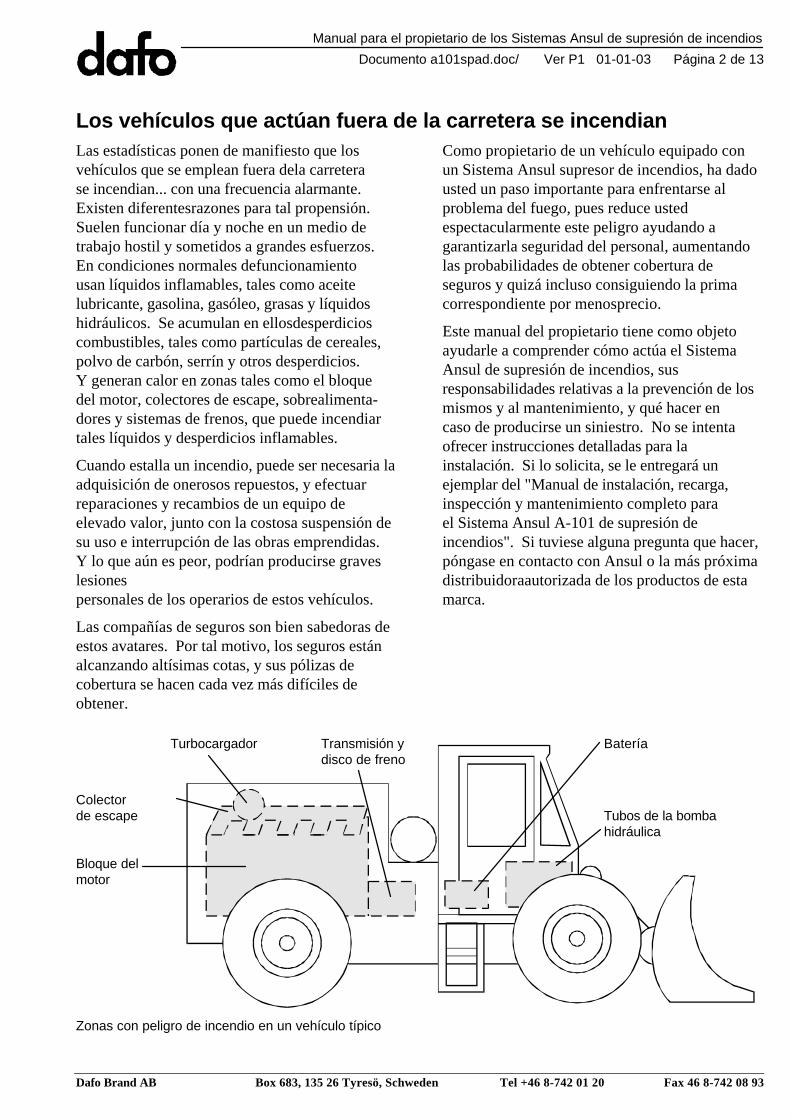
Los vehículos que actúan fuera de la carretera se incendianLas estadísticas ponen de manifiesto que losvehículos que se emplean fuera dela carreterase incendian... con una frecuencia alarmante.Existen diferentesrazones para tal propensión.Suelen funcionar día y noche en un medio detrabajo hostil y sometidos a grandes esfuerzos.En condiciones normales defuncionamientousan líquidos inflamables, tales como aceitelubricante, gasolina, gasóleo, grasas y líquidoshidráulicos. Se acumulan en ellosdesperdicioscombustibles, tales como partículas de cereales,polvo de carbón, serrín y otros desperdicios.Y generan calor en zonas tales como el bloquedel motor, colectores de escape, sobrealimenta-dores y sistemas de frenos, que puede incendiartales líquidos y desperdicios inflamables.
Cuando estalla un incendio, puede ser necesaria laadquisición de onerosos repuestos, y efectuarreparaciones y recambios de un equipo deelevado valor, junto con la costosa suspensión desu uso e interrupción de las obras emprendidas.Y lo que aún es peor, podrían producirse graveslesionespersonales de los operarios de estos vehículos.
Las compañías de seguros son bien sabedoras deestos avatares. Por tal motivo, los seguros estánalcanzando altísimas cotas, y sus pólizas decobertura se hacen cada vez más difíciles deobtener.
Como propietario de un vehículo equipado conun Sistema Ansul supresor de incendios, ha dadousted un paso importante para enfrentarse alproblema del fuego, pues reduce ustedespectacularmente este peligro ayudando agarantizarla seguridad del personal, aumentandolas probabilidades de obtener cobertura deseguros y quizá incluso consiguiendo la primacorrespondiente por menosprecio.
Este manual del propietario tiene como objetoayudarle a comprender cómo actúa el SistemaAnsul de supresión de incendios, susresponsabilidades relativas a la prevención de losmismos y al mantenimiento, y qué hacer encaso de producirse un siniestro. No se intentaofrecer instrucciones detalladas para lainstalación. Si lo solicita, se le entregará unejemplar del "Manual de instalación, recarga,inspección y mantenimiento completo parael Sistema Ansul A-101 de supresión deincendios". Si tuviese alguna pregunta que hacer,póngase en contacto con Ansul o la más próximadistribuidoraautorizada de los productos de estamarca.
Zonas con peligro de incendio en un vehículo típico
Turbocargador Transmisión y Bateríadisco de freno
Colectorde escape Tubos de la bomba
hidráulica
Bloque delmotor

Manual para el propietario de los Sistemas Ansul de supresión de incendios
Documento a101spad.doc/ Ver P1 01-01-03 Página 3 de 13
Dafo Brand AB Box 683, 135 26 Tyresö, Schweden Tel +46 8-742 01 20 Fax 46 8-742 08 93
Precauciones de seguridadEl sistema contra incendios que aquí se describese dedica únicamente a la supresión de losmismos, sin que esté creado ni concebido paraextinguir toda clase de incendios, especialmentecuando existan grandes cantidades de materialescombustibles en presencia de abundante oxígeno.
Es muy importante disponer de un equiposuplementario de lucha contra incendios en casode que el sistema por sí solo no pueda extinguir elfuego.Téngase mucho cuidado con que no seacumulen desperdicios y materiales y líquidoscombustibles que pudiesen generar un siniestrode mayores proporciones o contribuir a supropagación a zonas anteriormente carentes depeligrosidad al respecto.
Si se introdujesen modificaciones en el equipo asíprotegido o si el sistema de detección y/osupresión se desconectase por cualquier motivo,asegúrese de que un distribuidor de sistemascontra incendios para vehículos, autorizadopor Ansul, inspeccione y pruebe de inmediato elequipo.
Si no existiese sistema detector de incendios conaccionamiento automático, o estuviesedesconectado, no se producirían su disparo ydescarga a menos que se accionase manualmenteel sistema supresor. Por lo general, el dependerde un sistema manual de disparo resultará enmayor lentitud de reacción en presencia delsiniestro.
Su papel ante la protección de su vehículo contra el fuegoSu Sistema Ansul de supresión de incendios estácreado a la medida de lo que se quiere proteger enzonas peligrosas concretas del vehículo. Se haconcebido con todo cuidado para su fiabilidad yse ha construido siguiendo las más estrictasnormas de la calidad. Todo componente estáprobado para larga duración y uncomportamiento del que se pueda depender.
Con un mantenimiento adecuado, el SistemaAnsul de supresión de incendios leproporcionará años enteros de protección.
No obstante, el principal fin de este manual esexplicar la manera más sencilla de la proteccióncontra incendios... que es su prevención. Esbozalos pasos a seguir para impedir tales desastres.Las precauciones que se tomen pueden reducirmucho el riesgo de que se produzcan dañosgraves en caso de incendio. La prevención delfuego en los vehículos se apoya en dos factoresfundamentales:1. Inspección y mantenimiento preventivos en
los puntos donde es más probable que puedaprovocarse un incendio: bloque del motor,sistema eléctrico, turbocargadores, colectoresde escape y sistemas de frenos.
2. Limpieza regular de todas las zonas en que sepuedan depositar sustancias inflamables talescomo combustible, aceite, grasa, líquidohidráulico y residuos combustibles.

Manual para el propietario de los Sistemas Ansul de supresión de incendios
Documento a101spad.doc/ Ver P1 01-01-03 Página 4 de 13
Dafo Brand AB Box 683, 135 26 Tyresö, Schweden Tel +46 8-742 01 20 Fax 46 8-742 08 93
Mantenimiento preventivo contra incendios en vehículosA continuación se explica el mantenimiento diarioque se sugiere para reducir el riesgo de incendioen su vehículo.
PRECAUCIÓN:Tenga cuidado durante el mantenimiento,limpieza y soldadura. Para evitar que el sistemase dispare con la consiguiente expulsión delagente extintor, el tendido de detección delsistema no debe presentar cortes niestrangulamientos, ni someterse a un calorsuperior a 93°C (200
oF).
1. Inspeccione todas las tuberías de aceite, gasy líquido hidráulico por si presentasen cortes,abrasiones o excesivo desgaste. Efectúe losrecambios necesarios.
2. Inspeccione todos los empalmes de las tuberíasde aceite, gas y líquido hidráulico para ver si estánbien apretados. Limpie todos los derramesy apriételos bien.
3. Inspeccione y limpie la zona del motor. Según laclase de funcionamiento del vehículo, emplee aguao vapor para limpiarlo. Programe la limpieza parael final del turno de trabajo, momento en que puedahaber podido acumularse calor tras apagar el motor.
4. Compruebe el sistema de frenos para ver si ajustabien, especialmente cuando los frenos serecalienten aunque no actúen.
5. Compruebe todos los puntos posibles en que sepueda producir una ignición (bloque del motor,colectores de escape, turbocargadores, etc.).Cerciórese de que los conductos de líquidohidráulico o gas no estén en contacto con talespuntos.
6. Limpie todos los residuos combustibles: materiasvegetales, partículas de cereales, polvo de carbón,etc. Además, limpie todo aceite y combustible quehaya goteado.
7. Inspeccione todos las conexiones y cables eléctricospara comprobar si están flojos o presentan desgasteo abrasión. Recambie todo equipo eléctrico ocableado defectuoso.

Manual para el propietario de los Sistemas Ansul de supresión de incendios
Documento a101spad.doc/ Ver P1 01-01-03 Página 5 de 13
Dafo Brand AB Box 683, 135 26 Tyresö, Schweden Tel +46 8-742 01 20 Fax 46 8-742 08 93
Cómo funciona el sistema Ansul de supresión de incendios...manualmente
1. El fuego estalla en una zona protegida.
2. El operador del equipo tira de la anilla ygolpea el émbolo de los accionadoresmanuales. La presión del accionadorproduce el accionamiento del SistemaAnsul de supresión de incendios.
3. La presión de gas expulsor "licua" elextintor químico seco y lo impulsa através de la manguera de distribución.
4. El extintor químico seco se descargaa través de boquillas fijas en las zonasprotegidas, suprimiendo el incendio.
Y dispondrá de protección automática durante 24 horas al día con losSistemasde Detección y Accionamiento Ansul CHECKFIRE...

Manual para el propietario de los Sistemas Ansul de supresión de incendios
Documento a101spad.doc/ Ver P1 01-01-03 Página 6 de 13
Dafo Brand AB Box 683, 135 26 Tyresö, Schweden Tel +46 8-742 01 20 Fax 46 8-742 08 93
Cómo funciona el sistema con los dispositivos optativos deDetección y Accionamiento Eléctricos CHECKFIRE
1. El fuego estalla en una zona protegida.
2. Los detectores lineales o localizados señalan almódulo de control del sistema indicando que seha producido un incendio en tal zona protegida.
3. El módulo de control acciona el sistemade supresión de incendios. Este módulotambién suministra funciones de retraso yapague, así como de activación decomponentes auxiliares del vehículodependiendo de su instalación.
4. La presión del gas expulsor "licua" el agentequímico extintor y lo impulsa a través dela manga de distribución.
5. El agente químico extintor se descargaa través de boquillas fijas en las zonasprotegidas, para suprimir el incendio.

Manual para el propietario de los Sistemas Ansul de supresión de incendios
Documento a101spad.doc/ Ver P1 01-01-03 Página 7 de 13
Dafo Brand AB Box 683, 135 26 Tyresö, Schweden Tel +46 8-742 01 20 Fax 46 8-742 08 93
... o con los dispositivos optativos de Detección y AccionamientoNeumático CHECKFIRE
1. El fuego estalla en una zona protegida.
2. Las tuberías de detección del Sistema deDetección y Accionamiento NeumáticoCHECKFIRE se escinden a la temperaturade 179°C, descargando la presión del sistema.
3. El descenso de presión en el Dispositivo deDetección y Accionamiento (DDA) accionael sistema de supresión de incendios.
4. La presión del gas expulsor "licua" elagente químico extintor y lo impulsaa través de la manga de distribución.
5. El agente químico extintor se descargaa través de boquillas fijas en las zonasprotegidas, para suprimir el incendio.

Manual para el propietario de los Sistemas Ansul de supresión de incendios
Documento a101spad.doc/ Ver P1 01-01-03 Página 8 de 13
Dafo Brand AB Box 683, 135 26 Tyresö, Schweden Tel +46 8-742 01 20 Fax 46 8-742 08 93
Cerciórese de que el Sistema Ansul de supresión de incendios semantiene en buenas condiciones de funcionamientoEl Sistema Ansul de supresión de incendios es su segunda línea de defensa en caso de que no seansuficientes los esfuerzos preventivos. No obstante, para que funcione bien necesitará someterse ainspección y mantenimiento periódicos.
Boquillas Sistema de tuberías hidráulicas
Tapones Boquillas libres Boquillas Todos los Sin Tubo sineyectables y limpias de residuos bien sujetas ajustes muescas estrangulamientosen su sitio en sus soportes bien apretados(si los lleva)
Todas las grapas Sindel tubo bien soldadas rozaduraso atornilladas
Extintor manual portátil Depósito de agente extintor
Precintos Con la etiqueta del certificadovisibles en su del distribuidorsitio autorizado
Sin desgaste Sin desgasteexcesivo excesivo
Etiqueta con el certificadodel distribuidor
Sin corrosión
Firmemente sujetoSin corrosión
Inspección neumática CHECKFIRE Tubería de detección
Todas las abrazaderas Tubo sinAjustes apretados de nilón bien apretadas estrangulamientos
Sin muescas
La aguja del manómetromás allá del sector rojo
Todas las grapas Sin rozadurasdel tubo biensoldadas o atornilladas
Cableado sujeto
La luz no está encendida
Soporte bien soldadoo atornillado

Manual para el propietario de los Sistemas Ansul de supresión de incendios
Documento a101spad.doc/ Ver P1 01-01-03 Página 9 de 13
Dafo Brand AB Box 683, 135 26 Tyresö, Schweden Tel +46 8-742 01 20 Fax 46 8-742 08 93
Inspección eléctrica CHECKFIRE, Serie 1
Inspección eléctrica Cable de detección, cable de electricidadCHECKFIRE, Serie I
Pasador de anilla La luz debe encenderse Todas las abrazaderas de nilónen su sitio al apretar el pulsador Sin bien apretadasy precintado Bornes - muescas
de la bateríafirmes
Sinestrangulamientos
Todas las camisas de Singoma en su sitio rozaduras
Cargador Fusibleprecintado Conexiones en suinstalado firmes portafusible
Soporte bien soldadoo atornillado
Tubería de detección y/o detectorbien sujetos y sin averías
Inspección MP CHECKFIRE
Cargadorprecintadoinstalado
Soporte Inspeccione elPasador bien soldado sistema diariamentede anilla o atornillado a simple vistapuesto comprobando si ely precintado piloto VERDE de la
batería parpadea -Soporte una vez cada tresbien soldado segundos, sin queo atornillado parpadee ningún
otro pilotoCargadorprecintado instalado
Tubo de detección y/odetectores firmes y sin averías
Inspección SC CHECKFIRE
Soportebien soldado Pasador de anillao atornillado puesto y precintado
Inspeccione el sistemadiariamente a simplevista, comprobando siel piloto VERDE de laparpadea una vez cada parpadee ningún otropiloto
Cargador precintadoinstalado
Tubo de detección y/odetector firmes y sin averías
Manual para el propietario de los Sistemas Ansul de supresión de incendios
Documento a101spad.doc/ Ver P1 01-01-03 Página 10 de 13
Dafo Brand AB Box 683, 135 26 Tyresö, Schweden Tel +46 8-742 01 20 Fax 46 8-742 08 93
A la hora de modificar el vehículo, planifíqueloSu Sistema Ansul de supresión de incendios se hacreado expresamente para instalarlo en suvehículo y proteger del fuego zonas concretas depeligro. Si posteriormente añadiese al vehículoequipo accesorio o introdujese en él importantesmodificaciones de tipo mecánico, podríadisminuir la capacidad extintora del sistema.
Si piensa introducir modificaciones de estanaturaleza, póngase en contacto con sudistribuidor de Ansul. Éste podrá evaluar denuevo el sistema para proporcionarle la seguridadde que queden protegidas de las llamas todas laszonas de peligro.
Planifique un mantenimiento periódicoEl mantenimiento periódico es esencial para quefuncione el Sistema Ansul de supresión deincendios a pleno rendimiento. Diríjase a sudistribuidor de productos Ansul para efectuar afondo el seguimiento, inspección ymantenimiento periódicos.
Protección contra incendios fuera de la zona de peligroLos extintores de incendios portátiles son unmedio eficaz de apagar los incendios que puedanproducirse fuera del vehículo o zonas noprotegidas por el Sistema Ansul de supresión deincendios. Su distribuidor de productos Ansulpodrá recomendarle el tamaño, tipo y colocaciónidóneos de los extintores portátiles, así comoimpartir al personal la formación correspondientea efectos de funcionamiento, inspección ymantenimiento.
Si estallase un incendio en una zona no protegidapor el Sistema Ansul de supresión de incendios,el extintor manual portátil podrá utilizarse comosigue:
1. Apague el motor del vehículo y eche losfrenos.
2. Proceda a evacuar el vehículo y tome unextintor manual portátil.
3. Acérquese al fuego por el lado contrario adonde sopla el viento.
4. Accione el extintor siguiendo las instruccionesimpresas en su placa de características.
5. Una vez apagado el fuego, quédese a laexpectativa por si volviera a prenderse denuevo.

Manual para el propietario de los Sistemas Ansul de supresión de incendios
Documento a101spad.doc/ Ver P1 01-01-03 Página 11 de 13
Dafo Brand AB Box 683, 135 26 Tyresö, Schweden Tel +46 8-742 01 20 Fax 46 8-742 08 93
En caso de estallar un incendio en su vehículoPara accionar manualmente el sistema:
1. Apague el motor
2. Eche los frenos
3. Tire del pasador de anilla del accionadormanual y golpee el pulsador rojo
4. Proceda a evacuar el vehículo
5. Prepárese a actuar con un extintor

Manual para el propietario de los Sistemas Ansul de supresión de incendios
Documento a101spad.doc/ Ver P1 01-01-03 Página 12 de 13
Dafo Brand AB Box 683, 135 26 Tyresö, Schweden Tel +46 8-742 01 20 Fax 46 8-742 08 93
Registro de inspección y mantenimientoFecha Distribuidor autorizado por Ansul Recarga Inspección Actuación seguida
Su distribuidor autorizado de productos de Ansul

Manual para el propietario de los Sistemas Ansul de supresión de incendios
Documento a101spad.doc/ Ver P1 01-01-03 Página 13 de 13
Dafo Brand AB Box 683, 135 26 Tyresö, Schweden Tel +46 8-742 01 20 Fax 46 8-742 08 93
ANSUL es marca registrada y CHECKFIRE es una marca comercial. Part no 418 383