component design - e-learning.kku.ac.th
TRANSCRIPT

CH APT E R 8 System Identification and Description and Component Design 195
There are also fluid mechanical systems to control braking, steering, and in otherhydraulic systems for special applications such as dump trucks.
Component DesignWe described several systems in the previous sections. We now start with the de-sign of components to demonstrate the application of the methodology detailedin Chapter 2 and the synthesis of the different disciplines in thermal sciences. Theapplication of the principles of design are demonstrated in the design of threecomponents in this chapter-a condenser, a space heater, and a wind tunnel.
8.7 CondenserCondensers are used in a large number of systems; a condenser is an essentialcomponent of steam power plants and refrigeration plants. Condensers are also usedin chemical plants and other situations.
Having identified a condenser for a component design, we design a condenserfor a small power plant. The condenser is to be designed for a steam turbine. Theinformation about the turbine is available in Table 8.1.
8.7.1 Develop Preliminary Specifications and Constraints
There are no explicit constraints. In the absence of any information, we assumethat the required amount of cooling water is available if we choose a water-cooledcondenser. We will require that the condenser should
• Be easy to maintain and repair• Conform to applicable practices• Be such that the temperature rise of the cooling water should not exceed about
7 DCto conform to current practice.
8.7.2 Develop Detailed Specifications and Concept
1. Assume feedwater leaves the condenser at a temperature slightly below thetemperature corresponding to the saturation temperature at the exit pressure of10 kPa.
Table 8.1 Steam turbine
Turbine outputSteam pressure at inlet to turbineSteam temperature at inletExit pressureEfficiency of turbineTemperature of available cooling waterTemperature of ambient air
1000 kW2000 kPa400 QC
10 kPa0.825°C40 °C

196 PART 3 System Identification and Description, Component and System Design, and Simulation
Table 8.2 Comparative merits of water-cooled and air-cooled condensers
CostWeightVolumeNoiseSource-air or waterRepairReliability +
++++
Available++
Available
2. The two types of condensers to be considered are the water-cooled condenserand the air-cooled condenser. Water-cooled condensers are generally of theshell-and-tube type, either one-tube pass or two-tube pass. Air-cooledcondensers are generally of the cross-flow type with plates attached to thetubes acting as extended surfaces.
3. The current practice is to limit the water velocity in tubes to a maximum ofabout 2.5 mls and air velocity for air-cooled condensers to about 10 mls.
Consider the two possible designs. Evaluate the advantages and disadvantagesof each type, as in Table 8.2. Instead of a numerical rating, indicate the type that ismore desirable with a + and the less desirable one with a -. Then look at the overallpicture to define the more desirable type of condenser. Considering the relative mer-its, a water-cooled condenser is the desirable choice. However, if a suitable source ofwater is not available, an air-cooled condenser would be chosen.
Two types of shell-and-tube condensers are the single-tube pass and the two-tube pass. In the single-pass condenser water enters the condenser at one end andleaves it at the other end; in the two-tube pass type, water enters the condenser at oneend, but exits at the same end; i.e., the water flows from one end to the other twice.The two-tube pass condenser is slightly more complicated, as both the water inletand exit are at the same end. But it is easier to maintain and repair. It is likely to leadto a smaller length. Choose the two-tube pass condenser (Figure 8.6).
8.7.3 Detailed Design
Further specifications are as follows:
• The condenser may be either rectangular or circular (including oval). Thechoice is somewhat arbitrary. Choose a rectangular condenser.
• Length should be between 1 to 3 times the width.• As already indicated, water velocity is limited to a maximum of 2.5 m/so
Preferred velocity is 2 mls.
Steps involved in the design are:
1. Estimate the heat transfer rate.2. Determine the cooling water flow rate.3. For different velocities of the cooling water and diameter of tubes, find the
length of the tubes.

CH APT E R 8 System Identification and Description and Component Design 197
CD
¥V = 1000 kW
Turbine
mw~--~----~~~8Coolingwater
'--------1----====::::;.;::- 0
Figure 8.6 Schematic of turbine-condenser
4. Compute the pumping power in each case.5. Choose the most desirable combination of the sizes of the condenser and
pumping power.
Refer to Figure 8.6.
1. Estimate the Heat Transfer Rate With the normal nomenclature,
(8.1)
where q is the heat transfer rate from the steam to the cooling water, rilst is computedfrom the following set of equations.
2. Determine the Cooling Water Flow Rate Assuming a reasonable value of T3,
between the exit temperature 1~of the cooling water and the saturation temperature 12,the heat transfer rate is found.
The mass rate of flow of the cooling water is obtained from the relation:
Assuming a reasonable cooling water exit temperature (not to exceed 7 QCabovethe inlet temperature) the cooling water mass flow rate is determined.

198 PART 3 System Identification and Description, Component and System Design, and Simulation
3. For Different Velocities of the Cooling Water and Diameter of Tubes, Findthe Length of the Tubes The condenser design is defined by the diameter, length,and number of tubes in the condenser, the arrangement (in-line or staggered) andspacing of the tubes, and water velocity. There are a number of combinations ofthe design that will satisfy the heat transfer requirement. A parametric study will beperformed so that one or more appropriate designs can be identified. The steps in thedesign are:
1. Assume a tube diameter.2. Assume a water velocity between, say, 1.5 mls and 2.5 mls.3. Determine the number of tubes in each pass to yield the required mass rate of
flow of water.4. Determine the water-side convective heat transfer coefficient, hi.
5. Determine the steam-side convective heat transfer coefficient, ho. Thecondensation heat transfer coefficient requires the tube surface temperature,which is not known. It is determined by iteration.
6. Determine the overall heat transfer coefficient, U.
7. Determine the surface area, and length of the tubes from Equation 6.130(replacing TH by Tsat)
(Tsat - Te) UA Un dL2N
In Tsat - T; = - mwcpw = - rhwcpw
where L is the length of the tubes (in each pass), N is the number of tubes per pass,and 2N is the total number of tubes in the condenser.
One set of calculations follows. The results for the other sets are given inTable 8.5. The EES program (Appendix B) is used to find all the property values andto perform the computations.
Determine the heat transfer rate:
i1(200 kPa,400°C) = 3247.2kJlkg
SI (200 kPa, 400°C) = S2s = 7.126kJlkg· K
X2s = 0.8637
i2s = 2258.8 kJ/kg
i} - i: 3247.2 - izttt = _ ..- :::}0.8 = :::}i2 = 2456.5 kJ/kgi1 - izs 3247.2 - 2258.8
Corresponding to iz = 2456.5 kJlkg and p = 10 kPa, p = 0.07204 kg/nr' andx (quality) = 0.9403.
mstCil - iz) = Hr:::} nlst(3247.2 - 2456.5) = 1000:::} nIst = 1.265kg/s
Note that the condensate temperature should be between Tsat and the averagecooling water bulk temperature. The maximum cooling water temperature rise is 7°C.
CH APT E R 8 System Identification and Description and Component Design 199
Assuming an actual temperature rise of 5 QC,with the cooling water inlet temperatureat 25 QCthe exit temperature is 30 QC.The exit condensate is between Tsat = 45.85 QCand the average cooling water temperature of27.5 QC.Therefore, to find the heat trans-ferrate to the cooling water assume that the temperature of the condensate is 40 QC.Ifthe actual temperature of the condensate is slightly different from the assumed tem-perature, the computed heat transfer rate changes only by a small amount as the majorpart of the heat transfer is due to condensation and the effect of subcooling on the heattransfer rate is small. Thus, with T3 = 40 QC,i3 = 167.4 kJ/kg.
q = mst(i2 - i3) = 1.265(2456.5 - 167.4) = 2895 kW
The specific heat of the cooling water at the mean temperature of 27.5 QC is4.176 kJ/kg . K. The mass rate of cooling water is then given by
mwcpw(Te -~) = q =} ritw x 4.176(30 - 25) = 2895 =} mw = 138.7kg/s
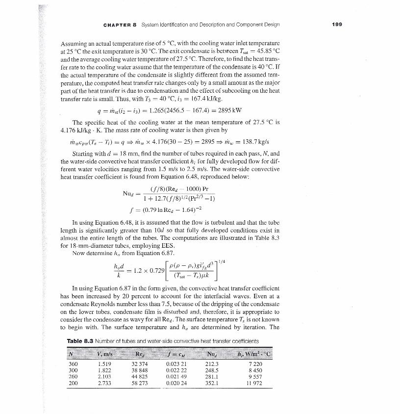
Starting with d = 18 mm, find the number of tubes required in each pass, N, andthe water-side convective heat transfer coefficient hi for fully developed flow for dif-ferent water velocities ranging from 1.5 rnIs to 2.5 rnIs. The water-side convectiveheat transfer coefficient is found from Equation 6.48, reproduced below:
Nu = _(-,-f-,-/8--,-)_(R_e_d_-_lO_0~0~)_Pr_d 1 + 12.7(f/8)1/2(P~/3 -1)
f = (0.79 In Red - l.64)-2
In using Equation 6.48, it is assumed that the flow is turbulent and that the tubelength is significantly greater than lOd so that fully developed conditions exist inalmost the entire length of the tubes. The computations are illustrated in Table 8.3for 18-mm-diameter tubes, employing EES.
Now determine h; from Equation 6.87.
[
( )'/ d3]1/4hod = 1.2 x 0.729 P P - Pv glfg
k (Tsat - Ts)f.Lk
In using Equation 6.87 in the form given, the convective heat transfer coefficienthas been increased by 20 percent to account for the interfacial waves. Even at acondensate Reynolds number less than 7.5, because of the dripping of the condensateon the lower tubes, condensate film is disturbed and, therefore, it is appropriate toconsider the condensate as wavy for all Red. The surface temperature T, is not knownto begin with. The surface temperature and ho are determined by iteration. The
Table 8.3 Number of tubes and water-side convective heat transfer coefficients
1.5191.8222.1032.733
32374388484482558273
0.023210.022220.021490.02024
212.3248.5281.1352.1
722084509557
11972
200 PART 3 System Identification and Description, Component and System Design, and Simulation
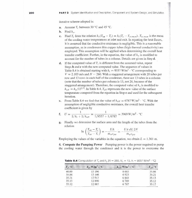
iterative scheme adopted is:
a. Assume T, between 30 QCand 45 QC.
Find ha.
Find T, from the relation ho(Tsal - Ts) = hi (Ts - Tw,mean)· Tw,mean is the meanof the cooling water temperatures at inlet and exit. In equating the heat fluxes,it is assumed that the conductive resistance is negligible. This is a reasonableassumption, as in condensers thin copper tubes (high thermal conductivity) areemployed. This assumption will be applied when determining the overall heattransfer coefficient. Further, in the equation, the value of ha is modified toaccount for the number of tubes in a column. Details are given in Step d.If the computed value of T, is different from the assumed value, repeatSteps band c with the new computed value. The sequence of values inTable 8.4 is obtained starting with hi = 9557 W/m2 . QCcorresponding toV = 2.103 m/s and N = 260. With a staggered arrangement with 20 tubes perrow and 13 rows in each half of the condenser, there are 13 tubes in a column(note that the number of tubes per column is 13, not 26, because of thestaggered arrangement). Therefore, the computed value of ha is modified tohON = ho/131/4. In Table 8.4, TSN represents the new value of the surfacetemperature computed from the equation in Step c and used for the subsequentiteration.From Table 8.4 we find that the value of n;» = 6787 W1m2. cc. With theassumption of negligible conductive resistance, the overall heat transfercoefficient is given by
1U- .-- Ilhi + I/hoN -
b.c.
d.
e.
f. 1 = 3969 W m2. QC1/9557 + 1/6787 1
g. Finally we determine the surface area and the length of the tubes from therelation
(Tsal - Te) UA· UT[ dL 2N
In Tsat - T, = - n1.wcpw = - li1wCpw
Employing the values of the variables in the equation, we obtain L = 1.361 m.
4. Compute the Pumping Power Pumping power is the power required to pumpthe cooling water through the condenser and it is the power to overcome the
Table 8.4 Computation of Ts and n: (N = 260, Ne = 13, hi = 9557 W/m2 . QC)
Ts'OC h W/m2. °C '!-O;" W/m2• °C TsN'oC0' .
40.00 15 196 8003 35.8635.86 13 146 6923 35.2135.21 12917 6803 35.l335.13 12890 6789 35.1235.12 12887 6787 35.12
CHAPTER 8 System Identification and Description and Component Design 201
frictional pressure drop. Denoting the pressures of the cooling water at inlet and exitby Pi and p, respectively, the pumping power (Equation 5.41) is given by:
. mwWrev = - (Pi - Pe)
p
For the present case, the pressure difference is a combination of the pressuredrop in the tubes and in the water boxes. Neglecting changes in kinetic and potentialenergies, the pressure drop in the tubes (Equation 5.34) is given by:
V2Lhf = CM-- Pi - Pe = hfpg CM = (0.79 In Red - 1.64)-2
2g d
The value of CM = 0.02149. For the friction head in the pipe of a total length of2.722 m (twice the length of the pipe from one end to the other) with a velocity of2.103 m/s and density of 997.1 kg/rrr', we have
2.103 x 2.103 x 2.722hf = 0.021 49 x 2 x 9.807 x 0.018 = 0.733 m
To this we add an estimated 1m to account for the losses in the water boxes, valves,and screens at inlet (to prevent debris) so that the total head loss h.ft is 1.733 m. Theresult is:
Wrev = hft x g x mw = 1.733 x 9.807 x 138.7 = 2357 W
Assuming a pump efficiency of 0.8, the pumping power is
Wp = Wrev/1]p = 2946W
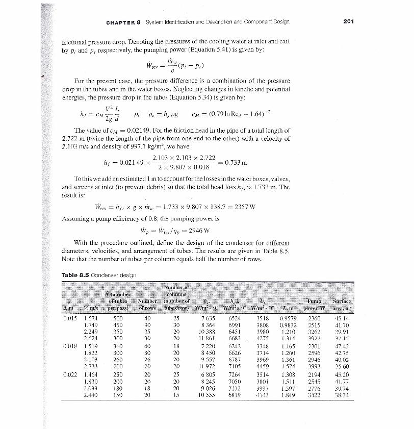
With the procedure outlined, define the design of the condenser for differentdiameters, velocities, and arrangement of tubes. The results are given in Table 8.5.Note that the number of tubes per column equals half the number of rows.
Table 8.5 Condenser design
0.015 1.574 500 40 25 7635 6524 3518 0.9579 2360 45.141.749 450 30 30 8364 699.1 3808 0.9832 2515 41.702.249 350 35 20 10388 6451 3980 1.210 3262 39.912.624 300 30 20 11 861 6683 4275 l.314 3927 37.15
0.018 1.519 360 40 18 7220 6242 3348 1165 2301 47.431.822 300 30 20 8450 6626 3714 1.260 2596 42.752.103 260 26 20 9557 6787 3969 1.361 2946 40.022.733 200 20 20 11 972 7105 4459 1.574 3993 35.60
0.022 1.464 250 20 25 6805 7264 3514 1.308 2194 45.201.830 200 20 20 8245 7050 3801 1.511 2545 41.772.033 180 18 20 9026 7172 3997 1.597 2776 39.742.440 150 20 15 10 555 6819 4143 1.849 3422 38.34

202 PART 3 System Identification and Description, Component and System Design. and Simulation
An interesting feature of the design is that with three different diameters and fourdifferent water velocities, the surface areas of the different designs are surprisinglyclose, except for the lowest velocities. We may decide on the design, depending on Ourcriteria for the final configuration. If the surface area, which also indicates the totalmass (assuming the same thickness of tubes) is required to be a minimum, the best de-sign would be with IS-mm diameter and a water velocity of2.624 m/s. However, withthat design the pumping power is also very high. Considering pumping power andsurface area, possible choices are with a water velocity of about 1.8 m/s. With 22-m111-diameter tubes, the number of tubes is the lowest with 200 tubes per pass. As the num-ber of tubes is directly related to manufacturing costs, we choose that design. It shouldbe noted that the condenser should include water boxes at either end (Figure 6.26) anda suitable plate at the top to prevent the impingement of the high-speed exhaust steam(with water droplets) on the tubes. These will make the overall dimensions signifi-cantly higher than the tube bank dimensions.
Diameter of Tube at Inlet to the Condenser The diameter of the tube depends onthe velocity of the steam at inlet. A steam inlet velocity of 30 to 60 m/s is suggestedin Fraas (1989). With steam at 10 kPa and a quality of 0.9403, the density of thesteam is 0.07204 kg/rrr'. For a steam velocity of 40 m/s, the diameter of the tube atinlet of the condenser is
tt X d2 X P X Vmst = ------~----
4Jr X d2 x 0.072 04 x 40
1.265 = 4
d = 74.8 cm ~ 75 cm
Diameter of Cooling Water Pipes at Inlet to the Condenser The density of waterat 25 QC, 100 kPa is 997.9 kg/rrr'. Velocity of water is generally around 2 m/s for suchapplications. Assuming a velocity of 2 m/s, for a mass flow rate of water of 138.7kg/s, the cooling water tube diameter is
Jr X d2X P X V
mw = 4Jr X d2 x 997.9 x 2
138.7 = 4
d = 29.75 cm ~ 30cm
The final design is given in Table 8.6.
Table 8.6 Design of condenser
Diameter of tubesLength of tubesNumber of tubes per passSurface area (total)Cooling water velocity in
condenser tubesPumping powerTube arrangementNumber of rows
22 mm1.51 m20041.77 m21.83 m/s
2088 mm88 mm1.94 m1.94 m75 cm30 cm
Number of columnsPitch between rowsPitch between columnsWidth of tube banksHeight of tube banksDiameter of steam tubeDiameter of cooling water
pipes to condenser2545WStaggered20

CHAPTER 8 System Identification and Description and Component Design 203
In the final design we find that the ratio ofthe length to the width of the tube banksis 0.78. In the further specifications in Section 8.7.3, the suggested length-to-widthratio is between 1 and 3. However, adding a water box on either side of the tube banksin the suggested design increases the condenser length, bringing the ratio closer to 1.
8.8 Electric Space HeaterIn many residential buildings, during winters the heating of some of the rooms maynot be adequate for comfort. Because of unbalance in the supply of the heatingmedium (heated air or water), a room may not attain the desired temperature, or somepersons may feel more comfortable at a higher room temperature. In such cases,additional heating is provided by an auxiliary, stand-alone unit. One popular type ofsuch a unit is an electric space heater.
8.8.1 Preliminary Specifications
An electric space heater is to be designed to raise the temperature of a large room by10 "C. The temperature of the room is to be controlled by a manually set thermostat.The space heater must be functional and satisfy safety features that will allow it to besuccessfully marketed and sold to the general public. It is to be designed to supple-ment the existing central heating system.
8.8.2 Develop More Detailed Specifications
A typical house would have several rooms, not all of the same size, with partitionsand doors in between. Maximum heating load would be for a room with maximumexposure to outside air with a reasonable number of windows of conventional sizes.The list below reflects these ideas and will be used as the basis for selecting the heat-ing load.
• Space to be heated is a room measuring 6 m x 6 m x 2.5 m (20ft x 20 ft x 8 ft).• Room has two interior and two exterior walls. Each exterior wall is fitted with
a 1.5 m x 1.5 m (5 ft x 5 ft) double pane window. One of the interior wallshas a 0.9 m x 2.1 m x 0.05 m (3 ft x 7 ft x 2 in) hardwood door of normalconstruction.
• The room has a basement below and a second floor above.• Exterior walls consist of a dry wall (12.7 mm), fiberglass insulation (90 mm),
studs (38 mm x 90 mm), plywood (12.7 mm), foam insulating sheathing(13 mm), and wood bevel lapped siding (13 mm x 200 mm). The ceiling andthe floor are of traditional construction, consisting of drywall, studs, andhardwood floor.
• All the studs are placed 400 mm (~16 in) apart (on center).
8.8.3 Develop Concepts
The information in this project is based on two major sources: Kreider and Rabl(1994), and ASHRAE (2001) SI edition.