compliant multi-link vehicle suspensions systems dynamics and control/papers...compliant multi-link...
TRANSCRIPT

Clemson UniversityTigerPrints
All Theses Theses
7-17-2008
Compliant Multi-Link Vehicle SuspensionsSouharda RaghavendraClemson University, [email protected]
Follow this and additional works at: http://tigerprints.clemson.edu/all_thesesPart of the Engineering Mechanics Commons
Please take our one minute survey!
This Thesis is brought to you for free and open access by the Theses at TigerPrints. It has been accepted for inclusion in All Theses by an authorizedadministrator of TigerPrints. For more information, please contact [email protected].
Recommended CitationRaghavendra, Souharda, "Compliant Multi-Link Vehicle Suspensions" (2008). All Theses. Paper 405.

COMPLIANT MULTI-LINK VEHICLE SUSPENSIONS
A Thesis
Presented to
the Graduate School of
Clemson University
In Partial Fulfillment
of the Requirements for the Degree
Master of Science
Mechanical Engineering
by
Souharda Raghavendra
August 2008
Accepted by:
Dr. Beshah Ayalew, Committee Chair
Dr. John C. Ziegert
Dr. Mohammed Daqaq

ii
ABSTRACT
One of the goals of automotive lightweight engineering is to achieve reduction in
mass, cost, and complexity of vehicle components, subsystems and systems without
sacrificing functionality and expected performance. This thesis addresses functionally
integrated suspension systems that could lead to reduction in part count and mass and
save packaging space. It deals with the analysis of multi-link suspensions that combine
the function of energy storage and the mechanism of wheel location and guidance within
individual compliant links and members.
To explore possibilities, a generic kinematic model of an independent five-link
suspension was built in the MSC.ADAMS multi-body dynamics simulation environment.
Models of the compliant energy storage and kinematic guidance members were created
using a finite element analysis package and interfaced with the MSC.ADAMS
environment. Then, the main spring, and individual and multiple rigid links of the
reference suspension were replaced with compliant members, and subsequently, the
resulting kinematic characteristics of the compliant multi-link suspension were compared
against those of the reference rigid multi-link suspension. Under certain achievable
assumptions and a suitable choice of the dimensions of the compliant links, it was found
that similar kinematic characteristics as the reference suspension could be achieved by
variants of the compliant multi-link suspension consisting of compliant links.
The analysis was also applied to the development of a compliant suspension
concept for an existing high performance vehicle. Model validation data were obtained
from actual tests conducted on a kinematic and compliance test rig. Evaluation of

iii
possible compliant variants of the rear suspension for this vehicle led to the replacement
of the upper control arm of the original suspension with a ternary-link compliant member.
The kinematic and compliance characteristics of this modified suspension were
thoroughly analyzed through simulations and some of the characteristics were validated
with tests conducted using a test-fixture employing many parts of the actual suspension
and an aftermarket composite member for the compliant ternary-link.
The compliant suspension concepts evaluated in both phases use fewer parts, and
therefore exhibit reduced mass and complexity. Further research and development is
required to comprehensively optimize the design of the compliant links for certain
desired response attributes, such as better toe control.

iv
DEDICATION
This thesis is dedicated to my parents, Mr. Raghavendra Ramaiah Muniyappa,
Mrs. Dakshayini Raghavendra and my elder brother, Mr. Santhosh Raghavendra without
whose unconditional love support this thesis would not be complete.
v
ACKNOWLEDGMENTS
I would like to express my sincere gratitude to my advisors, Dr. Beshah Ayalew
and Dr. John C. Ziegert, for their priceless guidance, and constant support for the
completion of this thesis and funding me throughout my graduate study. I extend my
sincere thanks to Dr. Mohammed Daqaq for being a part of my committee and for his
valuable suggestions. I would also like to thank Mr. Norbert Seyr and Mr. Andreas
Obieglo of BMW for their valuable suggestions and contributions.
Furthermore I would like to specially thank Mr. Vincent Lee for his continuous
and selfless help during the course of this work. I warmly thank my roommate Mr.
Guruprasad Arakere and fellow graduate student Mr. Santosh Tiwari for their valuable
advice and friendly help. Their extensive discussions have been very helpful for this
thesis.
Finally I would like to thank my family, my colleagues at office and all my
friends for the love and care throughout the course of this work.

vi
TABLE OF CONTENTS
Page
TITLE PAGE .................................................................................................................... i
ABSTRACT ..................................................................................................................... ii
DEDICATION ................................................................................................................ iv
ACKNOWLEDGMENTS ............................................................................................... v
LIST OF TABLES ........................................................................................................ viii
LIST OF FIGURES ........................................................................................................ ix
CHAPTER
1. INTRODUCTION ............................................................................................... 1
1.1 Thesis objective ................................................................................. 3
1.2 Thesis outline ..................................................................................... 3
2. BACKGROUND AND LITERATURE REVIEW ............................................. 5
2.1 Suspension systems ............................................................................ 5
2.2 General compliant mechanisms ......................................................... 7
2.3 Suspension concepts with compliant members................................ 11
2.4 Suspension characteristics ............................................................... 21
3. COMPLIANT MUTLI-LINK SUSPENISON CONCEPTS ............................. 25
3.1 Reference multi-link suspension model ........................................... 25
3.2 Compliant suspension model ........................................................... 32
3.3 Compliant suspension results ........................................................... 37
3.4 Chapter summary ............................................................................. 46
4. COMPLIANT SUSPENSION CONCEPTS FOR A
REFERENCE VEHICLE....................................................................... 48
4.1 Introduction ...................................................................................... 48

vii
Table of Contents (Continued)
Page
4.2 Description of the reference suspension model ............................... 48
4.3 Development of compliant suspension ............................................ 49
4.4 Chapter summary ............................................................................. 70
5. CONCLUSIONS AND FUTURE WORK ........................................................ 72
5.1 Conclusions ...................................................................................... 72
4.4 Future work ...................................................................................... 74
APPENDIX .................................................................................................................... 76
REFERENCES .............................................................................................................. 87

viii
LIST OF TABLES
Table Page
1 Coordinates of multi-link suspension with respect to
different coordinate systems .................................................................. 27
2 Coordinates of multi-link suspension with respect to
single coordinate systems ...................................................................... 29
3 Orthotropic properties of composite compliant member ............................. 34
4 Calculation of overall performance for each compliant
suspension concept................................................................................. 41

ix
LIST OF FIGURES
Figure Page
1 Traditional leaf spring used on early Mercedes 170 V .................................. 2
2 Examples of general compliant mechanisms ................................................. 9
3 Prosthetic leg as a compliant mechanism ...................................................... 9
4 Commercially available compliant mechanisms ......................................... 10
5 Compliant mechanism used in MEMS ........................................................ 11
6 Longitudinal leaf spring used in Jeep .......................................................... 12
7 Different configurations of longitudinal and transverse
leaf springs ............................................................................................. 13
8 Examples of known compliant suspension similar to the
configuration shown - I .......................................................................... 13
9 Examples of known compliant suspension similar to the
configuration shown -II.......................................................................... 14
10 Examples of transverse leaf springs used in Corvette and
Escort production vehicle ...................................................................... 14
11 Examples of longitudinal leaf spring used in hybrid truck
and Bugatti ............................................................................................. 15
12 Double A-arm suspension ............................................................................ 15
13 Double A arm suspension using flexural pivots in F1
race cars ................................................................................................. 16
14 McPherson strut and its compliant counterpart ........................................... 17
15 U-link original and modified configuration ................................................. 17

x
List of Figures (Continued)
Figure Page
16 Prototype of compliant U-link showing large bending
and low torsional deflection ................................................................... 18
17 U-link compliant suspension prototype ....................................................... 19
18 Torsional elevated compliant suspension .................................................... 20
19 Flexible link elevated compliant suspension ............................................... 20
20 Multi-link suspension architecture ............................................................... 26
21 Kinematic model of the rigid multi-link suspension.................................... 30
22 Non-linear force deflection curve for the spring used in
the reference multi-link suspension model ............................................ 31
23 Results of reference rigid multi-link suspension ......................................... 32
24 Composite transverse and longitudinal leaf springs,
replacing a coil spring ............................................................................ 33
25 Compliant multi-link suspension and its performance
characteristic with its 5th
link compliant ................................................ 43
26 Compliant multi-link suspension and its performance
characteristic with its 3rd
, 2nd
link compliant ........................................ 44
27 Compliant multi-link suspension and its performance
characteristic with its 5th
link compliant ................................................ 45
28 Schematic of the reference suspension ........................................................ 49
29 Sliding clip concept...................................................................................... 51
30 Binder clip concept ...................................................................................... 52
31 Cross leaf spring .......................................................................................... 53
32 Leaf spring and twist beam .......................................................................... 54

xi
List of Figures (Continued)
Figure Page
33 Ternary link and trailing arm ....................................................................... 55
34 Schematic of ternary link ............................................................................. 56
35 Reference suspension and its compliant suspension
concept ................................................................................................... 58
36 Compliant suspension concept at its ride height .......................................... 59
37 Compliant suspension concept at its rebound position ................................ 59
38 Compliant suspension concept at its bounce position.................................. 60
39 Camber change v/s vertical displacement .................................................... 62
40 Wheel loads v/s vertical deflection .............................................................. 63
41 Wheel loads v/s vertical deflection with change in
material property .................................................................................... 64
42 Lateral wheel loads v/s lateral wheel displacement ..................................... 65
43 Longitudinal wheel loads v/s Longitudinal wheel
displacement .......................................................................................... 66
44 Toe change v/s vertical displacement .......................................................... 67
45 Camber angle v/s vertical displacement for straight
compliant ternary link ............................................................................ 68
46 Toe angle v/s vertical displacement for straight
compliant ternary link ............................................................................ 68
47 Toe angle v/s vertical displacement for modified
chassis connection point ........................................................................ 70

xii
List of Figures (Continued)
Figure Page
48 Compliant multi-link suspension performance charactistics
with compliant 1st link ........................................................................... 76
49 Compliant multi-link suspension performance charactistics
with compliant 2nd
link........................................................................... 76
50 Compliant multi-link suspension performance charactistics
with compliant 3rd
link ........................................................................... 77
51 Compliant multi-link suspension performance charactistics
with compliant 4th
link ........................................................................... 77
52 Compliant multi-link suspension performance charactistics
with compliant 2nd
and 1st link ............................................................... 78
53 Compliant multi-link suspension performance charactistics
with compliant 3rd
and 1st link ............................................................... 78
54 Compliant multi-link suspension performance charactistics
with compliant 4th
and 1st link ................................................................ 79
55 Compliant multi-link suspension performance charactistics
with compliant 4th
and 2nd
link ............................................................... 79
56 Compliant multi-link suspension performance charactistics
with compliant 4th
and 3rd
link ............................................................... 80
57 Compliant multi-link suspension performance charactistics
with compliant 5th
and 1st link ................................................................ 80
58 Compliant multi-link suspension performance charactistics
with compliant 5th
and 2nd
link ............................................................... 81
59 Compliant multi-link suspension performance charactistics
with compliant 5th
and 3rd
link ............................................................... 81
60 Compliant multi-link suspension performance charactistics
with compliant 5th
and 4th
link ............................................................... 82

xiii
List of Figures (Continued)
Figure Page
61 Compliant multi-link suspension performance charactistics
with compliant 3rd
, 2nd
and 1st link ......................................................... 82
62 Compliant multi-link suspension performance charactistics
with compliant 4th
, 2nd
and 1st link ......................................................... 83
63 Compliant multi-link suspension performance charactistics
with compliant 4th
, 3rd
and 1st link ......................................................... 83
64 Compliant multi-link suspension performance charactistics
with compliant 4th
, 3rd
and 2nd
link ........................................................ 84
65 Compliant multi-link suspension performance charactistics
with compliant 5th
, 2nd
and 1st link ......................................................... 84
66 Compliant multi-link suspension performance charactistics
with compliant 5th
, 2nd
and 1st link ......................................................... 85
67 Compliant multi-link suspension performance charactistics
with compliant 5th
, 2nd
and 1st link ......................................................... 85
68 Compliant multi-link suspension performance charactistics
with compliant 5th
, 2nd
and 1st link ......................................................... 86
69 Compliant multi-link suspension performance charactistics
with compliant 5th
, 2nd
and 1st link ......................................................... 86

1
CHAPTER 1
INTRODUCTION
Vehicle suspensions can be collectively described as an arrangement of kinematic
linkages and force elements (springs, dampers and bushings) connecting the chassis and
the wheels to ensure constant contact of the wheels with the road. The functions of
kinematic links, springs and dampers is, respectively, to provide wheel location, energy
storage and energy dissipation and to isolate the vibrations excited by road irregularities
and thereby enhance driving pleasure. In doing so, suspensions have a direct effect on the
ride and handling comfort of the vehicle.
The motive behind this thesis is to research the possibility of effectively
integrating energy storage and wheel guidance capabilities of the suspension system
using compliant links that replace the original rigid kinematic links within the
suspension, with little or no compromise in system performance. This integration has
advantages such as reduction in weight, part count, and cost, and thereby offers enhanced
reliability compared to traditional suspension systems. The latter occupy as much as 12 %
of the overall mass of the vehicle (1).
The thesis draws ideas from the use of compliant mechanisms. Compliant
mechanisms are defined as mechanisms that provide motion transfer while at the same
time act as means for storing energy within the mechanism. They are capable of
integrating energy storage function with that of wheel location. Compliant mechanisms
are nowadays being used in many other application areas such as medical field, consumer

2
goods and commercial applications. Compliance is typically incorporated in suspension
designs in the form of bushings or springs (coil and leaf). The very basic and the
elementary type of compliant suspension which was used and still being put to use in
some vehicles is the leaf spring. Figure 1 shows the traditional leaf springs used for
storing energy and wheel guidance in early Mercedes vehicles.
Figure 1 Traditional leaf spring used on Mercedes 170V in 1935 (2)
The wheel guiding mechanism in a leaf spring is obtained from the flexing of the
leaf spring in bounce and rebound motion. Although leaf springs had certain advantages,
there were disadvantages which hindered the performance of a vehicle like fatigue failure
and reduced control over the vertical motion of the wheel. These led to the design of
many other complicated kinematic models which enhanced the performance
characteristic of the suspension. Since all these designs included solely rigid kinematic
links, the need to combine both the performance characteristics of the kinematic
suspension designs and the compliance to the system, arise which would still deliver the

3
same or better performance characteristics with advantages like reduced weight, reduced
cost and reduced number or parts in the suspension assembly.
Since the rigid multi-link independent suspension is used as a benchmark for
various current suspension designs, an attempt is made to make the multi-link suspension
compliant. This includes research and design of new compliant suspension concepts that
are focused on improving ride quality, comfort, and handling and at the same time;
minimize weight and manufacturing cost of the system.
1.1 Thesis Objective
The objectives of this thesis are given below.
Address the concept of integrating the functionalities of energy storage
and wheel guidance mechanism within the suspension.
Develop compliant suspension concepts which achieve similar or better
performance characteristics compared to existing suspensions.
Achieve reduction in mass, cost, and complexity, with reduced packaging
space as an additional advantage.
Carry out feasibility analysis on compliant suspension concepts designed
to verify the use of compliant members in suspensions.
1.2 Thesis Outline
The organization of each chapter and their contents are briefly explained in this
section.

4
Chapter – 2 begins with the fundamentals of suspension systems and a brief
introduction on the types of suspensions. Fundamentals of compliant mechanisms are
first explained with reference to non-automotive applications. Different forms of existing
compliance in suspensions and other compliant suspension concepts developed are also
explained. Background on important performance characteristics for rear suspensions is
presented.
Chapter – 3 discusses a generic multi-link suspension model chosen as the
reference for the design of compliant multi-link suspension. Detailed insight on the
development of the compliant multi-link suspension concept along with constraints and
simulation experiments conducted are explained. Comparison of performance
characteristics results of the complaint multi-link suspension against the reference multi-
link suspension is presented.
Chapter – 4 focuses on an existing suspension as a reference for the development
of compliant link suspension. Potential complaint suspension design and the compliant
element used for the development of compliant suspension for the reference vehicle are
explained.
Chapter – 5 discusses the summary of the results obtained from the compliant link
suspension concepts for both the generic multi-link and existing reference suspensions.
This chapter also outlines items that need to be addressed in future work to further
improve certain performance characteristics of compliant link suspensions.

5
CHAPTER 2
BACKGROUND AND LITERATURE REVIEW
2.1 Suspension Systems
Suspension systems form one key subsystem of an automobile that are used to
isolate the occupants from shocks and vibrations induced due to road surface
irregularities. It is also used as a wheel locating and guiding mechanism when the vehicle
is in motion. Some of the basic functions of a suspension system are (3)
1. Provide vertical compliance by isolating the chassis from irregularities of the
road.
2. Control wheel/axle in proper location and orientation in relation to the road
surface.
3. React to longitudinal forces (acceleration and braking), lateral forces (cornering)
and vertical forces.
4. Support vehicle weight and provide minimal load variations during transient
maneuvers.
5. Resist roll of the chassis.
Some of the basic elements that constitute the suspension system are
1. Springs – Stores energy and provides flexibility by compression and expansion as
the wheel traverses along the irregular road surface.
2. Dampers – Dissipates energy and dampens out the vibrations induced in the
suspension system.

6
3. Kinematics links – Helps in guiding and locating the wheel or axle.
4. Bushings – Replaces kinematic joints by inducing compliance in the system by
allowing extra degrees of freedom during bounce and rebound motion. They also
isolate the chassis from shocks and vibrations during suspension movement.
2.1.1 Front Suspensions
Front suspensions are classified as dependent and independent suspensions. The
most common dependent front suspension is the beam axle, which is used less and less in
recent vehicles because of numerous disadvantages like large unsprung mass, packaging
space, and considerable caster change. However some off-road application vehicles tend
to still use the beam axle dependent front suspension as they offer high articulation and
high ground clearance.
The most common types of front independent suspensions are the double
wishbone suspension and the Macpherson strut. The double wishbone suspension also
known as the double A-arm suspension has parallel lower and upper lateral control arms.
The main advantage of the double wishbone is that the camber can be adjusted easily by
varying the length of the lateral upper control arm such that it has a negative camber in
jounce. The MacPherson strut type suspension consists of a single lower wishbone arm
which controls the lateral and longitudinal location of the wheel. The coil spring and the
shock absorber are combined into a single unit extending vertically making it more
compact. A few disadvantages of this type of suspension are that it requires sufficient
vertical space and a strong top mount.

7
2.1.2 Rear Suspensions
Similar to the front suspensions, rear suspensions too are of dependent and
independent suspension types. Some of the commonly used dependent rear suspensions
are the twist beam, leaf springs, live and dead axles. The main advantage of a twist beam
is that it is inexpensive, compact and is suitable for small cars where package space is
limited. Live rear axles uses longitudinal leaf spring to attach the axle to the vehicle
chassis. Live rear axles are not used in small cars due to their high unsprung mass and are
used mainly only on pickup trucks and SUV’s.
Some of the independent type rear suspensions are the swing axles, semi trailing
arms, wishbones, multi-link suspensions. Wishbones suspensions are similar to front
wishbone suspensions. Multi-link suspension is the most commonly used type of rear
independent type suspension. Multi-link suspension has 3 or more lateral arms arranged
in space. They have the greatest flexibility in modifying any suspension parameter to suit
the required vehicle application.
2.2 General Complaint Mechanisms
Compliant mechanisms provide motion transfer or transformation while at the
same time providing means for energy storage within the mechanism. Compliant
members derive their mobility from flexibility or deflection of members rather than
movable kinematic joints only. There are several advantages of using a compliant
mechanism for inducing flexibility in the system. Some of the advantages given by (4)
are:

8
1. Reduced maintenance
2. Weight reduction
3. Reduced wear
4. Increased precision and reliability
5. Cost reduction
6. Reduction in number of parts
7. Simplified manufacturing process
8. Reduced noise and vibration due to the absence of friction
A very trivial example of a compliant member is the bow and arrow system or the
diving board in a swimming pool shown in figure 2. When the bow is bent, energy is
stored in the form of strain energy. This strain energy can be used later to transform into
the form of kinetic energy to the arrow. Similar is the case with diving board used in a
swimming pool. Thus unlike trivial energy storage mechanisms used with any
mechanism, compliant members stores and release energy within the mechanism.

9
Figure 2 Examples of general compliant mechanisms (4)
Complaint mechanisms are found in many areas where flexibility is present. A
brief outline of compliant mechanisms used in different fields is included below.
Compliant mechanisms are used for prosthetics in the medical field. One such
evident example is the artificial foot for the physically challenged persons (5). Figure 3
shown below depicts a prosthetic feet. This system stores and releases energy constantly
while walking. It is light yet extremely strong and can handle a load of 365 lb.
Figure 3 Prosthetic leg as a compliant mechanism (5)
Consumer goods also make significant use of compliant mechanisms. Some of the
basic compliant mechanisms used are the ice cream scoop, lens cap of a camera and the
paper clip (4). Moving on to commercial mechanisms, a bicycle brake is one example for
compliant mechanism (6). The initial rigid version of the bicycle brakes had a redundant
4-bar mechanism with coil return spring. The use of compliant mechanism in the brakes

10
has eliminated the use of coil return spring and 2 fewer pin joints. Figure 4 shows some
of the compliant mechanisms used as consumer goods and commercial mechanisms.
Figure 4 Commercially available compliant mechanisms (4) (6)
The field of Micro Electrical Mechanical Systems (MEMS), also has found the
use of compliant mechanisms. Complaint mechanisms are used to produce linear motion
(7) with MEMS. The folded beam linear motion mechanism shown in Figure 5 is one the
most commonly used compliant mechanism in MEMS. It is shown in the initial and
deflected positions. This mechanism is a planar mechanism with only one degree of
freedom, translating in the vertical direction without translating or rotating in other
directions. Additional support in other directions can be obtained by placing an additional
mechanism oriented orthogonally.

11
Figure 5 Compliant mechanism used in MEMS (2)
2.3 Suspension Concepts With Compliant Members
This section discusses in detail the compliant suspension concepts adapted to
existing suspensions.
2.3.1 Leaf Spring
One of the earliest forms of compliance used in suspensions is the leaf spring.
They are also called semi-elliptic leaf springs as they represent one half of an ellipse.
They can also be referred to as the simplest type of suspension where the wheel location
and energy storage are taken care by the leaf springs. Leaf springs can either be placed
longitudinally or laterally depending on the type of vehicle. Longitudinal leaf springs
usually have progressively shorter leaves stacked with shackles at the rear end of the arc.

12
The centre of the leaf spring provides wheel guidance, while the shackle allows for the
elongation of the leaf springs during bounce and rebound motions. The advantages of leaf
springs are that they are simple, cheap and offer reduction in weight. Longitudinal leaf
springs were mostly used for live or dead axles as shown in Figure 6.
Figure 6 Longitudinal leaf spring used in Jeep (8)
Figure 7 shows different combinations of both lateral and longitudinal leaf spring
(2). Since no kinematic links are used, leaf springs have limited control over the handling
of the vehicle. Longitudinal forces cause the wheel to windup due to the effect of moment
caused at the wheel centre.

13
Figure 7 Different configurations of longitudinal and transverse leaf springs (2)
Figure 8 Example of known compliant suspension similar to the configuration shown -1

14
Figure 9 Example of existing compliant suspension with leaf springs - 2
Figure 10 shows examples of transverse leaf springs used in GM Corvette and
Ford Escort production vehicle respectively (9) (10).
Figure 10 Examples of transverse leaf springs used in Corvette (left) and Escort (right)
production vehicle
Figure 11 shows examples of longitudinal leaf springs used in a hybrid truck
vehicles (9) and a Bugatti type 57SC (8).

15
Figure 11 Examples of longitudinal leaf spring used in hybrid trucks and Bugatti
2.3.2 Double A-arm Suspension
Figure 12 Double A-arm suspension (7)
Figure 12 shows schematic representation of a typical double A-arm suspension.
The double A-arm or the wishbone suspension can be simplified as a 4 bar planar
mechansim.
Flexural pivots have also been used to modify the front upper A-arm of Ferrari F1
suspensions. These flexural pivots act as a joint with some torsional stiffness replacing
mechanical joints in race cars (11).
Wheel carrier

16
Figure 13 Double A-arm suspension using flexural pivots in F1 race cars (11) (4)
2.3.3 McPherson Strut
McPherson strut suspension basically consists of a lower control arm housing the
spring and the damper unit. The best possible way to introduce compliance into the
system is by replacing the lower control arm with a transverse leaf spring. Figure 14
shows a schematic representation of a typical McPherson strut and its compliant
counterpart with the lower control arm and the spring replaced by a transverse leaf
spring. (2) (10).

17
Figure 14 MacPherson strut and its compliant counterpart (2) (10)
2.3.4 Other Compliant Suspensions
U-link, TORCS and FLECS are some of the other compliant suspensions
developed by Magneti Marelli. U-link is a modification to an existing suspension where
the lower control arm was a H-shaped link. Figure15 shows the original configuration
and the U-link suspension concept developed. (12)
Figure 15 U-link original and modified configuration (12)
The original configuration of the suspension was transformed into a U shaped
compliant link and a rigid link. The rigid link was deteremined to be the torsion reaction

18
link with the bushings at the wheel carrier separated into two, to allow for torque
reactions around lateral axis to ensure non-linear behaviour of the bushings. A round
cross-section for the rigid link is preferred for the rigid link to have high torsional
stiffness. The U-shaped compliant member was designed to possess very low vertical
stiffness at the wheel carrier attachment point and low bending stiffness throughout the
flexible arm extending towards to chassis. Flat or open cross-sections for the compliant
link can be used. The overall stiffness for the compliant control arm is the sum of
compliances in vertical and lateral axis in series. Figure 16 shows the control of the
compliant link around vertical and lateral directions. (12)
Figure 16 Prototype of compliant U-link showing large bending and low torsional deflection (12)
Figure 17 shows the lower link as a single stamping, where the compliant U-link
exhibits large bending deflection and the rigid link represents low torsional deflection and
also the prototype of the compliant U-link. Tests conducted on the compliant U-link
showed similar performance compared to the original H-arm and the only limitation was
to adhere to large anti-lift angles.

19
Figure 17 U-link compliant suspension prototype (12)
TORCS (TORsional Link Elevated Compliant Suspension) (13) is a compliant
suspensoin built on the concept of Equivalent Elastic Mechanism (EEM) (14). TORCS
was built entirely by imitating the EEM and suspension linkages were designed by
subsequently removing each degree of freedom. The result was a compliant suspension
system with the TORCS acting as the lower control arm of the suspension creating two
torque reactions. TORCS does not rely on bushings for its performance and can even
accommodate a spring on the torsion link. TORCS is ideal for small cars and FWD
SUV’s and not suited for powerful RWD vehicles as they create large traction forces.
Figure 18 shows a schematic of the torsion link and the TORCS compliant suspension
concept.

20
Figure 18 TORsional link Elevated Compliant Suspension (15)
FLECS (Flexible Links Elevated Compliant Suspension) (13), a concept of
flexible control arms is similar to U-link suspension except that it has 2 separate
compliant links to achieve the required elastokinematics. The U-link of the compliant
suspension previously developed was slightly modified into 2 separate complaint links,
connected to each other by a rigid link and the free end connected to the wheel carrier.
The rigid link is connected to the chassis of the vehicle. FLECS acts as the lower control
arm of the compliant suspension developed. Figure 19 shows a schematic of FLECS and
the concept developed.
Figure 19 FLexible link Elevated Compliant Suspension
Composite materials were also put to use in some of the light and low cost
compliant suspension concepts for vehicle suspensions. Quality Industrial Product

21
proposed the use of composite compression C springs for automotive as well as industrial
applications (16). Tests conducted on static measuring bench, fatigue and relaxation
machines as well as road tests proved that composite C springs can successfully replace
coil springs and trivial leaf springs. These C springs also showed cost and weight
reduction with improvement in ride handling capability. Investigations on elliptic spring
design using composite material also verified the use of composites in meeting the
challenges of weight reduction and improved performance in the automotive industry
(17). The use of composite materials were not only confined to replace rigid links, but
were also extended to the use of axle beams which execute the function of axle
suspension, wheel location and spring suspension at the same time (18). These composite
axles can either extend to the full width of the vehicle or be restricted to one side in
independent suspensions. Stress analysis on composite leaf springs having taper in
thickness had constant stress with lower flexure stress, but higher nominal shear stress
(19).
2.4 Suspension Characterisitcs
2.4.1 Camber Angle
Camber angle is defined as the angle between the wheel centre plane and the
vertical to the plane of the road. Camber angle is usually measured as negative when the
top of the wheels extend inwards from the road vertical plane and measured positive
when the top of the wheels extends outwards from the road vertical plane. Normally

22
when a vehicle is cornering, the wheels on the outside of the turn go into positive camber
relative to the ground reducing the lateral grip of the tire under load. To achieve this
phenomenon, suspension designers tend to achieve positive camber in bump and negative
camber in rebound motions, in their designs. Apart from this, a slight positive camber on
a loaded vehicle would make the tires roll with maximum contact patch resulting in even
wear and lower rolling resistance on a slightly curved road. The slip angle increases with
increase in positive camber and the cornering force increases with increase in negative
camber (20). Poor rough road tracking would occur for that suspension design which
gives much camber change with wheel vertical displacement. Some of the advantages of
reduced camber include less tire wear, smaller slip angles, better steering reaction at low
lateral acceleration.
2.4.2 Toe Angle
Toe angle is defined as the angle between the vehicle centre plane in the
longitudinal direction and the line intersecting the centre of plane of the wheel with the
road plane. It is measured as positive when the front of the wheels tend towards the
vehicle centre line and negative when the front of the wheels tends away from the vehicle
centre line. Toe is also measured in distance instead of angles. It is measured as the
difference between the front and rear edges of the right and left wheel rims at centre line
level (21). In this case, toe is measured negative when distance between the front edges
of the wheel rims is greater than that of the rear edges and is measured positive when the
distance between the front edges of the wheel rims is lesser than that of rear edges. For

23
improved straight line stability of a vehicle, front wheel toe-in is usually preferred to
counteract the compliances present in the suspension control arm bearings tending to
push the wheel backwards. In front wheel drive vehicles, toe-out is used to balance the
effect of traction forces and toe-in is preferred to balance the deterioration in the driving
stability during coasting condition. Toe angles can be controlled with the help of toe
control links which are often used with independent multi-link suspensions.
2.4.3 Track
Track is usually defined as the distance between the centers of right and left
wheel. On twin tires the track is measured as the mean distance between them. Track
usually should be as large as possible but should not exceed a threshold value relative to
the vehicle width. Track on passenger cars is normally 1210 to 1602 mm (20). The width
utilization ratio, which is the ratio of the track width to the vehicle width, should be large
enough. Half track change is measured as the movement of one of the wheel in the lateral
direction. Some of the effects of track width change in automobiles as given by Milliken
and Milliken (22) are.
Increasing the track width reduces the load transfer on turn entry. With the tire
loads more evenly distributed the tires can produce more force.
In steady state cornering the track width and the CG height determine the total
lateral load transfer. Increasing the track reduces the load transfer improving
lateral acceleration capability.

24
Increasing the track will improve the braking in a turn performance by increasing
the maximum lateral force available.
Track width increase will help rough road cornering. Less lateral load transfer
gives less body roll and this means there is more suspension travel available
before hitting bump stops.
2.4.4 Wheelbase
Wheelbase, an important variable in ride and handling property, is measured from
the centre of front axle to the centre of the rear axle. A relatively longer wheelbase
compared to the overall length of the vehicle reduces the influence of load on axle. Ride
comfort can be enhanced by reducing the short body overhangs to the front and rear,
which also reduces the tendency to pitch oscillations. For the same steering input, smaller
turning radius can be achieved with shorter wheelbase. Typically wheelbase lies in the
range of 2160 mm to 3040 mm. The ratio of wheelbase to vehicle length, preferably large
ranges from 0.57 to 0.67 on estate saloons, 0.56 to 0.61 on notchback saloons (22), less
than 0.56 on coupes and around 0.72 for small cars (22).

25
CHAPTER 3
COMPLIANT MULTI-LINK SUSPENSION CONCEPTS
This chapter considers a generic independent type multi-link rear suspension
model as a reference for the conceptual development of a compliant multi-link
suspension. It discusses the type of compliant material used and the design constraints
assumed for the compliant multi-link suspension. Finally, the results obtained from
simulations carried out on the compliant suspension model and the reference suspension
model are reported and analyzed.
3.1 Reference Multi-link Suspension Model
3.1.1 Description of the Model
One of the most commonly used types of independent rear suspension is the
multi- link suspension. Compliance is incorporated in the suspension system either in the
form of springs where they are used to provide compliance, but do not participate in the
kinematics of the suspension, or in the form of leaf springs where they are used to
provide compliance as well as partially or completely responsible for the kinematics of
the suspension. One of them is the multi-link rear suspension which uses springs for its
energy storage mechanism. Jozef et,al (23) discusses one such very commonly used
multi-link suspension where the multibody system comprises of rigid links (wheel carrier,
kinematic links) and compliant elements (springs), linked to each other by kinematic

26
joints. The architecture of the multi-link suspension is shown in Figure 20. This model
has been a source for various researches on multi-link suspensions such as for developing
analytical methods to determine the kinematics, optimizing the joint locations (24) and
including compliance in the multi-link suspension through bushings.
Figure 20 Multi-link suspension architecture
The coordinates of the reference multi-link suspension are given in Table 1. The
chassis connection points for the links 1 to 5 and the spring (A1a,,,,A5
a, C1
a) are described
with respect to the ‘a’-coordinate system arbitrarily fixed in space. The wheel carrier
connection points for the links 1 to 5 (B1b,,,,B6
b) are described with respect to the ‘b’-
coordinate system, which is offset from the centre of the wheel carrier in the lateral
direction. (23)
B1 B2
B3
B5
B4
A3
A5 A4
A2
A1
C1
zc
xc
yc
yk
Zk xb
yb = yk
Zb a
b k
27
Table 1 Coordinates of multi-link suspension with respect to different coordinate systems
B1b B2
b B3
b B4
b B5
b A1
a A2
a A3
a A4
a A5
a C1
a
X -43.8 40.9 140.7 72.2 0 -102.5 310 201.5 206.5 -1 -112.5
Y -1.5 -30 1 -8.5 0 220 506 427 443 363 438
Z -89.3 -130.4 -34.2 90.8 121 -64.5 -48.5 -9.5 96.5 119.5 115.5
Since it is a useful practice to express any subsystem of an automobile with
respect to a single coordinate system, a fixed coordinate system attached at the centre of
the wheel carrier was chosen to describe the complete model of the suspension.
Transformation matrices were used to transform the coordinates from space fixed ‘b/a’-
coordinate system to ‘k’-coordinate system.
The data used for transforming the coordinates from space fixed b and a-
coordinate system to the fixed ‘k’-coordinate systems are (23)
,[ 1.9 711.7 20]
k a To (1)
,[0 50 0]
Tb ko (2)
,
.9980 .0027 .0637
.0037 .9999 .0165
.0636 .0167 .9978
k aR
(3)
,
1 0 0
0 1 0
0 0 1
b kR
(4)
28
where ok,a
is the distance between the origins of the k and a-coordinate system,
ob,k
is the distance between the origins of the b and k-coordinate system, Rk,a
is the
rotation matrix between the k/a-coordinate system, Rb,k
is the rotation matrix between the
b/k-coordinate system.
Following are the transformation matrices used to convert the coordinates of the
links to ‘k’-coordinate system (25).
,
,
,
,
1 0 0 0 1 1
k k b b
b k
k k b b
k k b b
x x x
y R y y
z z z
(5)
,
1 0 0 0 1 1
k ka a
a k
k ka a
k ka a
x x x
y R y y
z z z
(6)
where (xk yk zk) represents the coordinates in ‘k’-coordinate system and the right
hand side of the equation represents the product of the transformation matrix and the
coordinates in expressed in b and a – coordinate systems respectively.
Table 2 indicates the coordinates of all the locations of the links and the spring
after transforming them to the ‘k’-coordinate system.
Table 2 Coordinates of multi-link suspension with respect to single coordinate system
B1k B2
k B3
k B4
k B5
k A1
k A2
k A3
k A4
k A5
k C1
k
X -43.8 40.9 140.7 72.2 0 -96.8 314.8 203.8 202.1 -6.7 -117.4
Y -51.5 -80 -49 -58.5 -50 -492.7 -207.6 -285.7 -267.9 -347 -271.7
Z -89.3 -130.4 -34.2 90.8 121 -82.6 -45 -11.78 94 105 92.72

29
3.1.2 Kinematic Model of the Suspension
Once all the coordinates are transformed into a single coordinate system, the
suspension is modeled in multi-body dynamics simulation software (MSC ADAMS). The
kinematic model consists of 6 rigid elements (5 independent links and the wheel carrier).
A schematic representation of the kinematic model is given in Figure 21. The multi-link
suspension is constrained by kinematic joints. Universal joints are used to constrain the
motion between the links and the chassis while spherical joints are used to constrain the
motion between the links and the wheel carrier. Spherical joints can also be used instead
of universal joints to constrain the motion between the links and the chassis, in which
case the degree of freedom would increase to 6, instead of 1 degree of freedom obtained
with universal joints.

30
Figure 21 Kinematic model of the rigid multi-link suspension
3.1.3 Modeling of Non-Linear Spring
The kinematic model described above could only be used to determine the
kinematic performance of the suspension. Apart from kinematics arising from orientation
and location of the links, the other important characteristic of a suspension is its vertical
compliance, which contributes to ride quality and comfort. Since the model described so
far does not have any force elements to provide the right vertical displacement for a given
vertical load, a non-linear spring was developed for the multi-link suspension model.
The concept behind modeling a non-linear spring in ADAMS for the kinematic
model is that the spring is always in compression from its free length, giving a negative
compressive force. A non-linear force deflection curve was used to simulate the non-
linear behavior of the stiffness of the spring. The stiffness of the spring is set to be very
5
4
3
1
2
Universal Joint Spherical Joint
Wheel
carrier

31
large when the wheel carrier reaches its full bounce position. The load acting on the
spring at its reference position (when the vehicle is standing stationary), is considered as
the load acting on the suspension of a quarter car model of typical automobile which uses
a multi-link rear suspension. The force-deflection curve for the designed spring is given
below in Figure 22.
Figure 22 Non linear force-deflection curve for the spring used in the reference multi-link
suspension model
3.1.4 Reference suspension model results
The kinematic suspension model along with the nonlinear spring is used as a
benchmark or reference model for our research on compliant multi-link suspension. The
performance characteristics of the suspension used for comparison are camber angle, toe
angle half track change, half–wheelbase change and the vertical compliance of the

32
suspension. The kinematics of the suspension is unaffected by the stiffness of the spring
and is measured by applying a motion, such that the system attains 80mm in bounce and
rebound motion. The results of ADAMS simulation of the reference suspension model
are given in Figure 23.
Figure 23 Results of reference rigid multi-link suspension
3.2 Compliant suspension model
After the results of the reference suspension are established, the development of
the compliant multi-link suspension model is initiated. This section discusses in detail the
type of material used, the design constraints and design of experiments considered in
designing the compliant multi-link suspension model.

33
3.2.1 Type of Material
Apart from springs and bushings, the most common type of compliant member
used in the suspension is the leaf spring. These leaf springs are basically made of steel
and are either used to provide substantial springing by storing all the energy, or used to
replace pivots, ball joints, bushings for kinematic guidance storing little or no energy.
Intensive research conducted by Kirkham et al (9) shows the advantages of using a
composite leaf spring instead of a steel leaf spring. Results from his research indicate that
a composite leaf spring weighing about 3.6 kg was used to replace 10 steel leaf springs
weighing about 18.6 kg. Apart from weight reduction, the composite leaf spring also
offers improved ride, durability and packaging. Improved noise isolation can also be
achieved by replacing coil springs with composite leaf springs. Figure 24 shows the use
of a composite transverse leaf spring and a composite leaf spring replacing a coil spring
(9).
Figure 24 Composite transverse and longitudinal leaf springs, replacing a coil spring
Composite materials were chosen instead of the regular steel leaf springs to store
energy as well as contribute to the kinematics of the suspension due to the advantages

34
mentioned above. Composites are a blend of materials which includes fiberglass,
graphite, Kevlar, boron as reinforcement members and epoxy, vinyl ester, polyester,
phenolics and thermoplastics (9). E-glass/Epoxy composites are used in our research on
compliant multi-link rear suspension. The orthotropic properties of this composite
material are given in Table 3.
Table 3 Orthotropic properties of the composite compliant member
E1
GPa
E2
GPa
E3
GPa Nu12 Nu13 Nu23
G12
GPa
G23
GPa
G13
GPa
41 28 13 .13 .29 .30 4.5289 4.1130 4.1212
where E1, E2, E3 are the young’s modulus, Nu1, Nu2, Nu3 are the Poisson’s ratio
and G1, G2, G3 are the shear modulus of the composite material used.
Control over the stiffness property of the link is a function of the
manufacturability of the composites and the type of epoxy used. The material property
chosen are in accordance with tests conducted on a similar E-glass/Epoxy composite
(26). A code is written in ANSYS for creating the flexible links with the above
mentioned properties. The flexible links created in ANSYS are then imported into
ADAMS. Creating beam elements for the flexible links in ANSYS is important at those
locations where forces act on the flexible link when they are imported into ADAMS.
Beam elements are also used to create joints on the flexible link in ADAMS. Once the
material and its properties are fixed, the flexible link’s geometric and kinematic
constraints are determined considering other constraints.

35
3.2.2: Design Constraints
Given the design/packaging space, the links of the suspension are considered to
be objects within that design envelope. Based on the packaging space available, a number
of design variables exist for any suspension. Some of the design variables which could be
considered for the compliant multi-link suspension are the length of the links, geometric
dimensions of the links, shape of the links and the type of joint used to constrain the
compliant members. The underlying assumptions for the design and implementation of
the compliant members for the compliant multi-link suspension concepts are given
below.
Length of the compliant link is same as the rigid link being replaced.
Orientation and location of the compliant link is same as the rigid link being
replaced.
A fixed joint is used instead of a universal joint which constrains the motion
between compliant link and the chassis.
A revolute joint is used instead of a spherical joint which constrains the motion
between compliant link and the wheel carrier.
With length and material property fixed, changes in the geometric dimensions
(width and thickness) are done for those links, whose vertical compliance is not in
accordance with the reference multi-link suspension model.
Assumption made on the type of joint used with the compliant link is derived
from the compliant parallel 4-bar mechanisms previously used in automobiles (2) where
different combinations of the lower and upper arms being compliant were discussed.

36
Fixed joints at the wheel carrier and pin joints at the chassis resulted in increased width
and reduced thickness of the compliant member (2).
3.2.3: Design of Experiments:
This section discusses in detail the design of experiments carried out on compliant
multi-link suspension models.
The first set of experiments carried out on the compliant multi-link suspension is
done by replacing kinematic rigid links individually by their respective compliant
members. Apart from suspension kinematics, vertical compliance is checked for the
compliant multi-link suspension by applying a force at the centre of the wheel carrier, at
its full droop position. Depending on the vertical compliance obtained from the compliant
link suspension, the geometry of the corresponding link is modified so that the obtained
vertical compliance is similar or close to the required vertical compliance of the reference
suspension. Since the length of the compliant link is fixed to be the same as the
corresponding rigid link, the width and thickness of the compliant member being the
design variables, are modified depending on the stiffness of the compliant suspension.
Once the required vertical compliance is achieved either from original dimensions or
modified dimensions of the compliant link, the suspension is then checked for its
kinematic characteristics. The compliant suspension is simulated to its ride height from
its full droop position and is then checked for kinematics such as camber angle, toe angle,
half track change and half wheelbase change. The kinematics of the compliant suspension
is almost unaltered with change in geometry of the link to accommodate for vertical

37
compliance. Thus the compliant suspension is compared for its elastokinematics and
vertical compliance against the reference multi-link suspension with individual rigid link
replaced with the corresponding compliant link.
The second set and the third sets of experiments are carried out to test for similar
elastokinematics by replacing two or three rigid links at a time. Since there are 5 links in
the reference suspension model, different models consisting of combinations of 2 or 3
links replaced, are simulated and checked for its suspension characteristics. It is obvious
that the compliant multi-link suspension obtained by replacing 2/3 links at a time would
result in higher stiffness with its initial dimensions as compared to compliant multi-link
suspension with just one compliant link. The geometric dimensions of the links are
changed proportionately to deliver the required vertical compliance. Once the required
vertical compliance is achieved by replacing 2 or 3 links, similar kinematic simulations
are done as before.
Based on the assumed constraints on the compliant suspension model, the above
explained design of experiments is conducted and the obtained results are compared with
the reference rigid multi-link suspension. The results obtained and the procedure to
converge on the best compliant suspension among the three sets of experiments
conducted is explained in detail in the next section.
3.3 Compliant Suspension Results
This section discusses in detail the results obtained from the compliant multi-link
suspension concept developed. It also discusses the method used to compare different

38
suspension characteristics between the reference rigid multi-link suspension and the
complaint multi-link suspension. The results from the best compliant suspension
configurations are presented in this section. Results from all other models simulated
would be presented in later sections.
3.3.1 Cost Evaluation
The overall performance (cost) of the compliant multi-link suspensions developed
is evaluated to determine the best suspension configuration. This is done by computing
the root mean square deviation (RMSD), also known as root mean square error (RMSE)
in performance characteristics at the successive positions in bounce and rebound of the
wheel carrier between the reference rigid multi-link suspension and the compliant multi-
link suspension. The equation used to calculate RMSD is given below (8).
2
1
( )n
i i
i
ref comp
RMSDn (7)
where n is the number of data points on respective performance characteristic for
the reference and compliant multi-link suspensions respectively, the notations ref and
comp are the individual performance characteristic for the reference and compliant multi-
link suspensions respectively.
Since the root mean square deviation calculated for each individual performance
characteristics have different units associated with them, non-dimensional forms of root
mean square deviation (NRMSD) was used to calculate the overall performance of each

39
simulated compliant suspension model. NRMSD usually normalizes the RMSD to the
range of the observed data or normalizes to the mean of the observed data (8). The mean
of the observed data is used in our case to calculate the overall performance of each
compliant multi-link suspension model. The formula for calculation NRMSD is given
below.
mean
RMSDNRMSD
comp (8)
Before summing up the individual error deviations of each performance
characteristic to get the overall performance cost, weights are added to each calculated
RMSD. Vertical compliance is assigned a weight of 40, camber and toe is assigned a
weight of 20 each and, track and wheelbase were assigned a weight of 10 each. Weights
assigned to individual performance characteristic were based on their significance in
determining the performance of the compliant suspension. In the reference rigid
suspension model, a spring was used to provide vertical compliance for a given vertical
load and since the compliant link was used to replace the spring and provide the right
vertical compliance for the same force, which also contributes to ride quality and
comfort, highest weight was assigned to vertical compliance characteristic. Kinematics of
the suspension such as camber and toe angles do not change significantly with change in
vertical stiffness of the flexible link, but contributes to the ride and stability of the vehicle
and also independent of the type of vehicle, the second highest weights were assigned to
them. Track and wheelbase also contributes to the ride and handling of the vehicle but are

40
dependent on the type of vehicle. In the present case a generic model is considered and
the lowest weights were assigned to them.
Table 4 shows the deviation in performance characteristics for each compliant
suspension model and their overall performance evaluation. The best suspension
configurations (lowest cost) among the three sets of experiments conducted are
highlighted in the table. In the notations used in the table, the number preceded by Comp
represents the rigid links in the reference suspension, which are replaced by compliant
links. WC, WT, WTR, WW, WVF represents weights for camber, toe, track, wheelbase
and vertical force deviations respectively and cost represents the total performance cost
for each complaint multi-link suspension model.

41
Table 4 Calculation of overall performance for each compliant suspension concept
Camber
Deviation WC
Toe
deviation WT
Track
deviation WTR
Wheelbase
deviation WW
Vertical
force
deviation
WVF Cost
Comp - 1 0.08843 20 0.38541 20 0.05197 5 0.01904 5 0.22481 40 18.8240677
Comp - 2 0.01298 20 0.50168 20 0.00775 5 0.12678 5 0.15325 40 17.0958594
Comp - 3 0.02338 20 1.35637 20 0.01457 5 0.01677 5 0.12121 40 32.6002471
Comp - 4 0.04272 20 0.63559 20 0.01015 5 0.31160 5 0.25026 40 25.1851255
Comp - 5 0.17531 20 0.34734 20 0.08133 5 0.08218 5 0.13066 40 16.4969
Comp - 54 0.18249 20 0.49716 20 0.08516 5 0.11030 5 0.23726 40 24.0607261
Comp - 53 0.16833 20 0.42733 20 0.08883 5 0.09203 5 0.13938 40 18.3926977
Comp - 52 0.17237 20 0.60718 20 0.09054 5 0.04417 5 0.14355 40 22.0067063
Comp - 51 0.05871 20 0.61141 20 0.18204 5 0.11735 5 0.10929 40 19.2710114
Comp - 43 0.03916 20 1.00195 20 0.02569 5 2.81990 5 0.14596 40 40.888333
Comp - 42 0.02630 20 0.62794 20 0.01762 5 2.79311 5 0.23119 40 36.3860283
Comp - 41 0.12991 20 0.71937 20 0.09915 5 0.16501 5 0.18265 40 25.6124145
Comp - 32 0.03530 20 0.22591 20 0.01977 5 0.12833 5 0.11485 40 10.5587669
Comp - 31 0.17422 20 0.48731 20 0.10132 5 0.04396 5 0.14209 40 19.6404623
Comp - 21 0.17361 20 0.68166 20 0.09969 5 0.09175 5 0.11331 40 22.5948501
Comp - 543 0.17618 20 0.57720 20 0.09684 5 0.11634 5 0.21060 40 24.5577638
Comp - 542 0.18427 20 0.65868 20 0.09772 5 0.25520 5 0.18550 40 26.0438173
Comp - 541 0.07409 20 0.71054 20 0.17998 5 0.06393 5 0.17320 40 23.8401471
Comp - 532 0.16014 20 0.33590 20 0.09909 5 0.06392 5 0.14731 40 16.6284003
Comp - 531 0.04071 20 0.45062 20 0.18461 5 0.12058 5 0.19858 40 19.295747
Comp - 521 0.06149 20 0.72478 20 0.17463 5 0.03455 5 0.11633 40 21.4245313
Comp - 432 0.04242 20 0.64059 20 0.03241 5 0.38831 5 0.19655 40 23.6258308
Comp - 431 0.14907 20 0.80161 20 0.11130 5 0.15952 5 0.14345 40 26.1056757
Comp - 421 0.13334 20 0.76414 20 0.10094 5 0.33515 5 0.15802 40 26.4511715
Comp - 321 0.17822 20 0.58862 20 0.10288 5 0.09241 5 0.14756 40 22.2159412
42
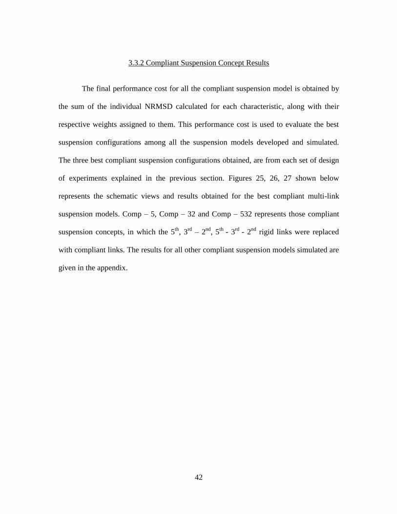
3.3.2 Compliant Suspension Concept Results
The final performance cost for all the compliant suspension model is obtained by
the sum of the individual NRMSD calculated for each characteristic, along with their
respective weights assigned to them. This performance cost is used to evaluate the best
suspension configurations among all the suspension models developed and simulated.
The three best compliant suspension configurations obtained, are from each set of design
of experiments explained in the previous section. Figures 25, 26, 27 shown below
represents the schematic views and results obtained for the best compliant multi-link
suspension models. Comp – 5, Comp – 32 and Comp – 532 represents those compliant
suspension concepts, in which the 5th
, 3rd
– 2nd
, 5th
- 3rd
- 2nd
rigid links were replaced
with compliant links. The results for all other compliant suspension models simulated are
given in the appendix.

43
Figure 25 Compliant multi-link suspension and its performance characteristics with compliant
5th
link

44
Figure 26 Compliant multi-link suspension and its performance characteristic for compliant 3rd
and 2nd
link

45
Figure 27 Compliant multi-link suspension and its performance characteristic for compliant 5th
,
3rd
and 2nd
46
3.4 Chapter Summary
This chapter discussed the compliant suspension concept designed for a generic
multi-link suspension. The compliant suspension concept was aimed at investigating the
potential use of compliant elements within the suspension which integrates the functions
of energy storage mechanism and kinematic guidance for wheels. The reference
suspension model was built in ADAMS, which included design of a non-linear spring
with reference to an existing vehicle which uses multi-link rear suspension. Simulations
were performed on the reference multi-link suspension to obtain a reference data for all
the compliant suspension concepts designed later. Design of compliant multi-link
suspensions were carried out by replacing individual and multiple kinematic rigid links
along with the springs, by simple compliant links. Design of compliant members was
focused on using composite materials instead of the regular steel leaf springs. These
compliant suspension concepts with some assumptions made on the design, were
simulated and the resulting performance characteristics were compared against the
reference multi-link suspension results. Design of compliant multi-link suspension was
explored by replacing multiple combinations of rigid links with compliant links to check
for its kinematic performance against the reference suspension. Since the effect of
kinematics of the suspension is nearly unaltered with the stiffness of the compliant link,
modifications were done to the geometry of the compliant link to match the vertical
compliance of the reference suspension. Deviation errors for each performance
characteristic was non-dimensionalised to calculate the overall performance (cost)
evaluation of each compliant multi-link suspension designed. Finally the best compliant

47
multi-link suspensions with individual and multiple links replaced was presented for
further optimization of certain performance characteristic like the toe angle deviation
following a vertical displacement of the wheel.

48
CHAPTER 4
COMPLIANT SUSPENSION CONCEPTS FOR A REFERENCE VEHICLE
4.1 Introduction
In this chapter we build on results obtained on a generic multi-link rear
suspension in the previous chapter, by focusing on implementation of compliant members
in the rear suspension of a reference high performance vehicle. The multi-link rear
suspension of the reference vehicle was modeled in MSC ADAMS and the model is
validated against results from K&C tests conducted on the reference vehicle. The
suspension model was then used to iterate on compliant link suspension variants. The
suspension analyzed the most includes a compliant ternary link upper arm replacing the
rigid binary link upper arm in the reference suspension.
This chapter starts by describing the existing suspension and follow that up with a
detailed simulation based analysis of the compliant suspension. We discuss concept
evaluation using simulation and tests conducted on a mock-up of the proposed compliant
link suspension.
4.2 Description of the reference suspension model
The multi-link rear suspension for the reference vehicle consists of a longitudinal
arm with the wheel carrier as an integral part and 2 lateral arms extending from the wheel
carrier along with a spring and damper system. Figure 28 shows a schematic of the
reference suspension model built in ADAMS.

49
Figure 28 Schematic of the reference suspension
A virtual model of the reference rear suspension was built in multi-body dynamics
simulation software (MSC ADAMS). The complete kinematic model built along with
springs and bushings as shown in Figure 28 were simulated in ADAMS.
Once the results from the simulation and experiments conducted on a test rig were
matched satisfactorily, new compliant suspension concepts were developed. The
complete design process for the compliant link suspension concept and the final
recommendations are explained in section 4.3.2.
4.3 Development of compliant suspension
The design process for the new compliant suspension concepts was initiated by
having an insight of the functioning of basic compliant element mechanisms. Novel
compliant elements such as using a hybrid universal joint or a ternary link for the
replacement of rigid links were considered. The hybrid universal joint consists of two
Bushings
Lower control arm
Upper control arm
Wheel carrier
Longitudinal
control arm
Spring and
damper
50
rigid links with elastomer filled in between the two rigid links. Some of the advantages of
using a hybrid universal joint are localized deformation and large range of motions. (27).
Another compliant solution considered was to use a compliant ternary link instead of
compliant binary link explained in the previous chapter, which replaces rigid links for
kinematic guidance and energy storage.
4.3.1 Compliant suspension concepts considered
Compliant suspension concepts for the reference suspension were developed
based on the design approaches mentioned in the previous section. A brief description of
the design and their schematic are discussed below.
A range of compliant suspension concepts were initially considered to replace the
rear suspension of the reference vehicle. A brief description of the design and their
schematics of a few of them are included below.
I. Sliding clip concept
The sliding clip suspension concept was developed based on a simple design
which works on a similar principle as an inverted nail clipper. Figure 29 shows the
schematic of an inverted nail clipper and the suspension concept developed.

51
Figure 29 Sliding clip concept
This suspension concept consists of an upper arm, lower arm and a central arm
connecting both the upper and the lower arm. The central arm, being the compliant
member is fixed outboard to the upper arm and is pinned in-board. The lower control arm
which is also a compliant member has a pivot point on the flexible central member and
connects to the wheel carrier. During bump and rebound motions of the wheel carrier, the
lower arm pivots about the compliant link, bending it and sliding along the pin attached
to the upper arm. The distance between the upper arm and the lower can be used to
control the vertical displacement of the wheel carrier, thereby making it suitable to
different applications. During vertical displacement of the wheel carrier, energy is stored
by the centre compliant member and the lower compliant member which acts as leaf
springs in series connected to each other at an offset distance. A laterally and
longitudinally inclined arm can be provided additional longitudinal and lateral support for
this suspension. Some of the drawbacks of this suspension concept include the sliding
friction associated with the pin, during wheel motions and the effect of longitudinal loads
on the suspension. The longitudinal force experienced by the suspension is directly

52
transferred to the intersection of the central arm and the pin leading to wear issues at the
intersection of the lower and central arm.
II. Binder clip concept
The binder clip suspension concept was developed based on a similar working
principle of a paper binding clip. Figure 30 shows the paper binder clip and the compliant
suspension concept design.
Figure 30 Binder clip concept
This suspension concept consists of an upper rigid member, which could act as
the upper arm for either individual suspension or as an axle supporting both right and left
wheel suspensions. The compliant member is in the form of a C-shaped member which is
similar to the complaint member in the paper binding clip and can be stamped into a
single piece. The compliant member is fixed to both the upper and the lower arm, where
the lower arm connects to the wheel carrier. During the vertical displacement of the
wheel carrier, the lower control arm flexes the C-shaped complaint member to expand,
thereby acting as an energy storage member. Since the lower control arm can be assumed
to act like a pivot at the chassis connection end of the suspension, higher camber angles

53
can be achieved during vertical displacement of the wheel carrier. In this case the C-
shaped compliant member can also be used to limit the rebound motion of the
suspension. One of the drawbacks of this suspension is the small range of motion
obtained during bounce motions of the suspension with higher camber angles. Ride
comfort and wear are also some of the issues associated with this suspension concept.
III. Cross-leaf spring concept
This suspension concept was developed by combining the traditional methods of
springing using transverse and longitudinal leaf springs. Figure 31 shows the cross-leaf
spring suspension concept developed.
Figure 31 Cross leaf spring
This suspension concept consists of a semi-elliptic longitudinal leaf spring with
one end connected to the chassis and the other end connected to the wheel carrier and the
transverse leaf spring. The transverse leaf spring can either be a quarter-elliptic leaf
spring or a semi-elliptic transverse leaf spring extending to the other end also. Compliant
members with varied stiffness can also be used for suitable applications. The combined

54
effect of both the longitudinal and the transverse leaf spring contribute to the springing
effect and the energy storage mechanism during vertical motion of the wheel carrier. This
suspension concept can be referred to as a fully compliant suspension system. Shackles
and toe control arms can be used to refine the response of the suspension. A longitudinal
lower arm can be used as an additional member to support traction and braking forces.
The drawback of this suspension is the semi-independent behavior of the suspension. If
the transverse control arm is a quarter elliptic leaf spring, the lower control arm behaves
like a simple cantilever beam accumulating large stresses in it. Since only leaf springs are
used in this suspension concept, control of kinematics to the desired level may be an
issue.
IV. Leaf springs and twist beam
This suspension concept is developed based on the twist beam suspension. Figure
32 shows the twist beam design with leaf springs.
Figure 32 Leaf spring and twist beam

55
A typical twist beam suspension uses springs for its energy storage and twist
beam which goes into torsion during vertical motion of the suspension. This suspension
concept, apart from a typical leaf spring uses a C-shaped compliant member in the
longitudinal direction or a ternary link in the lateral direction to store energy. With this
design, packaging space is reduced and the use of a lateral compliant arm provides lateral
support behind the contact patch and reduces lateral compliance oversteer. The main
disadvantage of this suspension is the packaging issue with the compliant member taking
up some part of the trunk space. Higher toe angles achieved would also contribute to the
drawback of this suspension system.
V. Ternary link and trailing arm concept
This suspension concept was developed as a variant to the existing suspension of
the reference vehicle. Figure 33 shows the leaf spring trailing arm suspension concept.
Figure 33 Ternary link and trailing arm
The leaf spring and trailing arm concept consists of an upper (or lower) transverse
leaf spring or a compliant member instead of the transverse rigid trailing arm. The upper
(or lower) compliant member provides energy storage and wheel guidance during vertical
motion of the wheel carrier. Flexure members and leaf spring ternary links can also be

56
used instead of the standard leaf spring for the upper arm of the suspension. This
suspension system would weigh less than the original reference suspension without any
compromise in the performance of the suspension. Shackles can be used at the chassis
connection point of the compliant member to allow for lateral elongation during bending
of the compliant member. The major advantage of this suspension system is that similar
performance characteristics can be achieved with the assigned package space used for the
original suspension.
4.3.2 Recommended compliant suspension design
Figure 34 shows the schematic of the ternary complaint link used for the design of
compliant suspension concept for the reference vehicle.
Figure 34 Schematic of ternary link
Wheel carrier
connection
point
Fulcrum
point
Chassis
connection
point Fulcrum
point
Chassis
connection
point

57
The term ternary link as one of the compliant solution considered is a simple link
with three connections associated with it. One end of the ternary link is connected to the
chassis through the shackle while the other end of the ternary link is connected to the
wheel carrier and the intermediate fulcrum pivot point on the ternary link is also
connected to the chassis. The intermediate fulcrum pivot point on the ternary link can be
varied to obtain a shorter effective length of the compliant member from the fulcrum to
the wheel carrier controlling the kinematics of the suspension. The distance behind the
fulcrum allows the compliant member to have a longer effective length to accommodate
for large range of motions. Bending stresses are distributed throughout the length of the
link due to the effective longer length of the complaint link and also strain energy is
stored throughout the length of the link. Control over the stiffness of the compliant link
can be achieved for a given range of motion by moving the fulcrum point or tapering the
thickness of the compliant link from the chassis connection point. Shackles are used to
accommodate for change in effective length of the compliant ternary link during its
motion.
Concept 4 which is the ternary link with trailing arm suspension was chosen
among all the other compliant suspension designs for further development. The detailed
explanation of the compliant suspension concept is described below.
Concept 4 chosen is a variant of the reference suspension. Figure 35 explains the
modifications done to the reference suspension to arrive at its compliant counterpart.

58
Figure 35 Reference suspension and its compliant suspension concept
The upper arm of the reference suspension was replaced by a compliant ternary
link as shown in figure 35. This suspension concept has the dual functionality of both the
energy storage and wheel guidance mechanism into a single compliant ternary link. The
bushings at either ends of the upper arm in the reference suspension is replaced by pin
joints on the compliant ternary link. The fulcrum point shown in the figure 35 is an
intermediate joint location on the compliant ternary link which is connected to the
chassis. Shackle is used to connect the compliant ternary link with the chassis. The length
of the compliant link from the fulcrum point to the wheel carrier decides the amount of
camber deviation during suspension vertical motion. The compliant member used for the
ternary link was made up of composite material. The ADAMS model of the compliant
suspension concept developed is as shown below with positions of the wheel carrier.
Fulcrum point
Shackle

59
Figure 36 Compliant suspension concept, at its ride height
Figure 37 Compliant suspension concept, at its rebound position

60
Figure 38 Compliant suspension concept at its full bounce position
Figure 36, 37, 38 shows the compliant suspension concept developed at ride
height (reference height), complete rebound position and complete bounce position
respectively.
4.3.3 Analysis of proposed suspension concept
This section discusses the results obtained from simulations performed on the
compliant multi-link suspension concept developed for the reference suspension and
mock-up of the suspension concept which uses an aftermarket fiberglass leaf spring, for
the compliant member. The design of the compliant member was converged after
numerous simulations performed in ADAMS and ANSYS. Apart from the shape of the
compliant link, the design of experiments included variations in the length of the
compliant member, in the locations of the effective pivot point of the ternary link and in
the orientation of the complaint member. Once the final design was accepted, further

61
validation of the compliant suspension model developed by building a mock-up of the
compliant suspension concept.
Other suspension performance characteristics are compared against the reference
data. Even though the complete vertical displacement of the suspension is considered to
be 80 mm in bounce and rebound motions, the compliant member performance was
restricted to a minimal vertical displacement due to constraints in the test fixture.
Individual performance characteristics for the compliant suspension are explained below
which uses a curved ternary link with shackles at the chassis connection end.
1. Camber angle v/s vertical displacement
The figure 39 below shows the change in camber angle with respect to vertical
displacement for the reference data, mock-up and simulations carried out in ADAMS. It
can be seen that the camber angle deviation for the test conducted on the curved
compliant member is in accordance with the mock-up as well as test data for the
reference suspension.

62
Figure 39 Camber change v/s vertical displacement
2. Vertical force v/s Vertical deflection
The figure shown below presents the results obtained for the vertical force v/s
vertical deflection of the compliant link suspension concept. It can be inferred from
figure 40 shown below that the aftermarket compliant link is close to the spring rate used
currently on the high performance automobile. ADAMS simulation gives a satisfactory
result in accordance with the reference data, but deviates from the results from the mock-
up as shown in figure 40.
-1.5
-1
-0.5
0
0.5
1
1.5
-1.5 -1 -0.5 0 0.5 1 1.5
No
rma
lize
d v
erti
cal
dis
pla
cmen
t
Normalized camber deviation
Camber change v/s Vertical displacement
Compliant link suspension mock-up
testCompliant link suspension simulation
Reference suspension

63
Figure 40 Wheel loads v/s vertical deflection
One of the possibilities for this deviation could be the assumed material property
of the compliant member being used to simulate the suspension. Due to uncertainty in the
material property of the compliant member used, further simulations conducted on the
compliant link with its modified material property showed very close match with the
mock-up, the result of which is shown in figure 41.
-1.2
-1
-0.8
-0.6
-0.4
-0.2
0
0.2
0.4
0.6
0.8
1
0 0.2 0.4 0.6 0.8 1 1.2
No
rma
lize
d v
erti
cal
def
lect
ion
Normalized wheel loads
Wheel loads v/s vertical deflection
Refernce suspension
Compliant link suspension mock-up
testCompliant link suspension simulation

64
Figure 41 Wheel load v/s vertical deflection with change in material property
3. Lateral force response
Figure 42 below shows the lateral force response of the compliant multi-link
suspension model.
-1.5
-1
-0.5
0
0.5
1
0 0.2 0.4 0.6 0.8 1 1.2
No
rma
lize
d v
erti
cal
def
lect
ion
Normalized wheel loads
Wheel loads v/s vertical deflection
Reference suspension
Compliant link suspension mock-up test
Compliant link suspension simulation
Compliant link suspension simulation with
change in material property

65
Figure 42 Lateral wheel load v/s lateral displacement
It is clear from figure 42 shown above that the lateral force response for the
compliant link suspension developed for the reference OEM suspension is matching well
with the data obtained for the reference suspension. The lateral force response is
measured from the reference position of the suspension in ADAMS.
4. Longitudinal force response
Figure 43 below shows the longitudinal force response for the compliant link
suspension.
-1.5
-1
-0.5
0
0.5
1
1.5
-1.5 -1 -0.5 0 0.5 1 1.5
No
rm
ali
zed
la
tera
l lo
ad
Normalized lateral displacement
Lateral displacement v/s Lateral wheel load
Compliant link suspension
simulation
Reference suspension

66
Figure 43 Longitudinal wheel loads v/s longitudinal displacement
The compliant link exhibits low stiffness in the longitudinal direction as
compared to the longitudinal compliance of the reference suspension. The ternary
compliant link chosen to build the mock-up of the suspension has not been optimized to
perform better for longitudinal loads acting on the suspension. Further development of
the ternary compliant link includes modifications to the thickness of the compliant link
for a given stiffness of the material to attain the required longitudinal compliance.
5. Toe angle v/s vertical displacement
Figure 44 below shows the deviation in toe angle with respect to the vertical
deflection of the wheel carrier.
-1.2
-1
-0.8
-0.6
-0.4
-0.2
0
-1.2 -1 -0.8 -0.6 -0.4 -0.2 0
No
rma
lize
d l
on
git
ud
ina
l lo
ad
Normalized longitudinal displacement
Longitudinal load v/s Longitudinal wheel load
Reference suspension
Compliant link
suspension simulation

67
Figure 44 Toe change v/s vertical displacement
The toe angle deviation for the compliant link deviates from the reference
suspension. It is also observed that the toe angle deviates from the reference data even for
different sets of experiments including using a straight compliant member and also for
optimizing the chassis connection point for the compliant link.
During the design phase of the ternary compliant link for the compliant
suspension, simulations were also conducted on a straight ternary link to check for its
kinematics. Results obtained from the straight ternary link are given below.
1. Camber angle v/s vertical displacement
-1.5
-1
-0.5
0
0.5
1
1.5
-0.8 -0.6 -0.4 -0.2 0 0.2 0.4 0.6 0.8 1 1.2
No
rma
lize
d v
erti
cal
def
lect
ion
Normalized toe change
Toe change v/s vertical displacement
Reference suspension
Compliant link suspension
simulation
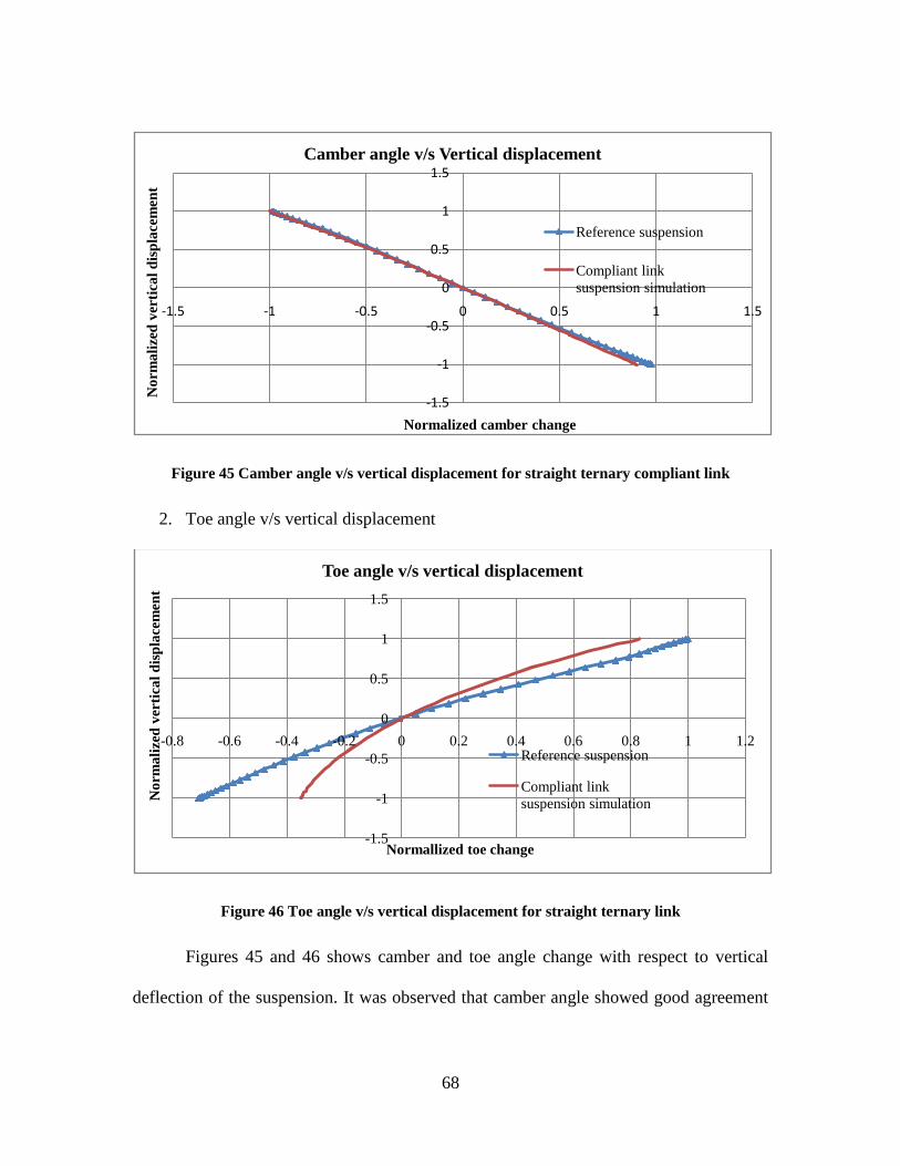
68
Figure 45 Camber angle v/s vertical displacement for straight ternary compliant link
2. Toe angle v/s vertical displacement
Figure 46 Toe angle v/s vertical displacement for straight ternary link
Figures 45 and 46 shows camber and toe angle change with respect to vertical
deflection of the suspension. It was observed that camber angle showed good agreement
-1.5
-1
-0.5
0
0.5
1
1.5
-1.5 -1 -0.5 0 0.5 1 1.5
No
rma
lize
d v
erti
cal
dis
pla
cem
ent
Normalized camber change
Camber angle v/s Vertical displacement
Reference suspension
Compliant link
suspension simulation
-1.5
-1
-0.5
0
0.5
1
1.5
-0.8 -0.6 -0.4 -0.2 0 0.2 0.4 0.6 0.8 1 1.2
No
rma
lize
d v
erti
cal
dis
pla
cem
ent
Normallized toe change
Toe angle v/s vertical displacement
Reference suspension
Compliant link
suspension simulation

69
with the reference data, while toe angle change was found to be deviated to a smaller
extent with very low toe change during rebound motion of the suspension. Since the
aftermarket complaint link obtained from the local manufacturer had initial curvature to
it, the design was concentrated on finding the optimized design for the curved compliant
ternary link
Apart from simulations carried out on a straight ternary compliant link, several
constraints on the compliant link suspension were modified to see the effects of those on
the toe angle deviation. Figure 47 shows one such design of experiments conducted on
the compliant suspension model. In this simulation, the length of the ternary compliant
link was shortened compared to the length of the compliant link used in the
recommended suspension and also the chassis connection point of the compliant member
was shifted by 125, 155, 168 mm towards the rear. Results show that change in the
location of the chassis connection point of the ternary compliant link towards the rear
made the toe deviation better in rebound motion, whereas no change is observed in
bounce motion.

70
Figure 47 Toe angle v/s vertical displacement for modified chassis connection point
4.4 Chapter summary
This chapter discussed the compliant suspension concepts designed for a
reference rear suspension of a high performance vehicle. Concepts designed were based
on results obtained from simulations performed on a generic multi-link suspension
model. Complaint suspension design was performed by looking into different compliant
elements that could be possibly used to build a compliant suspension model. A variant of
the reference suspension was chosen over a few compliant suspension concepts designed
in which the upper arm of the reference suspension was replaced by a ternary complaint
member thereby integrating the functions of energy storage and wheel guidance
mechanism. Numerous simulations were carried out in ADAMS, to check for its
performance characteristics against the reference suspension data. A mock-up of the
-1.5
-1
-0.5
0
0.5
1
1.5
-0.8 -0.6 -0.4 -0.2 0 0.2 0.4 0.6 0.8 1 1.2
No
rma
lize
d v
erti
cla
l d
isp
lace
men
t
Normalized toe change
Toe angle v/s vertical displacement
Compliant link suspension simulation (125 mm)
Reference suspension
Compliant link suspension simulation (155 mm)
Compliant link suspension simulation (168 mm)

71
compliant suspension concept was built using an aftermarket compliant member to
validate the simulation results. Simulation results for the ternary compliant member show
good agreement with camber deviation and lateral force response. The vertical force
response for the compliant link was also matched satisfactorily with the data from the
mock-up after iterating on the material property of the compliant link to account for
uncertainty the material property for the aftermarket product used for creating the mock-
up. The longitudinal force response showed higher deviations from the reference
suspension. Toe angle deviation was also significant. It is expected that the toe response
and longitudinal compliance could be improved with further optimizations of the
compliant link suspension design, such as with the use of straight compliant links of
appropriate dimensions.

72
CHAPTER – 5
CONCLUSIONS AND FUTURE WORK
This chapter provides a summary of the conclusions drawn from the research
conducted on compliant suspension concepts. It also outlines some remaining areas that
need to be addressed to enhance the performance of the compliant suspension concepts.
5.1 Conclusions
The first objective of this thesis was to address the problem of integrating the
functions of energy storage and wheel guidance mechanism into a single compliant
member. One of the possible ways of achieving this was to replace both the springs
which provide energy storage but not wheel guidance, and kinematic rigid links which
provides wheel guidance but not energy storage, by a single compliant member within the
suspension. Earlier forms of energy storage members were the leaf springs, where they
contributed partially to the kinematics of the suspension. Leaf springs were stacked up to
achieve the required vertical compliance, thereby increasing the weight of the suspension
system. Compliance was achieved by making the leaf spring progressively wide and the
load carrying capacity was accomplished with thicker cross sections, which again
contributed to increased space and weight. This thesis has satisfactorily addressed the
objective, by replacing kinematic rigid links and the spring by a binary and ternary
compliant link. The binary compliant link used on the generic multi-link suspension was
constrained to act as a simple cantilever beam, which successfully reproduced the

73
kinematics and stiffness illustrated by the reference suspension model. The binary link
showed greater stress accumulation in the beam as compared to the ternary link. The
ternary link allows for design adjustable ranges of motions and stiffness by modifying the
fulcrum point on the link. Effective storage of strain energy and distribution of bending
stresses are the main advantages of the ternary compliant link due to effective longer
length of the link which extends from the fulcrum point to the chassis. ADAMS
simulation results on compliant link suspensions analyzed shows good match with results
from reference suspensions and also a mock-up of the compliant suspension. This proved
the potential use of compliant links in the suspensions considered.
The second objective of this thesis was to develop compliant suspension concepts
achieving similar or better performance characteristic compared to the reference
suspension configuration chosen. Simulation results from chapter 3 shows promising
results with the use of composite compliant members, replacing springs and kinematic
rigid links on a generic multi-link suspension model. The best possible solutions to the
compliant multi-link suspension with the assumed design constrains was obtained by
varying the stiffness of the compliant link being replaced with their respective rigid links.
The results obtained also indicate that the highest deviation in the results from the
reference suspension was in the toe angle characteristic. The trend of the curve for toe
characteristic is a function of the dimensions and orientation of the compliant links. The
total vertical stiffness of the compliant multi-link suspension can be summarized as the
sum of the stiffness of each kinematic rigid links replaced, which is a function of its
geometric dimensions with fixed material properties.

74
Furthermore, compliant suspension concepts were developed for a reference
existing suspension. Ternary compliant link with trailing arm suspension concept was
chosen for further validation among compliant suspension concepts designed. Simulation
results from ADAMS on both the geometric variations of the ternary compliant link and
mock-up presented in chapter 4, signifies that the developed compliant suspension
concept clearly achieves similar characteristics compared to the existing reference
suspension with optimization of compliant links on characteristics like the toe angle.
5.2 Future work
The use of ternary links showed better results compared to binary links in
carrying out the functionalities of energy storage and kinematic guidance for compliant
suspensions. It was seen that both the binary and ternary compliant links showed great
deviation in toe angle measurements. Performance of the compliant suspension model
can be further enhanced with focus on the following issues.
Complaint suspension concepts designed for generic multi-link suspensions can
be further investigated for optimal results by considering ternary links with different
geometric profiles along with the use of shackles at the chassis connection end. Bushings
can be used on the suspension models to validate its performance under lateral and
longitudinal loads on the suspension. Optimization of the compliant links and the chassis
connection points can also be carried out to control the toe angle deviations.
Ternary links used on the compliant suspension model developed for an existing
rear suspension also showed greater toe angle deviations. Toe control links can be

75
incorporated in the compliant suspension system, which can better control the large toe
angles. Other performance characteristics can be checked with the use of a straight
ternary link on the mock-up of the compliant suspension built, to compare it against the
ADAMS simulation and the reference suspension. Apart from upper control arms, lower
control arm of the suspension can also be replaced with ternary links and checked for its
overall performance. The current compliant link used can further be optimized for the
effect of longitudinal forces on the suspension either by modifying the material property
of the material or its geometric profile.
Composite materials used for the production of compliant links can also be
considered for further research. Individual orthotropic properties of the composite
materials could be modified to optimize its effect on control forces acting on the
suspension and also to tune the kinematics of the suspension.

76
APPENDIX
Simulation results for generic multi-link suspension models
Figure 48 Compliant multi-link suspension performance characteristic with compliant 1st link
Figure 49 Compliant multi-link suspension performance characteristic with compliant 2nd
link

77
Figure 50 Compliant multi-link suspension performance characteristic with compliant 3rd
link
Figure 51 Compliant multi-link suspension performance characteristic with compliant 4th
link

78
Figure 52 Compliant multi-link suspension performance characteristic with compliant 2nd
and
1st link
Figure 53 Compliant multi-link suspension performance characteristic with compliant 3rd
and
1st link

79
Figure 54 Compliant multi-link suspension performance characteristic with compliant 4th
and
1st link
Figure 55 Compliant multi-link suspension performance characteristic with compliant 4th
and
2nd
link

80
Figure 56 Compliant multi-link suspension performance characteristic with compliant 4th
and
3rd
link
Figure 57 Compliant multi-link suspension performance characteristic with compliant 5th
and
1st link

81
Figure 58 Compliant multi-link suspension performance characteristic with compliant 5th
and
2nd
link
Figure 59 Compliant multi-link suspension performance characteristic with compliant 5th
and
3rd
link

82
Figure 60 Compliant multi-link suspension performance characteristic with compliant 5th
and
4th
link
Figure 61 Compliant multi-link suspension performance characteristic with compliant 3rd
, 2nd
and 1st link
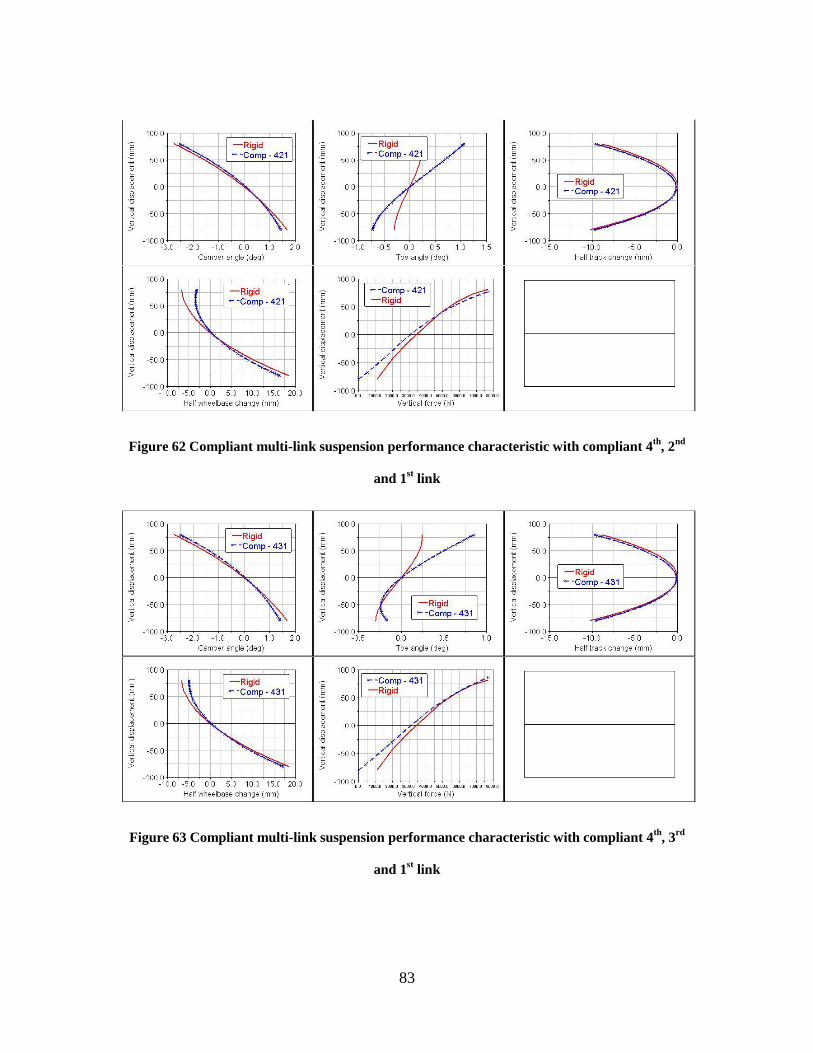
83
Figure 62 Compliant multi-link suspension performance characteristic with compliant 4th
, 2nd
and 1st link
Figure 63 Compliant multi-link suspension performance characteristic with compliant 4th
, 3rd
and 1st link

84
Figure 64 Compliant multi-link suspension performance characteristic with compliant 4th
, 3rd
and 2nd
link
Figure 65 Compliant multi-link suspension performance characteristic with compliant 5th
, 2nd
and 1st link

85
Figure 66 Compliant multi-link suspension performance characteristic with compliant 5th
, 3rd
and 1st link
Figure 67 Compliant multi-link suspension performance characteristic with compliant 5th
, 4th
and 1st link

86
Figure 68 Compliant multi-link suspension performance characteristic with compliant 5th
, 4th
and 2st link
Figure 69 Compliant multi-link suspension performance characteristic with compliant 5th
, 4th
and 3rd
link

87
REFERENCES
1. ULSAS - Improving Performance Through Light Weight Automotive Suspension
Systems: Phase 1 - Benchmarking and Initial Design Concepts. Nicholas
J.Sampson, David A. Thomas, Peter Rawlinson. Detroit : Society of
Automotive Engineering, Inc., 1999. SAE International Congress and Exposition.
2. Allred, Timothy M. Compliant Mechanism Suspensions - Thesis. Brigham
Young University, Utah : s.n., 2003.
3. Gillespie, Thomas D. Fundamentals of Vehicle Dynamics. s.l. : Society of
Automotive Engineers, Inc., 1992
4. Howell, Larry L. Compliant Mechanisms. s.l. : Wiley-Interscience Publication,
2002
5. [Online] http://www.ossur.com/prosthetics/feet/lpvariflex
6. Development of Commercially Viable Compliant Mechanisms using Pseudo-Rigid
Body Model: Case Studies for Parallel Mechanisms. Christopher A. Mattson,
Larry L. Howell, Spencer P. Magleby. 2004, Journal of Intelligent Systems and
Structures, pp. 195 – 202
7. Compliant mechanism configurations for vehicle suspension systems. Timothy
Allred, Larry L. Howell, Spencer P. Magleby, Alexandre E. Guerinot. Anaheim, USA : s.n., 2004. ASME International Mechanical Engineering
Congress and Exposition.
8. [Online] http://www.wikipedia.org/
9. Development of the Liteflex Suspension Leaf Spring. Bruce E. Kirkham, Leo S.
Sullivan, Robert E. Bauerle. Detroit, USA : Society of Automotive Engineers,
Inc., 1982. SAE International Congress and Exposition
10. Composite Integrated Rear Suspension. C. J. Morris (Ford Motor Company).
1986, Composite Structures, pp. 233 – 242
11. Compliance and Friction in Elastic and Mechanical Joints and Race Car
Suspensions. Matthew S. Zipfel, Albert R. George. Dearborn : Socciety of
Automotive Engineers, Inc., 2006. SAE Motorsports Conference and Exhibition

88
12. Barney Gerrard (Magneti Marelli). [Online] 2005.
http://www.vehicledynamics-expo.com/05vdx_conf/pres/day1/gerrard.pdf
13. http://www.magnetimarelli.com/english/suspension_ricerca_sospensioni.php
14. The Equivalent Elastic Mechanism: A Tool for the Analysis and the Design of
Compliant Suspension Linkages. M. B. Gerrard (Magneti Marelli). Detroit :
Society of Automotive Engineers, Inc., 2005. SAE World Congress
15. Barney Gerrard (Magneti Marelli). [Online] 2006.
http://www.vehicledynamics-expo.com/06vdx_conf/pres/day_1/gerrard.pdf
16. Light and Low Cost Composite Compression C Springs for Vehicle Suspension.
Max A. Sardou, Patricia Djomseu. Detroit : Society of Automotive
Engineering, Inc., 2000. SAE World Congress
17. Light Composite Elliptic Springs for Vehicle Suspension. E. Mahdi, O. M. S.
Alkoles, A. M. S. Hamouda, B. B. Sahari, R. Yonus, G. Goudah. 2006,
Compsite Structures, pp. 24-28
18. Development of FRP Rear Axle Components. Ingo Kuch, Gudrun Delonge-
Immik. Detroit : Society of Automotive Engineers, Inc., 1991. SAE International
Congress and Exposition
19. Automobile Leaf Springs from Composite Materials. Al-Qureshi, H. A. 2001,
Journal of Materials Processing Technology, pp. 58-61
20. J. Reimpell, H. Stoll, J. W. Betzler. The Automotive Chassis. s.l. : Society of
Automotive Engineers, Inc., 2001
21. Donald Bastow, Geoffrey Howard, John P.Whitehead. Car Suspension and
Handling. s.l. : Society of Automotive Engineers, Inc., 2004
22. William F. Milliken, Douglas L. Milliken. Race Car Vehicle Dynamics. s.l. :
Society of Automotive Engineers, Inc., 1995
23. Elastokinematic modeling and study of five-rod suspension with subframe. Jozef
Knapczyk, Michal Manisowski. 2006, Mechanism and Machine Theory, pp.
1031-1047

89
24. Rear Wheels Multi-Link Suspension Synthesis with the Application of a "Virtual
Mechanism". Wojciech Wach, Jozef Struski. Detroit, USA : Society of
Automotive Engineers, Inc., 2006. SAE World Congress
25. J. K. Davidson, K. H. Hunt. Robots and Screw theory. s.l. : Oxford University
Press, 2004
26. Mechanical Behavior for 3-D Orthogonal Woven E-Glass/Epoxy Composites.
Ping Tan, Litong Tong, Grant P. Steven. 2001, Journal of Reinforced Plastics
and Composites
27. Vincent Lee, John C. Ziegert. Hybrid Bi_Directional Flexure Joints.