complexity from simplicity manipulation of crystal gr owth ... · manipulation of crystal gr owth...
TRANSCRIPT
17 MAY 2013 VOL 340 SCIENCE www.sciencemag.org 822
PERSPECTIVES
Complexity from Simplicity
MATERIALS SCIENCE
Elias Vlieg
Manipulation of crystal growth conditions
results in the controlled formation of complex
micrometer-scale shapes.
with the corresponding detector signal to
create a number of weighted images, from
which a full image of the object can again be
reconstructed.
Sun et al. have combined these ideas
and have shown that a full 3D image can be
recorded with only a few single-pixel bucket
photodetectors and intelligent illumina-
tion. In their scheme, the known illumina-
tion source is a rapidly changing checker-
board of black and white squares generated
by a digital projector, such as that used for
project presentations (see the fi gure). How-
ever, this elegant experiment is far from the
end of the story. The procedure requires sev-
eral minutes to reconstruct a full 3D image
of a human head. During this time, the head
or object must remain perfectly still, much
like early photography with low-speed glass
plates. This limitation, mainly caused by the
refresh rate of the digital projector, results in
relatively slow data acquisition rates. Reduc-
tion of recording times will necessarily
require the development of a new generation
of superfast projectors, or possibly the use of
high-repetition laser sources.
We can easily envisage that the techno-
logical requirements for reducing the record-
ing times in Sun et al.’s technique will soon
be resolved, enabling the real-time record-
ing of 3D images using only single pixels.
One of the most promising applications is
the capability of 3D imaging in wavelength
regions limited by current detector array
technologies. This blend of simple ideas and
complex physics by Sun et al. combines to
give us a beautiful new way of seeing the
world. It would seem that the answer to the
question “How simple can we make a 3D
imaging system?” appears to be “Discon-
certingly so.”
References
1. B. Sun et al., Science 340, 844 (2013).
2. D. V. Strekalov, A. V. Sergienko, D. N. Klyshko, Y. H. Shih,
Phys. Rev. Lett. 74, 3600 (1995).
3. R. S. Bennink, S. J. Bentley, R. W. Boyd, Phys. Rev. Lett.
89, 113601 (2002).
4. A. Gatti, E. Brambilla, M. Bache, L. A. Lugiato, Phys. Rev.
Lett. 93, 093602 (2004).
5. J. H. Shapiro, Phys. Rev. A 78, 061802 (2008).
6. O. Katz, Y. Bromberg, Y. Silberberg, Appl. Phys. Lett. 95,
131110 (2009).
7. Y. Bromberg, O. Katz, Y. Silberberg, Phys. Rev. A 79,
053840 (2009).
10.1126/science.1238415
By studying natural shapes and pro-
cesses, researchers have learned that
the key ingredient to arriving at com-
plexity is the coupling between different pro-
cesses. This coupling leads to self-organi-
zation and is an essential feature of life ( 1).
In biominerals, such as diatom skeletons or
abalone shells, the interplay between cal-
cium carbonate or similar minerals with
organic molecules can lead to highly func-
tional materials with hierarchical architec-
tures and stunning beauty ( 2). On page 832
of this issue, Noorduin et al. ( 3) bring the
man-made design of complex shapes from
simple ingredients to a level of control that
promises applications in fi elds such as optics
and catalysis.
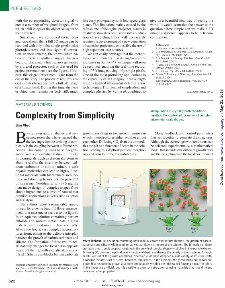
The authors report a remarkably simple
process for growing beautiful fl ower arrange-
ments at a micrometer scale (see the fi gure).
In an aqueous solution containing barium
chloride and sodium metasilicate, a glass
plate is positioned more or less vertically.
After a few hours, very complex microstruc-
tures form, owing to the delicate interplay
between the growth of barium carbonate and
silicate. The formation of these two miner-
als not only changes the local pH in opposite
ways, but their growth rate also depends on
this pH. Silicon also blocks barium carbonate
growth, resulting in two growth regimes in
which microstructures either avoid or attract
each other. Diffusing CO2 from the air modi-
fi es the pH as a function of depth in the solu-
tion, leading to a depth-dependent morphol-
ogy and density of the microstructures.
Many feedback and control parameters
thus act together to generate the structures.
Although the correct growth conditions can
be selected experimentally, a mathematical
model that includes the different growth rates
and their coupling with the local environment
Radboud University Nijmegen, Institute for Molecules and Materials, Heyendaalseweg 135, 6525 AJ Nijmegen, Neth-erlands. E-mail: [email protected]
CO2
Na2SiO
3
BaCl2
Step 1
20°C
Step 2
4°C
Micro-ikebana. In a solution containing both sodium silicate and barium chloride, the growth of barium carbonate and silicate will depend on, as well as infl uence, the pH of the solution. The formation of these crystals is thus strongly coupled, resulting in the growth of complex shapes—tuliplike in the example shown. Diffusing CO2 dictates the pH value as a function of depth and thereby the density of the structures. Through careful control of the growth conditions, Noorduin et al. have designed a wide variety of structures with fl owerlike features such as stems, branches, and leaves. In the example, the green stems and leaves are grown fi rst, followed by growth at a lower temperature, yielding the thick-walled fl owers on top. The colors in the image are artifi cial, but it is possible to grow such structures by using materials that have different colors and other properties.
Published by AAAS
on
May
21,
201
3w
ww
.sci
ence
mag
.org
Dow
nloa
ded
from
www.sciencemag.org SCIENCE VOL 340 17 MAY 2013 823
PERSPECTIVES
(Poly)Combing the Pediatric Cancer Genome for Answers
MEDICINE
Marc Alard Morgan and Ali Shilatifard
Misregulation of the pattern and localization
of histone modifi cations may result in cancer
development.
seems essential to obtain a further under-
standing and control.
Flower shapes have previously been
grown from inorganic materials such as
metal oxides, semiconductors, and silicon
oxide ( 4). The choice of materials is not new
either: García-Ruiz et al. have shown that this
system can generate shapes resembling bio-
logical forms and that the shapes of the old-
est known fossils can also be produced in this
inorganic way ( 5). García-Ruiz et al. have
more recently proposed a model to explain
the shape of such “biomorphs” ( 6).
Noorduin et al. now provide an improved
understanding of the formation process that
allows them to design the resulting shapes at
will and to combine different growth condi-
tions to generate even more complex shapes.
Rather than selecting one set of conditions
and letting the system evolve passively,
the authors change the process conditions
actively, allowing the construction of ele-
ments such as stems, vases, branches, and
leaves.
The growth conditions are changed by
moving the glass plate from one beaker to
the next. By using different tilt angles of
the glass plate in the two beakers, an entire
matrix of conditions is probed at once, allow-
ing the researchers to pick the fl owers they
like best. More sophisticated setups, such as
microfl uidic devices with precise pH, con-
centration, and fl ow control, should enable
the reproducible production of very com-
plex shapes with desirable properties. This
form of bottom-up patterning may become
useful, for example, in the design of cata-
lytic surfaces, where the large surface area
and the confi nement of the reactants may
enhance the catalytic activity ( 7), or in the
growth of three-dimensional metamaterials
with a negative index of refraction that can
be used as optical elements ( 8).
Other routes to generate (sub)microme-
ter-scale architectures in a bottom-up fash-
ion include the combination of nanoparticles
with organic molecules, which can give rise
to self-assembled structures with a complex-
ity that depends on the number of interaction
components ( 9). Properly designed mole-
cules can be self-assembled in supramolecu-
lar structures with a functionality that again
depends on the interaction between the differ-
ent components ( 10). Nanowires can also be
designed so that nanoscale patterning occurs
spontaneously ( 11).
None of these examples, however, com-
bines the simplicity, beauty, and control of
the barium carbonate and silicate system.
For now, Noorduin et al. have focused on
growing fl owerlike structures. More control
will undoubtedly lead to structures that may
be less artistically pleasing, but more tech-
nologically useful.
References and Notes
1. J.-M. Lehn, Angew. Chem. Int. Ed. 52, 2836 (2013).
2. S. Weiner, L. Addadi, J. Mater. Chem. 7, 689 (1997).
3. W. L. Noorduin, A. Grinthal, L. Mahadevan, J. Aizenberg,
Science 340, 832 (2013).
4. For a series of beautiful examples, see www.mrs.org/
science-as-art/.
5. J. M. García-Ruiz et al., Science 302, 1194 (2003).
6. J. M. García-Ruiz, E. Melero-García, S. T. Hyde, Science
323, 362 (2009).
7. J. Ge, J. Lei, R. N. Zare, Nat. Nanotechnol. 7, 428 (2012).
8. C. M. Soukoulis, M. Wegener, Nat. Photonics 5, 523
(2011).
9. H. Cölfen, S. Mann, Angew. Chem. Int. Ed. 42, 2350
(2003).
10. J. A. A. W. Elemans, R. van Hameren, R. J. M. Nolte, A.
E. Rowan, Adv. Mater. (Deerfi eld Beach Fla.) 18, 1251
(2006).
11. R. E. Algra et al., Nature 456, 369 (2008).
10.1126/science.1238619
The rapid expansion of high-through-
put DNA sequencing now enables the
genetic analysis of human diseases at
an unprecedented rate and resolution. In par-
ticular, whole-genome sequencing of rare
childhood diseases promises fundamental
insight into basic developmental processes
and biochemical pathways ( 1). Indeed, this
approach has identifi ed the fi rst mutations in
histones—proteins that package DNA—in
human disease ( 2, 3). About 80% of cases
of diffuse intrinsic pontine glioma (DIPG),
an aggressive, incurable childhood tumor of
the brain stem, harbor these histone muta-
tions. On page 857 of this issue, Lewis et al.
( 4) extend this story by showing that altered
activity of polycomb repressive complex 2
(PRC2), a key developmental regulator of
gene expression, is involved in the patho-
genesis of gliomas carrying these mutant
histones.
The culprit mutations involve a substitu-
tion of lysine 27 to methionine (H3K27M)
in one of two histone H3-encoding genes,
H3F3A (histone H3.3) or HIST1H3B (his-
tone H3.1). Histone proteins form the core
of eukaryotic chromatin, and their post-
translational modifications are associated
with various DNA-based processes includ-
ing transcription ( 5). Lysine 27 of histone H3
is subject to methylation by PRC2, a multi-
protein assemblage essential for repressing
transcription during development ( 6). The
precise function of histone lysine methyla-
tion is a topic of some contention ( 7). Stud-
ies in the fruit fly Drosophila melanogas-
ter suggest that H3K27 modifications are
essential for developmental gene regulation,
as a lysine-to-arginine substitution activates
genes that are normally repressed by PRC2
( 8). The remarkably specifi c nature of the H3
mutation in high-grade (aggressive) pediatric
gliomas points to a connection with lysine 27
modifi cations.
Although the H3K27M mutation is het-
erozygous (occurs in only one of the two
gene copies), there is profoundly reduced tri-
methylation (H3K27me3) of wild-type H3 in
gliomas ( 9), which suggests that the muta-
tion dominantly inhibits PRC2 methyltrans-
ferase activity. Indeed, biochemical studies
by Lewis et al. and others ( 4, 10) show that
the mutant histone binds to the catalytic site
of PRC2 to block enzymatic activity (see the
fi gure). This effect was examined in patient
tumor cells using chromatin immunoprecip-
itation followed by DNA sequencing ( 10).
Global trimethylation of wild-type H3K27
is reduced in these tumor cells. However,
local increases in this modifi cation, accom-
panied by PRC2 occupancy of chromatin,
were observed at sites involved in repress-
ing tumor suppressors, such as p16Ink4A
( 10). These unexpected fi ndings suggest that
the function of mutant H3K27M is more
Stowers Institute for Medical Research, 1000 East 50th Street, Kansas City, MO 64110, USA. E-mail: [email protected]
Published by AAAS
on
May
21,
201
3w
ww
.sci
ence
mag
.org
Dow
nloa
ded
from

Rationally Designed Complex,Hierarchical MicroarchitecturesWim L. Noorduin,1* Alison Grinthal,1 L. Mahadevan,1,2,3,4 Joanna Aizenberg1,2,3,5*
The emergence of complex nano- and microstructures is of fundamental interest, and the abilityto program their form has practical ramifications in fields such as optics, catalysis, and electronics.We developed carbonate-silica microstructures in a dynamic reaction-diffusion system that allowus to rationally devise schemes for precisely sculpting a great variety of elementary shapes bydiffusion of carbon dioxide (CO2) in a solution of barium chloride and sodium metasilicate.We identify two distinct growth modes and show how continuous and discrete modulationsin CO2 concentration, pH, and temperature can be used to deterministically switch betweendifferent regimes and create a bouquet of hierarchically assembled multiscale microstructureswith unprecedented levels of complexity and precision. These results outline a nanotechnologystrategy for “collaborating” with self-assembly processes in real time to build arbitrarytectonic architectures.
Natural patterns and shapes arise in in-numerable ways on a range of scales andhave fascinated artists and scientists alike
(1, 2). Hierarchical nano- and microarchitecturesnot only offer insight into how complex forms canemerge from simple starting materials, but alsounderlie coloration (3), wetting (4), mechanics (5),and other phenomena seen in nature and maytransform optics (6), catalysis (7–9), building con-struction, and many other technologies if we canfind ways to create them synthetically. Using top-down lithography techniques (10), we can direct-lywrite and sculpt three-dimensional (3D) patternsinto a variety of materials, but at small scales thishands-on control translates into a laborious, cost-ly, and often insufficient approach. Self-assemblyfrom the bottom up can generate diverse patternsthrough amuchmore complex evolution of forcesthan we could ever apply by hand (11); however,ceding control over all but the starting materialsleaves little opportunity to fine-tune structures orcontrol stages of hierarchical development, let alonerationally design arbitrary architectures. Strate-gies inspired by biomineralization have been ex-plored as potential routes to controlling growthand self-assembly from the molecular level viatailoredmicroenvironments, epitaxy, and inorganicor organic additives (12–21). Yet although thesestrategies have produced some interesting spheri-cal, spiral, leaflike, and other shapes (22–29), theappearance of various forms in synthetic systemsis often unexpected and not usually based on pre-dictive mechanisms.
The vast majority of efforts to apply biomin-eralization principles to synthetic strategies have,like most nanoscale self-assembly techniques, fo-
cused primarily on defining the initial conditionsor solution composition. Although this approachhas certainly yielded useful insights, it is obviousthat many complex patterns emerge specificallyin response to a dynamic environment. For ex-ample, abrupt switches inmarine shell patterninghave been attributed to changes in conditionsduring growth (1); at a larger scale, bacteria formhierarchically structured communities by chemo-tactically responding to continuously changing chem-ical cues (30). This perspective not only highlightsa major source of complexity and hierarchy cur-rently missing from synthetic strategies, but alsosuggests that we might be able to actively shapeself-assembling structures by manipulating the en-vironment as they grow. This possibility is espe-
cially compelling for systems that develop throughreaction-diffusion processes, where dynamic feed-back between the reaction front and the solutionis the central mechanism of pattern evolution(31–35). Such feedback mechanisms are not onlyproposed to explain a variety of natural forms,but they can also generate patterned precipita-tion in synthetic systems (36). We therefore ex-plore whether mineralized forms can be preciselysculpted and hierarchically assembled into novel,arbitrary architectures through dynamic, ratio-nally programmed modulations of the reactionsolution.
In this work, we demonstrate how the respon-sive growth of BaCO3-SiO2 structures toward oraway from the bulk solution can be exploited toprogram a variety of “elementary” growth pat-terns. We derive sequences of simple, subtle mod-ulations of CO2, pH, and temperature that serveas building strategies for intricate, user-definedmicrostructures of higher order. With the use ofcontinuous and/or stepwise adjustments, we steerthe precipitating reactants via precise sculptingand sequential combinatorial assembly of thedeveloping shapes.
Hypothesis for Structure Evolution in a Fieldof Chemical GradientsOur strategy for dynamically modulating struc-ture evolution is based on the idea that the de-veloping structure will be continuously shapedby a complex spatial field of overlapping chem-ical gradients, created by the interplay betweenthe bulk solution, the reaction front, and poten-tially neighboring structures. We analyze this
1School of Engineering and Applied Sciences, Harvard Uni-versity, Cambridge, MA 02138, USA. 2Wyss Institute for Bio-logically Inspired Engineering, Harvard University, Boston, MA02115, USA. 3Kavli Institute for Bionano Science and Tech-nology, Harvard University, Cambridge, MA 02138, USA.4Department of Physics, Harvard University, Cambridge, MA02138, USA. 5Department of Chemistry and Chemical Biology,Harvard University, Cambridge, MA 02138, USA.
*Corresponding author. E-mail: [email protected](W.L.N.); [email protected] (J.A.)
Fig. 1. Hypothesis for structure evolution in three growth regimes. Schematic representationof the rate of SiO2 (37) (solid gray line) and BaCO3 precipitation (dashed red line) in the range of pH ~8to 12 (A) and anticipated shapes and growth directions (B) resulting from the three proposed growthregimes (see text for details). In all cases, growth will begin with the nucleation of BaCO3, which willlead to the local reduction of pH at the growth front. In regime 1, the associated pH drop brings thestructures to the right side of the silica deposition range (denoted as pHSiO2), giving rise to thecontinuous coprecipitation of BaCO3 and SiO2. The structures will growmost successfully away from oneanother and toward the solution where pH > pHSiO2, whereas other growth directions associated withlower pH become passivated by silica. Depending on the nucleation density, we expect the structures to“blossom” into stems, cones, and hemispherical shapes. In regime 2, the pH drop from carbonate depositionwill lower the pH at the growth front to pH < pHSiO2, whereas the bulk solution remains more alkaline withpH > pHSiO2. In this case, any growth directions toward the higher pH bulk solution will cross the silicaprecipitation region and be blocked, such that the structures are expected to grow most successfully awayfrom the solution, along the interface, or curl down and toward each other where pH remains below pHSiO2following the trail of produced acid. In regime 3, only BaCO3 crystals are expected to form.
17 MAY 2013 VOL 340 SCIENCE www.sciencemag.org832
RESEARCH ARTICLES
on
May
16,
201
3w
ww
.sci
ence
mag
.org
Dow
nloa
ded
from

growth process for the coprecipitation of SiO2
and BaCO3 in an alkaline aqueous solution con-taining Na2SiO3 and BaCl2, where precipitationis triggered by the diffusion of CO2. BaCO3 dep-osition increases with increasing pH, whereasSiO2 deposition takes place in a narrow, optimumpHSiO2 range (Fig. 1A) (37), and mutual feed-back between the two processes may create areaction-diffusion scenario. We hypothesize thatthe pH-dependent feedback between BaCO3 andSiO2 deposition will lead to three distinct growthregimes, each with a characteristic set of mor-phologies, which can be evoked by small changesin the environment, as follows:
Regime 1) Startingwith a high-pHbulk solution(region 1 in Fig. 1A), no silica deposition will takeplace, and the influx of CO2 will trigger the pre-cipitation of BaCO3, according to a simplified reac-tion: Ba2+ + CO2 + H2O → BaCO3 + 2H+. Thereleased H+ will gradually lower the local pH at thegrowth front, until entering the pH range for silicaprecipitation, according to a simplified reaction:SiO3
2– + 2H+→ SiO2 +H2O,which then shifts thereaction equilibrium and solubility back towardBaCO3 precipitation, resulting in the continuouscoprecipitation of BaCO3 and SiO2 (25). This sce-
nario will have several consequences for the de-veloping structure: (i) Crystal growth will bepassivated where silica precipitates, (ii) structuresshould grow most successfully toward the bulksolution where pH is above the range for silicadeposition, and (iii) growth should be inhibitednear the lowered pH of neighboring growth fronts.Depending on the nucleation density, different basicmorphologiesmight then be expected: hemispheresat low nucleation densities, or cones and stem shapesat higher densities, where neighboring diffusionfields steer the structures away from each othertoward regions of higher pH (Fig. 1B).
Regime 2) Lowering the initial bulk pH cangenerate a scenario in which the local pH is be-low the optimum pH for silica formation (pHSiO2),whereas the bulk pH is still above pHSiO2 (region2 in Fig. 1A). In this case, the local decrease inpH due to continuing BaCO3 crystallization pre-vents, rather than promotes the formation of SiO2
close to the growth front, whereas the influx of thebulk solution with pH > pHSiO2 brings the solutioninto the pHSiO2 range and triggers the precipitationof SiO2 that passivates growth. Structures will thenbe expected to growmost successfully away fromthe bulk solution, either along the interface to form
flat sheets or curling down and toward each other topreserve a low pH at the growth front (Fig. 1B).
Regime 3) If the pH of the bulk solution isbelow the pHSiO2 range, only “normal” BaCO3
structures should form (region 3, Fig. 1).
Testing Regime 1: Solution-Directed Growthof Stems, Vases, and CoralsAs a first step toward testing the solution-dependentgrowth of structures in regime 1, we created agradient of CO2 concentrations by vertically po-sitioning an aluminum plate or gold-coated glasssubstrate in a beaker containing an aqueous so-lution of BaCl2 (19.1mM) andNa2SiO3 (8.2mM)at a pH of 11.8 and loosely covering the beakerto let CO2 from the air diffuse into the system(Fig. 2A). The nucleation density of BaCO3, grad-ually decreases with depth, in accord with thedecrease in CO2 concentration. Within 2 hours,the nucleated BaCO3 bundles develop into a denseforest of thin stems at the top of the substrate,where the CO2 concentration is highest (Fig. 2Aand fig. S1). At intermediate depths, the struc-tures instead become vaselike and form coral-likehemispherical shapes toward the bottom. In allcases, the structures grow perpendicular to thesubstrate—that is, toward the bulk solutionwherepH > pHSiO2—and veer away from each other.The basic morphologies and behavior are, thus,consistent with the solution-directed growthhypothesis proposed for regime 1. Yet at the sametime, the intricate wall structures observed in thevases and corals provide another level of com-plexity within each of the basic shapes, support-ing the idea that this growth mechanism alsocontains the seeds for more complex modulations.
Inspection by scanning electron microscopy(SEM) reveals that the walls have a constant thick-ness of ~1 mm, with a consistent thickening ofstems and at the edges of the walls (Fig. 2B). Theconstant wall thickness suggests a 2D growthmechanism, in which precipitation merely occursat the active top edges of the structures while be-ing inhibited by silica at the sides. Selective dis-solution of BaCO3 using HCl (0.5 mol/L) leavesbehind a hollow silica shell (fig. S2), further in-dicating that the silica mainly deposits on andselectively passivates the sides of the walls wherethe pH is lowest (Fig. 2C). This localized silicaprecipitation sets the thickness of the walls be-cause the pH in the middle of the growth front isless buffered than closer to the sides where silicaprecipitation mainly occurs, allowing a new layerof BaCO3 crystals to grow at the top of the walls.The increased thickness at the edges of the wallsand stems is also consistent with solution-directedgrowth: These areas have a larger surface to ac-commodate the silica deposition, resulting in lo-cal thickening (Fig. 2B). The localized feedbackalso produces a uniform 2D growth front by dam-pening the formation of spontaneous protuber-ances. To directly demonstrate that the structuresevolve toward the highest pH, we grew them ina continuous flow that increased the pH at thegrowth front using a microfluidic device. The
Fig. 2. Diversity of structures that grow in regime 1. (A) SEM image of a typical substratevertically submerged in solution with an initial bulk pH of 11.8, showing a gradient of shapes (from top tobottom of the substrate: 1D stems, conical vases, and hemispherical coral-like structures). The enlargedside and top views of the structures in the red, yellow, and blue boxed regions are shown on the right. (B)High-magnification SEM image of a coral structure, showing the thickening of the sides of the walls(indicated by arrows). (C) Schematic of a 2D growth mechanism, in which the thickness of the walls andstems is fixed by the short-range buffering action of silica deposited on the walls (shown in white) thatlocally increases pH at the BaCO3 growth front (the color scheme matches that in Fig. 1). (D) Top view ofthe coral structure grown in a flow in a microfluidic reactor. Directional growth toward the flow, where thepH is highest, is observed, consistent with the solution-directed growth behavior.
www.sciencemag.org SCIENCE VOL 340 17 MAY 2013 833
RESEARCH ARTICLES
on
May
16,
201
3w
ww
.sci
ence
mag
.org
Dow
nloa
ded
from

structures primarily grow against the flow alongthe interface (Fig. 2D), in the direction of thehigh-pH bulk solution.
This basic, relatively simple directed growthbehavior thus enables both straightforward selec-tion and continuous sculpting of the evolvingstructures into a diversity of well-controlled forms.For example, the wall thickness can be dynam-ically modulated by increasing and decreasing theflux of CO2. A temporary increase in CO2 wasimposed by opening the lid of the beaker, re-sulting in a thickening of the walls due to the in-creased carbonate deposition (Fig. 3A and fig. S3).This thickening occurs only at the growth edge,and the original wall and stem thickness is rap-idly restored by the feedback mechanism whenthe lid is placed back on. As the growth rate isconstant, we are able to use rhythmical fluctua-tions in the CO2 concentration to produce well-defined series of ripples (Fig. 3B). This controlover wall thickness further provides the meansto prescribe the splitting and branching of thegrowth front. Specifically, if the wall thicknessexceeds a critical size, the center of the growthfront will not be sufficiently buffered by the silicadeposition at the sides to continue growing, lead-ing to a complete breakup of the growth front intonew, separate growth fronts that branch awayfrom each other (Fig. 3C). To reach such increasedthicknesses, we performed experiments usingSrCO3 in place of BaCO3. SrCO3 yields the sameset of morphologies, but because its solubility ishalf that of BaCO3, a similar CO2 pulse results inthe precipitation of more carbonate and leads to asubstantially greater thickening of the wall, in-ducing stems to open out into uniform vases (Fig.3D). Perturbation of the thickness of the growthfront by increased carbonate deposition can, thus,be swiftly restored to the original dimension byeither slimming (Fig. 3A) or complete splitting ofthe front (Fig. 3C), depending on the precise mag-nitude of the perturbation.
In addition to directly modulating CO2 or re-placing BaCO3 with SrCO3, the structures canalso be finely sculpted by controlling the temper-ature or salt concentration of the bulk solution.Lowering the temperature provides an alternativemeans to increase the amount of available CO2,and we indeed observe a thickening of the walls(while preserving the overall shapes of the stems,vases, and corals) by simply cooling the solutionsto 4°C (Fig. 3E). Adding NaCl increases the sil-ica deposition rate (38) but leaves the BaCO3
crystallization virtually unaffected (fig. S4). Again,this leads to a thickening of the walls to givesimilar structures, as shown in Fig. 3E. A varietyof simple continuous modulations in the bulksolution can thus be used to dynamically steer theshape of the growing structures, allowing multi-ple levels of controlled sculpting.
Testing Regime 2: Further Diversity ThroughInward-Directed GrowthWhen we shift to regime 2 by lowering the pH ofthe bulk solution to 11.2, we observe an entirely
different collection of shapes (Fig. 4A) (39). Thebasic shapes—including single and double spi-rals, as well as globular and leaflike structures—are consistent with the curling mode of growthand resemble those reported previously (25–28).In contrast to the pronounced gradient of struc-tural variation observed in regime 1, here even asingle set of bulk conditions gives rise to a tre-mendous diversity of forms that not only grownext to each other, but even appear together aspart of composite structures. This diversity canbe explained by considering how structures growto avoid the passivating pHSiO2 range: Whereas
in regime 1 the structures grow toward the bulksolution, where pH > pHSiO2, and away fromneighbors, in regime 2 their growth appears in-ward, away from the bulk solution and towardtheir own and neighboring growth fronts, wherepH < pHSiO2. In direct support of this mechanism,structures growing in a microfluidic reactor at pH11.2 point away from the bulk solution (Fig. 4B),developing in the direction opposite that observedin regime 1 (Fig. 2D). This inward-directed growthcan be expected to make the emerging shapeshighly sensitive to small variations in local dif-fusion fields, driving a more intricate chemical
Fig. 3. Dynamically sculpting the growing stems, vases, and corals. (A) Schematic of the mech-anism of restoration of the original, well-defined wall thickness after a temporary increase of the wallthickness is induced (by, for instance, a pulse of CO2). The colors correspond to the pH regions in Fig. 1. (B)Experimental demonstration of (A). Rhythmical pulsing of CO2 in the Ba-Si solution controllably producesripples in the growing structures that can be used to writemessages inMorse code. The “L” structures are fromthe same experiment; the other letters are made in separate experiments. (C) Schematic of the proposedmechanism of the splitting of the growth front to restore the original dimension, when the temporary increaseof the wall thickness exceeds the dimension of the buffering front established by silica on the side walls. Thearrow indicates a splitting point. (D) Experimental demonstration of splitting using a pulse of CO2 into a Sr-Sisolution, allowing sculpting stems into vases. (E) The structures can also be thickened, while preserving theoverall morphologies, by increasing either the availability of CO2 or the rate of the silica precipitation, whichare achieved by lowering of the temperature (shown) or addition of NaCl, respectively.
17 MAY 2013 VOL 340 SCIENCE www.sciencemag.org834
RESEARCH ARTICLES
on
May
16,
201
3w
ww
.sci
ence
mag
.org
Dow
nloa
ded
from

interplay between nearby structures and differentregions of their own surfaces.
The simultaneously appearing basic shapescan each be understood by the inward-directedgrowth that characterizes regime 2 (Fig. 4, C to F;see fig. S5 for details): (i) Large leaflike struc-tures covered with a mantle of silica (Fig. 4C)arise when the nucleated BaCO3 crystals growalong the substrate, where the pH in the vicini-ty of the growth front remains sufficiently low(pH < pHSiO2) to prevent passivation by silicaprecipitation, whereas silica deposition occurs ontop of the structure due to the flux of a more basicsolution from the bulk. (ii) Single spirals form inresponse to perturbation of the growth front ofthe nucleated BaCO3 crystals that results in alower pH at one side of the front and a higher pHat the opposite side. The lowering of the local pHcauses two complementary effects: growth towardthe lower pH to remain in the region of pH<pHSiO2
and, conceivably, a slightly decreased BaCO3
growth rate on the inner side of the curved struc-ture. As the outer part continues growing and ispassivated by silica, this further shields the innerpart from the bulk solution, lowering the local pH
inside even more. The structure will continue tocurl in this direction to give an increased curva-ture until the front is hampered by its own tail(Fig. 4D). To visualize this initial curling, we de-veloped a method to grow quasi-2D structures bypinning the meniscus on the substrate (Fig. 4G).If we allow the structures to grow in 3D, the growthfront continues to curl in the same direction,thereby following the acid that is produced by thepreviously formed part of the structure and gen-erating a single spiral. This underlying part alsoshields the growth front from the bulk solution,comparable to the manner in which the substratepromotes growth of the leaves. (iii) Double spi-rals emerge when, instead of following its owntail, a growth front bends in the direction of theacid produced by a nearby BaCO3 growth front.In this case, the two active sites follow each oth-er’s tails, making a double spiral (Fig. 4E). Toconfirm this cooperative growth mechanism, wegrew a dense field of structures in regime 1 andsubsequently lowered the pH to the curling growthmode. As can be observed from Fig. 4, H and I,the structures, which first grow away from eachother and into the solution in regime 1, begin to
“sense” each other’s active growth fronts, growtoward each other and away from the bulk, andfinally merge to form single and double spiralsin regime 2, in agreement with the hypothesispresented in Fig. 1.When one of the growth frontsof the double spiral catches up with the other one,they combine to form a single spiral with pres-ervation of the chirality (Fig. 4, A and E). (iv)Finally, globular structures can be formed whentwo growth fronts crash into each other andmerge together to become completely passivatedby silica (Fig. 4F). The abundant acid that is re-leased produces a local thickened scar on thesilica mantle found on most globular structures(Fig. 4A).
The formation of spirals, double spirals, leaves,and globular shapes can thus be explained bygrowth-induced localized acid formation, whichlowers the pH below the range for silica pre-cipitation that passivates the growth, inducingstructures to (i) growmost successfully away fromthe bulk solution and toward each other and (ii)curl as a result of the nonuniform growth ratesthat arise from the pH-dependent solubility (40).It is important to note that this mechanism can
Fig. 4. Diversity of struc-tures that growby inward-directed growth in regime2. (A) SEM image of an ex-emplary BaCO3-SiO2 structuregrown at pH 11.2 contain-ing a single spiral (blue rect-angle), a double spiral (redrectangle), leaf shapes (greenrectangle), andglobular shapes(yellow rectangle). (B) Topview of a spiral grown in aflow, demonstrating direc-tional growth away from theflow of bulk solution. (C) Leaf-like structures grow along theinterface, away from the so-lution and become passivatedon the top by a silica mantle.(D to F) Mechanisms of threecurling modes, in which thestructures curve away fromthe bulk solution and followthe trail of the acid producedat their own or neighboringgrowth fronts, resulting in theformation of single (D) anddouble (E) spirals and glob-ular (F) structures (see textand supplementarymaterialsfor details). (G) Demonstra-tion of the curling mode ina thin film of the solutionthat allows meandering onlyin 2D and eventually ceaseswhen crashing into its owntail. (H to I) Optical micro-scopy time lapse series of adense field of structures that initially (time t = 0min) steer away from each other in regime 1 and then grow toward each other and merge upon lowering the pHto regime 2 to create spirals, as indicated by arrows in (I).
www.sciencemag.org SCIENCE VOL 340 17 MAY 2013 835
RESEARCH ARTICLES
on
May
16,
201
3w
ww
.sci
ence
mag
.org
Dow
nloa
ded
from
account for the full richness of observable formsand that it is principally different from a me-chanics mechanism previously proposed to ex-plain spiral formations (25).
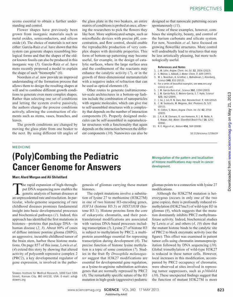
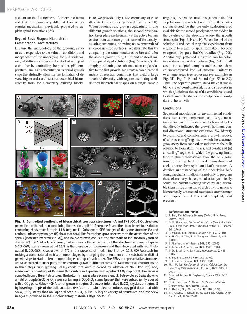
Beyond Basic Shapes: HierarchicalCombinatorial ArchitecturesBecause the morphology of the growing struc-tures is responsive to the solution conditions andindependent of the underlying form, a wide va-riety of different shapes can be stacked on top ofeach other by controlling the position, pH, tem-perature, and salt concentration in serial growthsteps that distinctly allow for the formation of di-verse higher-order architectures assembled hierar-chically from the elementary building blocks.
Here, we provide only a few exemplary cases toillustrate the concept (Fig. 5 and figs. S6 to S8).When structures are grown sequentially in twodifferent growth solutions, the second precipita-tion takes place preferentially at the active bariumor strontium carbonate growth sites of the already-existing structures, showing no overgrowth ofsilica-passivated surfaces. We illustrate this bycomparing the same structures before and afterthe second growth using SEM and confocal mi-croscopy of dyed solutions (Fig. 5, A to C). Bysimply positioning the substrate at an angle rela-tive to the first growth, we create a combinatorialmatrix of reaction conditions that yield a largestructural diversity with regions exhibiting well-defined hierarchical shapes on a single sample
(Fig. 5D). When the structures grown in the firststep become overcoated with SiO2, these sitesare passivated, so that the only nucleation sitesavailable for the second precipitation are hidden inthe cavities of the structure where the growthfronts split (Fig. 5, E and F). When the pH of thesolution is reduced during the experiment fromregime 2 to regime 3, spiral formations becomeovergrown by pure BaCO3 bundles (Fig. 5G).Additionally, patterned substrates can be selec-tively decorated with structures (Fig. 5H). In allcases, the sculpted complex architectures showan unprecedented level of structural uniformityover large areas (see representative examples inFig. 3D; Fig. 5, E and F; and figs. S6 to S8).Thus, the separate growth steps make it possi-ble to create combinatorial, hybrid structures inwhich a judicious choice of the conditions is usedto stack multiple shapes and sculpt continuouslyduring the growth.
ConclusionsSequential modulations of environmental condi-tions such as pH, temperature, and CO2 concen-tration are used to modify local chemical fieldsthat directly influence the growth front and con-trol directional structure evolution. We identifytwo distinct and complementary growth modes:(i) a “blossoming” regime, in which the structuresgrow away from each other and toward the bulksolution to form stems, vases, and corals; and (ii)a “curling” regime, in which the growing frontstend to shield themselves from the bulk solu-tion by curling back toward themselves andeach other to form spiral and leaf structures. Adetailed understanding of the underlying buf-feringmechanisms allows us not only to programthese elementary shapes, but also to dynamicallysculpt and pattern evolving structures and assem-ble them inside or on top of each other to generatehierarchically assembled multiscale architectureswith unprecedented levels of complexity andprecision.
References and Notes1. P. Ball, The Self-Made Tapestry (Oxford Univ. Press,
Oxford, 1999).2. D. W. Thompson, On Growth and Form (Cambridge Univ.
Press, Cambridge, 1917); abridged edition, J. T. Bonner,Ed. (1961).
3. P. Vukusic, J. R. Sambles, Nature 424, 852 (2003).4. K.-H. Chu, R. Xiao, E. N. Wang, Nat. Mater. 9, 413
(2010).5. J. Aizenberg et al., Science 309, 275 (2005).6. J. K. Gansel et al., Science 325, 1513 (2009).7. J. Ge, J. Lei, R. N. Zare, Nat. Nanotechnol. 7, 428
(2012).8. Z. Bao et al., Nature 446, 172 (2007).9. B. Lim et al., Science 324, 1302 (2009).
10. M. J. Madou, Fundamentals of Microfabrication: TheScience of Miniaturization (CRC Press, Boca Raton, FL,2002).
11. G. M. Whitesides, B. Grzybowski, Science 295, 2418(2002).
12. H. A. Lowenstam, S. Weiner, On Biomineralization(Oxford Univ. Press, Oxford 1989).
13. P. Harting, Q. J. Microsc. Sci. 12, 118 (1872).14. J. J. Pagano, T. Bánsági Jr., O. Steinbock, Angew. Chem.
Int. Ed. 47, 9900 (2008).
Fig. 5. Controlled synthesis of hierarchical complex structures. (A and B) BaCO3-SiO2 structuresgrown first in the solution containing fluorescein at pH 11.2 (regime 2) and then transferred to a solutioncontaining rhodamine B at pH 11.8 (regime 1). Subsequent SEM images of the same structure (A) andconfocal microscopy images (B) show that coral-like formations grow selectively on the active sites of thespirals [indicated by arrows in (A)], and no overgrowth occurs at the side walls of the previously formedshapes. (C) The SEM is false-colored, but represents the actual color of the structure composed of greenSrCO3-SiO2 stems grown at pH 11.8 in the presence of fluorescein and then decorated with red, thick-walled BaCO3-SiO2 vases grown at 4°C in the presence of rhodamine B at pH 11.8. (D) Approach formaking a combinatorial matrix of morphologies by changing the orientation of the substrate in distinctgrowth steps to stack different morphologies on top of each other. The SEMs of representative structuresare false-colored to mark parts of the structure grown in different steps. (E) Multimaterial structure madein three steps: first, growing BaCO3 corals that were thickened by addition of NaCl (top left) and,subsequently, inserting SrCO3 stems (top center) and opening with a pulse of CO2 (top right). The series iscompiled from different structures. The bottom image is a large-area view. (F) False-colored SEMs showinga field of purple SrCO3-SiO2 vases containing SrCO3-SiO2 stems (green) that were subsequently openedwith a CO2 pulse (blue). (G) A spiral grown in regime 2 evolves into naked BaCO3 crystals of regime 3by lowering the pH of the bulk solution. (H) A transmission electron microscopy grid decorated withSrCO3-SiO2 stems that are opened with a CO2 pulse. A larger variety of structures and overviewimages is provided in the supplementary materials (figs. S6 to S8).
17 MAY 2013 VOL 340 SCIENCE www.sciencemag.org836
RESEARCH ARTICLES
on
May
16,
201
3w
ww
.sci
ence
mag
.org
Dow
nloa
ded
from

15. J. H. E. Cartwright, J. M. García-Ruiz, M. L. Novella,F. Otálora, J. Colloid Interface Sci. 256, 351 (2002).
16. C. Ritchie et al., Nat. Chem. 1, 47 (2009).17. S. Mann, Nature 365, 499 (1993).18. S. Mann, G. A. Ozin, Nature 382, 313 (1996).19. G. Falini, S. Albeck, S. Weiner, L. Addadi, Science 271,
67 (1996).20. S. V. Patwardhan, S. J. Clarson, C. C. Perry, Chem.
Commun. 2005, 1113 (2005).21. H. Y. Li, H. L. Xin, D. A. Muller, L. A. Estroff, Science 326,
1244 (2009).22. S.-H. Yu, H. Cölfen, K. Tauer, M. Antonietti, Nat. Mater.
4, 51 (2005).23. L. A. Gower, D. A. Tirrell, J. Cryst. Growth 191, 153 (1998).24. S. D. Sims, J. M. Didymus, S. Mann, J. Chem. Soc. Chem.
Commun. 1995, 1031 (1995).25. J. M. García-Ruiz, E. Melero-García, S. T. Hyde, Science
323, 362 (2009).26. J. M. García-Ruiz, J. L. Amoros, J. Cryst. Growth 55, 379
(1981).27. J. M. García-Ruiz et al., Science 302, 1194 (2003).28. M. Kellermeier et al., Chemistry 18, 2272 (2012).29. T. Terada, S. Yamabi, H. Imai, J. Cryst. Growth 253, 435
(2003).
30. H. C. Berg, E. coli in Motion (Springer, New York,2003).
31. A. M. Turing, Philos. Trans. R. Soc. London Ser. B 237, 37(1952).
32. I. Lengyel, I. R. Epstein, Science 251, 650 (1991).33. G. Ertl, Science 254, 1750 (1991).34. S. Kondo, T. Miura, Science 329, 1616 (2010).35. G. M. Whitesides, R. F. Ismagilov, Science 284, 89 (1999).36. B. A. Grzybowski, Chemistry in Motion (Wiley, Chichester,
2009).37. C. J. Brinker, G. W. Scherer, Sol-Gel Science (Academic
Press, London, 1990).38. W. L. Marshall, J. M. Warakomski, Geochim. Cosmochim.
Acta 44, 915 (1980).39. Our hypothesis suggests that the bulk solution in regime 2
is above the optimum pH for silica formation, whereasin the vicinity of the growth front, the localized acidformation lowers the pH below the optimum level toprecipitate silica on the active growth sites. We confirmedthis localized pH gradient by monitoring BaCO3-SiO2
coprecipitation while deliberately adjusting the bulk pH(see supplementary materials).
40. We assume that the rate of the silica formation is slowenough to enter regime 2 before a layer of silica is formed
that locks the coprecipitation in regime 1. We verified thisassumption by starting from regime 2 and increasing therate of silica precipitation by adding 0.2 mmol NaCl. Asexpected, we observe that the silica nucleation is now fastenough to not enter regime 2, but instead to grow thickenedblossoming structures that correspond to regime 1.
Acknowledgments: We thank J. C. Weaver for advice withthe SEM imaging, S. K. Y. Tang and R. Sadza for themicrofluidic experiments, L. Hendriks for growing thestructures in Fig. 5F, and A. J. Aizenberg for help with themanuscript. This work was supported by the NSF MaterialsResearch Science and Engineering Centers under award no.DMR-0820484. W.L.N. thanks the Netherlands Organizationfor Scientific Research for financial support. EM was performedat Harvard’s Center for Nanoscale Systems, supported by theNSF under award no. ECS-0335765.
Supplementary Materialswww.sciencemag.org/cgi/content/full/340/6134/832/DC1Materials and MethodsFigs. S1 to S8
28 December 2012; accepted 19 March 201310.1126/science.1234621
Dual Molecular Signals Mediatethe Bacterial Response toOuter-Membrane StressSantiago Lima,1* Monica S. Guo,2* Rachna Chaba,3† Carol A. Gross,3,4 Robert T. Sauer1‡
In Gram-negative bacteria, outer-membrane integrity is essential for survival and is monitored bythe sE stress-response system, which initiates damage-repair pathways. One activating signal isunassembled outer-membrane proteins. Using biochemical and genetic experiments in Escherichia coli,we found that off-pathway intermediates in lipopolysaccharide transport and assembly provided anadditional required signal. These distinct signals, arising from disruptions in the transport and assemblyof the major outer-membrane components, jointly determined the rate of proteolytic destruction of anegative regulator of the sE transcription factor, thereby modulating the expression of stress-responsegenes. This dual-signal system permits a rapid response to dysfunction in outer-membrane biogenesis,while buffering responses to transient fluctuations in individual components, and may represent abroad strategy for bacteria to monitor their interface with the environment.
The outer membrane (OM) is essential forthe survival of Gram-negative bacteria. InEscherichia coli, the sE stress-response sys-
tem recognizes signals indicative of OM dys-function and triggers an adaptive response byactivating the expression of gene products in-
volved in the biogenesis, transport, and/or assemblyof the lipopolysaccharides (LPSs), phospholipids,and outer-membrane proteins (OMPs) that makeup theOM, and the proteases and chaperones thatmaintain or repair OM integrity (1, 2). In thissystem, the RseA and RseB regulatory proteinsand the DegS and RseP inner-membrane (IM)proteases transmit the signal that activates the sE
transcription factor (fig. S1). RseA, a single-passIM protein, has a cytoplasmic domain that bindsand inhibits sE and a periplasmic domain (RseAP)that binds RseB (3–5). After stress, OMPs accu-mulate in the periplasm, and their C-terminal
1Department of Biology, Massachusetts Institute of Technology,Cambridge, MA 02139, USA. 2Department of Biochemistry andBiophysics, University of California, San Francisco, CA 94158,USA. 3Department of Microbiology and Immunology, Uni-versity of California, San Francisco, CA 94158, USA. 4Depart-ment of Cell and Tissue Biology, University of California, SanFrancisco, CA 94158, USA.
*These authors contributed equally to this work.†Present address: Indian Institute of Science Education andResearch–Mohali, Sector 81, Knowledge City, S.A.S Nagar,Punjab 140306, India.‡Corresponding author. E-mail: [email protected]
[LptA protein] (µM)
C
45 °C
35 °C
25 °C
300 µM LPS rela
tive
inhi
bitio
n of
R
seB
elu
tion
(%)
0
20
40
60
80
100
0 40 80 120
A
0
20
40
60
80
100
RseB
RseA
BSA
lysoz
yme
PG
35S
-Rse
B e
lute
d (%
)
buffe
r
buffe
r, 45
°
B
35S
-Rse
B e
lute
d (%
)
[LPS] (µM)
0
10
20
30
40
50
0 200 400 600 800
PO4PO4
D
GlcNAC GlcNAC
Glc
Hep Hep
Glc Gal
Glc
Kdo Kdo
Hep
outercore
sugars
Hep
innercore
sugars
lipid A acylchains
Kdo2-lipid A
Fig. 1. LPS displacesRseA fromRseB. (A) RseB (35 mM) and RseAP (100 mM)eluted 35S-RseB (~1 mM) from RseAP-agarose, whereas buffer controls, bovine serum al-bumin, (BSA, 125mM), lysozyme (125mM), or phosphatidylglycerol (PG, 13mM)didnot. (B) LPS fromE. coliK12eluted 35S-RseB fromRseAP-agarose (25°C). Data (meanT
SD,n=3 independent replicates) were fit to ahyperbolic function (Kapp =270mM). (C)LptA inhibition of RseB elution by LPS (300 mM) was more efficient at lower tem-peratures. (D) Structure of E. coli K12 LPS (Kdo, keto-deoxyoctulosonate; Hep, heptose;Gal, galactose; Glc, glucose). The dark gray elements mediate RseB binding.
www.sciencemag.org SCIENCE VOL 340 17 MAY 2013 837
RESEARCH ARTICLES
on
May
16,
201
3w
ww
.sci
ence
mag
.org
Dow
nloa
ded
from