compensation of voltage variations in …ieejournal.com/vol_4_no_1/compensation of voltage...
TRANSCRIPT
International Electrical Engineering Journal (IEEJ) Vol. 4 (2013) No. 1, pp. 1017-1026 ISSN 2078-2365
1017
COMPENSATION OF VOLTAGE VARIATIONS IN DISTRIBUTION SYSTEM BY USING DVR BASED SEPARATE ENERGY STORAGE DEVICES
COMPENSATION OF VOLTAGE VARIATIONS IN
DISTRIBUTION SYSTEM BY USING DVR BASED SEPARATE
ENERGY STORAGE DEVICES
R.Vijayakumar1, R.Subramanian
2
1 Department of Electrical and Electronics Engg, SNS College of Technology, Coimbatore 2 Department of Electrical and Electronics Engg, SNS College of Technology, Coimbatore
Abstract— The Separate Energy Storage Device
(SESD) based Dynamic Voltage Restorer (DVR) used
to protect consumers from the grid voltage
fluctuations like Long and Short-Duration Voltage
Variations. This paper analyses the operation
principle of the SESD based DVR and its design is
based on simple PI control method and decision
making switch to compensate Long and Short-
Duration Voltage Variations. During short-duration
voltage variation super capacitor and fuel cell hybrid
system is used to compensate the fault. In the same
way during long-duration voltage variation
photovoltaic (PV) system or backup battery or other
grid is used to compensate the fault based on the
availability. Using MATLAB/SIMULINK, the models
of the SESD based DVR is establish, and the
simulation tests are performed to evaluate the system
performances.
Keywords- DVR; Long and Short-Duration Voltage
Variations; Pulse-width modulated (PWM); Decision
making switch; Grid; Bidirectional Isolated DC–DC
Converter, SESD.
I. INTRODUCTION
Power systems have been experiencing good
changes in electric power generations, transmissions,
and distributions. For electrical load growth and higher
power transfer in a largely interconnected network lead to complex and less secure power system operation. Power
system engineers facing challenges seek solutions to
operate the system in more a flexible and controllable manner. So role of energy storage devices play important
role as Energy storage appears to be beneficial to utilities
since it can decouple the instantaneous balancing between
supply and demand. Therefore increased asset utilization is allowed, that facilitates the renewable sources penetration
and improves the flexibility, reliability and efficiency of
the grid long and short-duration voltage
Variations by abrupt increases in loads such as faults or short circuits, starting of motors, or turning on of
electric heaters or they are caused by abrupt source
impedances is increase, which are caused by a loose
connection. Power quality issues are divided into two categories voltage quality and frequency quality. Voltage
quality issues are related with voltage sag, voltage swell,
under voltage and over voltage while frequency quality issues are related with harmonics and transients. One of
International Electrical Engineering Journal (IEEJ) Vol. 4 (2013) No. 1, pp. 1017-1026 ISSN 2078-2365
1018
COMPENSATION OF VOLTAGE VARIATIONS IN DISTRIBUTION SYSTEM BY USING DVR BASED SEPARATE ENERGY STORAGE DEVICES
the most imperative power quality issues is voltage sag
which is occur due to its usage of voltage sensitive devices.
Energy storage devices can be classified into two diff
categories, depending upon their application: short term response energy storage devices and long-term response
energy storage devices. Short term response energy
devices which include flywheel, super capacitor, SMES
whereas long term response energy storage devices include compress air, hydrogen fuel cell, batteries, Redox
flow. Here we are more concern with short term response
energy devices. For Long and Short-Duration Voltage Variations
compensation, the DVR which acts as series-connected
topology is a more cost-effective solution. In this paper, a SESD unit is introduced as the energy storage unit of the
DVR. Application of SESD for power conditioning with
DVR is put forth. The dynamic response of the SESD
based DVR on voltage sag and swell is evaluated using MATLAB simulation.
The energy storage devices are split in to two
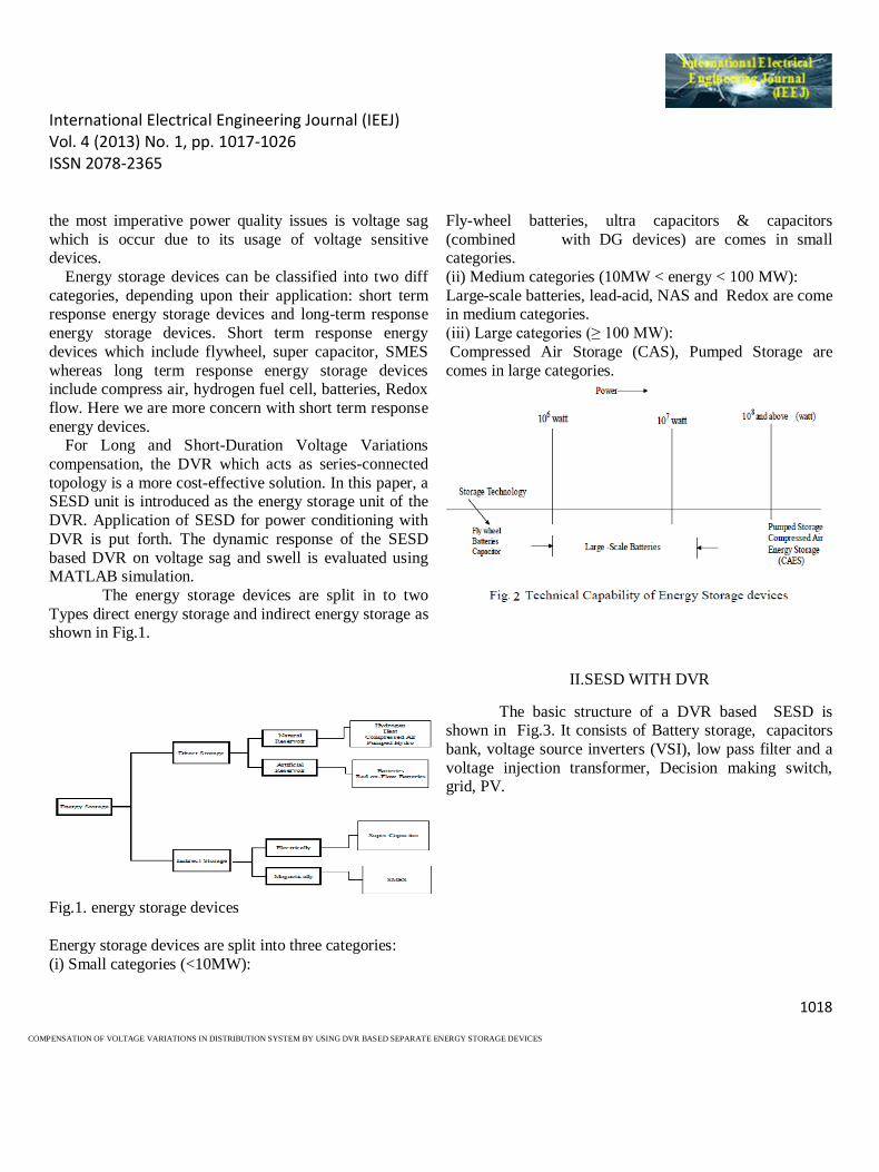
Types direct energy storage and indirect energy storage as shown in Fig.1.
Fig.1. energy storage devices
Energy storage devices are split into three categories:
(i) Small categories (<10MW):
Fly-wheel batteries, ultra capacitors & capacitors
(combined with DG devices) are comes in small categories.
(ii) Medium categories (10MW < energy < 100 MW):
Large-scale batteries, lead-acid, NAS and Redox are come in medium categories.
(iii) Large categories (≥ 100 MW):
Compressed Air Storage (CAS), Pumped Storage are
comes in large categories.
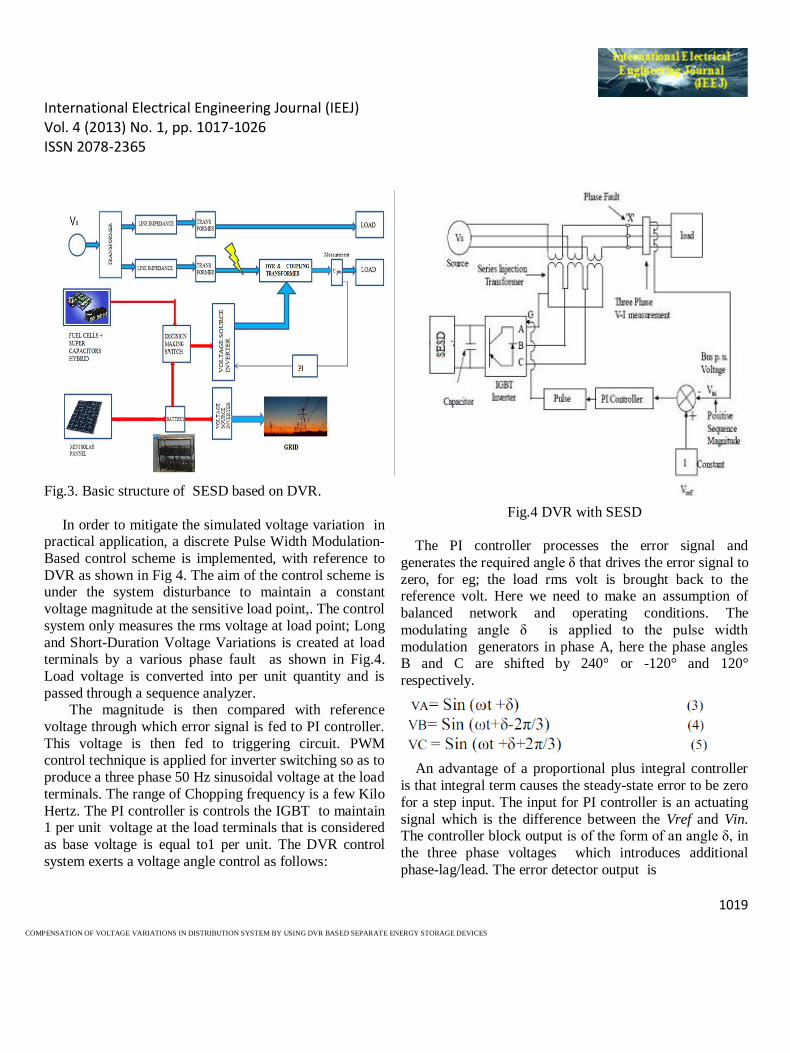
II.SESD WITH DVR
The basic structure of a DVR based SESD is shown in Fig.3. It consists of Battery storage, capacitors
bank, voltage source inverters (VSI), low pass filter and a
voltage injection transformer, Decision making switch, grid, PV.
International Electrical Engineering Journal (IEEJ) Vol. 4 (2013) No. 1, pp. 1017-1026 ISSN 2078-2365
1019
COMPENSATION OF VOLTAGE VARIATIONS IN DISTRIBUTION SYSTEM BY USING DVR BASED SEPARATE ENERGY STORAGE DEVICES
Fig.3. Basic structure of SESD based on DVR.
In order to mitigate the simulated voltage variation in practical application, a discrete Pulse Width Modulation-
Based control scheme is implemented, with reference to
DVR as shown in Fig 4. The aim of the control scheme is under the system disturbance to maintain a constant
voltage magnitude at the sensitive load point,. The control
system only measures the rms voltage at load point; Long
and Short-Duration Voltage Variations is created at load terminals by a various phase fault as shown in Fig.4.
Load voltage is converted into per unit quantity and is
passed through a sequence analyzer. The magnitude is then compared with reference
voltage through which error signal is fed to PI controller.
This voltage is then fed to triggering circuit. PWM control technique is applied for inverter switching so as to
produce a three phase 50 Hz sinusoidal voltage at the load
terminals. The range of Chopping frequency is a few Kilo
Hertz. The PI controller is controls the IGBT to maintain 1 per unit voltage at the load terminals that is considered
as base voltage is equal to1 per unit. The DVR control
system exerts a voltage angle control as follows:
Fig.4 DVR with SESD
The PI controller processes the error signal and
generates the required angle δ that drives the error signal to
zero, for eg; the load rms volt is brought back to the reference volt. Here we need to make an assumption of
balanced network and operating conditions. The
modulating angle δ is applied to the pulse width
modulation generators in phase A, here the phase angles B and C are shifted by 240° or -120° and 120°
respectively.
An advantage of a proportional plus integral controller
is that integral term causes the steady-state error to be zero
for a step input. The input for PI controller is an actuating
signal which is the difference between the Vref and Vin. The controller block output is of the form of an angle δ, in
the three phase voltages which introduces additional
phase-lag/lead. The error detector output is
International Electrical Engineering Journal (IEEJ) Vol. 4 (2013) No. 1, pp. 1017-1026 ISSN 2078-2365
1020
COMPENSATION OF VOLTAGE VARIATIONS IN DISTRIBUTION SYSTEM BY USING DVR BASED SEPARATE ENERGY STORAGE DEVICES
Vref equal to 1 p.u. voltage
Vin voltage in p.u. at the load terminals.
The controller output when compare at PWM signal generator results in the desired firing sequence.
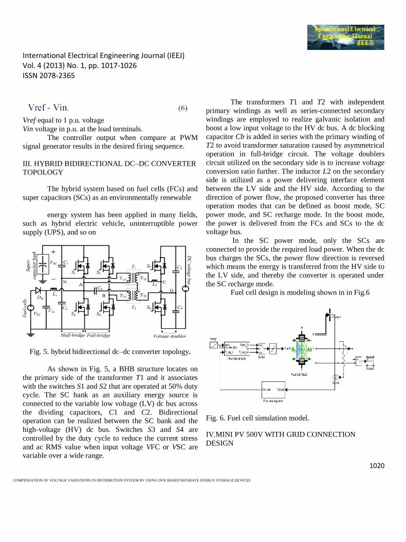
III. HYBRID BIDIRECTIONAL DC–DC CONVERTER
TOPOLOGY
The hybrid system based on fuel cells (FCs) and
super capacitors (SCs) as an environmentally renewable
energy system has been applied in many fields,
such as hybrid electric vehicle, uninterruptible power
supply (UPS), and so on
Fig. 5. hybrid bidirectional dc–dc converter topology.
As shown in Fig. 5, a BHB structure locates on
the primary side of the transformer T1 and it associates
with the switches S1 and S2 that are operated at 50% duty cycle. The SC bank as an auxiliary energy source is
connected to the variable low voltage (LV) dc bus across
the dividing capacitors, C1 and C2. Bidirectional operation can be realized between the SC bank and the
high-voltage (HV) dc bus. Switches S3 and S4 are
controlled by the duty cycle to reduce the current stress
and ac RMS value when input voltage VFC or VSC are variable over a wide range.
The transformers T1 and T2 with independent
primary windings as well as series-connected secondary windings are employed to realize galvanic isolation and
boost a low input voltage to the HV dc bus. A dc blocking
capacitor Cb is added in series with the primary winding of T2 to avoid transformer saturation caused by asymmetrical
operation in full-bridge circuit. The voltage doublers
circuit utilized on the secondary side is to increase voltage
conversion ratio further. The inductor L2 on the secondary side is utilized as a power delivering interface element
between the LV side and the HV side. According to the
direction of power flow, the proposed converter has three operation modes that can be defined as boost mode, SC
power mode, and SC recharge mode. In the boost mode,
the power is delivered from the FCs and SCs to the dc voltage bus.
In the SC power mode, only the SCs are
connected to provide the required load power. When the dc
bus charges the SCs, the power flow direction is reversed which means the energy is transferred from the HV side to
the LV side, and thereby the converter is operated under
the SC recharge mode. Fuel cell design is modeling shown in in Fig.6
Fig. 6. Fuel cell simulation model.
IV.MINI PV 500V WITH GRID CONNECTION
DESIGN
International Electrical Engineering Journal (IEEJ) Vol. 4 (2013) No. 1, pp. 1017-1026 ISSN 2078-2365
1021
COMPENSATION OF VOLTAGE VARIATIONS IN DISTRIBUTION SYSTEM BY USING DVR BASED SEPARATE ENERGY STORAGE DEVICES
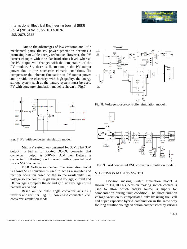
Due to the advantages of low emission and little
mechanical parts, the PV power generation becomes a promising renewable energy technique. However, the PV
current changes with the solar irradiations level, whereas
the PV output volt changes with the temperature of the PV module. So, there is fluctuation in the PV output
power due to the stochastic climatic conditions. To
compensate the inherent fluctuation of PV output power
and provide the electricity with high quality, the energy storage system such as the battery system must be used.
PV with converter simulation model is shown in Fig.7.
Fig. 7. PV with converter simulation model.
Mini PV system was designed for 30V. That 30V
output is fed in to isolated DC-DC converter that
converter output is 500Vdc. And then Battery is connected to floating condition and with connected grid
by via VSC converter.
Fig.8. Voltage source controller simulation model is shown.VSC converter is used to act as a inverter and
rectifier operation based on the source availability. For
voltage source controller get the grid voltage, current and
DC voltage. Compare the dc and grid side voltages pulse patterns are varied.
Based on the pulse angle converter acts as a
inverter and rectifier. Fig. 9. Shows Grid connected VSC converter simulation model
Fig. 8. Voltage source controller simulation model.
Fig. 9. Grid connected VSC converter simulation model.
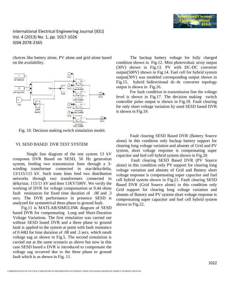
V. DECISION MAKING SWITCH
Decision making switch simulation model is
shown in Fig.10.This decision making switch control is
used to allow which energy source is supply for compensation during fault condition. The short duration
voltage variation is compensated only by using fuel cell
and super capacitor hybrid combination in the same way for long duration voltage variation compensated by various
International Electrical Engineering Journal (IEEJ) Vol. 4 (2013) No. 1, pp. 1017-1026 ISSN 2078-2365
1022
COMPENSATION OF VOLTAGE VARIATIONS IN DISTRIBUTION SYSTEM BY USING DVR BASED SEPARATE ENERGY STORAGE DEVICES
choices like battery alone, PV alone and grid alone based
on the availability.
Fig. 10. Decision making switch simulation model.
VI. SESD BASED DVR TEST SYSTEM
Single line diagram of the test system 13 kV
composes DVR Based on SESD, 50 Hz generation
system, feeding two transmission lines through a 3- winding transformer connected in star/delta/delta,
13/115/115 kV. Such trans lines feed two distribution
networks through two transformers connected in
delta/star, 115/11 kV and then 11KV/500V. We verify the working of DVR for voltage compensation at 0.44 ohms
fault resistances for fixed time duration of .08 and .3
secs. The DVR performance in presence SESD is analyzed for symmetrical three phase to ground fault.
Fig.11 is MATLAB/SIMULINK diagram of SESD
based DVR for compensating Long and Short-Duration
Voltage Variations. The first simulation was carried out without SESD based DVR and a three phase to ground
fault is applied to the system at point with fault resistance
of 0.44Ω for time duration of .08 and .3 secs. which result voltage sag as shown in Fig.5. The second simulation is
carried out at the same scenario as above but now in this
case SESD based a DVR is introduced to compensate the voltage sag occurred due to the three phase to ground
fault which is as shown in Fig. 11.
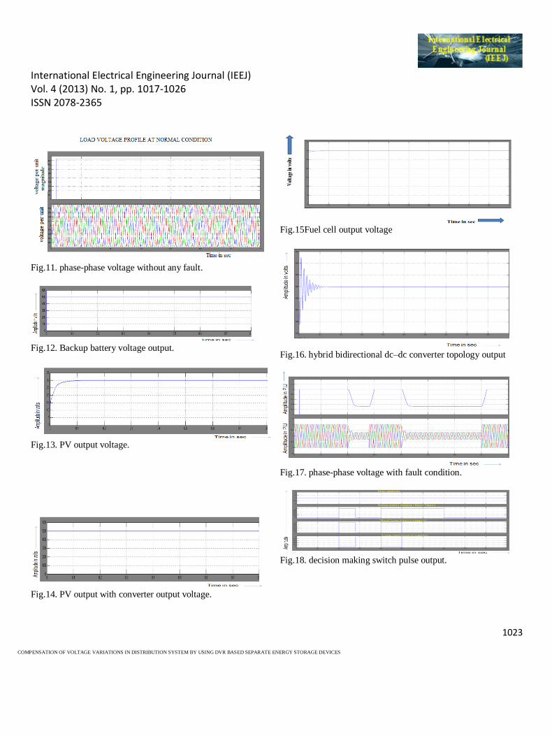
The backup battery voltage for fully charged
condition shown in Fig.12. Mini photovoltaic array output (30V) shown in Fig.13. PV with DC-DC converter
output(500V) shown in Fig.14. Fuel cell for hybrid system
output(30V) was modeled corresponding output shown in Fig.15. hybrid bidirectional dc–dc converter topology
output is shown in Fig.16.
For fault condition in transmission line the voltage
level is shown in Fig.17. The decision making switch controller pulse output is shown in Fig.18. Fault clearing
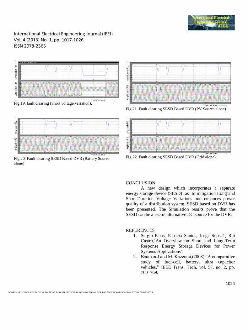
for only short voltage variation by used SESD based DVR
is shown in Fig.19.
Fault clearing SESD Based DVR (Battery Source
alone) in this condition only backup battery support for
clearing long voltage variation and absents of Grid and PV system, short voltage response is compensating super
capacitor and fuel cell hybrid system shown in Fig.20.
Fault clearing SESD Based DVR (PV Source alone) in this condition only PV support for clearing long
voltage variation and absents of Grid and Battery short
voltage response is compensating super capacitor and fuel cell hybrid system shown in Fig.21. Fault clearing SESD
Based DVR (Grid Source alone) in this condition only
Grid support for clearing long voltage variation and
absents of Battery and PV system short voltage response is compensating super capacitor and fuel cell hybrid system
shown in Fig.22.
International Electrical Engineering Journal (IEEJ) Vol. 4 (2013) No. 1, pp. 1017-1026 ISSN 2078-2365
1023
COMPENSATION OF VOLTAGE VARIATIONS IN DISTRIBUTION SYSTEM BY USING DVR BASED SEPARATE ENERGY STORAGE DEVICES
Fig.11. phase-phase voltage without any fault.
Fig.12. Backup battery voltage output.
Fig.13. PV output voltage.
Fig.14. PV output with converter output voltage.
Fig.15Fuel cell output voltage
Fig.16. hybrid bidirectional dc–dc converter topology output
Fig.17. phase-phase voltage with fault condition.
Fig.18. decision making switch pulse output.
International Electrical Engineering Journal (IEEJ) Vol. 4 (2013) No. 1, pp. 1017-1026 ISSN 2078-2365
1024
COMPENSATION OF VOLTAGE VARIATIONS IN DISTRIBUTION SYSTEM BY USING DVR BASED SEPARATE ENERGY STORAGE DEVICES
Fig.19. fault clearing (Short voltage variation).
Fig.20. Fault clearing SESD Based DVR (Battery Source
alone)
Fig.21. Fault clearing SESD Based DVR (PV Source alone)
Fig.22. Fault clearing SESD Based DVR (Grid alone).
CONCLUSION
A new design which incorporates a separate
energy storage device (SESD) as to mitigation Long and
Short-Duration Voltage Variations and enhances power quality of a distribution system. SESD based on DVR has
been presented. The Simulation results prove that the
SESD can be a useful alternative DC source for the DVR.
REFERENCES
1. Sergio Faias, Patricia Santos, Jorge Sousa1, Rui Castro,’An Overview on Short and Long-Term
Response Energy Storage Devices for Power
Systems Applications’. 2. Bauman.J and M. Kazerani,(2008) ―A comparative
study of fuel-cell, battery, ultra capacitor
vehicles,‖ IEEE Trans, Tech, vol. 57, no. 2, pp. 760–769.
International Electrical Engineering Journal (IEEJ) Vol. 4 (2013) No. 1, pp. 1017-1026 ISSN 2078-2365
1025
COMPENSATION OF VOLTAGE VARIATIONS IN DISTRIBUTION SYSTEM BY USING DVR BASED SEPARATE ENERGY STORAGE DEVICES
3. Chen,Y.M Y.-C. Liu, and F.-Y. Wu,(2002)
―Multi-input DC-DC converter based on the multi winding transformer for renewable energy
application.
4. Jin,.K X. Ruan, M. Yang, and M. Xu, (2007)―Power management for fuel-cell power
system start‖ IEEE Transaction, Electronics.,
vol. 24, 5. Liu.D and H. Li, (2006)―A ZVS bi-directional
DC–DC converter for multiple energy storage
elements,‖ IEEE Trans. Power Electron., vol. 21,no. 5,pP1513–1517,
6. Liu D.C D.D.Cand V. G. Agelidis,
(2009)―Photovoltaic-battery-powered DC bus system for common portable elect devices‖ IEEE
Trans, Power Electronic., vol. 24, no, 3, pp. 849–855
7. Peng, F.Z H. Li, G. J. Su, and J. S. Lawler,
(2004)―A new ZVS bi directional DC–DC converter for fuel cell and battery application,”
IEEE Transe. Power Electron., vol. 19, no. 1, pp.
54–65 8. Payman A, S. Pierfederici, and F. Meibody-
Tabar,(2009) ―Energy management in a fuel
cell/supercapacitor multisource/multiload electrical hybrid system,.‖ IEEE Trans. Power
Electron., vol. 24, no. 12,
9. Qian.z Abdel-Rahman, H. Al-Atrash, and I. Batarseh,(2010) ―Modeling and control of three-
port DC/DC converter interface,‖ IEEE Trans.
Power Electron., vol. 25, no. 3, pp. 637–649 10. Fang Y. and X. Ma, ―A novel PV micro-inverter
with coupled inductors and doubles boost
topology.,‖ IEEE Trans. Power Electron., vol. PP, no. 99,p. 1, 2010.
11. Solar Edge System Overview. (Jan. 2011).
[Online].Available:http://www.solaredge.com/files/pdfs/se_system_overview.pdf
12. B, Ferdi, S. Dib, R.Dehini University of Bachar,
Algeria, ―.Adaptive PI Control of DVR Using
FUZZY Logic,‖ Journal of Electrical Engineering
:Theory and Application Vol. 1, pp. 165-173, 2010.
13. C.Sankaran‖Power quality‖, CRC Press 2002
14. D. Daniel Sabin, Senior Member, IEEE, and Ambra Sannino, IEEE ―A Summary of the Draft
IEEE P1409 Custom Power Application
Guide‖Transmission and Distribution Conference and Exposition,IEEE PES, vol. 3,pp.931-936,2003
15. Fawzi AL Jowder ―Modeling and Simulation of
Different System Topologies For Dynamic Voltage Restorer‖ Electric Power and Energy
Conversion Systems, EPECS ’09. International
Conference , IEEE, pp. 1-6, 2009. 16. G. Yalcinkaya, M.J.H Bollen, P.A Crossley,
―characterization of voltage sags in industrial distri
system‖, IEEE transaction on industrial applications, vol.34, pp. 682-688 july-aug, 1998
17. H.A. Peterson, N. Mohan, R. W. Boom,
―Superconductive Energy Storage Inductor Converter Units for Power, Systems,‖ IEEE
Transaction on Power Apparatus and Systems.,
vol. PAS-94, no.4, p.1337-1347, July/August 75. 18. H.P. Tiwari, Sunil Kumar Gupta, Ramesh Pachar
―Study of Major Issues and Their Impact on DVR
System Performance‖ International Journal of
Computer and Electrical Engineering, Vol. 2, No. 1, February, 10.
19. H.P.Tiwari and Sunil Kumar Gupta ―Dynamic
Voltage Restorer against Voltage Sag‖ International Journal of Innovation., management
and Tech vol. 1, no.3, pp., 232-237, 10.
20. John Godsk Nielsen and Frede Blaabjerg ―Control Strategies for Dynamic Voltage Restorer
International Electrical Engineering Journal (IEEJ) Vol. 4 (2013) No. 1, pp. 1017-1026 ISSN 2078-2365
1026
COMPENSATION OF VOLTAGE VARIATIONS IN DISTRIBUTION SYSTEM BY USING DVR BASED SEPARATE ENERGY STORAGE DEVICES
Compensating Voltage Sags with Phase
Jump,‖,Applied Power Electronic Conference and Exposition,IEEE, vol, 2, pp. 1267-1273,2001
21. K.R. Padiyar ―Facts controllers in power
transmission and distribution‖ new age international (P) Ltd publisher, 07.
22. M. H. Hque, ―Compensation of Distribution
System Voltages Sag by DVR and D
STATCOM‖, IEEE Power Tech Conference, volume. 1, 02.