comparison of oxy-sulfide alloy tablets and ca-bearing ... · the benefits of late in-mold...
TRANSCRIPT

Comparison of Oxy-sulfide Alloy Tablets and Ca-bearing FeSi75 for Late Inoculation of Low Sulfur Grey Irons
M. Chisamera, I. Riposan, S. Stan, C.B. Albu, C. Brezeanu
POLITEHNICA University of Bucharest, Bucharest, Romania
R. L. Naro ASI INTERNATIONAL, LTD, Cleveland, Ohio, USA
Copyright 2007 American Foundry Society ABSTRACT Inoculation comparisons were made between calcium-bearing, foundry-grade 75% ferrosilicon (FeSi75) and a proprietary complex alloy tablet (hereafter referred to as CAT) to determine their effects on late inoculation. In-mold addition rates for FeSi75 ranged from 0.1% to 0.3%; the complex alloy tablets, based on oxy-sulfide chemistry, were added in much smaller amounts, 0.01% to 0.03%. In-mold inoculation was used simultaneously at three inoculant levels in multi-cavity test molds to evaluate chill tendency, microstructure and Brinell hardness characteristics. Thermal analysis also was used to study the solidification behavior of the base iron and the effect of FeSi75 and the complex alloy tablet inoculants on graphite nucleation. Thermal analysis of the base low-sulfur iron was characterized by excessive eutectic undercooling. It was found that an addition of 0.03% CAT had an inoculation efficiency comparable with 0.2% to 0.3% calcium-bearing foundry-grade FeSi75. CAT addition rates of less than 0.05% (based on the test casting weight) were extremely effective for late inoculation of grey irons. Irons inoculated with the CAT were less likely to chill (inclusively as inverse chill) and to develop micro-shrinkage formations, compared with calcium-bearing FeSi75 treatments. The CAT inoculant can be used at significantly reduced addition levels. INTRODUCTION The benefits of late in-mold inoculation for both grey and ductile irons are well known to foundrymen. Late in-mold additions are often utilized as a secondary inoculant to prevent under-inoculation from insufficient ladle additions, fade, or malfunctions of in-stream inoculation injectors or feeders. By inoculating at the last possible instance, control over microstructure and hardness values are easily achieved and inoculant fade is eliminated. Late inoculation eliminates the need to super-inoculate to compensate for fading and allows for improved control of silicon levels. Further, with the continued emphasis and growth of automatic mold pouring, difficulties associated with consistent stream inoculation are minimized. Lastly, whether in-mold inoculation is being used as the primary mode of inoculation or as a secondary booster addition, overall inoculant addition rates for a given casting weight can be reduced. Over the years, numerous methods have been developed for inoculating in the mold. These include adding loose granular inoculants directly to the sprue well, the anchoring of solid cast inserts, typically made from a calcium and aluminum containing FeSi75 alloy, or pressed composites of ferrosilicon based alloys, in prints located in the gating system or positioned at a ceramic filter. Some foundries even use hand-selected lumps of calcium bearing FeSi75 placed in the gating system, but usually before a ceramic filter. Becker1 showed that a fine sized, granulated proprietary oxy-sulfide containing inoculant, placed in a reaction reservoir or basin in the gating system and near the downsprue, could replace a similar weight of cast inoculant inserts. Becker also described how one foundry totally replaced ladle inoculation with in-mold inoculation using fine sized, granulated inoculants, placed in a reaction basin in the gating system. Becker also stressed that the use of ceramic filters was necessary to prevent un-dissolved inoculant defects. Regardless of whether the in-mold inoculant is in the form of a cast insert, a pressed tablet such as the CAT inoculant, or in the form of a granulated oxy-sulfide containing CAT-type inoculant, the submerged reaction occurs within the confines of a green sand or chemically bonded mold that generally provides a reducing atmosphere. By eliminating exposure to the atmosphere, as occurs with stream inoculation, the use of highly effective, reactive elements that readily form oxy-sulfide nuclei for graphite precipitation is possible.

It has been postulated that the effectiveness of ferrosilicon-based alloys formulated as cast iron inoculants is dependent upon the presence of minor amounts of the elements calcium, aluminum, barium, strontium, and—to a lesser degree—rare earths, zirconium and titanium. Late ladle additions of either commercially pure silicon metal or high-purity ferrosilicon can do little, if anything, to modify the microstructural and mechanical properties of grey iron2-5. Many studies have found both calcium and aluminum to be essential components of ferrosilicon-based inoculants. Complex (Mn,X)S compounds (where X = Fe, Al, O, Ca, Si, Sr, Ti, Zr, etc.) nucleated on Al2O3-based sites and were the primary sites for graphite flake growth in both un-inoculated and inoculated grey irons. Other important elements such as calcium and strontium were found to distribute differently in the inclusion volume: calcium was distributed evenly throughout the inclusion; strontium was found mainly in the core of the inclusions. Particles associated with graphite had a lower Mn/S ratio than the matrix-embedded particles, and Ca-FeSi and Sr-FeSi inoculated irons had a lower Mn/S ratio than high-purity (HP) FeSi treated irons3,4-7. Oxy-sulfide forming elements appear to have a very important role in graphite nucleation in cast irons. To exploit the important role that sulfur and oxygen play in the nucleation of graphite, a new complex alloy has recently been developed8. The new CAT, which is available in either tablet or briquette form, contains potent nuclei (or oxy-sulfide) forming elements in a concentrated, easy-to-use form. For in-stream or ladle inoculation, the product is available in a traditional granular form. In either form, they contain up to 20 times the level of oxy-sulfide forming elements normally found in other ladle inoculants, in-stream inoculants, or cast and/or sintered inserts9. The use of sulfur with inoculating agents is not a new concept. The simultaneous addition of sulfur with potent oxy-sulfide forming elements was first demonstrated by Naro and Wallace10,11. Naro showed that balanced ratios of rare earths and sulfur, without the presence of ferrosilicon, drastically reduced undercooling, completely eliminated chill and promoted favorable graphite shapes in grey irons. Strande12 showed that using CaSi-based inoculants along with increased direct sulfur additions to the metal vastly improved machinability in gray iron castings compared with proprietary Sr-FeSi based inoculants and similar sulfur additions. Chisamera13 also illustrated the importance of sulfur content and inoculant effectiveness in grey irons. In ductile irons, Riposan and Chisamera13-15 demonstrated that a small sulfur addition (less than 0.01%), when added concurrently with CaSi-based inoculants, increased graphite-nucleation potential in ductile iron without affecting graphite nodularity. In related research, Chisamera and Riposan16 showed that the strong sulfide-forming tendencies of calcium and rare earths, when used with controlled sulfur additions, strongly promoted the formation of sulfide compounds, assisting in their effectiveness as nodular graphite nuclei. Later, Skaland17,18 developed an inoculant concept based on adding small and controlled amounts of sulfur and oxygen in a specific form that would react with calcium and cerium when introduced into liquid iron. The current experimental investigation in this paper was designed to evaluate the nucleation power and effectiveness of a newly developed oxy-sulfide CAT at very low addition levels. The inoculation performance and effectiveness of the proprietary tablets were compared with a typical foundry-grade Ca-bearing FeSi75 as a conventional, in-mold inoculant. EXPERIMENTAL PROCEDURE To ensure a low level of trace elements, a relatively pure charge consisting of clean steel scrap, sand-blasted foundry returns, a low-sulfur re-carburizer and ferroalloys was used in the experiment. Pig iron was purposely excluded from the charge so that the base iron would be less responsive to inoculation. Typical chemistry of the base iron was 3.40% carbon, 1.70% silicon, 0.75% manganese, 0.02% sulfur and 0.12% phosphorous; this resulted in an approximately 3.90% carbon-equivalent level. The charge was melted in a 100 kg, 2400 Hz frequency, 100 kW, silica-lined coreless induction furnace. Experimental heats were superheated to 1500oC (2732oF) and were poured into test castings made from furan no-bake bonded molds. The test castings all were poured at 1450oC (2642oF). Pouring time for each test casting was approximately 5 seconds. The specially designed test mold included a central downsprue, which simultaneously supplied un-inoculated grey iron to three separate test reaction chambers. An American Society for Testing Materials (ASTM A367 specification, W3½ chill wedge having a 25 mm base width, 44 mm high, 144 mm long) and a round bar specimen (20 mm diameter, 150 mm high) were gated off the inoculation reaction chamber. Figure 1 illustrates the casting configuration used for the experiments. As molten iron flows into each of the three reaction chambers, inoculation occurs and the inoculated iron then flows into the chill wedge and round test bars. The combined weight of each reaction chamber, ingates, chill wedge and round test bar was 0.92 kg (2.024 lbs); the entire test casting weighed 3.21 kg (7.062 lbs).

25
44
Ф20
Ф20 25
44
25
Ф2044
25 Ф20
25
25
2
1
6
4
3 5
Fig. 1. Detail of in-mold inoculation pattern (three work positions): 1 – down sprue; 2 – reaction chamber;3 –runner; 4 – gates; 5 – wedge sample (W31/2 – ASTM – A367); 6 – cylindrical bar (Ф20 x 150 mm)
The proprietary CAT was employed at 0.01%, 0.02% and 0.03% levels in the in-mold reaction chamber; the calcium-bearing FeSi75 was utilized at 0.1%, 0.2% and 0.3%. A highly accurate analytical balance was used to evaluate each addition rate. After casting, the chill wedges and bars were allowed to cool to room temperature before they were shaken out. A careful examination of the exterior test wedge and bar surfaces was made to ensure that the castings were free from any in-mold surface or slag reactions. The composition of the proprietary oxy-sulfide inoculant tablet and the foundry-grade calcium-bearing FeSi75 is shown in Table 1.
Table 1. Inoculant Chemistry and Characteristics
Inoculant Type Chemical Composition, weight percent Element Si Al Ca Oxy-sulfide
Formers** Iron Bulk Density Melting
Temperature CAT inoculant 35-39 * * 34-36.5 Balance 2.2-2.3 g/cm3 980oC / 1796oF Fdry FeSi75 74-78 1.2-1.5 0.5-1.0 - Balance 1.6-1.8 g/cm3 1265oC / 2310oF * Included in oxy-sulfides, **Proprietary blends of Ca, Al, Mg and other sulfide and oxide-forming elements
The ASTM W3½ Chill Test Wedge method was used to evaluate chilling and carbide tendencies because it is generally better adapted to the higher strength grey irons. The design of the ASTM W3½ test specimen promotes accelerated cooling rates, and favors the formation of chill at the apex of the wedge (Figure 2).
Fig. 2. Fractured W 3 ½ chill wedges illustrated various levels of clear chill and total chill. (magnification – 0.85x)
The chilled iron formed at the apex of the wedge consisted of two zones, thus allowing for the measurement of clear chill and total chill parameters. The area nearest the apex, which was entirely free of any eutectic cells or grey spots, was designated

as clear chill. The chill depth measured from the junction of the grey fracture and showing the first appearance of chilled iron was designated as total chill. The wedge test sample was also used to evaluate the influence of the cooling rate on the percentage of free carbides and the percentage of undercooled graphite morphologies in different inoculated irons. These samples were polished to determine graphite morphology on un-etched samples and then etched with Nital to determine free carbides percentages. Specimens for hardness measurements were obtained by cutting 10 mm thick slices from the 20mm diameter cylindrical test bars. Brinell measurements were taken at mid-radius from the 20 mm bar test pieces. Thermal analysis also was used with each heat to evaluate and quantify nucleation properties of the different inoculated irons. The thermal analysis was carried out using standardized Thermal Analysis Quick-Cups, with a modulus of approximately 0.75 cm. In the shell sand cup, the same prescribed amount of the inoculant was added as in the in-mold tests. Accordingly, the CAT inoculant was evaluated at the same 0.01% and 0.03% levels, and the calcium-bearing foundry-grade FeSi75 was evaluated at 0.1% and 0.3% levels. The cooling curves from the un-inoculated and the late inoculated in-mold samples were then compared. RESULTS AND DISCUSSION A comparison of the effectiveness of the proprietary inoculant tablet and Ca-bearing FeSi75 on chill depth, Brinell hardness and structure is shown in Table 2. Despite its very low silicon contribution, the proprietary inoculant tablet had a marked effect in reducing both clear and total chill. Even at the significantly reduced silicon addition rate of 0.03%, the proprietary inoculant tablet was comparable with—or even, more effective than—0.3% FeSi75 inoculated iron. At these addition levels, the proprietary CAT inoculated chill wedge showed 4 mm of clear chill, compared with 5.5 mm of clear chill in the Ca-bearing FeSi75 inoculated wedge. The Brinell hardness of both inoculant types was reduced as the amount of inoculation increased. The oxy-sulfide containing CAT inoculant resulted in the lowest Brinell hardness value, 216 BHN. There were no slag inclusions or undissolved inoculant observed on any external test cast surface, indicating complete dissolution of the inoculant during the 5 second fill time. The absence of un-dissolved CAT inoculant is probably related to the low CAT melting temperature shown in Table 1. The graphs shown in Figure 3 summarize the test data of chill depth and chilling tendency versus inoculant addition level from Table 2.
Table 2. Chill, hardness and structure characteristics of inoculated irons
Chill Depth, mm Wedge Sample Structure Inoculant
Type
Percent (%) Clear
Chill Total Chill
Brinell Average
Hardness, (BHN) Distance from
apex, (mm) Carbides
(%) Undercooled Graphite, (%)
5 35 100 0.0 12.0 21.0 238 25 15 100
40 5 80 5 30 100
0.1 8.5 16.5 226 25 10 70 40 5 70 5 30 100
0.2 6.0 13.0 221 25 5 70 40 5 60 5 30 100
0.3 5.5 11.5 217 25 0 50
FeSi75
40 0 40 5 35 100
0.0 10.0 22.0 238 25 15 100 40 5 80 5 35 100
0.01 9.0 19.0 233 25 15 70 40 5 60 5 30 100
0.02 8.0 18.0 227 25 5 50 40 5 40 5 25 100
0.03 4.0 13.0 216 25 3 40
CAT Oxy-sulfide Inoculant
40 2 30

0 0.1 0.2 0.3 0 0.01 0.02 0.03 .0
5
10
15
20
25Clear Chill Total Chill
Chi
ll D
epth
, mm
Inoculant Addition, %
FeSi75Complex
Alloy
0
5
10
15
20
25
0 0.05 0.1 0.15 0.2 0.25 0.3
Inoculant Addition, %
Chi
ll D
epth
, mm
Fig. 3. Chill tendency of FeSi75 and Proprietary Oxy-Sulfide Inoculant Tablet for in-mold inoculated irons
FeSi75
Total
ComplexAlloy
Clear
Both graphs in Figure 3 illustrate that as the addition rate for each inoculant increased, the rate of chill reduction improved considerably. Un-inoculated grey iron provided 10 mm of clear chill; the addition of 0.03% of the CAT inoculant reduced clear chill to 4 mm. An addition of 0.3% FeSi75 reduced the amount of clear chill from 12 mm to 5.5 mm. It took almost 10 times the weight of calcium-bearing FeSi75 to equal the performance of the oxy-sulfide containing CAT inoculant. Despite its very low silicon contribution, the CAT inoculant had a marked effect in reducing both clear and total chill. Even with this smaller silicon addition, inoculation with 0.03% CAT provided nucleation comparable with—and in some instances, more effective than—0.3% FeSi75 inoculated iron. In addition to chill depth, thermal analysis was used to measure the efficiency of the inoculants. Thermal analysis of the samples that were allowed to solidify according to the stable iron-carbon equilibrium system allows one to quantify nucleation properties. As shown in Figure 4, the cooling curve and its first derivative are both useful in detecting various events during solidification.
0
Coo
ling
rate
, dt/d
τ °C
/sTe
mpe
ratu
re, T
, °C
0
(-)
TSEF
(+)
∆Tm TEU
TAL
TER
TEM
∆Tr
Time, τ,s
FDE
S
Time, τ,s
∆Te
Tmst
Tst
TES
Fig. 4. Typical cooling curve and its first derivative, where TAL - temperature of austenitic liquidus, °C; TSEF – temperature of start of eutectic freezing (eutectic nucleation), °C; TEU - temperature of eutectic undercooling, °C; TER - temperature of graphitic recalescence, °C; TES - temperature of the end of solidification (end of solidus), °C; TEM - maximum recalescence rate, °C/s; Tst - graphite eutectic equilibrium temperature, °C; Tmst - carbide eutectic equilibrium temperature, °C; ∆Tm - maximum degree of undercooling (∆Tm=Tst-TEU), °C; ∆Tr – recalescence degree (∆Tr=TER-TEU), °C; ∆Te - range of equilibrium eutectic temperature(∆Te=Tst-Tmst), °C; FDES - minimum value of the first derivative of cooling curve on the end of eutectic solidification, °C/s.

Because the minor element levels were carefully controlled by the metallic charge purity, the graphitic eutectic equilibrium (grey) temperature (Tst) and carbide eutectic equilibrium (white) temperature (Tmst) were mainly a function of the silicon content19:
Tst equals 1153oC + 6.7 times (%Si), Tmst equals 1147oC –12 times (%Si) (1) The lowest eutectic temperature (TEU)—which is reached when the heat generated from recalescence specific heat and latent heat just balances the heat losses—is shown as a zero-point on the first derivative curve (shown as the bottom graph in Fig.4). At this zero-point, the eutectic reaction occurs, and the recalescence energy causes the temperature to increase to the temperature of graphite recalescence (TER). A second zero-point on the first derivative curve then occurs. The difference between (TER) and (TEU) is called recalescence (∆Tr). On the first derivative curve, the maximum recalescence rate (TEM, oC/sec) occurs between TEU and TER. There are several points on both the cooling curve and the graph of its first derivative that are influenced by inoculation. As shown in Figure 4, the austenitic liquidus temperature (TAL) signals the start of solid precipitation, usually as pro-eutectic austenite. The (TAL) temperature can sometimes be reduced by as much as 8oC to 10oC from inoculation. The most pronounced effect of inoculation is that the temperatures of eutectic undercooling (TEU) and graphite recalescence (TER) are increased. With inoculation, TEU increases more than TER, so that recalescence is usually reduced just to 2oC to 5oC. The temperature at the start of eutectic freezing (i.e., the eutectic nucleation temperature – TSEF), the TEM and the minimum value of the first derivative of the cooling curve at the end of eutectic solidification (FDES) all should be as low as possible for effective inoculation. The minimum first derivative of the cooling curve (FDES) typically should be less than –3oC/sec19. Table 3 shows the influence of inoculant type and amount added on the representative parameters of the cooling curves of un-inoculated and inoculated grey irons.
Table 3. Thermal Analysis Representative Parameters (from Figure 4)
Inoculant Type %
Tst Tmst (oC)
TAL TES (oC)
TEU TER (oC)
∆Tm ∆Tr (oC)
TEM FDES (oC/s)
I2 ∆TEU (oC)
[TEU-Tmst] (oC)
[TES-Tmst] (oC)
τts (sec)
Un. Inoc 0.0 1164.11127.1
1211.8 1097.3
1123.3 1129.1
40.8 5.8
0.23 -2.95
1.0 - -3.8 -29.8 183
FeSi75 0.1 1164.61126.2
1211.8 1097.6
1133.0 1139.2
31.6 6.2
0.28 -3.19
1.29 9.7 6.8 -28.6 177.8
0.3 1165.01125.5
1212.8 1104.5
1137.5 1143.8
27.5 6.3
0.26 -3.44
1.48 14.2 12.0 -21.0 174.5
CAT 0.01 1164.11127.1
1211.9 1096.0
1131.4 1137.8
32.7 6.4
0.31 -3.34
1.25 8.1 4.3 -31.1 179.4
Inoculant 0.03 1164.21127.0
1211.7 1100.4
1132.8 1138.3
31.4 5.5
0.29 -3.77
1.30 9.5 5.8 -26.6 154.1
*I2 equals (∆Tm)U.I. / (∆Tm)inoc.; ∆TEU equals (TEU)inoc. – (TEU)U.I.
The inoculation index, (I2) provides a relative measure of the inoculant efficiency. If the value I2 is equal to 1.0, the effect of the inoculant is nil. Normal values are considered to be in the range of 1.5 to 2.5. If the I2 index value is greater than 2.5, the iron will be over-inoculated, which can lead to the formation of casting defects such as shrinkage19. Figures 5 through 8 further illustrate the influence of inoculant type and amount added on the representative parameters of the cooling curves of un-inoculated and inoculated grey irons. Un-inoculated irons are characterized by low TEU and TER temperatures. Although inoculation increases both of these temperatures, the amount of the increase is dependent on the inoculant potency and addition rate (Figure 5). The addition of greater amounts of inoculants raises TEU (temperature of eutectic undercooling), thereby increasing the amount of nucleation sites and the start of eutectic solidification at lower undercooling. The difference between the TEU temperature of inoculated and un-inoculated iron (∆TEU) increases as the inoculant addition rate increases. When this difference gradually decreases or remains at a certain level, sufficient inoculation has taken place. Figure 6 shows that the eutectic undercooling degree (∆Tm = Tst-TEU) of the base iron having 0.02% sulfur level is excessively high (41oC); a more normal value would be in the range from 20oC to 35oC20. This indicates that the base iron has a low degree of nucleation potential, generating a relatively high need for inoculation. Under these conditions, the
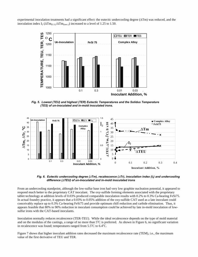
experimental inoculation treatments had a significant effect: the eutectic undercooling degree (∆Tm) was reduced, and the inoculation index I2 (∆Tm(U.I.)/∆Tm(inoc.)) increased to a level of 1.25 to 1.50.
0.1 0.3 0.01 0.03 .1000
1050
1100
1150
1200
1250TEU TER TES
TEM
PER
ATU
RE ,
TEU
, TER
, TES
Inoculant Addition, %
Ο CComplex AlloyFeSi 75Un-Inoculation
Fig. 5. Lowest (TEU) and highest (TER) Eutectic Temperatures and the Solidus Temperature
(TES) of un-inoculated and in-mold inoculated irons.
05
1015202530354045
0 0.1 0.2 0.3 0.4
Inoculant Addition, %
∆T
EU
, ∆T
m, (o C
), I2
x10
■ Complex Alloy* FeSi75
∆Tm
I2
∆TEU
0.1 0.3 0.01 0.03 .0
5
10
15
20
25
30
35
40
45
0
0.5
1
1.5 Tm Tr I
∆T m
, ∆T r
, o C
Inoculant Addition, %
Complex Alloy
FeSi 75 Un-Inoculation ∆∆ 2
I2
Fig. 6. Eutectic undercooling degree (∆Tm), recalescence (∆Tr), inoculation index (I2) and undercooling difference (∆TEU) of un-inoculated and in-mold inoculated irons
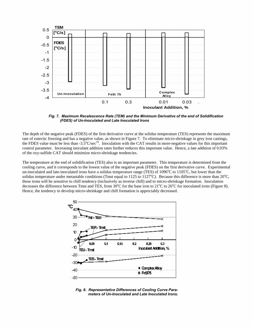
From an undercooling standpoint, although the low-sulfur base iron had very low graphite nucleation potential, it appeared to respond much better to the proprietary CAT inoculant. The oxy-sulfide forming elements associated with the proprietary tablet technology at addition levels of 0.03% produced comparable inoculation results with 0.2% to 0.3% Ca-bearing FeSi75. In actual foundry practice, it appears that a 0.03% to 0.05% addition of the oxy-sulfide CAT used as a late inoculant could conceivably replace up to 0.3% Ca-bearing FeSi75 and provide optimum chill reduction and carbide elimination. Thus, it appears feasible that 80% to 90% reduction in inoculant consumption could be achieved by late in-mold inoculation of low-sulfur irons with the CAT-based inoculants. Inoculation normally reduces recalescence (TER-TEU). While the ideal recalescence depends on the type of mold material and on the modulus of the castings, a range of no more than 5oC is preferred. As shown in Figure 6, no significant variation in recalescence was found; temperatures ranged from 5.5oC to 6.4oC. Figure 7 shows that higher inoculant addition rates decreased the maximum recalescence rate (TEM), i.e., the maximum value of the first derivative of TEU and TER.
0.1 0.3 0.01 0.03 .
0
0.5
-0.5
-1
-1.5
-2
-2.5
-3
-3.5
-4FeSi 75 Un-Inoculation Complex
Alloy
TEM[oC/s]
FDES[oC/s]
Inoculant Addition, %
Fig. 7. Maximum Recalescence Rate (TEM) and the Minimum Derivative of the end of Solidification (FDES) of Un-Inoculated and Late Inoculated Irons
The depth of the negative peak (FDES) of the first derivative curve at the solidus temperature (TES) represents the maximum rate of eutectic freezing and has a negative value, as shown in Figure 7. To eliminate micro-shrinkage in grey iron castings, the FDES value must be less than -3.5oC/sec19. Inoculation with the CAT results in more-negative values for this important control parameter. Increasing inoculant addition rates further reduces this important value. Hence, a late addition of 0.03% of the oxy-sulfide CAT should minimize micro-shrinkage tendencies. The temperature at the end of solidification (TES) also is an important parameter. This temperature is determined from the cooling curve, and it corresponds to the lowest value of the negative peak (FDES) on the first derivative curve. Experimental un-inoculated and late-inoculated irons have a solidus temperature range (TES) of 1096oC to 1105oC, but lower than the solidus temperature under metastable conditions (Tmst equal to 1125 to 1127oC). Because this difference is more than 20oC, these irons will be sensitive to chill tendency (inclusively as inverse chill) and to micro-shrinkage formation. Inoculation decreases the difference between Tmst and TES, from 30oC for the base iron to 21oC to 26oC for inoculated irons (Figure 8). Hence, the tendency to develop micro-shrinkage and chill formation is appreciably decreased.
Fig. 8. Representative Differences of Cooling Curve Para- meters of Un-Inoculated and Late Inoculated Irons.

Thermal analysis interpretation of Figure 8 shows the high undercooling tendency of these very low-sulfur grey irons. Both inoculants significantly reduced undercooling. If the difference between the lowest eutectic temperature and the solidus temperature under metastable conditions (TEU-Tmst) is considered, negative values are obtained for un-inoculated irons. Inoculation changes these values to the positive value range as well as increases these values, but they will remain at relatively low levels, usually from 6oC to 12oC. Similarly, the difference between the highest eutectic temperature and the solidus temperature under metastable conditions (TER-Tmst) remains at a relatively low level, 2oC for un-inoculated iron versus 10oC to 18oC for inoculated irons. The greater the inoculant addition, the larger the difference becomes (Figure 8). This means that, although the formation of free carbides in the first portion of eutectic solidification can be avoided, irons may still remain sensitive to undercooled graphite morphologies. The effects of inoculation were also analyzed by comparing the microstructures of irons treated with different amounts of FeSi75 and CAT. Chill wedge test samples were utilized for the measurements shown in Figure 9. The free carbide amounts shown in Figure 9 were determined along the geometrical centerline of the chill wedge and at different depths from the wedge apex. At distances farthest from the chill wedge, the cooling rates are very shallow. Figure 9 illustrates that an inverse relationship exists and between free carbide levels and distance from the chill wedge apex. As the amount of each inoculant increased, the percentage of free carbides diminished; the amount of free carbides also decreased with increasing inoculant additions and with increasing distance from the apex. The first measurements of free carbides were taken 5mm from the wedge apex and in a clear chill zone. It was found that despite the white iron appearance, the samples contained different amounts of free carbides and a small amount of graphite, depending on the type of inoculant and its addition rate. It was also found that the CAT inoculant was more efficient in eliminating free carbides than FeSi75
0
5
10
15
20
25
30
35
40
0 5 10 15 20 25 30 35 40
Distance from apex of wedge sample, mm
Fre
e C
arb
ides
, %
Un. Inoculated
0.1%
0.2%
0.3%
0
5
10
15
20
25
30
35
40
0 5 10 15 20 25 30 35 40
Distance from apex of wedge sample, mm
Fre
e C
arb
ides
, %
05
10152025303540
0 0.1 0.2 0.3 0.4
Inoculant Addition, %
Fre
e C
arb
ides,
%
■ Complex Alloy * FeSi75
25 mm
40 mm
5 mm
Un. Inoculated
0.01%
0.02%
Complex Alloy
0.03%n.
FeSi75
Fig. 9. Free carbide amounts in wedge samples, at different distances from the apex, in un-inoculated and in-mold inoculated irons.

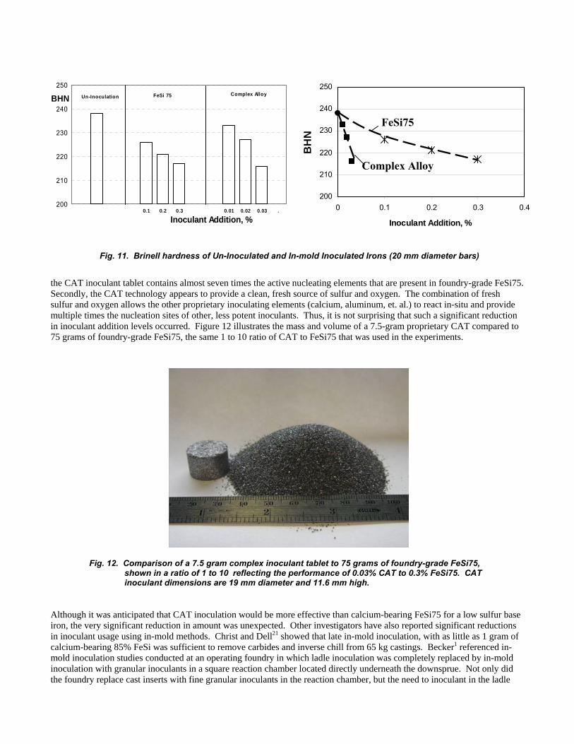
The effects of inoculation were further examined by comparing the microstructures of irons treated with different amounts of FeSi75 and CAT. Chill wedge test samples were again utilized for the measurements shown in Figure 10. Figure 10 also shows an inverse relationship between undercooled graphite levels and distance from the chill wedge apex. The amount of undercooled graphite decreased with increasing distance from the wedge apex. As in the previous graph, Figure 9, the first measurements of undercooled graphite levels were taken 5mm from the chill wedge apex. The CAT inoculant was again more effective in reducing undercooled graphite levels than FeSi75. Overall, it appears that 0.03% CAT in-mold inoculation is much more effective that 0.3% FeSi75. The effect of inoculation with the various alloys on Brinnel hardness was studied utilizing the 20mm diameter bars. These results are shown in Figure 11. There did not appear to be any significant differences in hardness level between the FeSi75 inoculant and the CAT inoculant. Brinell hardness values decreased with increasing inoculant additions, regardless of inoculant type. The CAT inoculant reduced hardness values more rapidly than did the conventional FeSi75 inoculant. The results of this investigation into late inoculation effects of low-sulfur grey irons show that the simultaneous addition of oxygen and sulfur with a proprietary alloy blend in tablet form, greatly improves inoculation response and properties compared with standard calcium-bearing FeSi75. It would be expected that non-tablet, granular CAT inoculants would behave in a similar fashion. When the mole fractions of the active ingredients in both inoculants are taken into consideration,
0
20
40
60
80
100
0 5 10 15 20 25 30 35 40
Distance from apex of wedge sample , mm
Un
der
coo
led
Gra
ph
ite
(D+
E),
%
FeSi75
Un. Inoculated 0.1%
0.2% 0.3%
0
20
40
60
80
100
0 5 10 15 20 25 30 35 40
Distance from apex of wedge sample, mm
Un
der
coo
led
Gra
ph
ite
(D+
E),
%
Complex Alloy
Un. Inoculated
0.01%
0.02%0.03%
0
20
40
60
80
100
0 0.1 0.2 0.3 0.4
Inoculant Addition, %
Unde
erco
oled
Gra
phite
(D+E
), %
5 mm
40 mm
25 mm
■ Complex Alloy * FeSi75
Fig. 10. Undercooled graphite morphologies in wedge samples at different distances
from apex, in un-inoculated and in-mold inoculated irons.
200
210
220
230
240
250
0 0.1 0.2 0.3 0.4
Inoculant Addition, %
BH
N
the CAT inoculant tablet contains almost seven times the active nucleating elements that are present in foundry-grade FeSi75. Secondly, the CAT technology appears to provide a clean, fresh source of sulfur and oxygen. The combination of fresh sulfur and oxygen allows the other proprietary inoculating elements (calcium, aluminum, et. al.) to react in-situ and provide multiple times the nucleation sites of other, less potent inoculants. Thus, it is not surprising that such a significant reduction in inoculant addition levels occurred. Figure 12 illustrates the mass and volume of a 7.5-gram proprietary CAT compared to 75 grams of foundry-grade FeSi75, the same 1 to 10 ratio of CAT to FeSi75 that was used in the experiments.
Fig. 12. Comparison of a 7.5 gram complex inoculant tablet to 75 grams of foundry-grade FeSi75, shown in a ratio of 1 to 10 reflecting the performance of 0.03% CAT to 0.3% FeSi75. CAT inoculant dimensions are 19 mm diameter and 11.6 mm high.
Although it was anticipated that CAT inoculation would be more effective than calcium-bearing FeSi75 for a low sulfur base iron, the very significant reduction in amount was unexpected. Other investigators have also reported significant reductions in inoculant usage using in-mold methods. Christ and Dell21 showed that late in-mold inoculation, with as little as 1 gram of calcium-bearing 85% FeSi was sufficient to remove carbides and inverse chill from 65 kg castings. Becker1 referenced in-mold inoculation studies conducted at an operating foundry in which ladle inoculation was completely replaced by in-mold inoculation with granular inoculants in a square reaction chamber located directly underneath the downsprue. Not only did the foundry replace cast inserts with fine granular inoculants in the reaction chamber, but the need to inoculant in the ladle
Fig. 11. Brinell hardness of Un-Inoculated and In-mold Inoculated Irons (20 mm diameter bars)
FeSi75
Complex Alloy
0.1 0.2 0.3 0.01 0.02 0.03 .200
210
220
230
240
250FeSi 75 Un-Inoculation Complex AlloyBHN
Inoculant Addition, %

was also eliminated, resulting in a significant cost savings. Becker22 further felt that in-mold inoculation with an oxy-sulfide inoculant, placed in a reaction basin in the gating system, could totally eliminate ladle inoculation in his 2005 paper. Although the incorrect perception of sulfur as a harmful impurity in both grey and ductile irons has slowed acceptance of this new technology among foundrymen, controlled additions of sulfur- and oxygen-containing compounds simultaneously with inoculation greatly assist in the nucleation of graphite in molten irons. Recently, one patent has been applied for23 and three patents have been issued8,17,24 relating to the addition of oxy-sulfide enhancing additives that allow for improved performance of traditional foundry inoculants. The basis of these patents is to provide a method to improve inoculation effectiveness in cast irons that have low nucleation properties, such as irons with low dissolved oxygen levels and low sulfur levels. Providing chemically fresh sulfur surfaces appears to make all grey iron inoculants perform better. Lastly, the technology presented in this paper shows promise of reducing the usage of ferrosilicon-based inoculants by the substitution of oxy-sulfide based CAT-type inoculants. CONCLUSIONS The proprietary CAT inoculant incorporating potent oxy-sulfide nuclei-forming elements was compared with calcium-bearing foundry-grade FeSi75 in late inoculation of a 3.9% carbon-equivalent, low-sulfur grey iron (0.02%S). The addition rates of the two inoculants were tested at a ratio of 1 to 10, oxy-sulfide containing CAT inoculant to FeSi75 inoculant, respectively. The conclusions are based mainly on the use of thermal analysis, although chill depth, microstructure and Brinell hardness also are considered. The evidence presented has led to the following conclusions: 1. A synthetic base cast iron—made without any pig iron and having a 3.9% carbon-equivalent and a very low sulfur content of 0.02%—undergoes solidification that is characterized by excessive eutectic undercooling degree (41oC). 2. Late in-mold inoculation of low sulfur grey irons appears to have a very strong effect on subsequent solidification. It was found that inoculating with either a calcium-bearing FeSi75 or a potent, CAT inoculant significantly decreased undercooling, reduced the level of free carbides and undercooled graphite structures, reduced chill and microshrinkage tendency. 3. The CAT inoculant that incorporated potent oxy-sulfide nuclei-forming elements was found to be very effective, when utilized in an in-mold application with low-sulfur grey irons. 4. A 0.03% addition of the CAT inoculant produced results at least comparable with additions of 0.2% to 0.3% calcium- bearing foundry-grade FeSi75 in low-sulfur late inoculated grey irons. A maximum addition level of 0.05% CAT inoculant appears sufficient for efficient in-mold inoculation of grey iron. 5. Low sulfur grey iron inoculated with the proprietary oxy-sulfide CAT inoculant, was found to be less sensitive to chill formation and micro-shrinkage compared with foundry-grade FeSi75 treatments. 6. Although the silicon contribution of the CAT inoculant was very low, its performance was equal to or better than a ferrosilicon-based inoculant with double the silicon content, even at a 90% lower addition rate. ACKNOWLEDGEMENTS The authors would like to recognize and thank Ms. Kelly K. Tackett for reviewing and editing this paper. REFERENCES
1. Becker, P., “Using In-Mold Inoculants at Low Pouring Temperatures,” Proceedings of the AFS Cast Iron Inoculation Conference, pp 113-118, (September 29-30, 2005).
2. Bilek, P.J., Dong, J.M., and McCluhn, T.K., “The Roles of Ca and Al in Inoculation of Grey Iron, ”AFS Transactions, Vol 80, pp.183-188, (1972)
3. Chisamera, M., Riposan, I., Stan. S., and Skaland, T., “Undercooling-Chill Size – Structure Relationship in the Ca/Sr Inoculated Grey Irons under Sulphur/Oxygen Influence,” Technical Communications of the 64th World Foundry Congress, Paper R0 62, (September 11-14, 2000)
4. Riposan, I., Chisamera, M., Stan, S., Skaland, T., Onsoien, M.O., “Analyses of Possible Nucleation Sites in Ca/Sr Over-Inoculated Grey Irons,” AFS Transactions, Vol.109, pp.1151-1162, (2001)
5. Riposan, I., Chisamera, M., Stan, S., and Skaland, T., “Graphite Nucleants (Microinclusions) Characterization in Ca/Sr Inoculated Grey Irons,” International Journal on Cast Metals Research, Vol. 16, No. 1-3, pp.105-111, (2003)
6. Riposan, I., Chisamera, M., Stan, S., Skaland, T., “The Key Role of Residual Aluminium in Chill Tendency and Structure Characteristics of Un-Inoculated and Ca/Sr Inoculated Grey Irons,”Proceedings of the 66th World Foundry Congress, Vol.1, pp. 775-790, (September, 2004).
7. Riposan, I., Chisamera, M., Stan, S., Skaland, T., “A New Approach on the Inoculated Grey Irons,” Proceedings of the AFS Cast Iron Inoculation Conference, pp 31-42, (September 29-30, 2005)

8. Naro, R.L., U.S. Patent No.6, 293, 988 B1, (September, 2001). 9. Foundry Management and Technology, “Newly Patented Inoculant Boasts Benefits for Gray and Ductile Irons,” pp. 20, (March 2002) 10. Naro, R.L., Wallace, J.F., “Trace Elements in Cast Iron,” AFS Transactions, AFS, Vol. 77, pp 311, (1969) 11. Naro, R.L., Wallace, J.F., “Trace Elements in Gray Iron,” AFS Transactions, Vol. 78, pp 229, (1970) 12. Strande, K., “Influence of Inoculant, Amount of Inoculant, and Iron Sulfide Content on Tool Wear by Turning Pearlitic Grey Cast Iron,” 51st. International Foundry Congress, Lisbon, (1984) 13. Riposan, I., Chisamera, M., Simionescu, G., RO Patent No. 101339 (1988) 14. Chisamera, M., Riposan, I., Liliac, M., “High Active Inoculant Ferroalloy to Control Graphite Morphology and Nucleation Ability in Cast Iron,” INFACON7, Publishers: FFF, Trondheim, Norway, pp. 742-749 (1995) 15. Chisamera, M., Riposan, I., Barstow, M., “The Importance of Sulfur to Control Graphite Nucleation in Cast Irons,” AFS International Inoculation Conference, Chicago, (April 6-8, 1998) 16. Riposan, I., Chisamera, M., Sofroni, L., Stan, S., Liliac, M., “Contributions to the Development of Nodular and Vermicular Cast Iron Technologies,” 63rd World Foundry Congress, Budapest, (1998) 17. Skaland, T., U.S. Patent No.6,102,983, (August 15, 2000), International Patent W099/29911 18. Skaland, T., “A new Approach to Ductile Iron Inoculation,” 105th AFS Casting Congress, Dallas, Paper 01-078. (2001) 19. Sillen, R.V., “Optimizing Inoculation Practice by means of Thermal Analysis, Conference Proceedings, AFS- International Inoculation Conference, Chicago, (1998) 20. Sillen, R.V., Nova Cast Technologies, private communication 21. Dell, W.J., Christ, R.J., “Chill Elimination in Ductile Iron by Mold Inoculation, Proceedings of AFS-CMI Conference, (Febuary 6-7, 1979) 22. Becker, P., Lufkin Industries, private communication, (August 2006) 23. Loper, C.R. Jr., Lekakh, S. K., U.S. Patent Application No. 20050050992, (March 10, 2005) 24. Naro, R.L., U.S. Patent No. 6,866,696B1, (March 15, 2005)