comparison of constitutive soil models for · pdf filethe further development of dynamic...
TRANSCRIPT
European Congress on Computational Methods in Applied Sciences and Engineering (ECCOMAS 2012)
J. Eberhardsteiner et.al. (eds.) Vienna, Austria, September 10-14, 2012
COMPARISON OF CONSTITUTIVE SOIL MODELS FOR THE SIMULATION OF DYNAMIC ROLLER COMPACTION
Johannes Pistrol1, Franz-Josef Falkner2, Dietmar Adam1, and Christoph Adam2
1 Institute of Geotechnics, Center of Ground Engineering, Soil and Rock Mechanics Vienna University of Technology
Karlsplatz 13/220/2, 1040 Vienna, Austria {johannes.pistrol, dietmar.adam}@tuwien.ac.at
2 Unit of Applied Mechanics, University of Innsbruck Technikerstr. 13, 6020 Innsbruck, Austria
{franz.falkner, christoph.adam}@uibk.ac.at
Keywords: constitutive soil model, dynamic compaction, roller, soil dynamics
Abstract. Realistic modeling of dynamic roller soil compaction requires the consideration of various sources of nonlinearities. An appropriate contact formulation is necessary to model the interaction between soil and roller. Moving of the roller results in large rigid body mo-tions, which should be taken into account in numerical simulations. Furthermore, a nonlinear constitutive law should describe roller induced soil compaction. In the presented study two different rate-independent elasto-plastic constitutive laws for soil are evaluated on their abil-ity to predict the natural behavior of soil subjected to dynamic loading of a moving roller. One of the constitutive laws is the Mohr-Coulomb criterion, where the evolution of plastic strains is modeled by means of a non-associated flow rule. According to the implemented smooth flow potential the volumetric plastic strains increase in case of yielding. The second constitutitive model tested is based on the Drucker-Prager yield surface, which describes shear failure, however, extended by a cap to consider also failure in compression. To each of both yield surfaces a different flow potential of elliptic shape is assigned to account for the evolution of volumetric plastic strains.

Johannes Pistrol, Franz-Josef Falkner, Dietmar Adam, and Christoph Adam
2
1 INTRODUCTION
In geotechnical engineering large-scale compaction plays an important role for the con-struction of various civil structures such as dams, embankments, roads, and railways. Vibrat-ing rollers, rapid impact compaction, and many other compaction procedures are dynamic methods, which were developed in an effort to make compaction devices lighter but simulta-neously even more efficient. The further development of dynamic compaction methods re-quires extensive experimental field test accompanied by parametric numerical simulations for a better understanding and optimization of the compaction process.
Realistic numerical modeling of dynamic roller soil compaction requires the consideration of different nonlinearities. An appropriate contact formulation is necessary to model soil – roller interaction. Moving of the roller results in large rigid body motions, which should be also taken into account in the numerical simulations. During dynamic roller compaction vari-ous operation modes of vibrating rollers occur, which strongly influence the roller compaction process. These modes of operation are discussed in earlier publications such as [1,2], and thus, they are out of scope of the present paper.
In this paper two different rate-independent elasto-plastic material models are evaluated on their ability to reproduce natural soil behavior under dynamic loading of roller compaction.
Elasto-plastic constitutive models comprise a yield surface and a plastic flow potential. Subsequently, these components are described for the models of Mohr-Coulomb and Drucker-Prager. Besides the yield surface and the plastic flow potential the Drucker-Prager/cap model also includes a hardening/softening law for yielding on the cap. Furthermore, the parameter transformation between the Mohr-Coulomb and the Drucker-Prager model is explained. Note that numerous numerical simulations were performed for the rapid impact compaction method in ABAQUS® Standard in previous publications (e.g. [3,4,5]), where a material model based on Mohr-Coulomb’s constitutive law was used. Section 3 of this paper gives a detailed de-scription of the numerical model with the roller’s and soil’s parameters for the numerical sim-ulations. In Section 4 the results of the numerical simulations, i.e. the volumetric plastic strains and the vertical displacements of the top layer’s surface, are set in contrast for both material models. The paper concludes with a description of the limitations of conventional material models in connection with dynamic roller compaction and compaction in general.
2 MATERIAL MODELS
2.1 Soil behavior subjected dynamic roller compaction
Dynamic roller compaction as well as soil compaction in general is associated with perma-nent deformations. Therefore, an elasto-plastic material model is required to describe the in-fluence of compaction properly.
In many geotechnical applications the formation of shear bands leads to plastic soil defor-mations. However, during soil compaction plastic material behavior is the result of a change of soil packing from loose to compact. The exceedance of grain-to-grain friction strength and compression strength leads to a volume contraction.
For geotechnical applications a very popular failure/strength criterion is the Mohr-Coulomb criterion, which is based on two soil parameters, i.e. cohesion c and angle of fric-tion ϕ . Both parameters are physically consistent and can be derived from standard laborato-ry tests. The Mohr-Coulomb criterion assumes that failure is controlled by the maximum shear stress, which depends on the normal stress. Within this formulation of the failure crite-rion the impact of soil compaction cannot be considered for a pure critical hydrostatic stress state as it occurs in the process of compaction.

Johannes Pistrol, Franz-Josef Falkner, Dietmar Adam, and Christoph Adam
3
In an effort to overcome these limitations the application of the modified Drucker-Prager/cap model is proposed and tested on its capability to describe the process of dynamic roller compaction.
The following descriptions of the Mohr-Coulomb and the Drucker-Prager/cap model are based on the explanations by Helwany [6].
2.2 Mohr-Coulomb model
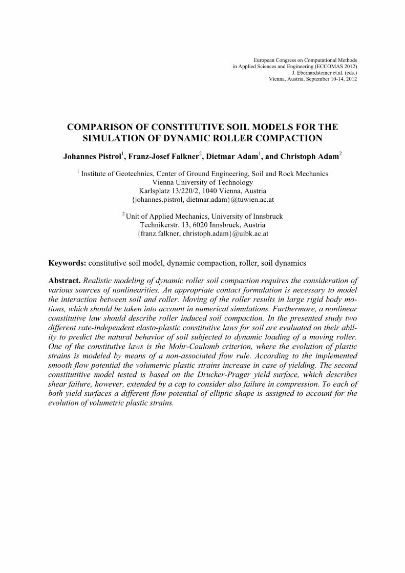
In Figure 1(a) a meridional section of the Mohr-Coulomb yield surface f is depicted, where p denotes the hydrostatic pressure and q is the deviatoric stress measure. In the Mohr-Coulomb model, and also in the Drucker-Prager/cap model, an additive strain increment de-composition is assumed:
dε = dε e + dε p (1)
dε is the total strain increment, while dε e and dε p is the elastic and plastic strain increment, respectively.
The elastic part of the material behavior is modeled as linear and isotropic. For general stress states yielding depends on three stress invariants,
f = Rmcq − p tanϕ − c = 0 (2)
Rmc is the Mohr-Coulomb deviatoric stress measure defined as:
Rmc Θ,ϕ( ) = 13cosϕ
sin Θ +π3
⎛⎝⎜
⎞⎠⎟+13cos Θ +
π3
⎛⎝⎜
⎞⎠⎟tanϕ (3)
Variable ϕ denotes the slope of the Mohr-Coulomb yield surface in the meridional stress plane, which is also referred to as the friction angle of the material (see Figure 1). c is the material cohesion, and Θ is the deviatoric polar angle [6],
cos 3Θ( ) = rq
⎛⎝⎜
⎞⎠⎟
3
(4)
The three stress invariants are the equivalent pressure stress,
p = −13trace σ( ) (5)
the Mises equivalent stress,
q = 32S :S( ) (6)
and the deviatoric stress,
r = 92S ⋅S :S⎛
⎝⎜⎞⎠⎟
13 (7)
The stress deviator S is defined as: S = σ + pI (8)
with σ denoting Cauchy’s stress tensor, and Ι is the second order identy tensor.
Johannes Pistrol, Franz-Josef Falkner, Dietmar Adam, and Christoph Adam
4
c
p
q
!
p
qd!
p
d!vol, p
!
p
t
d
!
pa pb
fns= fn+1
s
fnc
fn+1c
p
t
d!vol, p
d!p
pa
d!p
d!vol, p
gs
gc
g
(a) (b)
(a) (b)
f
!c
Figure 1: Mohr-Coulomb model: (a) yield surface, (b) flow potential [6,7]
The plastic strain increment dε p is modeled in terms of a non-associated flow rule. Poten-tial flow is assumed, thus
dε p = dλ ∂g∂σ
(9)
In this expression g denotes the flow potential and λ is the consistence parameter. The flow potential,
g = ξc tanψ( )2 + Rmwq( )2 − p tanψ (10)
is a hyperbolic function in the meridional stress plane and a smooth elliptic function in the deviatoric stress plane. ξ is a parameter for the meridional eccentricity, which defines the rate of the function approaching the asymptote, and it is considered to be ξ = 0.1. The param-eter ψ is the dilatation angle in the p − q plane at high confining pressure, see Figure 1b. However, ψ is not identical with the commonly known dilatation angle derived from stand-ard laboratory tests. According to the smooth flow potential proposed by Menétrey and Wil-liam [8] the volumetric plastic strain dε p increases in case of yielding. The dilatation angle ψ is used to control this yield-induced volume increase.
The flow potential is also smooth and continuous in the deviatoric stress plane. For this flow potential the following deviatoric elliptic function [9] is adopted,
Rmw Θ,e( ) = 4 1− e( )2 cos2Θ + 2e −1( )2
2 1− e( )2 cosΘ + 2e −1( ) 4 1− e2( )cos2Θ + 5e2 − 4eRmc
π3,ϕ⎛
⎝⎜⎞⎠⎟
(11)
Rmc (π / 3,ϕ ) = 3− sinϕ( ) 6cosϕ , and e is a parameter for the “out-of-roundness”, which de-pends on the friction angle. is calculated by matching the flow potential with the yield sur-face in triaxial tension and compression in the deviatoric plane:
e = 3− sinϕ3+ sinϕ
(12)
2.3 Modified Drucker-Prager/cap model
The Drucker-Prager/cap model allows to model yielding primarily induced by hydrostatic pressure. The yield surface includes a shear failure surface such as in the Mohr-Coulomb model, but it is extended by a “cap” to provide for pressure-dependent yielding. In the transi-tion region between the shear failure surface and the cap a transition surface is introduced to
e

Johannes Pistrol, Franz-Josef Falkner, Dietmar Adam, and Christoph Adam
5
provide for a smooth yield surface. Additive strain rate decomposition according to Eq. (1) is assumed. Elastic behavior is modeled as linear and isotropic, similar to the Mohr-Coulomb model. Yielding is expressed in terms of three stress invariants, see Eqs. (5) – (8), however, extended by the definition of a deviatoric stress measure,
t = q21+ 1
K− 1− 1
K⎛⎝⎜
⎞⎠⎟
rq
⎛⎝⎜
⎞⎠⎟
3⎡
⎣⎢⎢
⎤
⎦⎥⎥
(13)
K is a parameter that allows matching of different stress values in tension and compression in the deviatoric plane and a smooth approximation of the Mohr-Coulomb surface. For K = 1 the yield/flow surface becomes (the Mises) circle in the deviatoric plane, and t = q . K = 0.778 is the limit for a yield surface that is still convex (see Figure 2). With the devia-toric stress measure t the Drucker-Prager shear failure surface is written as
f s = t − p tanβ − d = 0 (14)
where β and d are the material’s angle of friction and the cohesion in the p − t plane. The cap yield surface has an elliptical shape
f c = p − pa( )2 + Rt1+α −α cosβ( )
⎡
⎣⎢
⎤
⎦⎥
2
− R d + pa tanβ( ) = 0 (15)
Thereby, material parameter R controls the eccentricity of the elliptical cap surface.
Figure 2: Mohr-Coulomb and two typical Drucker-Prager yield surfaces in the deviatoric plane [6,7]
�1 �2
�3
K = 1.0K = 0.778

Johannes Pistrol, Franz-Josef Falkner, Dietmar Adam, and Christoph Adam
6
c
p
q
!
p
qd!
p
d!vol, p
!
p
t
d
!
pa pb
fns= fn+1
s
fnc
fn+1c
p
t
d!vol, p
d!p
pa
d!p
d!vol, p
gs
gc
g
(a) (b)
(a) (b)
f
!c
Figure 3: Drucker-Prager/cap model: (a) yield surface, (b) flow potential [6,7]
The hydrostatic pressure is the actual intersection of the cap-surface and the shear failure surface, and it is determined by
pa =pb − Rd1+ R tanβ( ) (16)
To circumvent numerical problems, a smooth surface between the shear failure surface and the cap surface is introduced. The shape of this transition surface is controlled by the parame-ter α and the mathematical definition reads as:
f t = p − pa( )2 + t − 1− αcosβ
⎛⎝⎜
⎞⎠⎟d + pa tanβ( )⎡
⎣⎢
⎤
⎦⎥
2
−α d + pa tanβ( ) = 0 (17)
Hydrostatic compression leads to yielding on the cap and volumetric contraction, while yielding on the shear failure surface results in dilatant material behavior.
The Drucker-Prager/cap defines plastic flow by a non-associated flow potential on the shear failure yield surface and on the transition yield surface, and an associated flow potential on the cap. The flow potential surface in the meridional plane is formed by two elliptical sur-faces, see Figure 3b. The portion in the cap region gc is identical to the cap yield surface,
gc = p − pa( )2 + Rt1+α −α cosβ⎡
⎣⎢
⎤
⎦⎥
2
(18)
The portion in the failure and transition regions corresponds to the non-associated flow poten-tial:
gs = p − pa( ) tanβ⎡⎣ ⎤⎦2+ t1+α −α cosβ⎡
⎣⎢
⎤
⎦⎥
2
(19)
Within the Drucker-Prager/cap model, compaction of soil is primarily associated with yielding on the cap surface. If the soil is compacted in one load cycle, a higher stress state is necessary for further compaction in subsequent cyles. To model this behavior, the cap surface f c expands in the direction of the hydrostatic pressure in two consecutive loading-cycles; see
Figure 3a. The associated hardening function depends on the volumetric plastic strain ε vol ,p (see also section 2.4). No hardening function is applied to the shear failure surface f s .

Johannes Pistrol, Franz-Josef Falkner, Dietmar Adam, and Christoph Adam
7
2.4 Parameter transformation between the Drucker-Prager model and the Mohr-Coulomb model
To ensure the comparability of calculated stresses and strains the material parameters of both models must be transferred into each other. Since the cohesion c and the angle of fric-tion ϕ of the Mohr-Coulomb model can be derived from standard laboratory tests, the Druck-er-Prager parameters d and β are adjusted to the Mohr-Coulomb parameters.
Two specific states of stress must be selected such that one edge of the Mohr-Coulomb pyramid coincides with the generatrix of the Drucker-Prager cone. Either the tension or the compression meridian can be adjusted. In both cases the apex of the Mohr Coulomb pyramid coincides with the apex of the Drucker-Prager cone. The stress at the apex can be written as
σ a =c
tanϕ (20)
For modeling soil compaction the Drucker-Prager cone should be tangential to the Mohr-Coulomb pyramid at its compression meridian (Θ = π 3 , see Figure 2). Therefore, the uniax-ial state of compression can be expressed according to
σ c =2c
secϕ − tanϕ (21)
Together with Eqs. (20) and (21) the angle of friction β and the cohesion d of the Druck-er-Prager model can be re-written as
tanβ =3σ c
3σ a +σ c
and d =3σ c
3σ a +σ c
σ a (22)
As outlined in section 2.3 a hardening/softening law as a function relating the hydrostatic compression yield stress and the corresponding volumetric plastic strain has to be defined for the cap of the Drucker-Prager/Cap model. Helwany [6] obtains the cap hardening curve from a standard isotropic consolidation test, at which the volumetric plastic strain is given as
ε vol , p = Cc − Cs
2.3 1+ e0( ) lnpbp0
(23)
Cc and Cs is the compression index and the swelling index, respectively, measured in the mean effective stress-void ratio diagram of an isotropic consolidation test. e0 denotes the void ratio, and p0 is the initial mean effective stress before loading, i.e. it corresponds to the geostatic stress state.
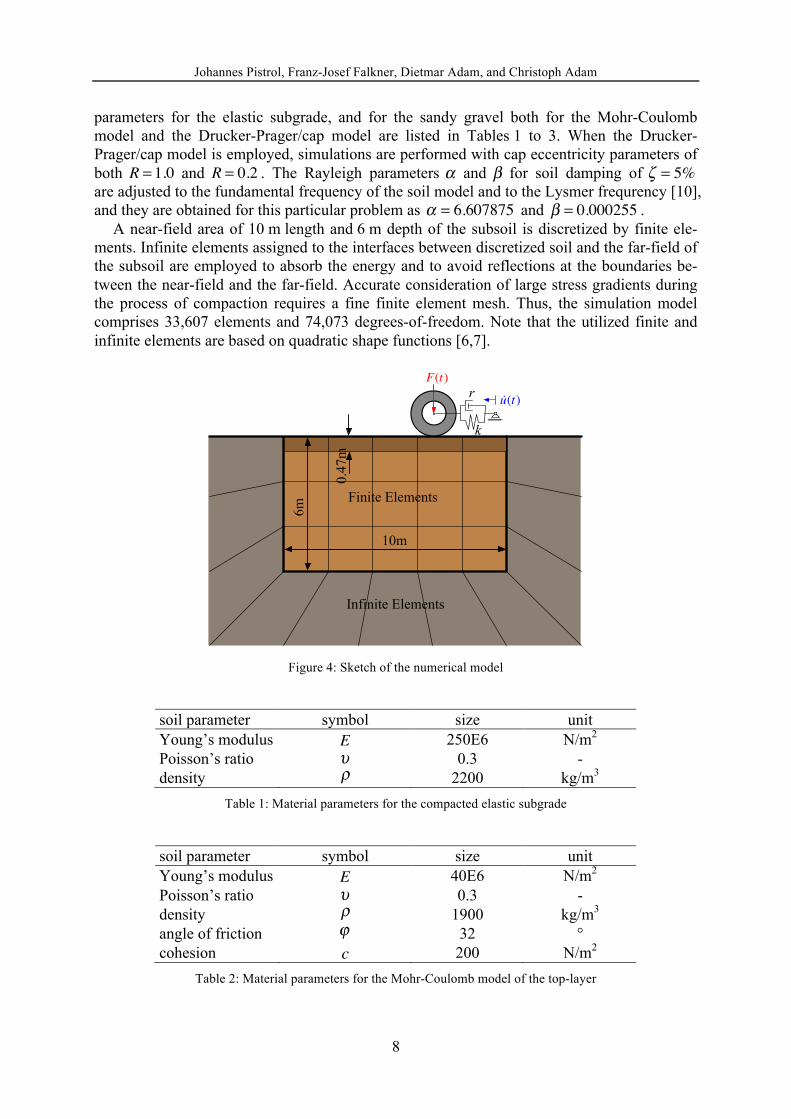
3 NUMERICAL MODEL
At the onset it is noted that all compuations are performed with the commercial numerical simulation platform ABAQUS® [7]. It can be assumed that the displacement field of the soil does not depend on the coordinate in direction of the roller axis. Thus, for the underlying nu-merical model the condition of plane strain applies.
It is assumed that a layer of sandy gravel (to be compacted) rests on an elastic (compacted) subgrade. The top-layer of the soil medium exhibits a thickness of 0.47 m with infinite hori-zontal extension, and its constitutive behavior is described by the rate-independent plasticity models of Mohr-Coulomb and Drucker-Prager/cap, respectively, as decribed before. The un-derlying subgrade is an elastic, homogenous and isotropic infinite halfplane. The constitutive
Johannes Pistrol, Franz-Josef Falkner, Dietmar Adam, and Christoph Adam
8
parameters for the elastic subgrade, and for the sandy gravel both for the Mohr-Coulomb model and the Drucker-Prager/cap model are listed in Tables 1 to 3. When the Drucker-Prager/cap model is employed, simulations are performed with cap eccentricity parameters of both R = 1.0 and R = 0.2 . The Rayleigh parameters α and β for soil damping of ζ = 5% are adjusted to the fundamental frequency of the soil model and to the Lysmer frequrency [10], and they are obtained for this particular problem as α = 6.607875 and β = 0.000255 .
A near-field area of 10 m length and 6 m depth of the subsoil is discretized by finite ele-ments. Infinite elements assigned to the interfaces between discretized soil and the far-field of the subsoil are employed to absorb the energy and to avoid reflections at the boundaries be-tween the near-field and the far-field. Accurate consideration of large stress gradients during the process of compaction requires a fine finite element mesh. Thus, the simulation model comprises 33,607 elements and 74,073 degrees-of-freedom. Note that the utilized finite and infinite elements are based on quadratic shape functions [6,7].
Finite Elements
Infinite Elements
10m
6m
F(t)
k
r
!u(t)
0.4
7m
Figure 4: Sketch of the numerical model
soil parameter symbol size unit Young’s modulus E 250E6 N/m2 Poisson’s ratio υ 0.3 - density ρ 2200 kg/m3
Table 1: Material parameters for the compacted elastic subgrade
soil parameter symbol size unit Young’s modulus E 40E6 N/m2 Poisson’s ratio υ 0.3 - density ρ 1900 kg/m3
angle of friction ϕ 32 ° cohesion c 200 N/m2
Table 2: Material parameters for the Mohr-Coulomb model of the top-layer

Johannes Pistrol, Franz-Josef Falkner, Dietmar Adam, and Christoph Adam
9
soil parameter symbol size unit Young’s modulus E 40E6 N/m2 Poisson’s ratio υ 0.3 - density ρ 1900 kg/m3
angle of friction β 52.16 ° cohesion d 412 N/m2 compression index Cc 0.001 - swelling index Cs 0.0001 - void ratio e0 0.6 - matching parameter K 0.778 - cap eccentricity R 0.2 / 1.0 -
Table 3: Material parameters for the Drucker-Prager/cap model of the top layer
The surface to surface contact between the drum and the top-layer is formulated by means of Coulomb’s law of friction utilizing a friction parameter of µ = 0.3 .
The rollers drum is modeled as an analytical rigid hollow cylinder of 1.6m length. The out-er radius of the cylinder is r2 = 0.6m . The inner radius and the density are adjusted to match the actual mass and mass moment of the drum provided by the manufacturer.
For the drive mechanism of the drum a constant drive torque is applied to the reference node at the drum axis. Additionally, a defined horizontal velocity profile is applied to a se-cond reference node. Both reference nodes are coupled with a spring-damper element to allow the drum to react to the actual soil condition, but also to ensure an almost constant drum speed u of 4 km/h during compaction. A periodic harmonic vertical force F t( ) with a frequency of 40 Hz and an amplitude of 67,031 N is applied to the reference node at the drums axis to model drum vibrations.
During the first second of computational time the geostatic stress state is applied to the model, followed by one second for positioning the drum on the top layer’s surface and load-ing. The drum moves with speed u from right to left starting at computational time t = 2s , accelerating for 0.25s , then moving at a constant speed of 4 km/h for 4.5s , before decelerat-ing for another 0.25s and stopping at computational time t = 7s . Subsequently, the drum moves for three seconds in the opposite direction from left to right with the same velocity se-quence.
4 RESULTS
4.1 Volumetric plastic strains
It is emphasized that accurate modeling of the soil density is not aim of this study. Instead, it is assumed that the roller-induced volumetric plastic soil strains define the degree of com-paction of the top-layer.
In Figures 5 to 8 the volumetric negative (compaction) and positive (dilation) plastic soil strains ε vol ,p at computational time instants t = 7s and t = 10s are depicted for soil modeling based on the Drucker-Prager/cap model with an eccentricity parameter of R = 1.0 and R = 0.2 , respectively.

Johannes Pistrol, Franz-Josef Falkner, Dietmar Adam, and Christoph Adam
10
Figure 5: Volumetric plastic strain distribution ε vol ,p based on Drucker-Prager/cap model with eccentricity pa-rameter R = 0.2 at t = 7s . Top: negative volumetric plastic strains −ε vol ,p (compaction). Bottom: positive vol-
umetric plastic strains +ε vol ,p (dilation)
Figure 6: Volumetric plastic strain distribution ε vol ,p based on Drucker-Prager/cap model with eccentricity pa-rameter R = 0.2 at t = 10s . Top: negative volumetric plastic strains −ε vol ,p (compaction). Bottom: positive vol-
umetric plastic strains +ε vol ,p (dilation)

Johannes Pistrol, Franz-Josef Falkner, Dietmar Adam, and Christoph Adam
11
Figure 7: Volumetric plastic strain distribution ε vol ,p based on Drucker-Prager/cap model with eccentricity pa-rameter R = 1.0 at t = 7s . Top: negative volumetric plastic strains −ε vol ,p (compaction). Bottom: positive volu-
metric plastic strains +ε vol ,p (dilation)
Figure 8: Volumetric plastic strain distribution ε vol ,p based on Drucker-Prager/cap model with eccentricity pa-rameter R = 1.0 at t = 10s . Top: negative volumetric plastic strains −ε vol ,p (compaction). Bottom: positive vol-
umetric plastic strains +ε vol ,p (dilation)

Johannes Pistrol, Franz-Josef Falkner, Dietmar Adam, and Christoph Adam
12
Figure 9: Positive volumetric plastic strain distribution +ε vol ,p (dilation) based on Mohr-Coulomb model at
Figure 10: Positive volumetric plastic strain distribution +ε vol ,p (dilation) based on Mohr-Coulomb model at
In Figures 5 to 8 contractant plastic behavior can be observed right below the drum and in larger depths of the elasto-plastic top layer. The negative volumetric plastic strains are larger for an eccentricity parameter of , where yielding on the cap is more dominant. How-ever, Rayleigh wave induced shear failure occurs in the top-layer close to the surface, and therefore, dilatant plastic behavior is much more pronounced compared to the negative volu-metric plastic strains below. Also in those regions below the drum, where the biggest contrac-tions occur at at time t = 10s dilatant plastic behavior dominates the dynamic soil response.
The flow potantial according Eq. (9) implemented in the Mohr-Coulomb model yields only positive volumetric plastic strains (dilation). These strains must be determined subsequently from the strain tensor, because ABAQUS® does not provide this quantity by default. There-fore, the volumetric plastic strains for t = 7s and t = 10s can only be displayed on the unde-formed/ initial geometry (see Figures 9 and 10).
In Figure 11 vertical displacements of one single node at the top layer’s surface are depict-ed for all three simulations. The drum passes this node at time t = 5.9s . The roller stops at t = 7.0s , turns and passes the node again at t = 8.1s . The bow wave (two positive peaks) ob-served on site is also clearly visible in the numerical outcomes for all considered models. The ground heaving after ten seconds based on the Mohr-Coulomb model is about ten times larger than the heaving predictions based on the Drucker-Prager/cap model with an eccentricity pa-rameter of R = 1.0 .
t = 7s
t = 10s
R = 1.0
t = 7s

Johannes Pistrol, Franz-Josef Falkner, Dietmar Adam, and Christoph Adam
13
0 1 2 3 4 5 6 7 8 9 10
0
2
4
·10�2
t [s]
u2[m
]
CP, R=1.0CP, R=0.2
MC
Figure 11: Vertical displacement of a single node at surface of the top layer. MC: Mohr-Coulomb model. CP:
Drucker-Prager/cap model with eccentricity parameter R = 1.0 and R = 0.2 , respectively
5 CONCLUSION
In this paper the Mohr-Coulomb model and the Drucker-Prager/cap model were tested on their capability to describe the process of dynamic roller soil compaction. While they can be applied to describe inelastic soil behavior of many geotechnical problems, there are certain limitations when plastic material behavior is supposed to result in volume reduction, as it is observed during soil compaction.
5.1 Yield surface
The yield surface of the Mohr-Coulomb material model is an open pyramid with its apex at p = −c cotϕ −ξ( ) (compare with Figure 1a). Therefore, shear failure can be predicted correct-
ly, but failure under hydrostatic compression is not possible. The cone of the Drucker-Prager model with coefficient K = 0.778 is very similar to the
Mohr-Coulomb pyramid (Figure 2), however, extended by a cap in compression, and thus, it provides also for failure under hydrostatic compression. Additionally, a hardening law is de-fined at the cap to account for strength hardening. However, hardening due to shear failure cannot be modeled (see Figure 3a).
5.2 Flow potential
In the Mohr-Coulomb model the evolution of the plastic strain dε p is modeled in terms of a non-associated flow rule, where plastic deformations always lead to dilatancy (Figure 1b). Hence, plastic soil deformation induced by dynamic roller compaction results in a volume in-crease and ground heaving (see Figures 9 to 11) instead of a soil settlement as observed on site.
The stresses in the soil directly below the drum are dominated by hydrostatic compression. Therefore, the cap is yielding when the Drucker-Prager/cap model is employed. The flow po-tential on the cap provides for a volume contraction as expected for compaction. The out-comes shown in Figures 5 to 8 right below the drum are plausible. However, Rayleigh waves induce tensile stresses close to the surface of the top layer, and subsequently, yielding on the Drucker-Prager cone. Similar to the Mohr-Coulomb model yielding on the Drucker-Prager cone results in a volume increase and further in a ground heaving (compare with Figures 5 to

Johannes Pistrol, Franz-Josef Falkner, Dietmar Adam, and Christoph Adam
14
8). The positive vertical displacements of the top layer’s surface are smaller for an eccentrici-ty parameter of R = 1.0 than for R = 0.2 , because a larger value of R increases the yield sur-face of the cap. In that case, yielding on the cap is more dominant compared to yielding on the cone, resulting in a volume contraction. Ground heaving predicted with the Drucker-Prager/cap model with parameter R = 1.0 is about ten times smaller than heaving calculated with the Mohr-Coulomb model. However, volume increase and settlement due to the vibrat-ing drum is still exceeded by the volume increase induced by yielding on the shear failure sur-face (Figure 11).
The definition of the yield surface of the Mohr-Coulomb model and especially the yield surface of the Drucker-Prager model, which is extended by a cap to provide for pressure de-pendent yielding, are both applicable to identify plastic deformations in the subsoil subjected to dynamic roller compaction.
However, the formulation of the flow potential for both material models does not consider appropriately plastic soil behavior after shear failure. Shear failure results in a volume con-traction as it is observed for soil compaction, where the soil packing changes from loose to compact.
5.3 Outlook
The flow potentials of common geotechnical material models are formulated to provide for the formation of shear bands in case of plastic material behavior. To describe the process of compaction properly the flow potential has to be formulated to ensures volume contraction for shear failure as well as pressure dependent yielding on the cap [11]. The top layer with elasto-plastic material behavior was considered with a constant stiffness for both models. While the hardening law at the Drucker-Prager’s cap provides for an increase of strength, it is not possi-ble to take into account the increase of soil stiffness. Further research in the field of constitu-tive soil models should aim at developping models with flow potentials that provide for a volume reduction in case of shear failure.
REFERENCES
[1] D. Adam: Flächendeckende Dynamische Verdichtungskontrolle (FDVK) mit Vibration-swalzen (in German). Doctoral Thesis, Vienna University of Technology, 1996.
[2] F. Kopf: Flächendeckende Dynamische Verdichtungskontrolle (FDVK) bei der Ver-dichtung von Böden durch dynamische Walzen mit unterschiedlichen Anregungsarten (in German). Doctoral Thesis, Vienna University of Technology, 1999.
[3] F.-J. Falkner, C. Adam, I. Paulmichl, D. Adam, J. Fürpass: Rapid impact compaction for middle-deep improvement of the ground – numerical and experimental investigation. Proceedings 14th Danube-European Conference on Geotechnical Engineering. From Research to Design in European Practice (2010).
[4] F.-J. Falkner, C. Adam, I. Paulmichl, D. Adam, J. Fürpass: Der Impulsverdichter zur mitteltiefen Verdichtung und Verbesserung von Böden – Innovative Gerätetechnik, numerische und experimentelle Unersuchungen, Anwendung (in German). Beiträge zum 25. Christian Veder Kolloquium. Neue Entwicklungen in der Gerätetechnik, Ausführung und Berechnung (2010), 183-198.

Johannes Pistrol, Franz-Josef Falkner, Dietmar Adam, and Christoph Adam
15
[5] D. Adam, C. Adam, F.-J. Falkner, I. Paulmichl: Vibration emission induced by Rapic Impact Compaction. Structural Dynamics - EURODYN 2011. Proceedings of the 8th In-ternational Conference on Structural Dynamics (2011), 914-921.
[6] S. Helwany: Applied Soil Mechanics with ABAQUS® Applications. John Wiley & Sons, Inc., New Jersey, 2007.
[7] ABAQUS® Theory Manual, Version 6.10, 2010.
[8] P. Menétrey, J.K. William: Triaxial Failure Criterion for Concrete and its Generaliza-tion. ACI Structural Journal, 92 (1995), 311-318.
[9] W.F. Chen, D.J. Han: Plasticity for Structural Engineers. Springer-Verlag, New York, 1988.
[10] J. Lysmer, R.L. Kuhlmeyer: Finite Dynamic Model for Infinite Media. ASCE Journal of the Eng. Mech. Div. (1969), 859-877.
[11] D.M. Wood: Soil behaviour and critical state soil mechanics. Cambridge University Press, Cambridge, 1998.