comparative reliability assessment of a solid and nail
TRANSCRIPT

International Journal of Scientific & Engineering Research Volume 10, Issue 4, April-2019 991 ISSN 2229-5518
IJSER © 2019 http://www.ijser.org
Comparative Reliability Assessment of A Solid and Nail-jointed I-Section of
Nigerian-Grown African Birch (Anogeissus leiocarpus) Timber Column
*1WILSON Uwemedimo Nyong, 2ADEDEJI Adeola A.,3ORIOLA F.O.P, 4SANI, John E., 5ALOMAJA Jonathan A.
*1,3,4Department of Civil Engineering, Nigerian Defence Academy Kaduna, Nigeria.
2Department of Civil Engineering, University of Ilorin, Ilorin. Nigeria.
5Department of Civil Engineering, Adeleke University Ede, Nigeria.
Abstract
Analogous to the built-up sections in structural steel, built-up sections for timbers can be achieved by joining different
timbers in any desired choice of geometry with the intent of pr imarily increasing the sections of the timber beyond the
naturally existing ones thereby consequently improving their capacities. The Nigerian-grown African birch timber was used
to prepareI- section specimens which were tested in the laboratory for their compressive strengths. This was done forsolid
square sections of the same timber specie for an apt comparison of results. A structural reliability analysis was carried out
for these two different sections to ascertain their performances as structural timber columns. Some statistical parameters
were determined for the deterministic design of the timber column. A FORTRAN-based program was also developed and
used for the reliability analysis of the Nigerian-grown African birch columns designed to ascertain their level of safety using
First-Order Reliability Method (FORM). From the reliability analysis, the capacity of the nail-jointed I-section column (150
x 150mm) is half that of the solid section. The ‘I’- section was also found unsafe to bear the design load unlike its
corresponding solid section. An identified I- section (100 x 40 0mm) was found adequate(with Pf = 1.22 x 10-02) whose
compressive capacity corresponds to (200 x 100mm) of the solid section(with Pf = 7.76 x 10-02)which is practically half the
dimension of the I-section. This therefore confirmed that the solid section has a capacity twice that of the ‘I’- section of
equal dimension. However, considering the minimum dimension of the two sections capable of supporting the design load,
the ‘I’- section is more economical than the solid section since it offers a less effective area of 11,200mm2 compared to the
solid section with an effective area of 20,000mm2. The ‘I’-section was also found to have a higher capacity to bear the Euler
load with greater lengths than the solid section because of its greater radius of gyration and rigidity value and would be
rather preferable for long columns than the solid section. Also, considering the limited availability of larger dimensions of
solid sections, the built-up I- section would be more relevant where large sized sections are required.
Keywords: Solid section, ‘I’ section, Compressive strength, Built-up sections, Timber column, Reliability, Pf= Probability
of failure.
1.0 Introduction
IJSER

International Journal of Scientific & Engineering Research Volume 10, Issue 4, April-2019 992 ISSN 2229-5518
IJSER © 2019 http://www.ijser.org
Structural steel produced from moulds in rolling mills have standard sections with their unique properties
for specified uses. Sometimes, for some unique structural steel works (like deep beams or large columns),
sections other than the standard ones are needed and this would require the fabrication of certain sections
generally referred to as built-up sections. This is done by assembling flat steel plates and welding them
together to form different geometric configurations for the desired structural element. Though these steel
built-up sections could be prone to structural instability because of their unusual depths, in which case,
stiffeners are usually used to compliment their stability and usability.
Timber as a natural construction material has some limitations to its use. First, it can to a little extent have
its strength properties varied or improved knowing so well that it is anisotropic in nature. Second, owing
to its natural occurrence, there is a limit to the availability of timber solid sections. This therefore shows
that there could be reasons for which built-up sections would be required in timber akin to steel structures
and this is apparently the best way of providing larger sections of timber. Analogous to the built-up
sections in structural steel, built-up sections for timbers can be achieved by joining different timbers in
any desired choice of geometry with the intent of primarily increasing the section of the timber beyond
the naturally existing one. Laminated sections also exist which can be manufactured by joining several
thin layers of timber parallel to each other to a cer tain thickness to form a co mplete section. The
laminated section which is one of the available built-up sections can be fabricated using strong glues such
that the entire section acts as a unit and any failure that must occur, should be only traceable to the timber
and not the glue. Sometimes in the built-up sections, pins or nails may be used. This must be done in such
a way that any failure must not be traceable to joint locations. The fact that possible failures must not be
traceable to joints is necessary either for the case of glues or nails because, the timber material strength is
of utmost importance to the Engineer since they are not intended or designed as composite materials so to
speak in that the materials used are same. Usually, the individual members joined together to make up the
laminated or built-up sections are carefully selected such that they are of excellent properties and truly
representative of the ideal condition of the timber. This is done for the purpose of having a r esultant
section with equally excellent properties usually relative to the corresponding solid section. By doing
these, timber as a material is to some extent made to become semi-artificial in that it can be fabricated
into different geometrical configurations like I-sections, box-sections, T-sections, rectangular sections,
square sections. Also, the size of the sections can be increased beyond the naturally available sizes of the
timber or beyond the standard preferred sizes in which they are converted to. Consequently, the load
carrying capacity (that is moment capacity for beams, compressive and buckling resistance for columns)
of the timber would be increased thereby maximising the usability of the timber as a construction
material.
IJSER

International Journal of Scientific & Engineering Research Volume 10, Issue 4, April-2019 993 ISSN 2229-5518
IJSER © 2019 http://www.ijser.org
In this work, a solid African birch column was compared to an I-section of corresponding dimension to
evaluate the performance (that is from the reliability analysis) as well as their capacity.
Wilson et al (2018) in a study on a reliability-based design of a solid African birch timber column showed
that the Nigerian-grown African-birch is a satisfactory structural material for use as solid timber columns
at a depth and breadth of 150mm, effective length of 3600mm and an axial load of 260kN; with a
probability of failure 8.85 x 10⁻³. It was discovered that a column of similar effective length can at a depth
of 400mm, breadth of 200mm support an axial load of 1000kN with a probability of failure of 4.85 x 10⁻².
The reliability by failure rate method was also considered, it was observed that the Nigerian-grown
African birch has a h igher failure rate at an interval of 10 years over a 1 00 years expected lifespan in
bending when compared to compression and this can be attributed to their respective basic compressive
and bending strength values.
Aguwa and Sadiku (2011) revealedfrom a reliability studies that the Nigerian Ekki(Lophira alata)
timber is a satisfactory structural material for timber bridge beams at depth of 400 mm, breadth of 150
mm and span of 5000 to 7000 mm under the ultimate limit state of loading. Its probability of failure in
flexure under the specified operating conditions is 1.1 x 10⁻⁷, that is, one in ten million. If an optimization
was carried out, a more economical section and span would have been found.
Aguwa (2012) showed from a reliability studies that the Nigerian grown Apa(Afzelia
bipindensis) timber is a satisfactory structural timber for bridge beams at depth of 400mm,
breadth of 150mm and span of 5000mm under the Ultimate Limit State of Loading. The
probabilities of failure of the Nigerian Apa timber bridge beam in flexure and deflection are
2.062×10⁻³ 𝑎𝑎𝑎𝑎𝑎𝑎 2.673×10⁻¹⁴respectively, under the design conditions.
2.0 Methodology
A total of twenty specimens of I sections of ‘Ayin’ (Anogeissus leiocarpus) timber were prepared for
testing by being sawn into specified sizes of 45 x 85 x 100mm for the compressive strength test. The
specimens were systematically mounted on the machine, clamped and gradually loaded as readings were
automatically taken by the machine. Af ter taking the compressive strength of the specimens, their
respective moisture contents were taken since the moisture content is a very consequential property upon
which the strength of the timber is dependent.
IJSER

International Journal of Scientific & Engineering Research Volume 10, Issue 4, April-2019 994 ISSN 2229-5518
IJSER © 2019 http://www.ijser.org
Fig 2.0Sketch of I-Section Test Specimen for Compression Test
Plate 1.0 Showing I-Section Test Specimen Plate 1.1 Showing Solid Section Test Specimen
Wilson et al., (2018)
IJSER

International Journal of Scientific & Engineering Research Volume 10, Issue 4, April-2019 995 ISSN 2229-5518
IJSER © 2019 http://www.ijser.org
Wilson et al., (2018)
Table 3 Probability distribution and Statistical parameters for the basic variables for I- Section of
Timber.
S/N Parameters Distribution Mean Standard deviation COV
1. Load (N) Log 250 35 0.14
2. Breadth(mm) Normal 150 9 0.06
3. Depth (mm) Normal 150 9 0.06
4. Young’s Modulus (N/mm2) Log Normal 10,500 315 0.03
5. Length (mm) Normal 3600 432 0.12
6. Radius of gyration (mm) Normal 37.12 1.86 0.05
The limit state or performance function in compression as given by (Nowak and Collins
2000)𝑔𝑔(𝑥𝑥) = 𝑓𝑓𝑝𝑝 𝑝𝑝𝑝𝑝𝑝𝑝 − 𝑓𝑓𝑝𝑝 𝑝𝑝𝑝𝑝𝑝𝑝. (1)
𝑓𝑓𝑝𝑝 𝑝𝑝𝑝𝑝𝑝𝑝= Permissible stress parallel to grain
𝑓𝑓𝑝𝑝 𝑝𝑝𝑝𝑝𝑝𝑝= Actual stress parallel to grain
From the basic stress gotten for the solid timber, the limit state function can be written as 𝑔𝑔(𝑥𝑥) =
16.25 − 𝑁𝑁𝑏𝑏ℎ
(2)
Wilson et al., (2018)
To consider the reliability of the timber with an interest in considering the length in response to
the performance, the limit state function formulated from the Euler load formula and can be
given by
IJSER
International Journal of Scientific & Engineering Research Volume 10, Issue 4, April-2019 996 ISSN 2229-5518
IJSER © 2019 http://www.ijser.org
𝑔𝑔(𝑥𝑥) = 16.25 − 9.88𝐸𝐸𝑝𝑝2
𝑙𝑙2 (3)
E= Youngs’ Modulus of elasticity r= radius of gyration l= length of the column Wilson et al., (2018)
From the basic stress gotten for the I-section timber, the limit state function can be written as 𝑔𝑔(𝑥𝑥) = 9.23 − 𝑁𝑁
𝑏𝑏ℎ (4)
To consider the reliability of the I-section timber column with an interest in considering the
length in response to the performance, the limit state function formulated from the Euler load
formula and can be given by
𝑔𝑔(𝑥𝑥) = 9.23 − 9.88𝐸𝐸𝑝𝑝2
𝑙𝑙2 (5)
Analysis of the column
When the column is considered as short, the axial stress is given by the expression
𝜎𝜎 = 𝑃𝑃𝐴𝐴 (6)
where P is the load supported by the cross sectional area A. For long columns, the equation given
by Euler is
P= 𝜋𝜋2𝐸𝐸𝐸𝐸 𝐿𝐿2
(7)
where P is the maximum critical load, E is the elastic modulus and I the moment of Inertia.
The radius of gyration is given by
𝑟𝑟 = �𝐸𝐸𝐴𝐴 (8)
IJSER

International Journal of Scientific & Engineering Research Volume 10, Issue 4, April-2019 997 ISSN 2229-5518
IJSER © 2019 http://www.ijser.org
The corresponding Euler stress experienced by the slender column can consequently be
expressed by the expression
𝜎𝜎 = 𝜋𝜋2𝐸𝐸(𝐿𝐿/𝑝𝑝)2
(9)
Jimoh (2005)
3.0 Results and Discussion
Results of Reliability Using A Fortran-Based First Order Reliability Method Program for Both
The Solid and I-Section Column
Figure 2.1 Safety Index- Axial Load Relationship for the Sections
Considering the design dimension- (150 x 150mm) for the I and solid section subjected to similar
load ranging from 75kN to 350kN, it was observed that the solid section possesses a higher safety
index than the ‘I’- section by more than 3.0 and from a load of 200kN and above, the I- section begins
to tend to failure..This is indicated by probability of failure gotten from the analysis- at 200kN, its Pf
=0.386. At 250kN, a Pf value of 0.860; at 300kN the probability of failure is 0.986 and at 350kN, the
probability of failure is 0.999. This is possibly traceable to the cross sectional area provided.The I-
section can safely support a maximum load of 150kN at a probability of failure of 0.02. The
solid section can safely support as much as 300kN, which is actually twice as much as the I-
section of similar cross-section can support at a probability of failure 0f 0.103
-4
-2
0
2
4
6
8
10
12
0 100 200 300 400
Safe
ty In
dex
Axial Load (kN)
β (solid section)
β (I section)IJSER

International Journal of Scientific & Engineering Research Volume 10, Issue 4, April-2019 998 ISSN 2229-5518
IJSER © 2019 http://www.ijser.org
Figure 2.1 Safety Index- Column Length Relationships for the Sections
Figure 2.1shows the relationship between the safety index and column length under the Euler
loading condition for the solid section and I-section. The graph shows a very safe maximum
column height of up to 4.0m for the solid section. The I-section is capable of sustaining its
Euler load to a safe maximum length of 7.0m with a probability of failure of 0.197 E-03.It
can be deduced that the ‘I’-section depicts a higher safety index at longer lengths than the solid
section. This invariable translates to the suitability of the I-section for longer columns than the solid
column. This is apparently owing to its greater radius of gyration than the solid section.
0
0.5
1
1.5
2
2.5
3
3.5
4
0 2 4 6 8
Safe
ty In
dex
Column Length (m)
β (solid section)
β (I section)
-3
-2
-1
0
1
2
3
4
5
6
0 100 200 300 400 500
Safe
ty In
dex
Column Depth
β (solid section)
β (I section)
IJSER

International Journal of Scientific & Engineering Research Volume 10, Issue 4, April-2019 999 ISSN 2229-5518
IJSER © 2019 http://www.ijser.org
Figure 2.2 Safety Index-Column Depth Relationship at 100mm breadth
Figure 2.2 shows the relationship of the safety index with varied column depths for a constant breadth
of 100mm to support the design load of 260kN.The safety index-column depth relation shown in
the figure 2.2 above depicts the performance of the three different section geometries: the
solid section, I-section and the box section under the design axial load of 260kN and a
constant breadth of 100mm. It can be deduced that the I-section can safely support this load
with a minimum depth of 400mm (that is a 100 x 400mm section) at a probability of failure
of 0.122 E -01. It is noteworthy that the I-section can with a depth of 350mm perform for
serviceability purpose since it has a safety index of 1.149 and a corresponding probability of
failure value of 0.78 E-1 but, the negative safety indices show unsafe values for the depth.
The solid section can support the design load with a minimum depth of 200mm (that is a 100
x 200mm section), actually half the size of the I-section at a probability of failure of 0.776 E-
01
Figure 2.3 Safety Index-Column Depth Relationship at 150mm breadth
For a greater design load of 500kN with a constant column breadth of 150mm, it can be
observed that the I-section would not safely bear this load even with a depth of 400mm (that
is, a 150 x 400mm section). This is because it has a safety index value less than 1.0 which is
indicative of an unsafe section (with Pf = 0.247) both at serviceability and ultimate limit state
except the depth is increased. The solid section can on the other hand sustain this design load
-5
-4
-3
-2
-1
0
1
2
3
4
5
6
0 100 200 300 400 500Safe
ty In
dex
Ciloumn Depth
β (solid section)
β (I section)
IJSER

International Journal of Scientific & Engineering Research Volume 10, Issue 4, April-2019 1000 ISSN 2229-5518
IJSER © 2019 http://www.ijser.org
with a minimum depth of 300mm (that is, a 150 x 300mm section) or less at a probability of
failure of 0.885 E-02.
Conclusion
From the reliability-based design carried out for the solid, box a nd I-section column of the
African birch timber, the summary can be outlined as follows
1. For the design section (150 x 150mm) provided, the solid sections bears as much as twice
the maximum load the I-section can. The I-section would therefore not be regarded
adequate and suitable for the design load considering the safety index and probability of
failure gotten from the reliability analysis.
2. Since the provided dimension (150 x 150 mm) for the I-section is unsafe to bear the
design load, an identified minimum depth of 400mm (that is 100 x 400mm section) was
found adequate. This capacity was found to correspond to a minimum depth of 200mm
(that is 200 x 100mm section) of the solid section which is practically half the dimension
of the I-section. This therefore means that the solid section has a capacity twice that of
the I- section of equal dimension. However, considering the minimum dimension of the
of the two sections capable of supporting the design load, I- section is more economical,
than the solid section since it offers a less effective area of 11,200mm2 compared to the
solid section with an effective area of 20,000mm2.
3. I-sections have a higher capacity to bear the Euler load with greater lengths than the solid
section because of its greater radius of gyration and rigidity value and would be rather
preferable for long columns than the solid section.
4. Also considering the limited availability of larger dimensions of solid sections, the built-
up I- section would be more relevant where large sized sections are required.
IJSER
International Journal of Scientific & Engineering Research Volume 10, Issue 4, April-2019 1001 ISSN 2229-5518
IJSER © 2019 http://www.ijser.org
References
Aguwa, J.I. and Sadiku, S (2011). Reliability studies on Nigerian Ekki (Lophira alata)
Timber as Bridge Beam in Bending under the Ultimate limit state of loading. Journal of
Civil Engineering and Construction Technology (11), 253-259, ISSN 2141-2634.
Aguwa, J.I. (2012). Reliability Assessment of Nigerian Apa (Afzelia bipindensis) Timber
Bridge Beam Subjected to Bending and Deflection under the Ultimate limit state of
loading. International Journal of Engineering and Technology, Volume 2, No 6, June
20121076-1088, ISSN 2049-3444.
Jimoh, AA ( 2005). Ultimate Design Strength of Axially Loaded Ayin (Anogeissus leiocarpus)
Timber Columns. Journal of Applied Science and Technology.Vol. 10. Nos. 1 & 2: 029-034.
Nowak AS, Collins KR (2000).Reliability of Structures, McGraw-Hill Companies,
USA.pp. 337.
Wilson U.N., Adedeji A.A., Sani J.E., Alomaja J.A. (2018). A Reliability-Based Design of Nigerian-Grown African Birch (Anogeissus leiocarpus) timber on its Compressive Strength. Epistemics in Science, Engineering and Technology.Vol 8, No.1, 2018, 593-598.
IJSER

International Journal of Scientific & Engineering Research Volume 10, Issue 4, April-2019 1002 ISSN 2229-5518
IJSER © 2019 http://www.ijser.org
Appendix
GEOMETRICAL PROPERTIES OF SAWN NIGERIAN-GROWN AFRICAN BIRCH TIMBER (SOLID SECTION)
Timber Section(mm)
Area (mm2) Unit Weight (N/m)
Section Modulus x-x (mm3)
Section Modulus yy (mm3)
Ixx
(mm4) Iyy
(mm4) rxx
(mm) ryy
(mm)
50 x 50 2500 25.9 20833.33333 20833.33333 520833.333 520833.33 14.43376 14.43376
50 x 75 3750 38.85 46875 31250 1757812.5 781250 21.65064 14.43376
50 x 100 5000 51.8 83333.33333 41666.66667 4166666.67 1041666.7 28.86751 14.43376
50 x 125 6250 64.75 130208.3333 52083.33333 8138020.83 1302083.3 36.08439 14.43376
50 x 150 7500 77.7 187500 62500 14062500 1562500 43.30127 14.43376
50 x 175 8750 90.65 255208.3333 72916.66667 22330729.2 1822916.7 50.51815 14.43376
50 x 200 10000 103.6 333333.3333 83333.33333 33333333.3 2083333.3 57.73503 14.43376
50 x 250 12500 129.5 520833.3333 104166.6667 65104166.7 2604166.7 72.16878 14.43376
50 x 300 15000 155.4 750000 125000 112500000 3125000 86.60254 14.43376
75 x 75 5625 58.275 70312.5 70312.5 2636718.75 2636718.8 21.65064 21.65064
75 x 100 7500 77.7 125000 93750 6250000 3515625 28.86751 21.65064
75 x 125 9375 97.125 195312.5 117187.5 12207031.3 4394531.3 36.08439 21.65064
75 x 150 11250 116.55 281250 140625 21093750 5273437.5 43.30127 21.65064
75 x 175 13125 135.975 382812.5 164062.5 33496093.8 6152343.8 50.51815 21.65064
75 x 200 15000 155.4 500000 187500 50000000 7031250 57.73503 21.65064
75 x 225 16875 174.825 632812.5 210937.5 71191406.3 7910156.3 64.95191 21.65064
75 x 250 18750 194.25 781250 234375 97656250 8789062.5 72.16878 21.65064
75 x 300 22500 233.1 1125000 281250 168750000 10546875 86.60254 21.65064
100 x 100 10000 103.6 166666.6667 166666.6667 8333333.33 8333333.3 28.86751 28.86751
100 x150 15000 155.4 375000 250000 28125000 12500000 43.30127 28.86751
100 x 175 17500 181.3 510416.6667 291666.6667 44661458.3 14583333 50.51815 28.86751
100 x 200 20000 207.2 666666.6667 333333.3333 66666666.7 16666667 57.73503 28.86751
100 x 225 22500 233.1 843750 375000 94921875 18750000 64.95191 28.86751
100 x 250 25000 259 1041666.667 416666.6667 130208333 20833333 72.16878 28.86751
100 x 300 30000 310.8 1500000 500000 225000000 25000000 86.60254 28.86751
IJSER

International Journal of Scientific & Engineering Research Volume 10, Issue 4, April-2019 1003 ISSN 2229-5518
IJSER © 2019 http://www.ijser.org
150 x 150 22500 233.1 562500 562500 42187500 42187500 43.30127 43.30127
150 x 200 30000 310.8 1000000 750000 100000000 56250000 57.73503 43.30127
150 x 250 37500 388.5 1562500 937500 195312500 70312500 72.16878 43.30127
150 x 300 45000 466.2 2250000 1125000 337500000 84375000 86.60254 43.30127
200 x 200 40000 414.4 1333333.333 1333333.333 133333333 133333333 57.73503 57.73503
200 x 250 50000 518 2083333.333 1666666.667 260416667 166666667 72.16878 57.73503
200 x 300 60000 621.6 3000000 2000000 450000000 200000000 86.60254 57.73503
250 x 250 62500 647.5 2604166.667 2604166.667 325520833 325520833 72.16878 72.16878
250 x 300 75000 777 3750000 3125000 562500000 390625000 86.60254 72.16878
300 x 300 90000 932.4 4500000 4500000 675000000 675000000 86.60254 86.60254
IJSER

International Journal of Scientific & Engineering Research Volume 10, Issue 4, April-2019 1004 ISSN 2229-5518
IJSER © 2019 http://www.ijser.org
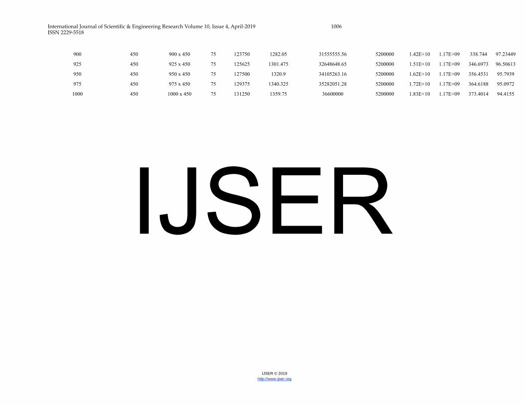
GEOMETRICAL PROPERTIES OF I-SECTION NIGERIAN-GROWN AFRICAN BIRCH TIMBER
Depth of Section (mm)
Breadth of flange (mm)
I section (mm)
Thickness (mm)
Area (mm2)
Unit Weight (N/m)
Section Modulus x-x (mm3)
Section Mod. y-y(mm3)
Ixx (mm4)
Iyy (mm4)
rxx
(mm) ryy
(mm)
150 150 150 x 150 20 8200 84.952 370666.6667 150666.6667 27800000 11300000 58.2258 37.12208
100 75 100 x 75 20 4200 43.512 105200 38666.66667 5.26E+06 1.45E+06 35.38899 18.58058
100 100 100 x 100 20 5200 53.872 137800 67400 6.89E+06 3.37E+06 36.40055 25.45735
150 100 150 x 100 20 6200 64.232 257333.3333 68200 1.93E+07 3.41E+06 55.7934 23.45208
175 100 175 x 100 20 6700 69.412 323428.5714 68400 2.83E+07 3.42E+06 64.99139 22.59309
200 100 200 x 100 20 7200 74.592 394000 68800 3.94E+07 3.44E+06 73.97447 21.85813
225 100 225 x 100 20 7700 79.772 468444.4444 69200 5.27E+07 3.46E+06 82.72941 21.19789
250 100 250 x 100 20 8200 84.952 548000 69400 6.85E+07 3.47E+06 91.39835 20.57111
275 100 275 x 100 20 8700 90.132 631272.7273 69800 8.68E+07 3.49E+06 99.88499 20.02872
300 100 300 x 100 20 9200 95.312 720000 70200 1.08E+08 3.51E+06 108.3473 19.53258
150 125 150 x 125 20 7200 74.592 313333.3333 105280 2.35E+07 6.58E+06 57.13046 30.2306
175 125 175 x125 20 7700 79.772 392000 105600 3.43E+07 6.60E+06 66.74238 29.277
200 125 200 x 125 20 8200 84.952 475000 105920 4.75E+07 6.62E+06 76.10968 28.41333
225 125 225 x 125 20 8700 90.132 562666.6667 106080 6.33E+07 6.63E+06 85.29866 27.6056
250 125 250 x 125 20 9200 95.312 653600 106400 8.17E+07 6.65E+06 94.23606 26.88543
275 125 275 x 125 20 9700 100.492 749090.9091 106720 1.03E+08 6.67E+06 103.0464 26.22268
300 125 300 x 125 30 14700 152.292 1146666.667 164800 1.72E+08 1.03E+07 108.1697 26.47037
175 150 175 x 150 30 12450 128.982 592000 228000 5.18E+07 1.71E+07 64.50304 37.06068
200 150 200 x 150 30 13200 136.752 726000 229333.3333 7.26E+07 1.72E+07 74.16198 36.09751
225 150 225 x 150 30 13950 144.522 866666.6667 229333.3333 9.75E+07 1.72E+07 83.60172 35.11374
250 150 250 x 150 30 14700 152.292 1016000 230666.6667 1.27E+08 1.73E+07 92.94867 34.30555
275 150 275 x 150 30 15450 160.062 1170909.091 232000 1.61E+08 1.74E+07 102.0819 33.55911
300 150 300 x 150 30 16200 167.832 1326666.667 232000 1.99E+08 1.74E+07 110.833 32.77307
325 150 325 x 150 30 16950 175.602 1495384.615 233333.3333 2.43E+08 1.75E+07 119.7342 32.13173
350 150 350 x 150 30 17700 183.372 1668571.429 233333.3333 2.92E+08 1.75E+07 128.4413 31.44361
375 150 375 x 150 30 18450 191.142 1850666.667 234666.6667 3.47E+08 1.76E+07 137.1408 30.88575
400 150 400 x 150 30 19200 198.912 2035000 234666.6667 4.07E+08 1.76E+07 145.595 30.2765
IJSER

International Journal of Scientific & Engineering Research Volume 10, Issue 4, April-2019 1005 ISSN 2229-5518
IJSER © 2019 http://www.ijser.org
425 150 425 x 150 30 19950 206.682 2225882.353 236000 4.73E+08 1.77E+07 153.9782 29.78621
450 150 450 x 150 30 20700 214.452 2426666.667 237333.3333 5.46E+08 1.78E+07 162.4094 29.32411
450 175 450 x 175 30 22200 229.992 2720000 316571.4286 6.12E+08 2.77E+07 166.0348 35.32347
450 200 450 x 200 30 23700 245.532 3013333.333 409000 6.78E+08 4.09E+07 169.1378 41.54201
450 225 450 x 225 30 25200 261.072 3311111.111 513777.7778 7.45E+08 5.78E+07 171.9404 47.89207
450 250 450 x 250 30 26700 276.612 3604444.444 632000 8.11E+08 7.90E+07 174.2829 54.39487
450 275 450 x 275 30 28200 292.152 3897777.778 763636.3636 8.77E+08 1.05E+08 176.3499 61.0197
450 300 450 x 300 30 29700 307.692 4191111.111 906666.6667 9.43E+08 1.36E+08 178.1877 67.66923
450 325 450 x 325 30 31200 323.232 4488888.889 1064615.385 1.01E+09 1.73E+08 179.9216 74.4639
450 350 450 x 350 30 32700 338.772 4800000 1228571.429 1.08E+09 2.15E+08 181.7348 81.0859
450 375 450 x 375 30 34200 354.312 5066666.667 1408000 1.14E+09 2.64E+08 182.5742 87.85954
450 400 450 x 400 30 35700 369.852 5377777.778 1605000 1.21E+09 3.21E+08 184.102 94.82403
450 425 450 x 425 30 37200 385.392 5644444.444 1811764.706 1.27E+09 3.85E+08 184.7695 101.7323
450 450 450 x 450 30 38700 400.932 5955555.556 2031111.111 1.34E+09 4.57E+08 186.0788 108.6682
475 450 475 x 450 30 39450 408.702 6400000 2031111.111 1.52E+09 4.57E+08 196.2901 107.6303
500 450 500 x 450 30 40200 416.472 6840000 2031111.111 1.71E+09 4.57E+08 206.2458 106.6216
525 450 525 x 450 30 40950 424.242 7276190.476 2031111.111 1.91E+09 4.57E+08 215.9682 105.6407
550 450 550 x 450 30 41700 432.012 7709090.909 2031111.111 2.12E+09 4.57E+08 225.4758 104.6864
575 450 575 x 450 30 42450 439.782 8173913.043 2031111.111 2.35E+09 4.57E+08 235.2855 103.7574
600 450 600 x 450 50 70000 725.2 13100000 3400000 3.93E+09 7.65E+08 236.9448 104.5398
625 450 625 x 450 50 71250 738.15 13856000 3400000 4.33E+09 7.65E+08 246.5196 103.6187
650 450 650 x 450 50 72500 751.1 14615384.62 3400000 4.75E+09 7.65E+08 255.9634 102.7216
675 450 675 x 450 50 73750 764.05 15407407.41 3400000 5.20E+09 7.65E+08 265.5343 101.8473
700 450 700 x 450 50 75000 777 16171428.57 3404444.444 5.66E+09 7.66E+08 274.712 101.061
725 450 725 x 450 75 110625 1146.075 23034482.76 5155555.556 8.35E+09 1.16E+09 274.7366 102.4006
750 450 750 x 450 75 112500 1165.5 24186666.67 5155555.556 9.07E+09 1.16E+09 283.9405 101.5436
775 450 775 x 450 75 114375 1184.925 25367741.94 5155555.556 9.83E+09 1.16E+09 293.1644 100.7079
800 450 800 x 450 75 116250 1204.35 26500000 5155555.556 1.06E+10 1.16E+09 301.9649 99.89242
825 450 825 x 450 75 118125 1223.775 27636363.64 5155555.556 1.14E+10 1.16E+09 310.6573 99.09645
850 450 850 x 450 75 120000 1243.2 28941176.47 5155555.556 1.23E+10 1.16E+09 320.1562 98.31921
875 450 875 x 450 75 121875 1262.625 30171428.57 5155555.556 1.32E+10 1.16E+09 329.1013 97.55997
IJSER
International Journal of Scientific & Engineering Research Volume 10, Issue 4, April-2019 1006 ISSN 2229-5518
IJSER © 2019 http://www.ijser.org
900 450 900 x 450 75 123750 1282.05 31555555.56 5200000 1.42E+10 1.17E+09 338.744 97.23449
925 450 925 x 450 75 125625 1301.475 32648648.65 5200000 1.51E+10 1.17E+09 346.6973 96.50613
950 450 950 x 450 75 127500 1320.9 34105263.16 5200000 1.62E+10 1.17E+09 356.4531 95.7939
975 450 975 x 450 75 129375 1340.325 35282051.28 5200000 1.72E+10 1.17E+09 364.6188 95.0972
1000 450 1000 x 450 75 131250 1359.75 36600000 5200000 1.83E+10 1.17E+09 373.4014 94.4155
IJSER