compactblocak i/o on remote i/o
TRANSCRIPT

CompactBlock I/O on Remote I/O1791R-4B4P, 1791R-8B8P, 1791R-8V8P, 1791R-16B0, 1791R-0B16P
Technical Data
The 1791R CompactBlock I/O modules contain I/O circuits, removable termination, and a built-in Remote I/O adapter. CompactBlock Remote I/O modules are ideal for applications restricted by space limitations and applications requiring highly distributed I/O blocks close to sensors and actuators.Each Remote I/O node consists of either one base module or one base module and one expansion module. Any expansion module can be coupled with any base module. CompactBlock 1791R consists of only base modules. The expansion modules are part of the CompactBlock 1791D family of products.:
RediSTATION, FLEX I/O, ArmorBlock, DeviceLink, DeviceView, EZLINK, FlexPac and SLC are trademarks of Rockwell Automation.DeviceNet Manager and SoftLogix are trademarks of Rockwell Automation Allen-Bradley, Inc.PLC is a registered trademark of Rockwell Automation.DeviceNet is a trademark of Open DeviceNet Vendor Association (ODVA).
CompactBlock Remote I/O Base Modules and DeviceNet Expansion Modules
• 4 sinking input 4 sourcing output base module (1791R-4B4P)
• 8 sinking input/ 8 sourcing output base module (1791R-8B8P)
• 8 sourcing input/ 8 sinking output base module (1791R-8V8P)
• 16 sinking input base module (1791R-16B0)
• 16 sourcing output base module (1791R-0B16P)
• 16 sinking input expansion module (1791D-16B0X)
• 16 sourcing input expansion module (1791D-16V0X)
• 16 sourcing output expansion module (1791D-0B16PX)
• 16 sinking output expansion module (1791D-0V16PX)

2 CompactBlock I/O on Remote I/O
Important User Information Because of the variety of uses for the products described in this publication, those responsible for the application and use of these products must satisfy themselves that all necessary steps have been taken to assure that each application and use meets all performance and safety requirements, including any applicable laws, regulations, codes and standards. In no event will Rockwell Automation be responsible or liable for indirect or consequential damage resulting from the use or application of these products.
Any illustrations, charts, sample programs, and layout examples shown in this publication are intended solely for purposes of example. Since there are many variables and requirements associated with any particular installation, Rockwell Automation does not assume responsibility or liability (to include intellectual property liability) for actual use based upon the examples shown in this publication.
Allen-BradleyTM publication SGI-1.1, Safety Guidelines for the Application, Installation and Maintenance of Solid-State Control (available from your local Allen-Bradley office), describes some important differences between solid-state equipment and electromechanical devices that should be taken into consideration when applying products such as those described in this publication.
Reproduction of the contents of this copyrighted publication, in whole or part, without written permission of Rockwell Automation, is prohibited.
Overview CompactBlock Remote I/O modules are compatible with PLC®, SLC™ or SoftLogix™ programmable controllers using Remote I/O scanners. All CompactBlock Remote I/O module values are accessible through the data tables of the PLC or SLC programmable controller.Rack addresses on the modules are set using DIP switches located on the module. The switches are read at module power up only.
Features and Benefits
Feature: Benefit:
24V dc device power accommodates broad range of power supplies and multiple voltage levels from the network
NEMA type 3 inputs compatible with a broad range of sensors
self-contained package cost-effective distribution
hardware watchdog function puts outputs in a known state if the microprocessor or crystal fails
I/O block located close to sensors and actuators lower wiring costs
compact size of I/O block module requires no adapter or power supply
panel or DIN rail mounted choice of horizontal or vertical mounting orientation
DIP switches set rack address reduces commissioning time
Removable terminations quick replacement of block without re-wiring
StatusComm
0 1 2 3 4 5 6 7 0 1 2 3 4 5 6 7
CompactBlock I/O1791R-8V8P
8 INPUTS / 8 OUTPUTS - DC POWER
Allen-Bradley
Remote I/O
CompactBlock Remote I/O Module
41673
Publication 1791R-TD001B-EN-P - October 2002

CompactBlock I/O on Remote I/O 3
Typical Configuration This graphic shows how your CompactBlock I/O fits into a typical Remote I/O system.
System Compatibility CompactBlock I/O modules are compatible with PLC, SLC or SoftLogix programmable controllers when used with Remote I/O scanners.
CompactBlock Remote I/O Module Communication
DIP Switch Settings
The 1791R DIP switches are described in the table below
5 6 7
CompactBlock I/O1791R-8V8P
8 INPUTS / 8 OUTPUTS - DC POWER
43321
1756-DHRIO module
SLC Processor with 1747-SN
PLC-5 Processor
VMEbus Master with 6008-SV2R or -SV1R Scanner
PC with 1784-KTS Interface Weight and Rate
Control- Hardy- Mettler Toledo- BLH
DL40 Plus Dataliner
RediPANEL Operator Interface
ControlLogix Gateway
Pneumatic Valveswith embedded Remote I/O capability
- Pneumatics- Festo- Parker Hanifin- SMC
PanelView Operator Terminal
Robots on Remote I/O- Fanuc- Nachi- Kawasaki- ABB- Comau- Kuka- Motoman
1771 I/O I/O Blocks
IMC 123 and S-Class- integrates 3 and 4 axis motion controllers- programmable position- teach pendant- easy path modifications
1771 I/O
Drives
1771 I/O
AutoMax Allen-Bradley Remote I/O Scanner
ABB Ransburg Flotronics
FLEX I/O
Integrated RF Tag Reader for Tracking Production
1791R CompactBlock Remote I/O
Bently Nevada
Vibration
A MCI
A wide range of devices is compatible with our Universal Remote I/O Link, including those shown here.
Resolver PLS
DIP Switch No. Description Starting Quarter
SW1
1 Starting Quarter SW1-2 SW1-2 Module Group
2 Starting Quarter 0 0 0 (1st)
0 1 2 (2nd)
1 0 4 (3rd)
1 1 6 (4th)
Starting Quarter: Position in Rack Address with 1/4 rack size data.
Publication 1791R-TD001B-EN-P - October 2002

4 CompactBlock I/O on Remote I/O
Baud Rates for Your Remote I/O Connection
The baud rate is set before you power up the module using the DIP switches. The baud rate specifications are listed below.
I/O Image Word/Bit Definitions
The smallest portion of a scanners I/O image that can be allocated to a single RIO device is two logical groups or 1/4 logical rack. A device’s starting group must begin at even group numbers (0, 2, 4, or 6). See your scanner documentation for further details.All combinations of 1791R base and expansion modules will fit in the space allocated by 1/4 logical rack.
DIP Switch No. Description
SW1
3 Rack Address
See table of Rack Addresses in the CompactBlock Distributed I/O on Remote I/O installation instructions, publication no., 1791R-IN001.
4 Rack Address
5 Rack Address
6 Rack Address
7 Rack Address
8 Rack Address
SW2
1 Comm Rate 00=57.6K 01=115.2K10=230.4K 11=230.4K2 Comm Rate
3 N/A
4 Hold Last State Hold Last State Output Reset
5 Processor Restart/Lockout Lockout Restart
6 Last I/O Last Rack Not Last Rack
7 Filter Speed Setting 00=2ms 10=4ms01=8ms 11=16ms8 Filter Speed Setting
Rack Address (6 bit): Position in scanner data mapping.
Baud Rate Cable Length
57.6KBPS 3048m
115.2KBPS 1524m
230.4KBPS 762m
Publication 1791R-TD001B-EN-P - October 2002

CompactBlock I/O on Remote I/O 5
Removable Terminal Block The CompactBlock Remote I/O modules come equipped with a removable terminal block (RTB) which allows for easy module replacement without rewiring.
Indicators The CompactBlock Remote I/O module has the following indicators:• Status indicator - base only• Comm indicator - base only• I/O status indicators - base and expansion
VDC
VDC
GND
GNDNotUsed
IN0IN2
IN4IN6
IN7IN5
IN3IN1
IN8IN10 IN12 IN14
IN15
IN13
IN11
IN9
StatusCommRemote I/O
01
23
45
67
01
23
45
67
RIO
Retaining Screw
Retaining Screw
43106
Status Indicator
Indication: Status:
Off No power
Red Hardware or software error, power is low
Green Normal operation
Flashing Red Comm failure 1*
Flashing Red/Orange Expansion error
*1 Comm fail = communication cable disconnected, 100ms between valid frames, no more than 255 valid frames between valid frames addressed to module, 20ms idle time exceeded.
**2 COMM and STATUS will alternately flash when processor restart lockout is selected, a fault has occurred and the processor is communicating with the module.
Comm Status Indicator
Indication: Status:
Off Communication not established
Green Communication established
Flashing Green Processor in Program mode
I/O Status Indicators
Function: LED Color: Module Illumination: Condition:
Outputs Each output: Yellow
NoneYellow
Output not energizedOutput energized
Inputs Each Input: Yellow
NoneYellow
No valid inputValid input
Publication 1791R-TD001B-EN-P - October 2002

6 CompactBlock I/O on Remote I/O
Power Supply Requirements Two sets of VDC+ and GND power pins are located on each terminal (one for each bank of 8 points) except on the 1791R-4B4P module. Input and Output wiring use up to 14AWG (2mm2) stranded (Cu) with 3/64 inch insulation.
Mounting Most CompactBlock Remote I/O base and expansion modules can be mounted directly to a panel or on a DIN rail.
The following graphic shows the base and expansion modules mounting dimensions. Modules can be mounted vertically or horizontally.
Base and expansion modules can be mounted side-by-side. The modules can also be mounted one on top of the other by using the optional longer cable, 1791D-15CMCBL. The following graphic shows a base module connected to an expansion module.
01
23
45
67
01
23
45
67Compact
1791R-8V8P
8 INPUTS / 8 OUTPUTS . DC POWER
Allen-Bradley
Remote I/ORIO
Comm
Status
Block I/O
I/O Status Indicators
43279
Status Indicator
Comm Indicator
StatusNetwork
0 1 2 3 4 5 6 7 0 1 2 3 4 5 6 7
CompactBlock I/OAllen-Bradley
Module
Status
Panel mount - front view
DIN rail mount- side view
Use a standard screwdriverto pull down the locking tab,then push the module ontothe DIN rail.
IMPORTANT Currently, these expansion blocks must be DIN rail mounted to meet our specifications:
• 1791D-16B0X• 1791D-16V0X• 1791D-0B16PX• 1791D-0V16PX
These expansion blocks cannot be panel mounted.
Base Module Expansion Module141 mm 5.55 in
41 mm 1.6 in
104 mm 4.09 in
41 mm 1.6 in
30358
25 mm1 in
Expansion covers
Publication 1791R-TD001B-EN-P - October 2002
CompactBlock I/O on Remote I/O 7
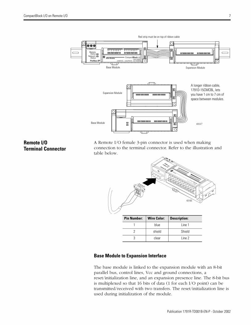
Remote I/O Terminal Connector
A Remote I/O female 3-pin connector is used when making connection to the terminal connector. Refer to the illustration and table below.
Base Module to Expansion Interface
The base module is linked to the expansion module with an 8-bit parallel bus, control lines, Vcc and ground connections, a reset/initialization line, and an expansion presence line. The 8-bit bus is multiplexed so that 16 bits of data (1 for each I/O point) can be transmitted/received with two transfers. The reset/initialization line is used during initialization of the module.
StatusNetwork
Profibus DP
Module
Status
0 1 2 3 4 5 6 7
CompactBlock I/O1791P-8V8P
8 INPUTS / 8 OUTPUTS - DC POWER
Allen-Bradley
0 1 2 3 4 5 6 7
Red strip must be on top of ribbon cable
A longer ribbon cable, 1791D-15CMCBL, lets you have 1 cm to 7 cm of space between modules.
43117
Base Module Expansion Module
Base Module
Expansion Module
Pin Number: Wire Color: Description:
1 blue Line 1
2 shield Shield
3 clear Line 2
01
23
45
67
01
23
45
67Compact
1791R-8V8P
8 INPUTS / 8 OUTPUTS . DC POWER
Allen-Bradley
Remote I/ORIO
Comm
Status
Block I/O
43105
Publication 1791R-TD001B-EN-P - October 2002

8 CompactBlock I/O on Remote I/O
The presence line is used for the detection of an expansion module at power up and for a period of each data transfer. Module ID is read over this bus at power up. 1791R modules supply expansion power via expansion bus as follows:
– Expansion power voltage - 5Vdc
– Expansion power current - 100mA
Power the Module
Power requirements for the CompactBlock Remote I/O module are illustrated below.
Specific Module Information The remainder of this publication contains specification information for each CompactBlock Remote I/O module. Refer to the table below for information about a specific module.
Related Publications Refer to the following publications for more information about the CompactBlock Remote I/O modules.
Pin Number Name
1 Com (24V dc return)
2 Gnd (Field ground)
3 +24V dc
Module power connector
43108
COMGND
+24V
For information about: See page:
Remote I/O Base and Expansion Modules General Specifications 9
16 sinking input base module (1791R-16B0) and Expansion Modules 10
4 sinking input/ 4 sourcing output base module (1791R-4B4P) and Expansion Modules 11
8 sinking input / 8 sourcing output base module (1791R-8B8P) and Expansion Modules 12
8 sourcing input/ 8 sinking output base module (1791R-8V8P) and Expansion Modules 13
16 sourcing output base module (1791R-0B16P) and Expansion Modules 14
16 sinking input expansion module (1791D-16B0X) 15
16 sourcing input expansion module (1791D-16V0X) 16
16 sourcing output expansion module (1791D-0B16PX) 17
16 sourcing output expansion module (1791D-0V16PX) 18
Title: Publication Number:
1791D CompactBlock I/O Product Profile 1791D-PP002
CompactBlock Distributed I/O on Remote I/O Installation Instructions 1791R-IN001
Publication 1791R-TD001B-EN-P - October 2002

CompactBlock Remote I/O General Specifications 9
General Specifications
The following specifications apply for all CompactBlock Remote I/O modules and expansion modules.
General Specifications
IsolationAuxiliary I/O power to RIOI/O group-to-groupI/O group-to-RIO
Type tested to 500V ac for 60 secondsType tested to 500V ac for 60 secondsType tested to 500V ac for 60 seconds
IsolationAuxiliary I/O power to RIOI/O group-to-groupI/O group-to-RIO
Type tested to 500V ac for 60 secondsType tested to 500V ac for 60 secondsType tested to 500V ac for 60 seconds
RIO Power: Voltage Current
18 - 26.4V dc250mA maximum (with expansion)
Expansion Power: VoltageCurrent
5V dc100mA
Auxiliary Power Inputs: Voltage Current
10-30V dc88mA each group of 8
Auxiliary Power Outputs: Voltage Current
10-30V dc4A each group of 8
Base Module Dimensions 150mm X 50mm X 38mm5.91in X 1.97in X 1.5in
Expansion Module Dimensions 115mm X 50mm X 38mm4.4in X 1.97in X 1.5in
Field Wiring Tightening Torque 5-7lb-in. (0.5-0.6 Nm)
Operating Temperature IEC 60068-2-1 (Test Ad, Operating Cold),IEC 60068-2-2 (Test Bd, Operating Dry Heat),IEC 60068-2-14 (Test Nb, Operating Thermal Shock):0 to 60°C (32 to 140°F)
Storage Temperature IEC 60068-2-1 (Test Ab, Un-packaged Non-operating Cold),IEC 60068-2-2 (Test Bb, Un-packaged Non-operating Dry Heat),IEC 60068-2-14 (Test Na, Un-packaged Non-operating Thermal Shock):–40 to 85°C (–40 to 185°F)
Relative Humidity IEC 60068-2-30 (Test Db, Un-packaged Non-operating Damp Heat):5-95% non-condensing
Shock IEC60068-2-27 (Test Ea, Unpackaged Shock):Operating 30gNon-operating 50g
Vibration IEC60068-2-6 (Test Fc, Operating):5g @ 10-500Hz
Conductors Wire Size
Category
14 gauge (2mm2) stranded maximum3/64 inch insulation maximum21, 2
ESD Immunity IEC 61000-4-2:6kV contact discharge8kV air discharge
Radiated RF Immunity IEC 61000-4-3:10V/m with 1kHz sine-wave 80%AM from 80MHz to 1000MHz10V/m with 200Hz 50% Pulse 100%AM at 900Mhz
EFT/B Immunity IEC 61000-4-4:±2kV at 5kHz on signal ports±2kV at 5kHz on communications ports
Surge Transient Immunity IEC 61000-4-5:±1kV line-line(DM) and ±2kV line-earth(CM) on signal ports±2kV line-earth(CM) on shielded ports
General Specifications
Conducted RF Immunity IEC 61000-4-6:10Vrms with 1kHz sine-wave 80%AM from 150kHz to 80MHz
Emissions CSPR 11:Group 1, Class A
Certifications:(when product is marked)
c-UL-us UL Listed Industrial Control Equipment, certified for US and Canada
c-UL-us UL Listed for Class I, Division 2 Group A,B,C,D Hazardous
Locations, certified for U.S. and Canada
CE3 European Union 89/336/EEC EMC Directive, compliant with:EN 50081-2; Industrial EmissionsEN 50082-2; Industrial ImmunityEN 61326; Meas./Control/Lab., Industrial Requirements61000-6-2; Industrial Immunity
C-Tick3 Australian Radiocommunications Act, compliant with:AS/NZS 2064; Industrial Emissions
Enclosure Meets IP20
1. You use this conductor category information for planning conductor routing as described in the system level installation manual.
2. See publication 1770-4.1, “Programmable Controller Wiring and Grounding Guidelines.”
3. See the Product Certification link at www.ab.com for Declarations of Conformity, Certificates, and other certification details.
Publication 1791R-TD001B-EN-P - October 2002

10 16 Sinking Input Base Module 1791R-16B0 CompactBlock Remote I/O
16 Sinking Input Base Module 1791R-16B0 and Expansion Modules
Use the DIP switches to set the baud rate before you power up the module.
Input Wiring Diagram - 1791R-16B0 and 1791D-16B0X Modules
1791R-16B0 I/O images are below.
Specifications
+
_
Simplified Schematic
Input
24V dc
OptoIsolation
System Circuitry
Input Indication LED (Logic)
GND42501
1791R-16B0
17
16
15
14 13 12 11
10 7 6 5 4 3 2 1 0
Input Image
I15
I14
I13
I12
I11
I10
I9
I8
I7
I6
I 5
I4
I3
I2
I1
I0
Input Image
Reserved
Output Image
Reserved
Output Image
Reserved
GND
IN 0 IN 2
+
IN 8IN 6
IN 1 IN 3
IN 4
IN 5 IN 7
IN 10
IN 9
IN 12 IN 14
IN 11 IN 15IN 13GND
-
41671
VDC VDCNot Used
1791R-16B0 with 1791D-16BOX
17 16 15 14 13 12 11 10 7 6 5 4 3 2 1 0
Input Image
I15
I14
I13
I12
I11
I10
I9
I8
I7
I6
I5
I4
I3
I2
I1
I0
Input Image
ExI
15
EX I 14
EX I 13
EX I 12
EX I 11
EX I 10
EX I 9
EX I 8
EX I 7
EXI 6
EX I 5
EX I 4
EX I 3
EX I 2
EX I 1
EX I 0
Output Image
Reserved
Output Image
Reserved
1791R-16B0 with 1791D-0B16PX
17 16 15 14 13 12 11
10 7 6 5 4 3 2 1 0
Input Image
I15
I14
I13
I12
I11
I10
I9
I8
I7
I6
I5
I4
I3
I2
I1
I0
Input Image
Reserved
Output Image
ExO 15
ExO 14
ExO 13
ExO 12
ExO 11
ExO 10
ExO 9
ExO 8
ExO 7
ExO 6
ExO 5
ExO 4
ExO 3
ExO 2
ExO 1
ExO 0
Output Image
Reserved
1791R-16B0 16 Sinking Input Specifications
Inputs per block groups of 4 or 8
Off-state Voltage 5V dc maximum
On-state Voltage 30V dc @ 40×C maximum25V dc @ 60×C maximum10V dc minimum
Off-state Current 1.5mA minimum
On-state Current 11mA @ 30V dc maximum2mA @ 10V dc minimum
Publication 1791R-TD001B-EN-P - October 2002

CompactBlock Remote I/O
Publication 1791R-TD001B-EN-P - October 2002
4 Sinking Input/4 Sourcing Output Base Module 1791R-4B4P 11
4 Sinking Input/4 Sourcing Output Base Module 1791R-4B4P and Expansion Modules
Use the DIP switches to set the baud rate before you power up the module.
Wiring Diagram - 1791R-4B4P Base Module
1791R-4B4P I/O images are below.
Specifications
+
_
+
–
Output Simplified Schematic
Output24V dc
Load
Opto Isolation
System Circuitry
Output Indication LED (Logic)
V dc
Protected Output Device
Gnd
Input Simplified Schematic
GND
24V dc
Opto Isolation
System Circuitry
Input Indication LED (Logic)
Input
42500
1791R-4B4P
17 16
15
14
13
12
11
10 7 6 5 4 3 2 1 0
Input Image
Reserved I 3
I 2
I 1
I 0
Input Image
Reserved
Output Image
Reserved O 3
O 2
O 1
O 0
Output Image
Reserved
1791R-4B4P with1791D-0B16PX
17
16
15
14
13
12
11
10 7 6 5 4 3 2 1 0
Input Image
Reserved I 3 I2
I1
I0
Input Image
Reserved
Output Image
EX O 11
EX O 10
EX O 9
EX O 8
EX O7
EX O 6
EX O 5
EX O 4
EX O3
EX O 2
EX O 1
EX O 0
O 3
O 2
O 1
O 0
Output Image
Reserved EXO 15
EX O 14
EXO 13
EX O 12
IN 0 VDC OUT 0VDC
IN 1 VDC
IN 2
IN 3 VDC
GND
OUT 1
OUT 2 GND
GND GNDOUT 3
42344
VDC VDC
GND GND
Not Used
Load+
-
+
-
1791R-4B4P with 1791D-16BOX
17
16 15
14
13
12 11
10 7 6 5 4 3 2 1 0
Input Image
EX I 11
EX I10
EX I 9
EX I 8
EX I 7
EXI 6
EX I 5
EX I 4
EX I 3
EX I 2
EX I 1
EX I 0
I3
I2
I1
I0
Input Image
Reserved ExI
15
EX I 14
EXI 13
EX I 12
Output Image
Reserved O 3
O 2
O 1
O 0
Output Image
Reserved
1791R-4B4P Sinking Input Specifications
Inputs per block groups of 4 or 8
Off-state Voltage 5V dc maximum
On-state Voltage 30V dc @ 40×C maximum25V dc @ 60×C maximum10V dc minimum
Off-state Current 1.5mA minimum
On-state Current 11mA @ 30V dc maximum2mA @ 10V dc minimum
1791R-4B4P Sourcing Output Specifications
Outputs per block groups of 4 or 8
On-state Voltage Range 10 - 30V dc
On-state Voltage Drop 0.5V dc @ rated current
On-state Current 0.5A maximum
Off-state Leakage 1.0mA maximum
Module Current (per output) 0.5A maximum
Surge Current - for 10 mS repeatable every 2 S
1.0A maximum
Indicators Status - red/green/orangeComm - greenI/O - yellow
Communication Rate 57.6Kbps @ 3048m (10000ft) 115.2Kbps @ 1524m (5000ft) 230.4Kbps @ 762m (2500ft)

Publication 1791R-TD001B-EN-P - October 2002
12 8 Sinking Input/8 Sourcing Output Base Module 1791R-8B8P CompactBlock Remote I/O
8 Sinking Input/8 Sourcing Output Base Module 1791R-8B8P and Expansion Modules
Use the DIP switches to set the baud rate before you power up the module.
Wiring Diagram - 1791R-8B8P Base Module
1791R-8B8P I/O images are below.
Specifications
+
_
+
–
Output Simplified Schematic
Output24V dc
Load
Opto Isolation
System Circuitry
Output Indication LED (Logic)
V dc
Protected Output Device
Gnd
Input Simplified Schematic
Input
24V dc
Opto Isolation
System Circuitry
Input Indication LED (Logic)
V dc
42500
1791R-8B8P
17
16 15
14
13 12
11
10 7 6 5 4 3 2 1 0
Input Image
Reserved I 7
I 6
I 5
I 4
I 3
I 2
I 1
I 0
Input Image
Reserved
Output Image
Reserved O 7
O 6
O 5
O 4
O 3
O 2
O 1
O 0
Output Image
Reserved
1791R-8B8P with 1791D-16BOX
17 16 15 14
13
12
11
10 7 6 5 4 3 2 1 0
Input Image
EX I7
EXI6
EXI5
EX I4
EX I3
EXI2
EXI1
EX I0
I7
I6
I5
I 4
I3
I2
I1
I0
Input Image
Reserved ExI
15
EX I 14
EX I 13
EX I 12
EX I11
EX I10
EXI 9
EXI 8
Output Image
Reserved O7
O6
O 5
O 4
O 3
O 2
O1
O0
Output Image
Reserved
VDC
GND
IN 0 IN 2
+
OUT 0IN 6
IN 1 IN 3
IN 4
IN 5 IN 7
OUT 2
OUT 1
OUT 4 OUT 6
OUT 3 OUT 7OUT 5
VDC
GND
-+
-
41672
Load
Not Used
1791R-8B8P with 1791D-0B16PX
17
16
15
14
13
12
11
10 7 6 5 4 3 2 1 0
Input Image
Reserved I7
I 6
I 5
I 4
I3
I2
I1
I0
Input Image
Reserved
Output Image
EX O 7
EX O 6
EX O 5
EX O4
EX O3
EX O2
EX O1
EX O0
O7
O 6
O 5
O 4
O 3
O2
O1
O0
Output Image
Reserved EXO 15
EX O 14
EXO 13
EX O 12
EX O 11
EX O 10
EX O9
EX O8
1791R-8B8P Sinking Input Specifications
Inputs per block groups of 4 or 8
Off-state Voltage 5V dc maximum
On-state Voltage 30V dc @ 40×C maximum25V dc @ 60×C maximum10V dc minimum
Off-state Current 1.5mA minimum
On-state Current 11mA @ 30V dc maximum2mA @ 10V dc minimum
1791R-8B8P Sourcing Output Specifications
Outputs per block groups of 4 or 8
On-state Voltage Range 10 - 30V dc
On-state Voltage Drop 0.5V dc @ rated current
On-state Current 0.5A maximum
Off-state Leakage 1.0mA maximum
Module Current (per output) 0.5A maximum
Surge Current - for 10 mS repeatable every 2 S
1.0A maximum
Indicators Status - red/green/orangeComm - greenI/O - yellow
Communication Rate 57.6Kbps @ 3048m (10000ft) 115.2Kbps @ 1524m (5000ft) 230.4Kbps @ 762m (2500ft)

CompactBlock Remote I/O
Publication 1791R-TD001B-EN-P - October 2002
8 Sourcing Input/8 Sinking Output Base Module 1791R-8V8P 13
8 Sourcing Input/8 Sinking Output Base Module 1791R-8V8P and Expansion Modules
Use the DIP switches to set the baud rate before you power up the module.
Wiring Diagram - 1791R-8V8P Base Module
The 1791R-8V8P I/O images are below.
Specifications
+
_
+
–
Output Simplified Schematic
Output24V dc
Load
Opto Isolation
System Circuitry
Output Indication LED (Logic)
V dc
Protected Output Device
Gnd
Input Simplified Schematic
Input
24V dc
Opto Isolation
System Circuitry
Input Indication LED (Logic)
V dc
42500
1791R-8V8P
17 16 15 14 13 12 11 107 6 5 4 3 2 1 0
Input Image
Reserved I7
I 6
I 5
I4
I3
I2
I1
I 0
Input Image
Reserved
Output Image
Reserved O7
O6
O5
O4
O3
O2
O1
O0
Output Image
Reserved
1791R-8V8P with 1791D-16VOX
17
16
15
14
13
12
11
10 7 6 5 4 3 2 1 0
Input Image
EX I7
EXI 6
EXI 5
EXI4
EXI3
EXI2
EXI1
EXI0
I7
I6
I5
I 4
I3
I2
I1
I 0
Input Image
Reserved EXI
15
EX I 14
EXI 13
EX I 12
EX I 11
EX I 10
EXI 9
EXI8
Output Image
Reserved O7
O6
O 5
O 4
O 3
O 2
O1
O0
Output Image
Reserved
IN 0 IN 2 OUT 0IN 6
IN 1 IN 3
IN 4
IN 5 IN 7
OUT 2
OUT 1
OUT 4 OUT 6
OUT 3 OUT 7OUT 5
42346
VDC VDC
GND GND
Not Used
Load+
- +
-
1791R-8V8P with 1791D-0V16PX
17
16
15
14
13
12
11
10 7 6 5 4 3 2 1 0
Input Image
Reserved I7
I 6
I 5
I 4
I3
I2
I1
I0
Input Image
Reserved
Output Image
EX O7
EXO 6
EXO 5
EXO4
EXO3
EXO2
EXO1
EXO0
O7
O 6
O 5
O 4
O 3
O2
O1
O0
Output Image
Reserved EXO 15
EXO 14
EXO 13
EXO 12
EX O 11
EX O 10
EXO 9
EXO8
1791R-8V8B Sourcing Input Specifications
Inputs per block groups of 4 or 8
Off-state Voltage 5V dc maximum
On-state Voltage 30V dc @ 40×C maximum25V dc @ 60×C maximum10V dc minimum
Off-state Current 1.5mA minimum
On-state Current 11mA @ 30V dc maximum2mA @ 10V dc minimum
1791R-8V8B Sinking Output Specifications
Outputs per block groups of 4 or 8
On-state Voltage Range 10 - 30V dc
On-state Voltage Drop 0.5V dc @ rated current
On-state Current 0.5A maximum
Off-state Leakage 1.0mA maximum
Module Current (per output) 0.5A maximum
Surge Current - for 10 mS repeatable every 2 S
1.0A maximum
Indicators Status - red/green/orangeComm - greenI/O - yellow
Communication Rate 57.6Kbps @ 3048m (10000ft) 115.2Kbps @ 1524m (5000ft) 230.4Kbps @ 762m (2500ft)

Publication 1791R-TD001B-EN-P - October 2002
14 16 Sourcing Output Base Module 1791R-0B16P CompactBlock Remote I/O
16 Sourcing Output Base Module 1791R-0B16P and Expansion Modules
Use the DIP switches to set the baud rate before you power up the module.
Output Wiring Diagram - 1791R-0B16P and 1791D-0B16PX Modules.
1791R-OB16P I/O images are below.
Specifications
+
–
Simplified Schematic
Output24V dc
Load
OptoIsolation
System Circuitry
Output Indication LED (Logic)
V dc
Protected Output Device
Gnd 42502
1791R-0B16P
17 16
15
14
13
12
11 10 7 6 5 4 3 2 1 0
Input Image
Reserved
Input Image
Reserved
Output Image
O 15
O 14
O 13
O 12
O11
O 10
O 9
O 8
O7
O6
O5
O 4
O3
O2
O1
O0
Output Image
Reserved
1791R-0B16P with 1791D-0B16PX
17
16
15
14 13
12 11
10 7 6 5 4 3 2 1 0
Input Image
Reserved
Input Image
Reserved
Output Image
O 15
O 14
O 13
O 12
O 11
O 10
O9
O 8
O7
O6
O 5
O 4
O3
O2
O1
O0
Output Image
EXO 15
EXO 14
EXO 13
EXO 12
EXO 11
EX O 10
EXO 9
EXO8
EX O7
EXO6
EXO5
EXO4
EXO3
EXO2
EXO1
EXO0
VDC
GND
OUT 0 OUT 2
+
OUT 8OUT 6
OUT 1 OUT 3
OUT 4
OUT 5 OUT 7
OUT 10
OUT 9
OUT 12 OUT 14
OUT 11 OUT 15OUT 13
VDC
GND
-
Load
41669
Not Used
1791R-0B16P with 1791D-16B0X
17
16
15
14 13
12 11
10 7 6 5 4 3 2 1 0
Input Image
EXI
15
EXI 14
EXI 13
EXI 12
EXI 11
EX I 10
EXI 9
EXI8
EX I7
EXI6
EXI5
EXI4
EXI3
EXI2
EXI1
EXI0
Input Image
Reserved
Output Image
O 15
O 14
O 13
O 12
O 11
O 10
O9
O 8
O7
O6
O 5
O 4
O3
O2
O1
O0
Output Image
Reserved
16 Sourcing Output Module (1791R-0B16P) Specifications
Outputs per block groups of 4 or 8
On-state Voltage Range 10 - 30V dc
On-state Voltage Drop 0.5V dc @ rated current
On-state Current 0.5A maximum
Off-state Leakage 1.0mA maximum
Module Current (per output) 0.5A maximum
Surge Current - for 10 mS repeatable every 2 S
1.0A maximum
Indicators Status - red/green/orangeComm - greenI/O - yellow
Communication Rate 57.6Kbps @ 3048m (10000ft) 115.2Kbps @ 1524m (5000ft) 230.4Kbps @ 762m (2500ft)

CompactBlock Remote I/O
Publication 1791R-TD001B-EN-P - October 2002
16 Sinking Input Expansion Module 1791D-16B0X 15
16 Sinking Input Expansion Module 1791D-16B0X
The 1791D-16BOX CompactBlock expansion module I/O can be used with the 1791 Remote I/O modules.
Wiring Connections
Input Wiring Diagram for 1791D-16B0X Expansion Module
Specifications
+
_
Simplified Schematic
Input
24V dc
OptoIsolation
System Circuitry
Input Indication LED (Logic)
GND42501
+
-
GND
IN 0 IN 2 IN 8IN 6
IN 1 IN 3
IN 4
IN 5 IN 7
IN 10
IN 9
IN 12 IN 14
IN 11 IN 15IN 13GND
VDC VDCNot
Used
41671
Sinking Inputs Max
Inputs per Block 2 groups of 8
Off-state Voltage 5V dc
On-state Voltage 30V dc @ 40°C 24V dc @ 60°C 10V dc minimum
Off-state Current 1.5mA @ 5V dc
On-state Current 11mA @ 30V dc

Publication 1791R-TD001B-EN-P - October 2002
16 16 Sourcing Input Expansion Module 1791D-16V0X CompactBlock Remtoe I/O
16 Sourcing Input Expansion Module 1791D-16V0X
The 1791D-16VOX CompactBlock expansion module I/O can be used with the 1791 Remote I/O modules.
Wiring Connections
Input Wiring Diagram for 1791D-16V0X Expansion Module
Specifications
Simplified Schematic
Input
24V dc
+
_
OptoIsolation
System Circuitry
Input Indication LED (Logic)
V dc
41886
+
-
VDC
GND
IN 0 IN 2 IN 8IN 6
IN 1 IN 3
IN 4
IN 5 IN 7
IN 10
IN 9
IN 12 IN 14
IN 11 IN 15IN 13
VDC
GND
41670
Not Used
Sourcing Inputs Max
Inputs per Block 2 groups of 8
Off-state Voltage 5V dc
On-state Voltage 30V dc @ 40°C 24V dc @ 60°C 10V dc minimum
Off-state Current 1.5mA @ 5V dc
On-state Current 11mA @ 30V dc

CompactBlock Remote I/O
Publication 1791R-TD001B-EN-P - October 2002
16 Sourcing Output Expansion Module 1791D-0B16PX 17
16 Sourcing Output Expansion Module 1791D-0B16PX
The 1791D-0B16PX CompactBlock expansion module I/O can be used with the 1791 Remote I/O modules.
Wiring Connections
Output Wiring Diagram for 1791D-0B16PXExpansion Module
Specifications
+
–
Simplified Schematic
Output24V dc
Load
OptoIsolation
System Circuitry
Output Indication LED (Logic)
V dc
Protected Output Device
Gnd 42502
VDC
GND
OUT 0 OUT 2 OUT 8OUT 6
OUT 1 OUT 3
OUT 4
OUT 5 OUT 7
OUT 10
OUT 9
OUT 12 OUT 14
OUT 11 OUT 15OUT 13
VDC
GND
Load
Not Used
41669
+
_
Sourcing Outputs
Outputs per Block 2 groups of 8
On-state Voltage Range 10 - 30V dc
On-state Voltage Drop 0.5V dc @ rated current
On-state Current 0.5A maximum
Off-state Leakage 1.0mA maximum
Module Current (all outputs) 4.0A maximum
Surge Current - for 10ms, repeatable every 2 s
1.0A maximum

Publication 1791R-TD001B-EN-P - October 2002
18 16 Sourcing Output Expansion Module 1791D-0V16PX CompactBlock Remote I/O
16 Sinking Output Expansion Module 1791D-0V16PX
The 1791D-0V16PX CompactBlock expansion module I/O can be used with the 1791 Remote I/O modules.
Wiring Connections
Output Wiring Diagram for 1791D-0V16PXExpansion Module
Specifications
+
_
Simplified Schematic
Output
24V dc
Load
OptoIsolation
System Circuitry
Output Indication LED (Logic)
V dc
Protected Output Device
Gnd 42503
+
_
VDC
GND
OUT 0 OUT 2 OUT 8OUT 6
OUT 1 OUT 3
OUT 4
OUT 5 OUT 7
OUT 10
OUT 9
OUT 12 OUT 14
OUT 11 OUT 15OUT 13
VDC
Load
GND
Not Used
41726
Sinking Outputs
Outputs per Block 2 groups of 8
On-state Voltage Range 10 - 30V dc
On-state Voltage Drop 0.5V dc @ rated current
On-state Current 0.5A maximum
Off-state Leakage 1.0mA maximum
Module Current (all outputs) 4.0A maximum
Surge Current - for 10ms repeatable every 2 s
1.0A maximum


RediSTATION, FLEX I/O, ArmorBlock, DeviceLink, DeviceView, EZLINK, FlexPac, SLC, DeviceNet Manager and SoftLogix are trademarks of Rockwell Automation, Inc.PLC is a registered trademark of Rockwell Automation, Inc.DeviceNet is a trademark of Open DeviceNet Vendor Association (ODVA).
Publication 1791R-TD001B-EN-P - October 2002 20 PN 957707-93
Supersedes Publication 1791R-TD001A-EN-P - June 2002 Copyright © 2002 Rockwell Automation, Inc. All rights reserved. Printed in the U.S.A