manual fb remote i/o system
TRANSCRIPT

FB Remote I/O SystemHardware
PROCESS AUTOMATION
MANUAL

With regard to the supply of products, the current issue of the following document is ap-plicable: The General Terms of Delivery for Products and Services of the Electrical Indus-
try, published by the Central Association of the Electrical Industry (Zentralverband Elektrotechnik und Elektroindustrie (ZVEI) e.V.) in its most recent version as well as the
supplementary clause: "Expanded reservation of proprietorship"
FB Remote I/O System

FB Remote I/O System
3
1 Introduction................................................................................. 5
1.1 Content of this Document ................................................................... 5
1.2 Target Group, Personnel...................................................................... 5
1.3 Symbols Used ...................................................................................... 6
2 Product Specifications............................................................... 7
2.1 Prerequisites for Operating the Remote I/O Unit .............................. 7
2.2 Introduction .......................................................................................... 7
2.3 System Overview ................................................................................. 8
2.4 Backplanes ........................................................................................... 9
2.4.1 Function............................................................................................. 9
2.4.2 Design and Dimensions..................................................................... 9
2.4.3 Backplane and Module Compatibility............................................... 10
2.5 I/O Modules, Com Units, Bus Termination Modules,
Power Supplies .................................................................................. 11
2.5.1 Function........................................................................................... 11
2.5.2 Design and Dimensions................................................................... 11
2.6 Field Units........................................................................................... 12
2.7 Accessories ........................................................................................ 12
2.7.1 Bus Connection ............................................................................... 12
2.7.2 Field Wiring...................................................................................... 12
2.7.3 Connection Cables .......................................................................... 18
3 Installation................................................................................. 19
3.1 Surrounding Enclosure ..................................................................... 19
3.2 Mounting the Backplane ................................................................... 19
3.3 Connectors ......................................................................................... 19
3.3.1 FB9262BP*...................................................................................... 19
3.4 Maximum Number of I/O Modules.................................................... 24
3.5 Inserting and Removing Modules .................................................... 25
3.6 Field Wiring......................................................................................... 29
3.6.1 I/O modules with front socket........................................................... 31
3.6.2 I/O modules with cable tail ............................................................... 33

4
FB Remote I/O System
3.7 Coding .................................................................................................35
3.8 Line Fault Detection ...........................................................................36
3.9 Cold Junctions in Thermocouples....................................................37
3.10 Line Resistance in Resistance Thermometers ................................38
3.11 Strain Gage Measurement..................................................................39
3.12 Redundancy ........................................................................................39
3.12.1 Basic Principles................................................................................ 39
3.12.2 Media Redundancy .......................................................................... 40
3.12.3 Application Redundancy .................................................................. 40
3.13 Fieldbus Connection..........................................................................41
3.14 Potential Equalization and Shielding................................................43
3.14.1 Interference ...................................................................................... 43
3.14.2 Wiring............................................................................................... 44
3.15 System Expansion..............................................................................45
4 Commissioning......................................................................... 46
4.1 Electrical Testing of Connections.....................................................46
4.2 Configuration ......................................................................................47
4.3 Startup Phase......................................................................................47
5 Operation................................................................................... 48
6 Troubleshooting........................................................................ 49

FB Remote I/O SystemIntroduction
53
69
43
20
16
-07
5
1 Introduction
1.1 Content of this Document
This document contains information required to use the finished device or system in the relevant phases of the product life cycle. This may include information on the following:
Product identification
Delivery, transport, and storage
Mounting and installation
Commissioning and operation
Maintenance and repair
Troubleshooting
Dismounting
Disposal
The documentation comprises the following parts:
This hardware manual
Software manual for the com units in use
Instruction manuals for the components in use
Datasheets for the components in use
In addition, the documentation may comprise the following parts, if applicable:
EC-type-examination certificate
EU declaration of conformity
Attestation of conformity
Certificates
Control drawings
Other documents
1.2 Target Group, Personnel
Responsibility for planning, assembly, commissioning, operation, maintenance, and dismounting lies with the plant operator.
Only appropriately trained and qualified personnel may carry out mounting, installation, commissioning, operation, maintenance, and dismounting of the product. The personnel must have read and understood the instruction manual and the further documentation.
Ensure that you are familiar with the system and its components before use. Read the documentation carefully.
Note!
This document does not replace the instruction manuals for the components in use.
The safety information for the components in use determines the specific safety instructions
that apply to the system. The instruction manuals for the components in use must have been
read and understood.
Note!
For complete information about the components in use, refer to the instruction manuals and
additional documentation available online at www.pepperl-fuchs.com.
53
69
43
20
16
-07
6
FB Remote I/O SystemIntroduction
1.3 Symbols Used
This document contains symbols for the identification of warning messages and of informative messages.
Warning Messages
You will find warning messages, whenever dangers may arise from your actions. It is mandatory that you observe these warning messages for your personal safety and in order to avoid property damage.
Depending on the risk level, the warning messages are displayed in descending order as follows:
Informative Symbols
Action
This symbol indicates a paragraph with instructions. You are prompted to perform an action or a sequence of actions.
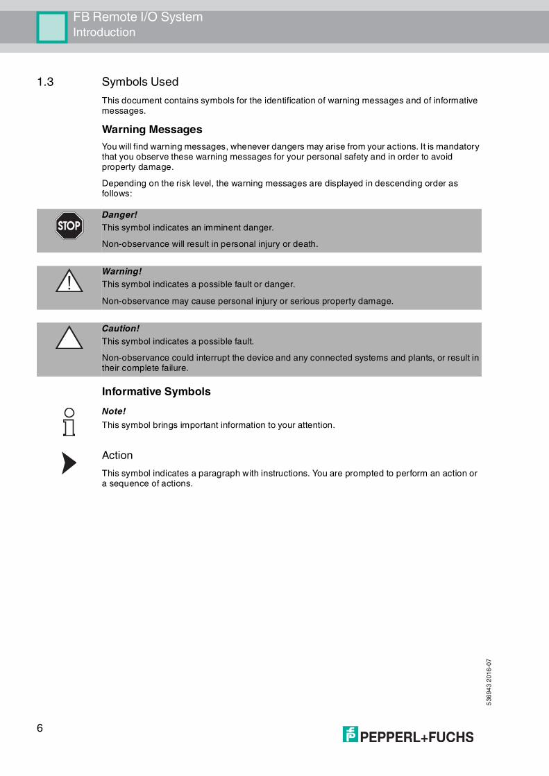
Danger!
This symbol indicates an imminent danger.
Non-observance will result in personal injury or death.
Warning!
This symbol indicates a possible fault or danger.
Non-observance may cause personal injury or serious property damage.
Caution!
This symbol indicates a possible fault.
Non-observance could interrupt the device and any connected systems and plants, or result in their complete failure.
Note!
This symbol brings important information to your attention.

FB Remote I/O SystemProduct Specifications
53
69
43
20
16
-07
7
2 Product Specifications
2.1 Prerequisites for Operating the Remote I/O Unit
2.2 Introduction
Remote I/O stations are signal modification devices that act as an interface for signals between field devices and process control systems. The individual components, i.e., the I/O modules, com units, bus termination modules, and power supplies, are plugged into the slots on the backplane. The I/O modules, com units, bus termination modules, and power supplies of the FB systems can be replaced during ongoing operation in Zone 1. Com units are available for various standard buses and form the interface between the I/O modules and the process control system. Power supplies are used to power the I/O modules and com units.
The bus systems detailed below are supported.
This manual sets out how to work with the hardware. For information on how to configure the com units and I/O modules, refer to the software manual for the relevant com unit in use.
Note!
Requirements for Equipment Protection Level Gb
The FB remote I/O system may be installed and operated in Zone 1 only if it is installed in a
surrounding enclosure that complies with equipment protection level Gb.
Note!
Certification Required
The FB remote I/O system must be certified by a notified body before commissioning.
Bus system Com unit
PROFIBUS DP/DP-V1 FB8205*, FB8206*, FB8209*
MODBUS RTU FB8207*
MODBUS TCP FB8211*
FOUNDATION fieldbus H1 FB8210*

53
69
43
20
16
-07
8
FB Remote I/O SystemProduct Specifications
2.3 System Overview
Figure 2.1 FB remote I/O system components
1. Surrounding Enclosure
2. Backplane with Ex e terminals for power supply and bus cables
3. Power supply
4. Bus termination module
5. Com unit
6. I/O module with intrinsically safe circuits
7. I/O module with Ex e front connector
8. Cable gland for field lines
9. Cable gland for power supply and bus cables
4 51
8
3 762
9

FB Remote I/O SystemProduct Specifications
53
69
43
20
16
-07
9
2.4 Backplanes
2.4.1 Function
Backplanes are used to hold com units, bus termination modules, power supplies, and I/O modules. Fixed slots are reserved on the backplane for com units, bus termination modules, and power supplies. Slots for I/O modules have equal status, meaning functions can be arranged side by side as required.
2.4.2 Design and Dimensions
The following backplanes can be used as base backplanes or as extension backplanes. Connect the two backplane using backplane connection cable FB9274-300.
FB9262BP10220.0
Redundant configuration with slots for two com units, two bus termination modules, two power supplies
Slots for max. 10 single-width or 5 dual-width I/O modules
For PROFIBUS DP, MODBUS RTU, MODBUS TCP, Ethernet
Figure 2.2 FB9262BP10220.0 dimensions
21
2
511
85

53
69
43
20
16
-07
10
FB Remote I/O SystemProduct Specifications
FB9262BP20220.0
Redundant configuration with slots for two com units, two bus termination modules, two power supplies
Slots for max. 20 single-width or 10 dual-width I/O modules
For PROFIBUS DP, MODBUS RTU, MODBUS TCP, Ethernet
Figure 2.3 FB9262BP20220.0 dimensions
2.4.3 Backplane and Module Compatibility
In principle, FB backplanes are compatible with all FB modules. Single-width I/O modules occupy one slot, while double-width I/O modules occupy two slots. However, please be aware of the following restrictions.
FB9262BP*
Use this backplane with the following power supplies only:
FB9206D
FB9215B2
Temporary Overload of the Power Supply
To avoid an overload of the power supply in the startup phase as a result of increased startup currents, the number of certain I/O modules on the backplane is limited.
Use:
a maximum of 11 single-channel I/O modules of type FB3*, FB4*.Each of these I/O modules consumes 9.09 % of the startup capacity.
or a maximum of eight four-channel I/O modules of type FB3*.Each of these I/O modules consumes 12.5 % of the startup capacity.
21
2
511
85

FB Remote I/O SystemProduct Specifications
53
69
43
20
16
-07
11
2.5 I/O Modules, Com Units, Bus Termination Modules, Power Supplies
2.5.1 Function
I/O modules are signal conditioning devices. Field signals from a hazardous area are prepared for controllers or process control systems in a safe area. The slots for the I/O modules on the backplane have equal status, meaning functions can be arranged side by side as required.
Com units form the interface between the I/O modules and the process control system. A com unit can control up to 46 I/O modules and transfer their signals across various standard buses. The com unit converts the protocol of the bus integrated in the backplane to the protocol of the higher-level bus system.
Bus termination modules prevent the reflection of signals at the end of the bus line. A bus termination module is required in each final station of a bus line.
Power supplies provide power to the I/O modules and the associated com units on a backplane. The slots for com units are mechanically coded on the backplane and marked accordingly.
2.5.2 Design and Dimensions
Both single-width and dual-width modules are available. Com units and power supplies are always dual-width. Bus termination modules are always single-width. I/O modules are single-width or dual-width depending on the model.
Both the I/O modules and the com units and power supplies are equipped with LEDs on the front that display the device status.
The I/O modules have connections on the front to which the relevant field devices are connected. On the back of the I/O modules there is a coding pin that prevents an I/O module from being accidentally inserted into a slot that is intended for a com unit or a power supply.
Figure 2.4 Single-width module dimensions
10
7
13228

53
69
43
20
16
-07
12
FB Remote I/O SystemProduct Specifications
Figure 2.5 Dual-width module dimensions
2.6 Field Units
Field units are enclosure solutions, in which one or more backplanes are preinstalled. The enclosures are either made of glass fiber reinforced polyester or stainless steel and are available in various sizes and versions.
Additional terminal boxes and boxes with grounding bars, which can be provided with a bottom flange, are available for enclosures made of glass fiber reinforced polyester.
More information can be found at www.pepperl-fuchs.com.
2.7 Accessories
2.7.1 Bus Connection
The power supply and the bus cables are wired using the Ex e terminal strip, which is located on the left side of the backplane.
2.7.2 Field Wiring
The following accessories are available for field wiring.
Terminal Blocks
Terminal blocks are wired to the field devices, attached to the front sockets of the I/O modules, and tightened using the side screws. Terminal blocks can come in the form of screw terminals, front screw terminals, or spring terminals. Use blue terminal blocks for intrinsically safe circuits. Use black terminal blocks for non-intrinsically safe circuits that comply with type of protection Ex e.
Screw Terminals
• Blue: LB9107A, LB9113A, LB9124A, LB9125A
Front Screw Terminals
• Blue: LB9117A, LB9118A, LB9119A, LB9127A
Spring terminals
• Blue: LB9107P, LB9115A, LB9116A, LB9126A
• Black: LB9109.E.6.1, LB9109.E.8.1, LB9109.E.8.2
13257
10
7

FB Remote I/O SystemProduct Specifications
53
69
43
20
16
-07
13
Figure 2.6 Screw terminal dimensions
L = 33.3 mm for 6-pin terminals and 40.9 mm for 8-pin terminals
Figure 2.7 Front screw terminal dimensions
L = 33.3 mm for 6-pin terminals and 40.9 mm for 8-pin terminals
Figure 2.8 Spring terminal dimensions
L = 33.3 mm for 6-pin terminals and 40.9 mm for 8-pin terminals
Screw Terminals
Front Screw Terminals
Spring Terminals
15.3 L
11
.1
21.7 L
12
.3
20.8 L
12
.4

53
69
43
20
16
-07
14
FB Remote I/O SystemProduct Specifications
Protective covers
Protective covers are used to protect the wiring to the terminal blocks, so that no bare, conductive parts are exposed. Protective covers are available in black and blue. Use blue protective covers for intrinsically safe circuits. Use black protective covers for non-intrinsically safe circuits that comply with type of protection Ex e.
Protective covers
• Blue: LB9108A, LB9120A
• Black: LB9107.E.6, LB9107.E.8
Figure 2.9 Protective cover dimensions
L = 25.25 mm for protective covers for 6-pin terminals and 32.87 mm for protective covers for 8-pin terminals
Figure 2.10 Dimensions of protective covers for Ex e modules
L = 33.4 mm for protective covers for 6-pin terminals and 40.8 mm for protective covers for 8-pin terminals
Protection covers for intrinsically safe circuits
Protective covers for Ex e modules
14.5L3
9
17 L
16

FB Remote I/O SystemProduct Specifications
53
69
43
20
16
-07
15
Cold junctions
Cold junctions have a prewired Pt100 thermocouple on terminal openings 1 and 2 for numerically correcting the thermoelectric voltage. Cold junctions are available exclusively in blue. Use blue cold junctions for intrinsically safe circuits.
Cold junctions
• Blue: LB9112A
Cold junctions with a protective cover
• Blue: LB9111A
Figure 2.11 Cold junction dimensions
L = 33.3 mm for 6-pin terminals
Figure 2.12 Dimensions of a cold junction with a protective cover
L = 33.3 mm for 6-pin terminals
Cold Junction
Cold Junction with a Protective Cover
16.1 L1
1.1
12
12
14.5L
39
(45
.6)
6.6

53
69
43
20
16
-07
16
FB Remote I/O SystemProduct Specifications
Coding pins
Coding pins provide a unique assignment between I/O modules and terminal blocks or the associated field devices. To do this, the coding pins are pushed into the grooves provided in the front sockets of the I/O modules. This prevents terminal blocks from being accidentally plugged into another I/O module.
Figure 2.13 KF-CP coding pins
Watchdog Plugs
The watchdog plug is used with digital outputs with a feedback input (FB2201B ... FB2213E). The watchdog plug sends the output signal from the I/O module back to its input channel, making it possible to check the function of the I/O module, as well as the communication between the process control system and the I/O module.
Figure 2.14 Block diagram for the LB9180A
KF-CP
LB9180A
Zone 1, 2
LB9180A
1 kΩ
- 5
- 6
4
2,4 kΩ
+
-
+
+
3
2
1

FB Remote I/O SystemProduct Specifications
53
69
43
20
16
-07
17
Resistor Network
Most I/O modules have a line fault detection function that can recognize a lead breakage or a short circuit.
If binary I/O modules are used, for example with a mechanical contact, an additional resistor network must be installed to ensure that the line fault detection function can work correctly. Using the additional resistor network, the electronics can distinguish between a closed switch and a short circuit.
Figure 2.15 Dimensions of the F-NR2-Ex1 resistor network
Figure 2.16 Block diagram of the F-NR2-Ex1 resistor network
F-NR2-Ex1
27
35150
Ø15.5
Zone 1, 2
F-NR2-Ex1
10 kΩ
1.5 kΩ
2-
1+
-
+

53
69
43
20
16
-07
18
FB Remote I/O SystemProduct Specifications
2.7.3 Connection Cables
Com unit connection cable
The com unit connection cable LB9140A establishes a local connection between two com units. If two com units are used in a redundant system, they must be connected using a com unit connection cable via the front socket to enable internal data exchange. The length of com unit connection cable LB9140A is 1 m.
Com unit FB8211* has 2 front sockets. The socket with contacts 1 ... 8 is used to connect the com unit connection cable. The socket with contacts 9 ... 16 serves as a service bus connection.
Com unit FB8210* is not designed for redundancy mode and therefore has no front socket.
Backplane connection cable
Backplane connection cables FB9271* ... FB9274* establish a local connection between a base backplane and an extension backplane. If a base backplane is extended with an extension backplane with additional I/O modules and power supplies, the backplane connection cable ensures data exchange between the com units on the base backplane and the I/O modules on the extension backplane. The length of backplane connection cables FB9271* ... FB9274* is up to 3 m.

FB Remote I/O SystemInstallation
53
69
43
20
16
-07
19
3 Installation
3.1 Surrounding Enclosure
3.2 Mounting the Backplane
Mounting the Backplane
1. Mount the backplane horizontally on a DIN mounting rail.
2. Make sure that the maximum ambient temperature for the components used is not exceeded.
3.3 Connectors
3.3.1 FB9262BP*
The power supply and the bus cables are wired using the Ex e terminal strip, which is located on the left side of the backplane.
Note!
Requirements for Equipment Protection Level Gb
The FB remote I/O system may be installed and operated in Zone 1 only if it is installed in a
surrounding enclosure that complies with equipment protection level Gb.
Note!
Certification Required
The FB remote I/O system must be certified by a notified body before commissioning.
Connection data for the Ex e terminal strip
Rigid conductor cross-section 0.14 mm2 ... 1.5 mm2
Flexible conductor cross-section 0.14 mm2 ... 1.5 mm2
Flexible conductor cross-section with wire end ferrule with no plastic sleeve
0.25 mm2 ... 1.5 mm2
Flexible conductor cross-section with wire end ferrule with plastic sleeve
0.25 mm2 ... 0.5 mm2

53
69
43
20
16
-07
20
FB Remote I/O SystemInstallation
Figure 3.1 Ex e terminal block FB9262BP10220.0, FB9262BP20220.0
Terminal Plug-in jumpers Function
39 Connection between base backplane and extension backplane
38
37
36
35 x
34
33 x
32
31
30
29
28
27
26
25 x
24
23 x
22
21
20
PE15141312PE10987
PE54321
3938373635343332313029282726252423222120191817

FB Remote I/O SystemInstallation
53
69
43
20
16
-07
21
19 x Bus-independent deactivation of the I/O modules
Slots 1 ... 10
18 x
17 Slots 11 ... 20
PE Bus connections Screen
15 PROFIBUS DP,MODBUS RTU: BMODBUS TCP, Ethernet: TX+
14 PROFIBUS DP,MODBUS RTU: AMODBUS TCP,Ethernet: TX-
13 PROFIBUS DP,MODBUS RTU: A (service bus)MODBUS TCP,Ethernet: RX+
12 PROFIBUS DP,MODBUS RTU: B (service bus)MODBUS TCP,Ethernet: RX-
PE Redundant bus connections Screen
10 PROFIBUS DP,MODBUS RTU: BMODBUS TCP, Ethernet: TX+
9 PROFIBUS DP,MODBUS RTU: AMODBUS TCP,Ethernet: TX-
8 PROFIBUS DP,MODBUS RTU: A (service bus)MODBUS TCP,Ethernet: RX+
7 PROFIBUS DP,MODBUS RTU: B (service bus)MODBUS TCP,Ethernet: RX-
PE Power supply PE
5 L(+)
4 N(-)
PE Redundant power supply PE
2 L(+)
1 N(-)
Table 3.1 Terminal designation FB9262BP10220.0, FB9262BP20220.0
Terminal Plug-in jumpers Function

53
69
43
20
16
-07
22
FB Remote I/O SystemInstallation
Use as base or extension backplane
Backplanes FB9262BP10220.0 and FB9262BP20220.0 can be used as base backplanes or extension backplanes. Remove the following plug-in jumpers from the backplanes, which should be used as extension backplanes.
22/23
24/25
32/33
34/35
Connection to the extension backplane
To establish a connection between a base backplane and an extension backplane, connect the following terminals using the backplane connection cable FB9271* ... FB9274*.
Connection between base backplane and extension backplane
Danger!
Risk of Explosion
Accessories that do not meet the requirements for use in hazardous areas can cause explosive mixtures to ignite.
Only use accessories and devices that are approved for use in the respective environment.
Base backplane Extension backplane Color
39 39 Blue
38 38 Red
37 37 Black
36 36 Violet
31 35 Pink
30 23 Red/blue
29 29 Yellow
28 28 Green
27 27 Brown
26 26 White
21 25 Brown/green
20 33 Yellow/brown
16 16 Gray(screen)

FB Remote I/O SystemInstallation
53
69
43
20
16
-07
23
Shutdown input
The bus-independent deactivation of the I/O modules only works for I/O modules equipped with a shutdown input. I/O modules with and without a shutdown input can be installed on the same backplane; however, only the I/O modules that are equipped with a shutdown input are controlled by the bus-independent deactivation.
The shutdown is performed using an external volt-free contact, which is galvanically isolated from other contacts and potentials. This isolation also applies to other contacts on other backplanes, unless there is an interconnection between a base backplane and an extension backplane. When the contact is open, the I/O modules are shut down by a shutdown input.
To use the bus-independent shutdown of I/O modules in slots 1 ... 10, replace plug-in jumper 18/19 with an external volt-free contact.
To use the bus-independent shutdown of I/O modules in slots 11 ... 20, replace plug-in jumper 17/18 with an external volt-free contact.
Power supply connection
The power supply may originate from a central grid. We recommend that you install a mains filter. Then connect the power supply to the appropriate terminals of the basic and extension backplanes.
If you are using a direct current, make sure that the cross-sections of the cables are large enough to keep voltage drops on the supply lines to a minimum. The operating voltage must not fall below 20 V, even if loads are connected (e.g., on valves).
Danger!
Risk of Explosion
Devices that do not meet the requirements for use in hazardous areas can cause explosive mixtures to ignite.
Only use a contact that is approved for use in the respective environment. For installation in Zone 1, use a contact that complies with type of protection Ex e.

53
69
43
20
16
-07
24
FB Remote I/O SystemInstallation
3.4 Maximum Number of I/O Modules
The maximum number of I/O modules that can be installed, taking into account the temperature class, is determined by the permissible power dissipation in the surrounding enclosure. If, in addition to the remote I/O system, other loads are installed, their power consumption may reduce the power available to the remote I/O system.
The power consumption of the I/O modules, com unit, and power supplies can be found in the associated data sheets. For some devices, the data sheet gives the power dissipation in addition to the power consumption. This specifies the power that is converted into heat in the device and is decisive for the calculation of heat in the surrounding enclosure. If the power dissipation is not specified in the data sheet, it can be calculated using the power consumption.
The values in the following tables are maximum values that can be applied if an internal temperature of 60°C is reached at an external temperature of the surrounding enclosure of 40 °C. At an external temperature of 50 °C, the permissible power must be halved.
Permissible power for stainless steel enclosures
Permissible power for plastic enclosures
In comparison to analog outputs, digital outputs surrender a large part of their power consumption to loads in the field. It was therefore determined that a maximum of 40 analog channels can be installed in a base unit, and 40 channels in each extension unit. This can be achieved using 10 four-channel I/O modules, which each have a power consumption of 3 W. With a factor of 0.7 (simultaneity factor), this results in a total power consumption of 21 W. The factor was derived from DIN IEC 60364-7-718, VDE 0100-718:2008-05.
Danger!
Risk of Explosion
Due to excessively high power, the maximum permissible temperature within the enclosure and the maximum permissible surface temperature of the surrounding enclosure may be exceeded.
Perform a heat calculation to determine the maximum number of I/O modules. Do not install additional loads if the maximum permissible number of I/O modules is installed in the surrounding enclosure.
Dimensions of the
surrounding enclosure (mm)
(W x H x D)
Permissible power Pmax (W)
wall mounted
Permissible power Pmax (W)
free standing
350 x 306 x 215 43 54
600 x 400 x 220 75 101
600 x 600 x 220 97 137
700 x 350 x 220 78 105
800 x 800 x 300 176 246
800 x 1000 x 300 206 295
Table 3.2 Permissible power for stainless steel enclosures
Dimensions of the surrounding enclosure
(mm)
(W x H x D) Permissible power Pmax (W)
544 x 271 x 210 34
544 x 407 x 210 43
544 x 544 x 210 53
Table 3.3 Permissible power for plastic enclosures

FB Remote I/O SystemInstallation
53
69
43
20
16
-07
25
FB2202*
A maximum of 20 I/O modules of type FB2202* are permitted per backplane.
FB621*
I/O modules of type FB621* have a booster connection for additional auxiliary energy. To provide additional auxiliary power in the case of an AC voltage supply, additional Ex e power supplies are required, which must be taken into account in the heat calculation if they are housed in the same surrounding enclosure.
3.5 Inserting and Removing Modules
The connector pins on the modules and the female connectors on the backplane form a flameproof enclosure when plugged together. This enables energized I/O modules without a hot work permit to be inserted or removed, provided that all non-intrinsically safe circuits are fitted with covers or protective covers with degree of protection IP30.
Figure 3.2 Bent connector pin
Figure 3.3 Damaged pins with nicks or scratches
Fixed slots are reserved on the backplane for com units, bus termination modules, and power supplies. Com units are equipped with mechanical coding pins on the underside of the enclosure to prevent these modules from being accidentally plugged into the slot of an I/O module.
Slots for I/O modules have equal status, meaning functions can be arranged side by side as required. I/O modules with intrinsically safe circuits and I/O modules with non-intrinsically safe circuits can also be arranged side by side. Please note that a clearance of 50 mm must always be maintained between intrinsically safe and non-intrinsically safe circuits.
Unused slots can be left empty or fitted with place-holder module FB9299B.
Danger!
Risk of Explosion
Bent or damaged pins on modules can generate a spark, which can cause explosive mixtures to ignite.
Never use modules with bent or damaged connector pins. If the connector pins are bent or damaged, replace the module with an intact module. Never repair modules with bent connector pins by yourself.

53
69
43
20
16
-07
26
FB Remote I/O SystemInstallation
1. Power supply
2. Bus termination module
3. Com unit when used as a base backplaneEmpty slot when used as an extension backplane
4. Slots for 10 single-width or 5 dual-width I/O modules
5. Redundant power supply
6. Redundant bus termination module
7. Com unit when used as a base backplaneEmpty slot when used as an extension backplane
8. Slots for 10 single-width or 5 dual-width I/O modules
Slots FB9262BP10220.0
Slots FB9262BP20220.0
1 2 3
5 6 7
4
1 2 3 4 5 6 7 8 9 10
1 2 3
5 6 7 8
1 2 3 4 5 6 7 8 9 10
11 12 13 14 15 16 17 18 19 20
4

FB Remote I/O SystemInstallation
53
69
43
20
16
-07
27
Inserting modules
1. Write down the module types used or other identification codes using labeling strips, which you can stick between the female connectors of the backplane. The labeling strips should be no thicker than normal paper so that the I/O modules engage properly at all times.
Figure 3.4 Backplane labeling
2. Arrange the modules on the backplane from left to right.
3. Push the I/O module into the slot until all the rear catches have snapped into place. The I/O module must engage twice.
Figure 3.5 Inserting the module
The I/O module is now mounted securely to the backplane.
Figure 3.6 Module after insertion in the backplane
Note!
If you use redundant com units, establish a front connection between the primary com unit and
the redundant com unit using com unit connection cable LB9140A before you insert the
redundant com unit into the backplane. This ensures that communication between the com
units begins immediately after the voltage supply is applied.
TAG 1 TAG 2 TAG 3 TAG 4

53
69
43
20
16
-07
28
FB Remote I/O SystemInstallation
Removing modules
1. To release the first catch, position the FB removal tool on the right side of the module. Slide the FB removal tool towards the backplane up to the stop.
Figure 3.7 FB removal tool releases the first rear catch
2. Pull out the module a few millimeters together with the FB removal tool until you begin to feel resistance from the second rear catch.
The first rear catch is released and the module no longer has electrical contact with the backplane.
3. Turn the FB removal tool and place it on the left side of the module. Slide the FB removal tool towards the backplane until the second catch is released.
Figure 3.8 FB removal tool releases the second rear catch
4. Pull the module together with the FB removal tool out of the backplane.
The second rear catch is released and the module is removed from the module slot.
5. If applicable, adjust the information on the labeling strips of the backplane.
Warning!
Risk of Explosion
Forcibly removing modules or using unsuitable tools can damage the module or the backplane, meaning that explosion protection can no longer be guaranteed.
Remove modules only using the corresponding FB removal tool (item number 536628 for single-width modules and item number 536627 for dual-width modules). The FB removal tool requires a two-step removal process.

FB Remote I/O SystemInstallation
53
69
43
20
16
-07
29
3.6 Field Wiring
I/O modules are wired differently depending on the type.
1. Modules with intrinsically safe circuits and front sockets
Field connections can be made to the I/O modules using screw terminals, front screw ter-minals, or spring terminals.
2. Modules with non-intrinsically safe circuits and front sockets
Field connections can be made to the I/O modules using black spring terminals. The spring terminals must be covered with protective covers for Ex e modules.
3. Modules with non-intrinsically safe circuits and cable tails
I/O modules with a cable tail must be connected to separately approved terminals that comply with type of protection Ex e. These terminals must be equipped with a cover with degree of protection IP30.
Use the terminal blocks and protective covers from the range of accessories. See chapter 2.7.2
Please note the following requirements for wires, stranded conductors, and wire end ferrules.
Wires
• Insulation stripping: 9 mm
• Core cross-section (conductor): 0.5 mm2 ... 1.5 mm2
• External diameter (conductor + insulation): 2 mm ... 3 mm
1 2 3
Danger!
Risk of Explosion
A spark can be generated by bare, conductive parts such as loose wire ends, which can cause explosive mixtures to ignite.
Stranded conductors without wire end ferrules must not be used. We recommend using wire end ferrules approved according to DIN 46228-4.If I/O-modules with intrinsically safe circuits and I/O modules with non-intrinsically safe circuits are placed directly next to one another, use wire end ferrules with plastic sleeves.

53
69
43
20
16
-07
30
FB Remote I/O SystemInstallation
Stranded conductors
• Insulation stripping: 9 mm
• Core cross-section for wire end ferrules with plastic sleeve: 0.5 mm2 according to IEC 60228 Class 5 and 6
• Core cross-section for wire end ferrules without plastic sleeve: 0.5 mm ... 1.5 mm2 according to IEC 60228 Class 5 and 6
Figure 3.9 Stranded conductor with wire end ferrule
Danger!
Risk of Explosion
Protective covers for Ex e modules with non-intrinsically safe circuits have defined connected loads.
Do not exceed the maximum electrical connected loads: Umax= 63 V, Imax= 1 A
Danger!
Risk of explosion
Measuring instruments that do not meet the requirements for use in hazardous areas can cause explosive mixtures to ignite.
Only use accessories and devices that are approved for use in the respective environment.
Caution!
Loss of intrinsic safety
Circuits with the Ex i type of protection that have been operated with non-intrinsically safe circuits must no longer be used as circuits with Ex i type of protection.
Use only Ex i-certified measuring instruments in conjunction with Ex i-certified I/O modules.

FB Remote I/O SystemInstallation
53
69
43
20
16
-07
31
3.6.1 I/O modules with front socket
Field connections can be made to the I/O modules using screw terminals, front screw terminals, or spring terminals. Use the terminal blocks and protective covers from the range of accessories. See chapter 2.7.2
Front screw terminals or spring terminals are ideal for performing extensions at a later point or for changing individual field connections, as the plug can remain in the front socket of the I/O module during wiring. These terminals also offer a test pick-off for measuring individual circuits.
Installing field wiring for intrinsically safe circuits
1. The I/O modules are wired differently depending on the type. Wire the terminal blocks to the field devices in accordance with the information in the data sheets for the I/O modules used.
2. Note the permissible core cross-section of the conductor. We recommend that you do not
exceed a conductor cross-section of 0.75 mm2.
3. If you are using stranded conductors, make sure that these stranded conductors are crimped with wire end ferrules.
4. Make sure that conductors are insulated all the way up to the terminal.
5. Use blue terminal blocks/protective covers only.
6. Make sure that the separation distances to non-intrinsically safe circuits are observed.
7. Unused cables and connection lines must be either connected to terminals or securely fixed and isolated.
8. If necessary, you can code the front sockets of the I/O modules and terminals so that the terminals and the associated field devices can be assigned to exactly one front socket. See chapter 3.7
9. Plug the terminals into the front sockets of the corresponding I/O modules and screw the terminals into place using the side screws.
10.Label the connection lines.
Connection data for front screw terminals, screw terminals, and spring terminals
Rigid conductor cross-section 0.14 mm2 ... 1.5 mm2
Flexible conductor cross-section 0.14 mm2 ... 1.5 mm2
Flexible conductor cross-section with wire end ferrule with no plastic sleeve
0.25 mm2 ... 1.5 mm2
Flexible conductor cross-section with wire end ferrule with plastic sleeve
0.25 mm2 ... 0.5 mm2
Danger!
Risk of Explosion
Improperly wired front connections can lead to dangerous mix-ups between intrinsically safe and non-intrinsically safe circuits, which can cause explosive mixtures to ignite.

53
69
43
20
16
-07
32
FB Remote I/O SystemInstallation
Installing field wiring for non-intrinsically safe circuits
Non-intrinsically safe circuits must be covered with protective covers for Ex e modules.
1. The I/O modules are wired differently depending on the type. Wire the terminal blocks to the field devices in accordance with the information in the data sheets for the I/O modules used.
2. Note the permissible core cross-section of the conductor. We recommend that you do not
exceed a conductor cross-section of 0.75 mm2.
3. If you are using stranded conductors, make sure that these stranded conductors are crimped with wire end ferrules.
4. Make sure that conductors are insulated all the way up to the terminal.
5. Use only black terminal blocks of type LB9109.E.6.1, LB9109.E.8.1 and LB9109.E.8.2 and protective covers for Ex e modules of type LB9107.E.6 and LB9107.E.8.
Figure 3.10 Spring terminal with protective cover for Ex e modules
6. Make sure that the separation distances to intrinsically safe circuits are observed.
7. Unused cables and connection lines must be either connected to terminals or securely fixed and isolated.
8. If necessary, you can code the front sockets of the I/O modules and terminals so that the terminals and the associated field devices can be assigned to exactly one front socket. See chapter 3.7
9. Plug the terminals into the front sockets of the corresponding I/O modules and screw the terminals into place using the side screws.
10.Break off the lugs of a protective cover for Ex e modules at the points where the field lines lead into the terminal openings. Unused terminal openings must remain covered by the lugs of the protective cover so that no bare, conductive parts are exposed.
11.Place the adapted protective cover for Ex e modules onto the terminal and screw the protective cover into place using the side screws.
Danger!
Risk of Explosion
If intrinsically safe and non-intrinsically safe circuits are present, protective covers may be removed only when the non-intrinsically safe circuits are de-energized and currentless. This can be achieved by disconnecting the I/O module and activating the field circuits using a multifunction terminal (MFT-*).
All unused terminal openings must be covered. If the field wiring is changed and lines are removed, for which lugs have already been broken off from the protective cover, replace the protective cover with a new one.

FB Remote I/O SystemInstallation
53
69
43
20
16
-07
33
Figure 3.11 Terminal with adapted protective cover for Ex e modules
12.Apply the warning marking Warning - non-intrinsically safe circuits protected by internal cover with degree of protection IP30! so that it is visible on the surrounding enclosure.
13.Label the connection lines.
3.6.2 I/O modules with cable tail
I/O modules with a cable tail must be connected to separately approved terminals that comply with type of protection Ex e. These terminals must be equipped with a cover with degree of protection IP30. The cover ensures that no bare, conductive parts are exposed.
Figure 3.12 Field wiring of an I/O module with 2 cable tails
Installing field wiring for I/O modules with cable tail
The terminals for the field wiring must be equipped with a cover with degree of protection IP30.
1. Install the terminals on a separate DIN mounting rail. Arrange the terminals so that the length of the cable tails is sufficient.
2. Refer to the color coding of the connections from the data sheets for the I/O modules used.
3. Make sure that the separation distances to intrinsically safe circuits are observed.
4. Make sure that conductors are insulated all the way up to the terminal.
Danger!
Risk of Explosion
If intrinsically safe and non-intrinsically safe circuits are present, covers with degree of protection IP30 may be removed only when the non-intrinsically safe circuits are de-energized and currentless. This can be achieved by disconnecting the I/O module and activating the field circuits using a multifunction terminal (MFT-*).

53
69
43
20
16
-07
34
FB Remote I/O SystemInstallation
5. Follow the manufacturer's mounting instructions to install the terminals and the cover.
6. Unused cables and connection lines must be either connected to terminals or securely fixed and isolated.
7. Apply the warning marking Warning - non-intrinsically safe circuits protected by internal cover with degree of protection IP30! so that it is visible on the surrounding enclosure.
8. Label the connection lines.
Color coding for single-width I/O modules
Color coding for dual-width I/O modules
Connection Color
6 Pink
5 Gray
4 Yellow
3 Green
2 Brown
1 White
Left connection Right connection Color
8 16 Red
7 15 Blue
6 14 Pink
5 13 Gray
4 12 Yellow
3 11 Green
2 10 Brown
1 9 White

FB Remote I/O SystemInstallation
53
69
43
20
16
-07
35
3.7 Coding
You can code the front sockets of the I/O modules and terminals so that the terminals and the associated field devices can be assigned to exactly one front socket.
Use coding pins KF-CP.
Coding Connections
1. To code the front socket of an I/O module, insert one or more coding pins into the corre-sponding grooves on the front socket.
2. In order to code the terminal to match the front socket, cut off the plastic lugs from the terminal from those points where coding pins are located in the front socket.
Note that the coding in example 1 and example 2 is not unique. The terminal from example 1 could be accidentally connected to the front socket in example 2. In contrast, the coding in example 1 and example 3 is unique.
Caution!
Danger of incorrect connections
If the coding is not unique, terminals can be accidentally mixed up.
Establish a unique coding so that every terminal fits exactly one front socket.
Example 1 Example 2 Example 3
Terminal
Front socket
53
69
43
20
16
-07
36
FB Remote I/O SystemInstallation
3.8 Line Fault Detection
Most I/O modules have a line fault detection function that can recognize a lead breakage or a short circuit.
If digital I/O modules are used, for example with a mechanical contact, an additional resistor circuit must be installed to ensure that the line fault detection function can work correctly. Using the additional resistor circuit, the electronics can distinguish between a closed switch and a short circuit. See chapter 2.7.2
FB1*03*
If you are using rotational direction monitoring, connect this input to a resistor circuit. The rotational direction input is ignored for devices without rotational direction detection.
FB1*08*, FB1*09*
24 V and 5 V inputs can only be used when line fault detection is disabled.
FB2*
The valve control circuit is monitored by a current pulse. This current pulse is brief enough not to operate a connected valve. If the I/O module is being used with indicator lights or sounders, you can switch off the current pulse for each channel. It is not always possible to monitor the valve circuit when booster valves are used because these valves have a storage capacitor that behaves like a short circuit when the valve is switched off. In such cases, depending on the valve, a 10 kΩ parallel resistor enables line fault detection for booster valves. If line fault detection is still detected when the valve is off, even with the parallel resistor connected, disable the line fault detection function.
The line fault detection function of the analog I/O modules is based on a current measurement. An additional resistor circuit is not required.
For more information, refer to the software manual for the com unit used.
FB Remote I/O SystemInstallation
53
69
43
20
16
-07
37
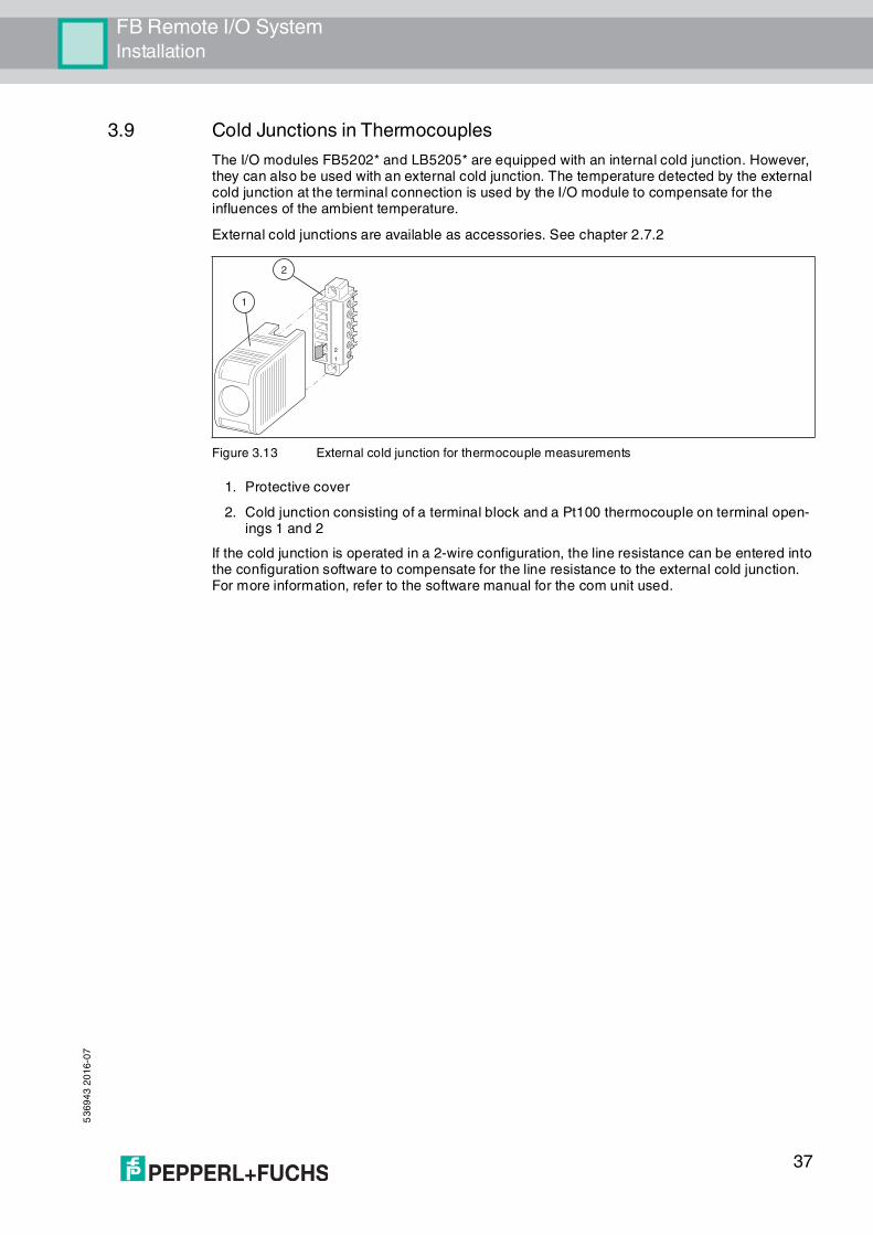
3.9 Cold Junctions in Thermocouples
The I/O modules FB5202* and LB5205* are equipped with an internal cold junction. However, they can also be used with an external cold junction. The temperature detected by the external cold junction at the terminal connection is used by the I/O module to compensate for the influences of the ambient temperature.
External cold junctions are available as accessories. See chapter 2.7.2
Figure 3.13 External cold junction for thermocouple measurements
1. Protective cover
2. Cold junction consisting of a terminal block and a Pt100 thermocouple on terminal open-ings 1 and 2
If the cold junction is operated in a 2-wire configuration, the line resistance can be entered into the configuration software to compensate for the line resistance to the external cold junction. For more information, refer to the software manual for the com unit used.
1
2
1
2

53
69
43
20
16
-07
38
FB Remote I/O SystemInstallation
3.10 Line Resistance in Resistance Thermometers
If you operate I/O modules FB5201* and FB5204* in a 2-wire configuration, the line resistance amounts to that of a resistor connected in series to the sensor and affects the measurement result. In order to avoid measurement errors, the line resistance must be measured and compensated for in this configuration. Two options are available here:
Short circuit the Pt100
1. Short circuit the Pt100 sensor.
2. In the configuration software, set the measuring input of the I/O module to resistance measurement.For more information, refer to the software manual for the com unit used.
3. Call up the measured value display for the I/O module and make a note of the measured value.
4. In the configuration software, set the measuring input of the I/O module to 2-wire measurement with Pt100 sensor.
5. Enter the measured resistance in the Line resistance field. The maximum permissible line resistance is 50 Ω.
Use a Calibrating Resistor
1. Use a calibrating terminal with an integrated calibrating resistor in the sensor supply line.
2. In the configuration software, set the measuring input of the I/O module to 2-wire measurement with Pt100 sensor.For more information, refer to the software manual for the com unit used.
3. In the configuration software, set the line resistance to 20 Ω.
4. Replace the Pt100 sensor at the measuring point with a 100-Ω measurement resistor.
5. To measure the resistance, call up the measured value display for the corresponding measuring point.
6. Set the displayed value to 0 °C using the calibration potentiometer.
7. Then reconnect the Pt100 sensor.

FB Remote I/O SystemInstallation
53
69
43
20
16
-07
39
3.11 Strain Gage Measurement
I/O modules FB4*01* and FB5202* can be interconnected for strain gage measurements. Use analog output FB4*01* to create a constant current, and the measuring input for temperature input FB5202* to process the millivolt signal for the resulting bridge voltage.
A constant current of 20 mA is sufficient to power a 350-Ω bridge. A bridge voltage of 7 V is produced. With a bridge sensitivity of 2 mV/V, a voltage of 14 mV results at full load.
Configuring I/O Modules for Strain Gage Measurement
1. Either set the FB4*01* analog output operating mode to simulation and select 20 mA as the simulation value, or set a fixed value of 20 mA via the fieldbus.
2. Set the FB5202* temperature input to a millivolt measurement mV.
3. Deactivate the cold junction of temperature input FB5202* by setting the thermostat temperature for the external cold junction to 0 °C.
Figure 3.14 Example of a strain gauge bridge
3.12 Redundancy
3.12.1 Basic Principles
Redundancy is used when it is necessary to guarantee operation of a remote I/O station despite one or more components having failed.
To set up a redundant system, use backplanes FB9262BP10220.0 and FB9262BP20220.0. These backplanes provide space for redundant com units, redundant bus termination modules, and redundant power supplies.
To ensure that the primary com unit and the redundant com unit use the same data record, both com units must be connected to one another. To do so, connect the com units via the front sockets using com unit connection cable LB9140A. It is possible to tell which com unit is active by looking at the operating mode LED. If the operating mode LED is flashing, the com unit is active. If the operating mode LED is not lit, the com unit is passive. For more information about the status LEDs, refer to the data sheet for the relevant com unit in use.
As a general rule, a distinction is made between media redundancy and application redundancy. Com units can be set to media redundancy or application redundancy using the configuration software. For more information, refer to the software manual for the com unit used.
Bus5*02
4*01
+
–
2+
5 -
6 -
5++–
Note!
Note that both com units in a redundant system must have the same firmware.
53
69
43
20
16
-07
40
FB Remote I/O SystemInstallation
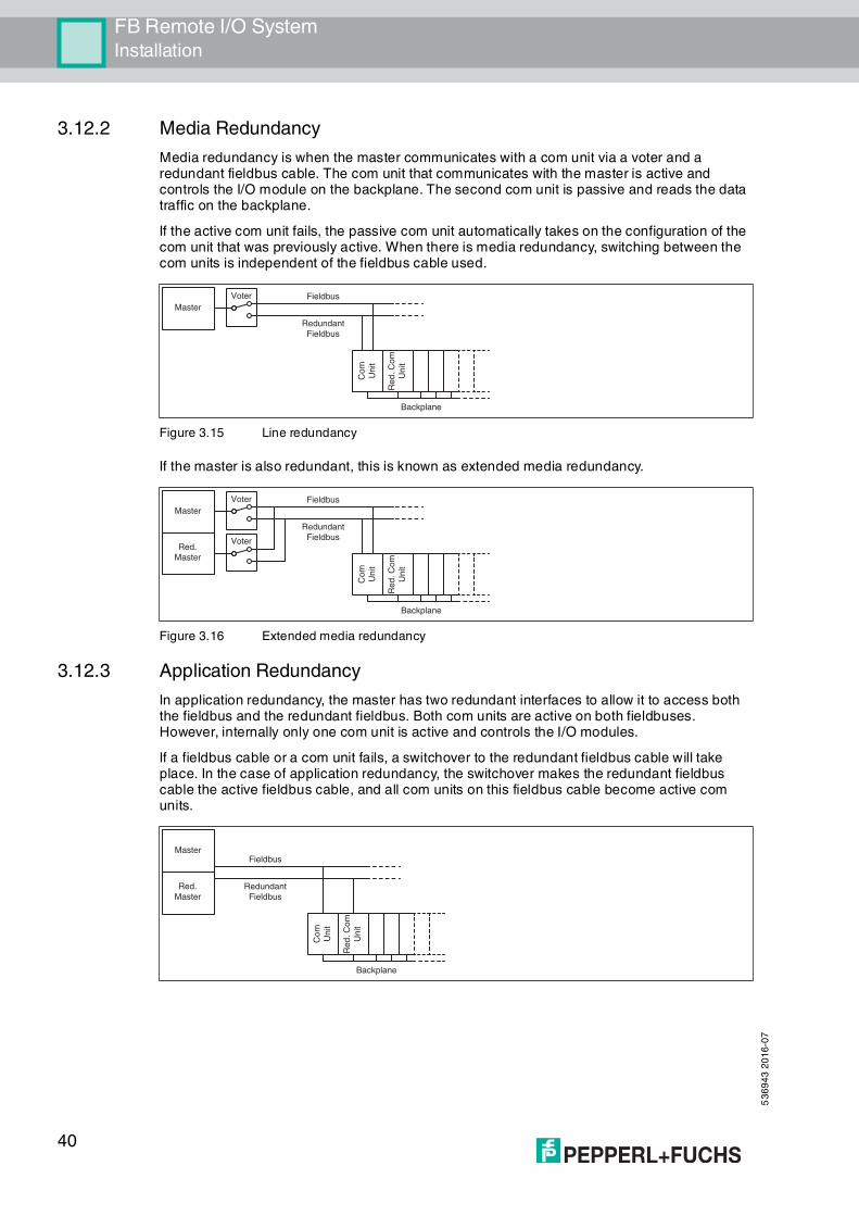
3.12.2 Media Redundancy
Media redundancy is when the master communicates with a com unit via a voter and a redundant fieldbus cable. The com unit that communicates with the master is active and controls the I/O module on the backplane. The second com unit is passive and reads the data traffic on the backplane.
If the active com unit fails, the passive com unit automatically takes on the configuration of the com unit that was previously active. When there is media redundancy, switching between the com units is independent of the fieldbus cable used.
Figure 3.15 Line redundancy
If the master is also redundant, this is known as extended media redundancy.
Figure 3.16 Extended media redundancy
3.12.3 Application Redundancy
In application redundancy, the master has two redundant interfaces to allow it to access both the fieldbus and the redundant fieldbus. Both com units are active on both fieldbuses. However, internally only one com unit is active and controls the I/O modules.
If a fieldbus cable or a com unit fails, a switchover to the redundant fieldbus cable will take place. In the case of application redundancy, the switchover makes the redundant fieldbus cable the active fieldbus cable, and all com units on this fieldbus cable become active com units.
Redundant
Fieldbus
Voter
Master
Fieldbus
Backplane
Co
m
Un
it
Re
d.
Co
m
Un
it
VoterRed.
Master
Redundant
Fieldbus
Voter
Master
Fieldbus
Backplane
Co
m
Un
it
Re
d.
Co
m
Un
it
Red.
Master
Redundant
Fieldbus
MasterFieldbus
Backplane
Co
m
Un
it
Re
d.
Co
m
Un
it

FB Remote I/O SystemInstallation
53
69
43
20
16
-07
41
3.13 Fieldbus Connection
Connection
The connections for the fieldbus and service bus are equipped with double terminals.
Connect the field bus to the appropriate terminals on the base backplane. See chapter 3.3.1
Cable length
Com units can be configured for various transfer rates. The required transfer rate and the bus system used dictate the maximum cable length.
For standard applications, the technical data for cable type A in accordance with DIN EN 61158 and DIN EN 61784 applies. The following table relates to standard applications.
Repeaters or fiber optic cables such as FOL7250* can be used to extend the cable length.
In accordance with DIN EN 61158 and DIN EN 61784, the following principles apply:
Linear bus structure without branches, consisting of a cable with terminators
Length of the spur to the node < 0.3 m
Total length of all spurs < 6 m
Data transfer via shielded twisted pair cable
Danger!
Risk of Explosion
Improperly installed fieldbuses can cause explosive mixtures to ignite.
Observe the wiring specifications set out in IEC/EN 60079-14 for laying lines in a hazardous area.
Danger!
Risk of Explosion
Accessories that do not meet the requirements for use in hazardous areas can cause explosive mixtures to ignite.
Only use accessories and devices that are approved for use in the respective environment.
Bus system Transfer rate Max. cable length
MODBUS 1.2 kbit/s ... 9.6 kbit/s 1200 m
19.2 kbit/s 1200 m
38.4 kbit/s 1200 m
115.2 kbit/s 1000 m
PROFIBUS DP 9.6 kbit/s 1200 m
19.2 kbit/s 1200 m
93.75 kbit/s 1200 m
187.5 kbit/s 1000 m
500 kbit/s 400 m
1.5 Mbit/s 200 m
PROFIBUS PA 31.25 kbit/s 1900 m
FOUNDATION fieldbus H1 31.25 kbit/s 1900 m
Service bus 9600 bit/s 1200 m

53
69
43
20
16
-07
42
FB Remote I/O SystemInstallation
Terminator resistance 100 Ω ... 130 Ω
Core cross-section > 0.22 mm², approx. 60 pF/m
Max. cable length 1200 m, depending on the transfer rate
Max. 32 active or passive nodes including repeaters
Max. 3 repeaters between 2 nodes
Terminators
The fieldbus must have exactly two terminators per segment, one at the start and one at the end. A segment usually starts at the master, while the last remote I/O unit is taken to be the end of the segment. A segment also ends or begins at a repeater or a fiber optic cable.
To install a terminator, use the following bus termination modules.
Terminator for a service bus: FB9293*
Terminator for a fieldbus: FB9294*
Terminator for a service bus and a fieldbus: FB9295*
Figure 3.17 Block diagram for FB9293*, FB9294*, FB9295*
Zone 1
FB9293 FB9294 FB9295
Example!
A bus with 3 segments, 1 master, a fiber optic cable transfer path, 4 nodes, and 1 repeater has
6 terminators (T).
Master(T) — Node — (T)Fiber optic cable(T) — Node — (T)Repeater(T) — Node — (T)Node

FB Remote I/O SystemInstallation
53
69
43
20
16
-07
43
3.14 Potential Equalization and Shielding
3.14.1 Interference
Electromagnetic fields can interfere with the communication path.
Figure 3.18 Interfering signals caused by induction in parallel conductors
Twisted-pair cables significantly reduce the influence of these interference fields, particularly when compared to cables with parallel strands. The direction of the recorded interference field in a twisted-pair cable reverses over short intervals. This means that the induced interference is practically canceled out, while in parallel strands the interference is active across the entire area.
Figure 3.19 Reduced admission of interfering signals in twisted-pair cable
A shielding keeps interfering signals away from the communication path.
Figure 3.20 Shielding prevents the entry of interference fields
EMC filters are used in many devices to divert any interference to ground. For the sake of symmetry, all lines are provided with suitable capacitance. Capacitively coupled high-frequency interference is effectively canceled out by the symmetrical layout.
Figure 3.21 EMC filters in signal paths
Note!
The following subchapters cannot provide the reader with a complete picture of all
requirements in terms of grounding, shielding, and lightning protection. More information on
this topic can be found in the technical literature and the applicable standards.

53
69
43
20
16
-07
44
FB Remote I/O SystemInstallation
The same applies to galvanically isolated signals. However, unexpected results may arise in networks created by multichannel systems without isolation. This is because the filter capacitors may even run in parallel, depending on the setup. Isolate the channels to eliminate any interference.
Figure 3.22 EMC filters in a network (simplified diagram)
3.14.2 Wiring
Lay the signal leads such that they are separate from the power cables. Please note that AC voltages and current spikes can induce stray voltages in neighboring lines. Thus, shielded cables should be used for EMC-tested devices.
Grounding bars can be laid separately from the shielding (see IEC/EN 60079-14). The shielding is then grounded at one point.
Field Wiring
Depending on the application, the shielding of the wiring must be grounded at one point or at both ends. If possible, avoid grounding at both ends to prevent ground loops and ensure the shielding is not used as a return line.
Sound results can be obtained with grounding at one end of the cable if the cable is laid on a grounded metal cable support. The metal frame in the immediate vicinity of the conductor ensures that only small areas are exposed to the field, so that interference is largely reduced.
Digital inputs are normally controlled by NAMUR proximity switches with a low-impedance signal. In this case, interfering signals have a far lower impact than in circuits containing open switches that do not have an additional resistor circuit. For this reason, do not connect digital inputs to exposed wiring.
The analog signals of resistive sensors or thermocouples are particularly susceptible to interference. Signal converters have built-in filters to reduce this interference. The filters can be switched on if fluctuations in the measuring signal cannot be reduced sufficiently by other means. For more information, refer to the software manual for the com unit used.
Danger!
Risk of Explosion
Observe the specifications for installation as set out in IEC/EN 60079-14.

FB Remote I/O SystemInstallation
53
69
43
20
16
-07
45
Fieldbus Connection
Ground the shielding of the fieldbus cable at both ends. Grounding at one end is sufficient if the fieldbus cable is laid on a grounded metal cable support.
Eliminating Interference
The following measures can improve power.
1. Fit line filters in power supply lines.Please make sure that supply cables leading to line filters are laid separately from other ca-bles to ensure that any filtered interference is not picked up again.
2. Fit surge protection filters in signal lines.
3. Change to galvanically isolated circuits.
3.15 System Expansion
Adding I/O Modules
By adding an I/O-module, input or output data will be transferred to a slot that was previously empty. To do this, the configuration of the com unit must be adapted. Changes to the configuration of the com unit usually result in the function being interrupted due to a fieldbus restart.
To avoid this, you can activate Hot Configuration in Run (HCiR) in the com unit. If HCiR is active, a new configuration can be transferred to the com unit in the form of a passive data record. In this way, the master still has access to the old configuration in its existing form. As soon as the new configuration in the master matches the new configuration in the com unit, the new configuration in the com unit is activated and the old configuration is deleted. For more information, refer to the software manual for the com unit used.
Alternatively, you can use Unicom com unit FB8209*. Using the Unicom com unit, you can configure the slots on the backplane in such a way that they can later be used with different I/O modules. For more information, refer to the software manual for Unicom com unit FB8209*.
Extending the Fieldbus
In order to extend the fieldbus cable, the bus termination module may have to be removed. In this case, operation can only be maintained using a redundant system.

53
69
43
20
16
-07
46
FB Remote I/O SystemCommissioning
4 Commissioning
4.1 Electrical Testing of Connections
Make sure that the terminators have been properly fitted to the fieldbus and service bus. See chapter 3.13
Test of Physical Connection Right to the End of the Segment
1. Disconnect the bus connector from the master.
2. Deactivate the terminator on the bus connector (bus start).
3. Measure the voltage at the bus connector between A and B.
A voltage of U = 220 Ω / (220 Ω + 2 * 390 Ω) * 5 V = 1.1 V must be present between A and B. This voltage comes from the field-side terminator.If the 1.1 V voltage is not present, there is either no terminator connected at the end, the cable is faulty, or there is no terminating voltage at the remote I/O station.
4. Measure the current at the bus connector between A and B.
It must be possible to measure a current of I = 5 V / (2 * 390 Ω) ≈ 6.4 mA between A and B. If the current is significantly higher, by a factor of 2 or more, the bus is terminated using more than one terminator. If the current is I ≈ 0 mA, then either there is no terminator present, the cable is faulty, or there is no terminating voltage. In this case, a resistance of 220 Ω should be measured between A and B.If no current or resistance can be measured, the terminator at the end of the bus is missing or the cable is faulty.
5. Activate the terminator on the bus connector for the master.
6. Plug the bus connector back into the master.
Test of Physical Remote I/O Station Connection
1. Disconnect the bus connector from the master.
2. Deactivate the terminator on the bus connector (bus start).
3. Measure the voltage between A and B on the bus connection of each remote I/O station.
A voltage of U = 1.1 V must be present between A and B on each remote I/O station.
4. Activate the terminator on the bus connector for the master.
5. Plug the bus connector back into the master.
Tip
Perform the measurements from the control room.
Danger!
Risk of explosion
When taking measurements in hazardous areas, there is a risk of explosion from sparks forming.
Take measurements on the terminal connections of a remote I/O station, with a hot work permit only, in other words when there is no potentially explosive atmosphere.

FB Remote I/O SystemCommissioning
53
69
43
20
16
-07
47
4.2 Configuration
The entire remote I/O station is configured via the com unit. Communication with the com unit can be set up via either the fieldbus or the service bus.
For more information, refer to the software manual for the com unit used.
4.3 Startup Phase
Do not start to operate all the remote I/O stations simultaneously; instead, connect each remote I/O station to the master in succession.
Ensure that the master read cycle and the com unit watchdog are coordinated with one another. The duration for the transition to substitute values must be longer than the duration of a bus cycle.
For the purposes of fault analysis, we recommend using a bus monitor that is capable of passively monitoring data telegrams on the fieldbus.
Temporary Overload of the Power Supply
To avoid an overload of the power supply in the startup phase as a result of increased startup currents, the number of certain I/O modules on the backplane is limited.
Use:
a maximum of 11 single-channel I/O modules of type FB3*, FB4*.Each of these I/O modules consumes 9.09 % of the startup capacity.
or a maximum of eight four-channel I/O modules of type FB3*.Each of these I/O modules consumes 12.5 % of the startup capacity.
Note!
Please refer to the current literature for more information.
Note!
Com unit FB8207* can be configured via the service bus only.

53
69
43
20
16
-07
48
FB Remote I/O SystemOperation
5 Operation
During operation, you can access up-to-date measured values and diagnostic information for the I/O modules via the com unit. For more information, refer to the software manual for the com unit used.
In addition, you can read off basic information about supply and communication from the LEDs on the I/O modules and com units. For more information about the LEDs, refer to the data sheets for the I/O modules and com units used.

FB Remote I/O SystemTroubleshooting
53
69
43
20
16
-07
49
6 Troubleshooting
Communication errors
Danger!
Risk of explosion
When work is performed on the remote I/O unit in hazardous areas, there is a risk of explosion from spark formation.
Before starting any work on the remote I/O unit, familiarize yourself with the instruction manuals for the components and their relevant certificates.
Fault Remedy
Communication error on the fieldbus
Check that the cables are connected.
Check that the transmitting and receiving lines are wired correctly
and have not been swapped.
Check that the nodes are positioned in linear form and without
branches. A star-shaped layout is not permitted.
Check that the terminator has been activated. The fieldbus must
have exactly two terminators per segment, one at the beginning
and one at the end.
In the configuration software, check that the selected address is
the same as the remote I/O station address.
In the configuration software, check whether the master read cycle
and the com unit watchdog are coordinated with one another.
Communication error on the service bus
Check that the cables are connected.
Check that the nodes are positioned in linear form and without
branches. A star-shaped layout is not permitted.
Check that the terminator has been activated. The service bus
must have exactly two terminators per segment, one at the
beginning and one at the end.
In the configuration software, check that the selected address is
the same as the remote I/O station address.
Check that the correct interface is preset in the configuration
software.
Communication error on the service bus after successfully establishing a connection
Check that the service bus is galvanically isolated.
If you are using a laptop, operate the laptop using a battery.
Check the settings for the baud rate and transfer direction.
A new remote I/O station will not work on a bus if other remote I/O stations are already operating on the bus
Check that the terminators are still on the beginning and end of the bus after expansion.
The software cannot locate a com unit when establishing the connection
Check that the com unit is plugged in correctly.

53
69
43
20
16
-07
50
FB Remote I/O SystemTroubleshooting
Redundancy Faults
Signal Faults
Communication to the extension backplane is not possible
If backplanes FB9262BP10220.0 and FB9262BP20220.0 are
used, check if the plug-in jumpers are set correctly.
Check that the base backplane and the extension backplane are
wired correctly.
Bus-independent deactivation of the I/O modules is not possible
If backplanes FB9262BP10220.0 and FB9262BP20220.0 are used, check if the plug-in jumpers are set correctly.
Multiple I/O modules fail simultaneously
Check that the power supply is working properly.
Check that the base backplane and the extension backplane are
wired correctly.
Fault Remedy
Continuous redundancy switchover
Check that the correct type of redundancy is selected (media
redundancy or application redundancy).
In the configuration software, check whether the master read cycle
and the com unit watchdog are coordinated with one another.
Check whether the com units are connected via the front sockets
using com unit connection cable LB9140A.
Check that the process control system is set to the correct type of
redundancy.
No redundancy switchover when a com unit is removed
Check that redundancy has been configured at the com unit.
Check whether the com units are connected via the front sockets
using com unit connection cable LB9140A.
I/O modules are continuously changing the data
Check whether one of the com units has not been configured for redundancy mode. If this is the case, both com units actively try to access the I/O modules and interfere with one another.
Fault Remedy
Faulty signal Check whether the I/O module is in simulation mode or whether it
is working with substitute values.
Check if there is a short circuit or lead breakage within the circuit.
Check that the field devices and sensors are working properly.
Check the communication path to the I/O module.
If necessary, replace the I/O module.
All signals for a station are faulty
Check that the power supply is working properly.
Check the bus connection.
Check the bus communication using a bus monitor.
The output module switches off
Communication with the com unit is interrupted.
Check that the I/O module is plugged into the backplane properly.
If necessary, switch off the status bits for analog outputs in the
configuration software.
Fault Remedy

FB Remote I/O SystemTroubleshooting
53
69
43
20
16
-07
51
Input module sporadically delivers no measured values
Communication with the com unit is interrupted. Check that the I/O module is plugged into the backplane properly.
Measured values occasionally incorrect
Check whether the measured value is being distorted by external
influences.
Check that the shielding is intact.
I/O module reported to be faulty
Check that the correct I/O module is plugged in.
Check that the green LED on the I/O module is lit and that the I/O
module is correctly plugged in.
Fault Remedy

Subject to modifications Copyright PEPPERL+FUCHS • Printed in Germany
www.pepperl-fuchs.com
Worldwide HeadquartersPepperl+Fuchs GmbH68307 Mannheim · GermanyTel. +49 621 776-0E-mail: [email protected]
For the Pepperl+Fuchs representative closest to you check www.pepperl-fuchs.com/contact
PROCESS AUTOMATION –PROTECTING YOUR PROCESS
536943 / TDOCT-1166LENG
07/2016