compact dimensions and light weight - rotzler · 1. definitions titan th 1 th 2 th 3 th 5 tc 1 tc 2...
TRANSCRIPT
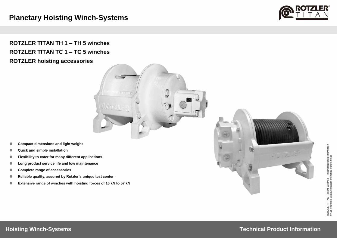
Planetary Hoisting Winch-Systems
Hoisting Winch-Systems Technical Product Information
RO
TZ
LE
R T
ITA
N H
ois
tin
g w
inch
es –
Te
chn
ica
l p
rod
uct in
form
atio
n
07
.15
Te
ch
nic
al d
ata
are
su
bje
ct
to c
ha
ng
e w
ith
ou
t n
otice.
ROTZLER TITAN TH 1 – TH 5 winches
ROTZLER TITAN TC 1 – TC 5 winches
ROTZLER hoisting accessories
Compact dimensions and light weight
Quick and simple installation
Flexibility to cater for many different applications
Long product service life and low maintenance
Complete range of accessories
Reliable quality, assured by Rotzler’s unique test center
Extensive range of winches with hoisting forces of 10 kN to 57 kN

Content
Hoisting Winch-Systems Technical Product Information
TITAN TH 1 TH 2 TH 3 TH 5 TC 1 TC 2 TC 3 TC 5 winches
2
RO
TZ
LE
R T
ITA
N H
ois
tin
g w
inch
es –
Te
chn
ica
l p
rod
uct in
form
atio
n
07
.15
Te
ch
nic
al d
ata
are
su
bje
ct
to c
ha
ng
e w
ith
ou
t n
otice.
1. Definitions
3
2. General Descriptions
4
3. Specification
Connections 5
Ambient conditions 6
Fluids 6
4. Performance Data, Dimensions, Order Codes
TITAN TH 1 winches 7 - 9
TITAN TH 2 winches 10 - 12
TITAN TH 3 winches 13 - 15
TITAN TH 5 winches 16 - 18
TITAN TC 1 winches 19 - 21
TITAN TC 2 winches 22 - 24
TITAN TC 3 winches 25 - 27
TITAN TC 5 winches 28 - 30
5. Installation Instructions
Mechanic installation 31
Hydraulic installation 32 - 34
6. Options and Accessories
MCD 35 - 37
Stainless steel fasteners 38
External break release 38
Counterbalance valve 39
Pressure roller 39
Grooved drum sleeves 39
Hook weight system 40 - 43
Top roller 44
Swivel hook 45
Ropes 45
7. Service
46

1. Definitions
TITAN TH 1 TH 2 TH 3 TH 5 TC 1 TC 2 TC 3 TC 5 winches
3
Hoisting Winch-Systems Technical Product Information
RO
TZ
LE
R T
ITA
N H
ois
tin
g w
inch
es –
Te
chn
ica
l p
rod
uct in
form
atio
n
07
.15
Te
ch
nic
al d
ata
are
su
bje
ct
to c
ha
ng
e w
ith
ou
t n
otice.
Abbreviation Description
A ampere
bar unit of pressure (1 bar = 14,5 psi)
CC counter clockwise
CW clockwise
cc cubic centimeter
ft/min feet per minute
F (hoisting) force
Fmax maximum (hoisting) force
g/ml specific weight
h Hour
I max. [A] maximum amperage
I nenn. [A] rated amperage
kg kilograms
kN kilonewton
lbs pounds
l/min liter per minute
M3 mechanism class = ISO 4301-1 (resp. 1 Bm according to FEM 9.511)
mA milliampere
m/min meter per minute
MCD Measuring Control Device
mm millimeter
mmÇ/s viscosity
[Nm] newtonmeter
p l leakage pressure
p l max. [bar / psi] maximum leakage pressure
psi pounds per square inch
p x back pressure
p x max. [bar / psi] maximum back pressure
p y return flow pressure
p y max. [bar / psi] maximum return flow pressure
°C centigrade (Celsius)
T [°C] temperature
U max. [V] maximum voltage
U nenn. [V] voltage
USGPM US gallons per minute
Abbreviation Description
V Volt
vis [cSt] viscosity (centi Stoke)
vis min minimum viscosity
vis opt optimal operating viscosity
vis max maximum viscosity
μm micrometer
” inch
% per cent

2. General Descriptions
TITAN TH 1 TH 2 TH 3 TH 5 TC 1 TC 2 TC 3 TC 5 winches
4
Hoisting Winch-Systems Technical Product Information
RO
TZ
LE
R T
ITA
N H
ois
tin
g w
inch
es –
Te
chn
ica
l p
rod
uct in
form
atio
n
07
.15
Te
ch
nic
al d
ata
are
su
bje
ct
to c
ha
ng
e w
ith
ou
t n
otice.
Designated use
The Rotzler TITAN winches belong to the group of hoisting winches. The use as determined is hoisting and lowering of loads as specified for each winch type and under the attention of the given installation regulations as well as of the safety notes. Any other use is prohibited. Passenger transport with a. m. winches is prohibited. The use as determined also includes the related equipment manufacturer’s recommendations regarding installation, operation and maintenance. No structural modifications or changes may be done on the unit. Only original spare parts of ROTZLER may be used. The operator has the duty to observe the instructions given in the operating manual and maintenance manual. Theoretical using time
Drive group M3
class of operating time: T3
theoretical using time (years): 12,8 - 6,4
at an average, daily operat. time (h): 0,5 - 1,0
calc. total operating time (h): 1600
load spectrum: L2
hours of full line pull (h): 400
3. Specifications
TITAN TH 1 TH 2 TH 3 TH 5 TC 1 TC 2 TC 3 TC 5 winches
5
Hoisting Winch-Systems Technical Product Information
RO
TZ
LE
R T
ITA
N H
ois
tin
g w
inch
es –
Te
chn
ica
l p
rod
uct in
form
atio
n
07
.15
Te
ch
nic
al d
ata
are
su
bje
ct
to c
ha
ng
e w
ith
ou
t n
otice.
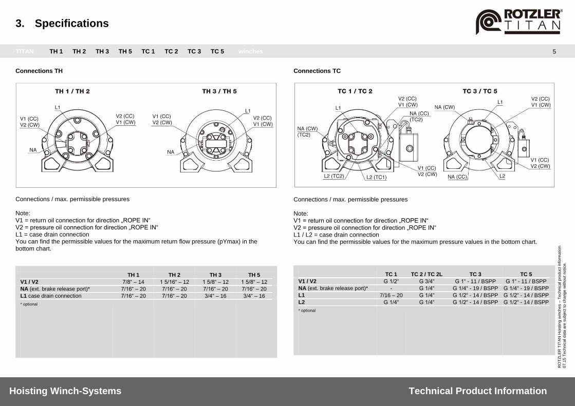
Connections TH
Connections / max. permissible pressures Note: V1 = return oil connection for direction „ROPE IN“ V2 = pressure oil connection for direction „ROPE IN“ L1 = case drain connection You can find the permissible values for the maximum return flow pressure (pYmax) in the bottom chart. TH 1 TH 2 TH 3 TH 5
V1 / V2 7/8“ – 14 1 5/16“ – 12 1 5/8“ – 12 1 5/8“ – 12
NA (ext. brake release port)* 7/16“ – 20 7/16“ – 20 7/16“ – 20 7/16“ – 20
L1 case drain connection 7/16“ – 20 7/16“ – 20 3/4“ – 16 3/4“ – 16
* optional
Connections TC
Connections / max. permissible pressures Note: V1 = return oil connection for direction „ROPE IN“ V2 = pressure oil connection for direction „ROPE IN“ L1 / L2 = case drain connection You can find the permissible values for the maximum pressure values in the bottom chart.
TC 1 TC 2 / TC 2L TC 3 TC 5
V1 / V2 G 1/2“ G 3/4“ G 1“ - 11 / BSPP G 1“ - 11 / BSPP
NA (ext. brake release port)* - G 1/4“ G 1/4“ - 19 / BSPP G 1/4“ - 19 / BSPP
L1 7/16 – 20 G 1/4“ G 1/2“ - 14 / BSPP G 1/2“ - 14 / BSPP
L2 G 1/4“ G 1/4“ G 1/2“ - 14 / BSPP G 1/2“ - 14 / BSPP
* optional

3. Specifications
TITAN TH 1 TH 2 TH 3 TH 5 TC 1 TC 2 TC 3 TC 5 winches
6
Hoisting Winch-Systems Technical Product Information
RO
TZ
LE
R T
ITA
N H
ois
tin
g w
inch
es –
Te
chn
ica
l p
rod
uct in
form
atio
n
07
.15
Te
ch
nic
al d
ata
are
su
bje
ct
to c
ha
ng
e w
ith
ou
t n
otice.
Ambient conditions Temperature range
The ROTZLER TITAN winches are designed for operation in a temperature range/ambient temperature of -30 °C up to +60 °C. Please contact Rotzler regarding extreme temperatures, vibrations, jerks, sand, dust, sea water or any other extreme environmental conditions.
Fluids Gear oil specification
Specification SAE 80W-90
Before delivery the ROTZLER TITAN hoisting winches were filled with a usual gear oil (SAE80W-90-API-GL5)
mil. spec. API- GL 5
specific weight at 15° C 0,90 g/ml
viscosity at 40° C 92 mmÇ/s
viscosity at 100° C 11 mmÇ/s
pour-point -27°C
flash point +240°C
Hydraulic oil (not supplied by ROTZLER)
The integrated hydraulic components are designed for the use with hydraulic oil on mineral oil basis according to DIN 51525. Operating viscosity range
The viscosity of the hydraulic fluid should be chosen in correspondence with a consideration to the ambient temperature and the viscosity requirements of the pumps and motors. The optimal operating viscosity recommended by us is visopt. = 50 mm2/s (cSt). Viscosity limits
The following viscosity limits apply: vismin. > 10 mm2/s (cSt) short term at a max. permissible leakage oil temperature of Tmax. = +90° C. vismax. < 1000 mm2/s (cSt) short term on cold start. Recommended hydraulic oil / fields of application
H-LP 22: for Northern conditions. H-LP 32 or 46: for conditions in Central and Southern Europe. H-LP 68 or 100: for tropical conditions. Hydraulic oil temperature
At normal operation of the winch system hydraulic oil temperatures should be between + 30° C and + 60° C. If the oil temperature is too low respectively too high, the sealing rings will loose their sealing characteristics. Further the durability of the hydraulic oil will be reduced, in case the oil temperature of + 60° C is exceeded. vismax < 1000 mm2/s (cSt) short term on cold start.
4. Performance Data, Dimensions, Order Codes
TITAN TH 1 TH 2 TH 3 TH 5 TC 1 TC 2 TC 3 TC 5 winches
7
Hoisting Winch-Systems Technical Product Information
RO
TZ
LE
R T
ITA
N H
ois
tin
g w
inch
es –
Te
chn
ica
l p
rod
uct in
form
atio
n
07
.15
Te
ch
nic
al d
ata
are
su
bje
ct
to c
ha
ng
e w
ith
ou
t n
otice.
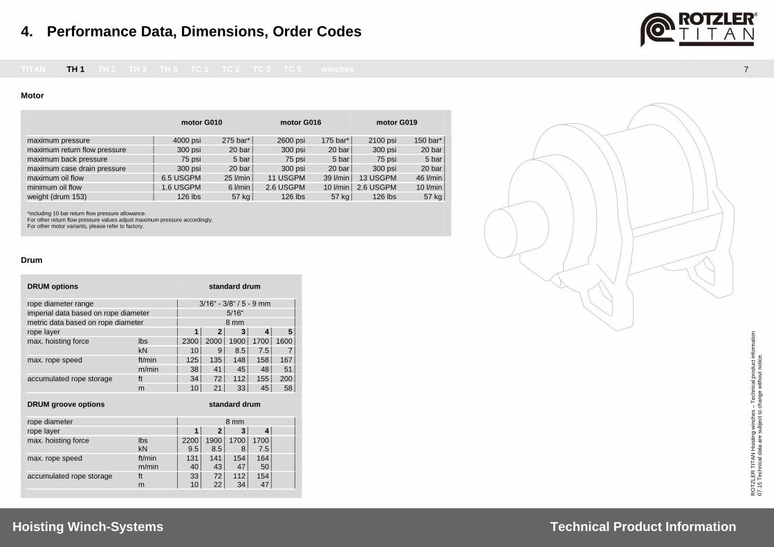
Motor motor G010 motor G016 motor G019
maximum pressure 4000 psi 275 bar* 2600 psi 175 bar* 2100 psi 150 bar*
maximum return flow pressure 300 psi 20 bar 300 psi 20 bar 300 psi 20 bar
maximum back pressure 75 psi 5 bar 75 psi 5 bar 75 psi 5 bar
maximum case drain pressure 300 psi 20 bar 300 psi 20 bar 300 psi 20 bar
maximum oil flow 6.5 USGPM 25 l/min 11 USGPM 39 l/min 13 USGPM 46 l/min
minimum oil flow 1.6 USGPM 6 l/min 2.6 USGPM 10 l/min 2.6 USGPM 10 l/min
weight (drum 153) 126 lbs 57 kg 126 lbs 57 kg 126 lbs 57 kg
*including 10 bar return flow pressure allowance.
For other return flow pressure values adjust maximum pressure accordingly. For other motor variants, please refer to factory.
Drum
DRUM options standard drum
rope diameter range 3/16“ - 3/8“ / 5 - 9 mm
imperial data based on rope diameter 5/16“
metric data based on rope diameter 8 mm
rope layer 1 2 3 4 5
max. hoisting force lbs 2300 2000 1900 1700 1600
kN 10 9 8.5 7.5 7
max. rope speed ft/min 125 135 148 158 167
m/min 38 41 45 48 51
accumulated rope storage ft 34 72 112 155 200
m 10 21 33 45 58
DRUM groove options standard drum
rope diameter 8 mm
rope layer 1 2 3 4
max. hoisting force lbs kN
2200 9.5
1900 8.5
1700 8
1700 7.5
max. rope speed ft/min m/min
131 40
141 43
154 47
164 50
accumulated rope storage ft m
33 10
72 22
112 34
154 47

4. Performance Data, Dimensions, Order Codes
TITAN TH 1 TH 2 TH 3 TH 5 TC 1 TC 2 TC 3 TC 5 winches
8
Hoisting Winch-Systems Technical Product Information
RO
TZ
LE
R T
ITA
N H
ois
tin
g w
inch
es –
Te
chn
ica
l p
rod
uct in
form
atio
n
07
.15
Te
ch
nic
al d
ata
are
su
bje
ct
to c
ha
ng
e w
ith
ou
t n
otice.
Dimensions basic
... with options and accessories
motor G010 / standard drum A A
1 B C D E F G H I I
1 J K L
dimensions imperial (max.) – inches 12.6 13.46 15.5 11.0 8.5 9.0 7.2 0.5 6.0 7.0 7.4 10.6 5.6 0.6
dimensions metric (max.) – mm 320 342 400 280 215 230 184 12.7 153 178 187.8 270 141 15.5
motor G016 / standard drum A A
1 B C D E F G H I I
1 J K L
dimensions imperial (max.) – inches 12.4 13.46 16.1 11.0 8.5 9.0 7.2 0.5 6.0 7.0 7.4 10.6 5.6 0.6
dimensions metric (max.) – mm 320 342 410 280 215 230 184 12.7 153 178 187.8 270 141 15.5
motor G019 / standard drum A A
1 B C D E F G H I I
1 J K L
dimensions imperial (max.) – inches 12.6 13.46 16.3 11.0 8.5 9.0 7.2 0.5 6.0 7.0 7.4 10.6 5.6 0.6
dimensions metric (max.) – mm 320 342 415 280 215 230 184 12.7 153 178 187.8 270 141 15.5
A1 = with MCD 1 / pressure roller
I1 = with grooves
4. Performance Data, Dimensions, Order Codes
TITAN TH 1 TH 2 TH 3 TH 5 TC 1 TC 2 TC 3 TC 5 winches
9
Hoisting Winch-Systems Technical Product Information
RO
TZ
LE
R T
ITA
N H
ois
tin
g w
inch
es –
Te
chn
ica
l p
rod
uct in
form
atio
n
07
.15
Te
ch
nic
al d
ata
are
su
bje
ct
to c
ha
ng
e w
ith
ou
t n
otice.
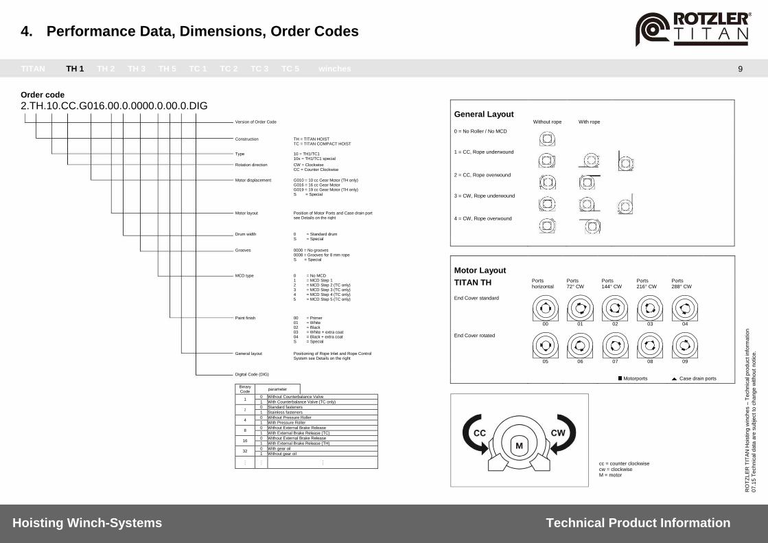
Order code
2.TH.10.CC.G016.00.0.0000.0.00.0.DIG
General Layout Without rope With rope 0 = No Roller / No MCD
1 = CC, Rope underwound
2 = CC, Rope overwound
3 = CW, Rope underwound
4 = CW, Rope overwound
Motor Layout
TITAN TH Ports horizontal
Ports 72° CW
Ports 144° CW
Ports 216° CW
Ports 288° CW
End Cover standard
00
01
02
03
04
End Cover rotated
05
06
07
08
09
Motorports Case drain ports
cc = counter clockwise cw = clockwise M = motor
Version of Order Code
Construction TH = TITAN HOIST TC = TITAN COMPACT HOIST
Type 10 = TH1/TC1 10s = TH1/TC1 special
Rotation direction CW = Clockwise CC = Counter Clockwise
Motor displacement G010 = 10 cc Gear Motor (TH only) G016 = 16 cc Gear Motor G019 = 19 cc Gear Motor (TH only) S = Special
Motor layout Position of Motor Ports and Case drain port see Details on the right
Drum width 0 = Standard drum S = Special
Grooves 0000 = No grooves 0008 = Grooves for 8 mm rope S = Special
MCD type 0 = No MCD 1 = MCD Step 1 2 = MCD Step 2 (TC only) 3 = MCD Step 3 (TC only) 4 = MCD Step 4 (TC only) 5 = MCD Step 5 (TC only)
Paint finish 00 = Primer 01 = White 02 = Black 03 = White + extra coat 04 = Black + extra coat S = Special
General layout Positioning of Rope Inlet and Rope Control System see Details on the right
Digital Code (DIG)
Binary Code
parameter
1 0 Without Counterbalance Valve
1 With Counterbalance Valve (TC only)
2 0 Standard fasteners
1 Stainless fasteners
4 0 Without Pressure Roller
1 With Pressure Roller
8 0 Without External Brake Release
1 With External Brake Release (TC)
16 0 Without External Brake Release
1 With External Brake Release (TH)
32 0 With gear oil
1 Without gear oil
.
. . . . .
.
. .

4. Performance Data, Dimensions, Order Codes
TITAN TH 1 TH 2 TH 3 TH 5 TC 1 TC 2 TC 3 TC 5 winches
10
Hoisting Winch-Systems Technical Product Information
RO
TZ
LE
R T
ITA
N H
ois
tin
g w
inch
es –
Te
chn
ica
l p
rod
uct in
form
atio
n
07
.15
Te
ch
nic
al d
ata
are
su
bje
ct
to c
ha
ng
e w
ith
ou
t n
otice.
Motor motor G019 motor G031
maximum pressure 4000 psi 275 bar** 2600 psi 170 bar*
maximum return flow pressure 300 psi 20 bar 300 psi 20 bar
maximum back pressure 75 psi 5 bar 75 psi 5 bar
maximum case drain pressure 300 psi 20 bar 300 psi 20 bar
maximum oil flow 14 USGPM 51 l/min 22 USGPM 83 l/min
minimum oil flow 4 USGPM 12 l/min 6 USGPM 20 l/min
weight (drum 180) 170 lbs 77 kg 170 lbs 77 kg
*including 10 bar return flow pressure allowance.
For other return flow pressure values adjust maximum pressure accordingly. For other motor variants, please refer to factory.
Drum
DRUM options standard drum
rope diameter range 1/4“ - 1/2“ / 6 - 12 mm
imperial data based on rope diameter 3/8“
metric data based on rope diameter 10 mm
rope layer 1 2 3 4 5
max. hoisting force lbs 4500 4100 3700 3500 3200
kN 20 18 16.5 15 14
max. rope speed ft/min 132 144 157 169 182
m/min 40 44 48 52 56
accumulated rope storage ft 37 77 120 166 215
m 10 21 34 47 61
DRUM groove options standard drum rope diameter 10 mm
rope layer 1 2 3 4
max. hoisting force lbs kN
4300 19
3900 17
3600 16
3300 14.5
max. rope speed ft/min m/min
138 42
151 46
164 50
177 54
accumulated rope storage ft m
33 10
72 22
114 35
160 49
4. Performance Data, Dimensions, Order Codes
TITAN TH 1 TH 2 TH 3 TH 5 TC 1 TC 2 TC 3 TC 5 winches
11
Hoisting Winch-Systems Technical Product Information
RO
TZ
LE
R T
ITA
N H
ois
tin
g w
inch
es –
Te
chn
ica
l p
rod
uct in
form
atio
n
07
.15
Te
ch
nic
al d
ata
are
su
bje
ct
to c
ha
ng
e w
ith
ou
t n
otice.
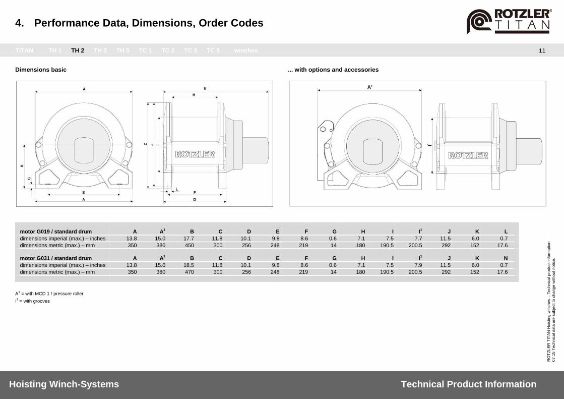
Dimensions basic
... with options and accessories
motor G019 / standard drum A A
1 B C D E F G H I I
1 J K L
dimensions imperial (max.) – inches 13.8 15.0 17.7 11.8 10.1 9.8 8.6 0.6 7.1 7.5 7.7 11.5 6.0 0.7
dimensions metric (max.) – mm 350 380 450 300 256 248 219 14 180 190.5 200.5 292 152 17.6
motor G031 / standard drum A A
1 B C D E F G H I I
1 J K N
dimensions imperial (max.) – inches 13.8 15.0 18.5 11.8 10.1 9.8 8.6 0.6 7.1 7.5 7.9 11.5 6.0 0.7
dimensions metric (max.) – mm 350 380 470 300 256 248 219 14 180 190.5 200.5 292 152 17.6
A1 = with MCD 1 / pressure roller
I1 = with grooves

4. Performance Data, Dimensions, Order Codes
TITAN TH 1 TH 2 TH 3 TH 5 TC 1 TC 2 TC 3 TC 5 winches
12
Hoisting Winch-Systems Technical Product Information
RO
TZ
LE
R T
ITA
N H
ois
tin
g w
inch
es –
Te
chn
ica
l p
rod
uct in
form
atio
n
07
.15
Te
ch
nic
al d
ata
are
su
bje
ct
to c
ha
ng
e w
ith
ou
t n
otice.
Order code
2.TH.20.CC.G019.00.0.0000.0.00.0.DIG
General Layout Without rope With rope 0 = No Roller / No MCD
1 = CC, Rope underwound
2 = CC, Rope overwound
3 = CW, Rope underwound
4 = CW, Rope overwound
Motor Layout
TITAN TH Ports horizontal
Ports 72° CW
Ports 144° CW
Ports 216° CW
Ports 288° CW
End Cover standard
00
01
02
03
04
End Cover rotated
05
06
07
08
09
Motorports Case drain ports
cc = counter clockwise cw = clockwise M = motor
Version of Order Code
Construction TH = TITAN HOIST TC = TITAN COMPACT HOIST
Type 20 = TH2/TC2 20s = TH2/TC2 special
Rotation direction CW = Clockwise CC = Counter Clockwise
Motor displacement G019 = 19 cc Gear Motor (TH only) G031 = 31 cc Gear Motor (TH only) G036 = 36 cc Gear Motor (TC only) S = Special
Motor layout Position of Motor Ports and Case drain port see Details on the right
Drum width 0 = Standard drum 1 = 252 mm drum (TC only) S = Special
Grooves 0000 = No grooves
0012 = Grooves for 12 mm rope 0010 = Grooves for 10 mm rope S = Special
MCD type 0 = No MCD
1 = MCD Step 1 2 = MCD Step 2 (TC only) 3 = MCD Step 3 (TC only) 4 = MCD Step 4 (TC only) 5 = MCD Step 5 (TC only)
Paint finish 00 = Primer
01 = White 02 = Black 03 = White + extra coat 04 = Black + extra coat S = Special
General layout Positioning of Rope Inlet and Rope Control System see Details on the right
Digital Code (DIG)
Binary Code
parameter
1 0 Without Counterbalance Valve
1 With Counterbalance Valve (TC only)
2 0 Standard fasteners
1 Stainless fasteners
4 0 Without Pressure Roller
1 With Pressure Roller
8 0 Without External Brake Release
1 With External Brake Release (TC)
16 0 Without External Brake Release
1 With External Brake Release (TH)
32 0 With gear oil
1 Without gear oil
. . . . . .
. . .
4. Performance Data, Dimensions, Order Codes
TITAN TH 1 TH 2 TH 3 TH 5 TC 1 TC 2 TC 3 TC 5 winches
13
Hoisting Winch-Systems Technical Product Information
RO
TZ
LE
R T
ITA
N H
ois
tin
g w
inch
es –
Te
chn
ica
l p
rod
uct in
form
atio
n
07
.15
Te
ch
nic
al d
ata
are
su
bje
ct
to c
ha
ng
e w
ith
ou
t n
otice.
Motor motor G057
maximum pressure 3300 psi 225 bar*
maximum return flow pressure 200 psi 14 bar
maximum back pressure 60 psi 4 bar
maximum case drain pressure 200 psi 14 bar
maximum oil flow 40 USGPM 150 l/min
minimum oil flow 6 USGPM 20 l/min
weight (drum 230) 400 lbs 181 kg
*including 10 bar return flow pressure allowance.
For other return flow pressure values adjust maximum pressure accordingly. For other motor variants, please refer to factory.
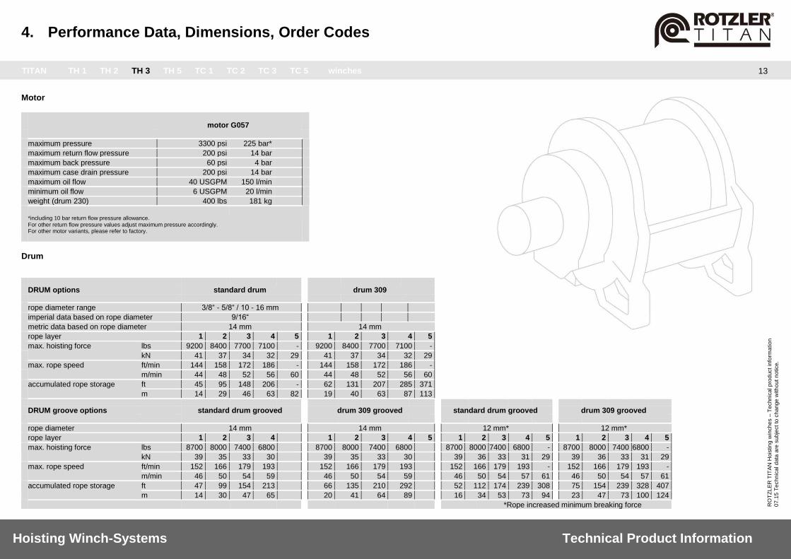
Drum
DRUM options standard drum drum 309
rope diameter range 3/8“ - 5/8“ / 10 - 16 mm
imperial data based on rope diameter 9/16“
metric data based on rope diameter 14 mm 14 mm
rope layer 1 2 3 4 5 1 2 3 4 5
max. hoisting force lbs 9200 8400 7700 7100 - 9200 8400 7700 7100 -
kN 41 37 34 32 29 41 37 34 32 29
max. rope speed ft/min 144 158 172 186 - 144 158 172 186 -
m/min 44 48 52 56 60 44 48 52 56 60
accumulated rope storage ft 45 95 148 206 - 62 131 207 285 371
m 14 29 46 63 82 19 40 63 87 113
DRUM groove options standard drum grooved drum 309 grooved standard drum grooved drum 309 grooved
rope diameter 14 mm 14 mm 12 mm* 12 mm*
rope layer 1 2 3 4 1 2 3 4 5 1 2 3 4 5 1 2 3 4 5
max. hoisting force lbs 8700 8000 7400 6800 8700 8000 7400 6800 8700 8000 7400 6800 - 8700 8000 7400 6800 -
kN 39 35 33 30 39 35 33 30 39 36 33 31 29 39 36 33 31 29
max. rope speed ft/min 152 166 179 193 152 166 179 193 152 166 179 193 - 152 166 179 193 -
m/min 46 50 54 59 46 50 54 59 46 50 54 57 61 46 50 54 57 61
accumulated rope storage ft 47 99 154 213 66 135 210 292 52 112 174 239 308 75 154 239 328 407
m 14 30 47 65 20 41 64 89 16 34 53 73 94 23 47 73 100 124
*Rope increased minimum breaking force

4. Performance Data, Dimensions, Order Codes
TITAN TH 1 TH 2 TH 3 TH 5 TC 1 TC 2 TC 3 TC 5 winches
14
Hoisting Winch-Systems Technical Product Information
RO
TZ
LE
R T
ITA
N H
ois
tin
g w
inch
es –
Te
chn
ica
l p
rod
uct in
form
atio
n
07
.15
Te
ch
nic
al d
ata
are
su
bje
ct
to c
ha
ng
e w
ith
ou
t n
otice.
Dimensions basic
... with options and accessories
motor G057 / standard drum A A
1 A
2 A
3 B B
1 C D E F G H I I
1 J K L
dimensions imperial (max.) – inches 19.5 20.4 23.5 22.6 20.7 21.1 17.0 12.7 14.2 10.8 0.8 9.0 11 11.6 16.7 8.6 0.8
dimensions metric (max.) – mm 495 517 597 575 526 536 433 323 360.7 275.3 20.4 228.5 279.4 295.4 423.4 218 20.3
motor G057 / 309 drum A A
1 A
2 A
3 B B
1 C D E F G H I I
1 J K L
dimensions imperial (max.) – inches 19.5 20.4 23.5 22.6 20.7 21.1 17.0 12.7 14.2 10.8 0.8 9.0 11 11.6 16.7 8.6 0.8
dimensions metric (max.) – mm 495 517 597 575 526 536 433 323 360.7 275.3 20.4 228.5 279.4 295.4 423.4 218 20.3
A1 = with MCD 1 / pressure roller
A2 = with MCD step 2, 3
A3 = with MCD step 4, 5
B1 = with MCD step 2, 3, 4 or 5
I1 = with grooves

4. Performance Data, Dimensions, Order Codes
TITAN TH 1 TH 2 TH 3 TH 5 TC 1 TC 2 TC 3 TC 5 winches
15
Hoisting Winch-Systems Technical Product Information
RO
TZ
LE
R T
ITA
N H
ois
tin
g w
inch
es –
Te
chn
ica
l p
rod
uct in
form
atio
n
07
.15
Te
ch
nic
al d
ata
are
su
bje
ct
to c
ha
ng
e w
ith
ou
t n
otice.
Order code
2.TH.30.CC.G057.00.0.0000.0.00.0.DIG
General Layout Without rope With rope
0 = No Roller / No MCD
1 = CC, Rope underwound
2 = CC, Rope overwound
3 = CW, Rope underwound
4 = CW, Rope overwound
Motor Layout
TITAN TH Ports Horizontal
Ports 60° CW
Ports 120° CW
Ports 180° CW
Ports 240° CW
Ports 300° CW
10
11
12
13
14
15
Motorports Case drain ports
cc = counter clockwise cw = clockwise M = motor
Version of Order Code
Construction TH = TITAN HOIST TC = TITAN COMPACT HOIST
Type 30 = TH3/TC3
30s = TH3/TC3 special
Rotation direction CW = Clockwise CC = Counter Clockwise
Motor displacement P040 = 40 cc Piston Motor (TC only) G057 = 57 cc Gear Motor (TH only) S = Special
Motor layout Position of Motor Ports and Case drain port see Details on the right
Drum width 0 = Standard drum 1 = 309 mm drum S = Special
Grooves 0000 = No grooves
0012 = Grooves for 12 mm rope 0014 = Grooves for 14 mm rope S = Special
MCD type 0 = No MCD
1 = MCD Step 1 2 = MCD Step 2 3 = MCD Step 3 4 = MCD Step 4 5 = MCD Step 5
Paint finish 00 = Primer 01 = White 02 = Black 03 = White + extra coat 04 = Black + extra coat S = Special
General layout Positioning of Rope Inlet and Rope Control System see Details on the right
Digital Code (DIG)
Binary Code
Parameter
1 0 Without Counterbalance Valve
1 With Counterbalance Valve (TC only)
2 0 Standard fasteners
1 Stainless fasteners
4 0 Without Pressure Roller
1 With Pressure Roller
8 0 Without External Brake Release
1 With External Brake Release (TC)
16 0 Without External Brake Release
1 With External Brake Release (TH)
32 0 With gear oil
1 Without gear oil
. .
. . . .
. .
.
4. Performance Data, Dimensions, Order Codes
TITAN TH 1 TH 2 TH 3 TH 5 TC 1 TC 2 TC 3 TC 5 winches
16
Hoisting Winch-Systems Technical Product Information
RO
TZ
LE
R T
ITA
N H
ois
tin
g w
inch
es –
Te
chn
ica
l p
rod
uct in
form
atio
n
07
.15
Te
ch
nic
al d
ata
are
su
bje
ct
to c
ha
ng
e w
ith
ou
t n
otice.
Motor motor G096 motor G0107
maximum pressure 2700 psi 185 bar* 2500 psi 175 bar*
maximum return flow pressure 200 psi 14 bar 200 psi 14 bar
maximum back pressure 175 psi 12 bar 175 psi 12 bar
maximum case drain pressure 200 psi 14 bar 200 psi 14 bar
maximum oil flow 69 USGPM 260 l/min 77 USGPM 289 l/min
minimum oil flow 7 USGPM 27 l/min 7 USGPM 27 l/min
weight (drum 309) 421 lbs 191 kg 421 lbs 191 kg
*including 10 bar return flow pressure allowance.
For other return flow pressure values adjust maximum pressure accordingly. For other motor variants, please refer to factory.
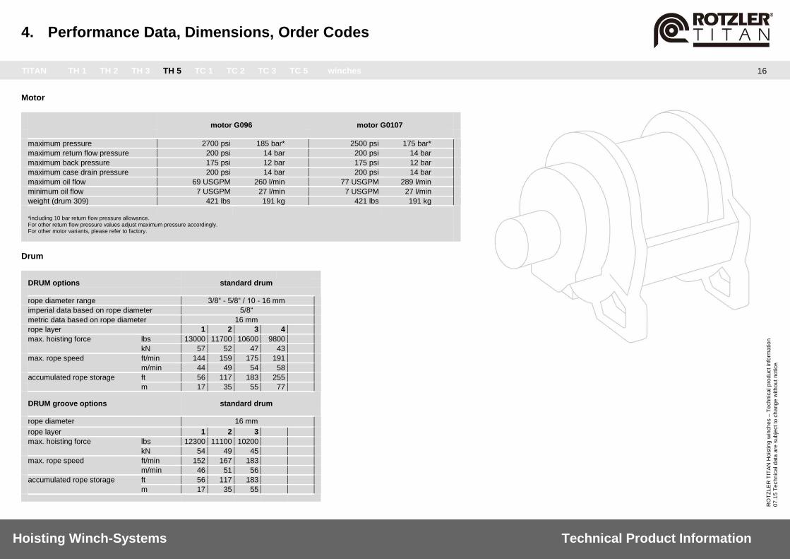
Drum DRUM options standard drum
rope diameter range 3/8“ - 5/8“ / 10 - 16 mm
imperial data based on rope diameter 5/8“
metric data based on rope diameter 16 mm
rope layer 1 2 3 4
max. hoisting force lbs 13000 11700 10600 9800
kN 57 52 47 43
max. rope speed ft/min 144 159 175 191
m/min 44 49 54 58
accumulated rope storage ft 56 117 183 255
m 17 35 55 77
DRUM groove options standard drum
rope diameter 16 mm
rope layer 1 2 3
max. hoisting force lbs 12300 11100 10200
kN 54 49 45
max. rope speed ft/min 152 167 183
m/min 46 51 56
accumulated rope storage ft 56 117 183
m 17 35 55
4. Performance Data, Dimensions, Order Codes
TITAN TH 1 TH 2 TH 3 TH 5 TC 1 TC 2 TC 3 TC 5 winches
17
Hoisting Winch-Systems Technical Product Information
RO
TZ
LE
R T
ITA
N H
ois
tin
g w
inch
es –
Te
chn
ica
l p
rod
uct in
form
atio
n
07
.15
Te
ch
nic
al d
ata
are
su
bje
ct
to c
ha
ng
e w
ith
ou
t n
otice.
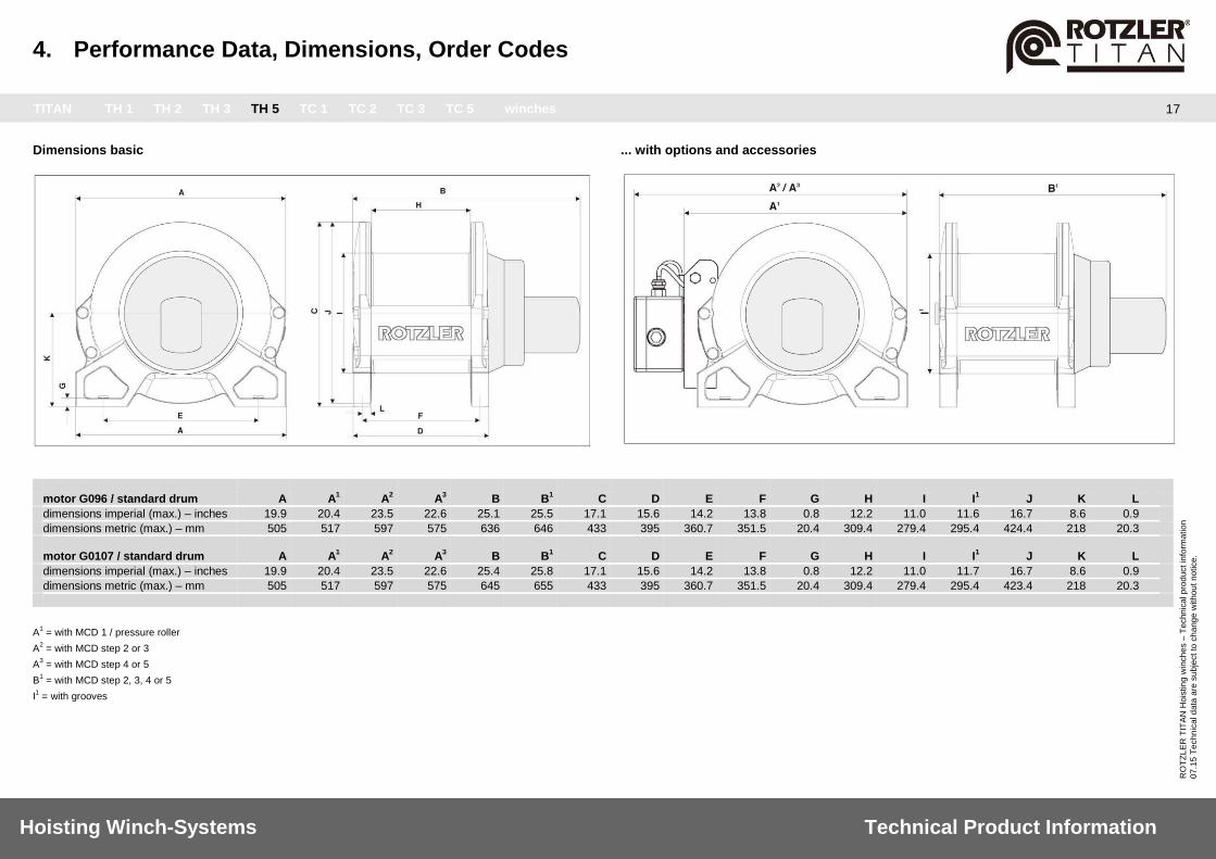
Dimensions basic
... with options and accessories
motor G096 / standard drum A A
1 A
2 A
3 B B
1 C D E F G H I I
1 J K L
dimensions imperial (max.) – inches 19.9 20.4 23.5 22.6 25.1 25.5 17.1 15.6 14.2 13.8 0.8 12.2 11.0 11.6 16.7 8.6 0.9
dimensions metric (max.) – mm 505 517 597 575 636 646 433 395 360.7 351.5 20.4 309.4 279.4 295.4 424.4 218 20.3
motor G0107 / standard drum A A
1 A
2 A
3 B B
1 C D E F G H I I
1 J K L
dimensions imperial (max.) – inches 19.9 20.4 23.5 22.6 25.4 25.8 17.1 15.6 14.2 13.8 0.8 12.2 11.0 11.7 16.7 8.6 0.9
dimensions metric (max.) – mm 505 517 597 575 645 655 433 395 360.7 351.5 20.4 309.4 279.4 295.4 423.4 218 20.3
A1 = with MCD 1 / pressure roller
A2 = with MCD step 2 or 3
A3 = with MCD step 4 or 5
B1 = with MCD step 2, 3, 4 or 5
I1 = with grooves
4. Performance Data, Dimensions, Order Codes
TITAN TH 1 TH 2 TH 3 TH 5 TC 1 TC 2 TC 3 TC 5 winches
18
Hoisting Winch-Systems Technical Product Information
RO
TZ
LE
R T
ITA
N H
ois
tin
g w
inch
es –
Te
chn
ica
l p
rod
uct in
form
atio
n
07
.15
Te
ch
nic
al d
ata
are
su
bje
ct
to c
ha
ng
e w
ith
ou
t n
otice.
Order code
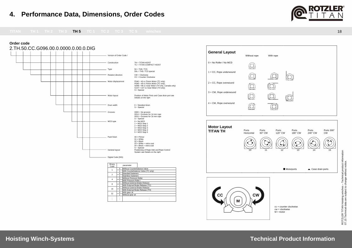
2.TH.50.CC.G096.00.0.0000.0.00.0.DIG
General Layout Without rope With rope
0 = No Roller / No MCD
1 = CC, Rope underwound
2 = CC, Rope overwound
3 = CW, Rope underwound
4 = CW, Rope overwound
Motor Layout TITAN TH Ports
Horizontal Ports 60° CW
Ports 120° CW
Ports 180° CW
Ports 240° CW
Ports 300° CW
10
11
12
13
14
15
Motorports Case drain ports
cc = counter clockwise cw = clockwise M = motor
Version of Order Code /
Construction TH = TITAN HOIST TC = TITAN COMPACT HOIST
Type 50 = TH5 / TC5 50s = TH5 / TC5 special
Rotation direction CW = Clockwise
CC = Counter Clockwise Motor displacement P040 = 40 cc Piston Motor (TC only)
P049 = 49 cc Piston Motor (TC only) G096 = 96 cc Gear Motor (TH only, Canada only) G107 = 107 cc Gear Motor (TH only) S = Special
Motor layout Position of Motor Ports and Case drain port see Details on the right
Drum width 0 = Standard drum S = Special
Grooves 0000 = No grooves 0014 = Grooves for 14 mm rope 0016 = Grooves for 16 mm rope S = Special
MCD type 0 = No MCD 1 = MCD Step 1 2 = MCD Step 2 3 = MCD Step 3 4 = MCD Step 4 5 = MCD Step 5
Paint finish 00 = Primer 01 = White 02 = Black 03 = White + extra coat 04 = Black + extra coat S = Special
General layout Positioning of Rope Inlet and Rope Control System see Details on the right
Digital Code (DIG)
Binary Code
parameter
1 0 Without Counterbalance Valve
1 With Counterbalance Valve (TC only)
2 0 Standard fasteners
1 Stainless fasteners
4 0 Without Pressure Roller
1 With Pressure Rolle r
8 0 Without External Brake Release
1 With External Brake Release (TC)
16 0 Without External Brake Release
1 With External Brake Release (TH)
32 0 With gear oil
1 Without gear oil
. . . . . .
. . .

4. Performance Data, Dimensions, Order Codes
TITAN TH 1 TH 2 TH 3 TH 5 TC 1 TC 2 TC 3 TC 5 winches
19
Hoisting Winch-Systems Technical Product Information
RO
TZ
LE
R T
ITA
N H
ois
tin
g w
inch
es –
Te
chn
ica
l p
rod
uct in
form
atio
n
07
.15
Te
ch
nic
al d
ata
are
su
bje
ct
to c
ha
ng
e w
ith
ou
t n
otice.
Motor motor G016
maximum pressure 3200 psi 220 bar*
maximum return flow pressure 300 psi 20 bar
maximum back pressure 75 psi 5 bar
maximum case drain pressure 300 psi 20 bar
maximum oil flow 11 USGPM 40 l/min
minimum oil flow 2.6 USGPM 10 l/min
weight (drum 153) 110 lbs 50 kg
*including 10 bar return flow pressure allowance.
For other return flow pressure values adjust maximum pressure accordingly. For other motor variants, please refer to factory.
Drum
DRUM options standard drum
rope diameter range 3/16“ - 3/8“ / 5 - 9 mm
imperial data based on rope diameter 5/16“
metric data based on rope diameter 8 mm
rope layer 1 2 3 4 5
max. hoisting force lbs kN
2800 12.5
2600 11.5
2400 10.5
2300 10
2100 9
max. rope speed ft/min m/min
128 39
141 43
151 46
164 50
174 53
accumulated rope storage ft m
33 10
69 21
108 33
148 45
190 58
DRUM groove options standard drum
rope diameter 8 mm
rope layer 1 2 3 4
max. hoisting force lbs kN
2600 11.5
2500 11
2300 10
2200 9.5
max. rope speed ft/min m/min
138 42
148 45
158 48
171 52
accumulated rope storage ft m
33 10
72 22
112 34
154 47

4. Performance Data, Dimensions, Order Codes
TITAN TH 1 TH 2 TH 3 TH 5 TC 1 TC 2 TC 3 TC 5 winches
20
Hoisting Winch-Systems Technical Product Information
RO
TZ
LE
R T
ITA
N H
ois
tin
g w
inch
es –
Te
chn
ica
l p
rod
uct in
form
atio
n
07
.15
Te
ch
nic
al d
ata
are
su
bje
ct
to c
ha
ng
e w
ith
ou
t n
otice.
Dimensions basic
... with options and accessories
motor G016 / standard drum A A
1 A
2 A
3 B B
1 C D E F G H I I
1 J K L
dimensions imperial (max.) – inches 12.6 13.5 16.6 15.8 11.4 11.6 11.0 8.5 9.0 7.3 0.5 6.1 7.0 7.4 10.7 5.6 0.6
dimensions metric (max.) – mm 320 342 422 400 290 300 280 215 230 184 12.7 153 178 187.8 270 141 15.5
A1 = with MCD 1 / pressure roller
A2 = with MCD step 2 or 3
A3 = with MCD step 4 or 5
B1 = with MCD step 2, 3, 4 or 5
I1 = with grooves

4. Performance Data, Dimensions, Order Codes
TITAN TH 1 TH 2 TH 3 TH 5 TC 1 TC 2 TC 3 TC 5 winches
21
Hoisting Winch-Systems Technical Product Information
RO
TZ
LE
R T
ITA
N H
ois
tin
g w
inch
es –
Te
chn
ica
l p
rod
uct in
form
atio
n
07
.15
Te
ch
nic
al d
ata
are
su
bje
ct
to c
ha
ng
e w
ith
ou
t n
otice.
Order code
2.TC.10.CC.G016.00.0.0000.0.00.0.DIG
General Layout Without rope With rope
0 = No Roller / No MCD
1 = CC, Rope underwound
2 = CC, Rope overwound
3 = CW, Rope underwound
4 = CW, Rope overwound
Motor Layout TITAN TC Motor port
left side Motor port on top
Motor port right side
Motor port on bottom
End Cover standard (Case Drain port on top)
00
01
02
03
End Cover rotated (Case Drain port on bottom)
04
05
06
07
Motorports Case drain ports
cc = counter clockwise cw = clockwise M = motor
Version of Order Code
Construction TH = TITAN HOIST TC = TITAN COMPACT HOIST
Type 10 = TH1/TC1
10s = TH1/TC1 special Rotation direction CW = Clockwise
CC = Counter Clockwise Motor displacement G016 = 16 cc Gear Motor
S = Special
Motor layout Position of Motor Ports and Case drain port see Details on the right
Drum width 0 = Standard drum S = Special
Grooves 0000 = No grooves 0008 = Grooves for 8 mm rope S = Special
MCD type 0 = No MCD 1 = MCD Step 1 2 = MCD Step 2 (TC only) 3 = MCD Step 3 (TC only) 4 = MCD Step 4 (TC only) 5 = MCD Step 5 (TC only)
Paint finish 00 = Primer 01 = White 02 = Black 03 = White + extra coat 04 = Black + extra coat S = Special
General layout Positioning of Rope Inlet and Rope Control System see Details on the right
Digital Code (DIG)
Binary Code
parameter
1 0 Without Counterbalance Valve
1 With Counterbalance Valve (TC only)
2 0 Standard fasteners
1 Stainless fasteners
4 0 Without Pressure Roller
1 With Pressure Roller
8 0 Without External Brake Release
1 With External Brake Release (TC)
16 0 Without External Brake Release
1 With External Brake Release (TH)
32 0 With gear oil
1 Without gear oil
.
. . . . .
.
. .

4. Performance Data, Dimensions, Order Codes
TITAN TH 1 TH 2 TH 3 TH 5 TC 1 TC 2 TC 3 TC 5 winches
22
Hoisting Winch-Systems Technical Product Information
RO
TZ
LE
R T
ITA
N H
ois
tin
g w
inch
es –
Te
chn
ica
l p
rod
uct in
form
atio
n
07
.15
Te
ch
nic
al d
ata
are
su
bje
ct
to c
ha
ng
e w
ith
ou
t n
otice.
Motor motor G036
maximum pressure 2800 psi 190 bar*
maximum return flow pressure 300 psi 20 bar
maximum back pressure 75 psi 5 bar
maximum case drain pressure 300 psi 20 bar
maximum oil flow 26 USGPM 97 l/min
minimum oil flow 6 USGMPM 20 l/min
weight (drum 180) ca. 165 lbs ca. 75 kg
weight (drum 252) ca. 210 lbs ca. 95 kg
*including 10 bar return flow pressure allowance.
For other return flow pressure values adjust maximum pressure accordingly. For other motor variants, please refer to factory.
Drum
DRUM options standard drum
rope diameter range 1/4“ - 1/2“ / 6 - 12 mm
imperial data based on rope diameter 3/8“
metric data based on rope diameter 10 mm
rope layer 1 2 3 4 5
max. hoisting force lbs 6000 5400 5000 4600 4300
kN 26 24 22 20 19
max. rope speed ft/min 132 144 157 169 182
m/min 40 44 48 52 56
accumulated rope storage ft 36 76 119 165 214
m 10 22 35 49 62
DRUM groove options standard drum drum 252 (TC 2L)
rope diameter 10 mm 10 mm
rope layer 1 2 3 4 1 2 3 4
max. hoisting force lbs 5700 5200 4800 4400 5700 5200 4800 4400
kN 25 23 21 20 25 23 21 20
max. rope speed ft/min 139 152 165 178 139 152 165 178
m/min 42 46 50 54 42 46 50 54
accumulated rope storage ft 35 74 116 161 51 106 165 229
m 10 22 34 48 15 32 50 69

4. Performance Data, Dimensions, Order Codes
TITAN TH 1 TH 2 TH 3 TH 5 TC 1 TC 2 TC 3 TC 5 winches
23
Hoisting Winch-Systems Technical Product Information
RO
TZ
LE
R T
ITA
N H
ois
tin
g w
inch
es –
Te
chn
ica
l p
rod
uct in
form
atio
n
07
.15
Te
ch
nic
al d
ata
are
su
bje
ct
to c
ha
ng
e w
ith
ou
t n
otice.
Dimensions basic
... with options and accessories
motor G036 / standard drum A A
1 A
2 A
3 B B
1 C D E F G H I I
1 J K L
dimensions imperial (max.) – inches 13.8 15.0 18.3 17.3 14.8 15.2 11.8 10.1 9.7 8.6 0.6 7.2 7.5 7.7 11.5 6.0 0.7
dimensions metric (max.) – mm 350 380 465 440 375 385 300 256 247.5 219 14.0 180.0 190.5 200.5 292 152 17.6
motor G036 / drum 252 (TC 2L) A A
1 A
2 A
3 B B
1 C D E F G H I I
1 J K L
dimensions imperial (max.) – inches 13.8 15.0 18.3 17.3 17.7 18.1 11.8 13.0 9.7 11.6 0.6 9.9 N/A 7.7 11.5 6.0 0.7
dimensions metric (max.) – mm 350 380 465 440 450 460 300 330 247.5 292.5 14.0 252 N/A 200.5 292 152 17.6
A1 = with MCD 1 / pressure roller
A2 = with MCD step 2 or 3
A3 = with MCD step 4 or 5
B1 = with MCD step 2, 3, 4 or 5
I1 = with grooves

4. Performance Data, Dimensions, Order Codes
TITAN TH 1 TH 2 TH 3 TH 5 TC 1 TC 2 TC 3 TC 5 winches
24
Hoisting Winch-Systems Technical Product Information
RO
TZ
LE
R T
ITA
N H
ois
tin
g w
inch
es –
Te
chn
ica
l p
rod
uct in
form
atio
n
07
.15
Te
ch
nic
al d
ata
are
su
bje
ct
to c
ha
ng
e w
ith
ou
t n
otice.
Order code
2.TC.20.CC.G036.00.0.0000.0.00.0.DIG
General Layout Without rope With rope 0 = No Roller / No MCD
1 = CC, Rope underwound
2 = CC, Rope overwound
3 = CW, Rope underwound
4 = CW, Rope overwound
Motor Layout TITAN TC Motor port
left side Motor port on top
Motor port right side
Motor port on bottom
00 01 02 03
Motorports Case drain ports
cc = counter clockwise cw = clockwise M = motor
Version of Order Code
Construction TH = TITAN HOIST TC = TITAN COMPACT HOIST
Type 20 = TH2/TC2 20s = TH2/TC2 special
Rotation direction CW = Clockwise
CC = Counter Clockwise
Motor displacement G019 = 19 cc Gear Motor (TH only) G031 = 31 cc Gear Motor (TH only) G036 = 36 cc Gear Motor (TC only) S = Special
Motor layout Position of Motor Ports and Case drain port see Details on the right
Drum width 0 = Standard drum 1 = 252 mm drum (TC only) S = Special
Grooves 0000 = No grooves
0012 = Grooves for 12 mm rope 0010 = Grooves for 10 mm rope S = Special
MCD type 0 = No MCD 1 = MCD Step 1 2 = MCD Step 2 (TC only) 3 = MCD Step 3 (TC only) 4 = MCD Step 4 (TC only) 5 = MCD Step 5 (TC only)
Paint finish 00 = Primer 01 = White 02 = Black 03 = White + extra coat 04 = Black + extra coat S = Special
General layout Positioning of Rope Inlet and Rope Control
System see Details on the right
Digital Code (DIG)
Binary Code
Parameter
1 0 Without Counterbalance Valve
1 With Counterbalance Valve (TC only)
2 0 Standard fasteners
1 Stainless fasteners
4 0 Without Pressure Roller
1 With Pressure Roller
8 0 Without External Brake Release
1 With External Brake Release (TC)
16 0 Without External Brake Release
1 With External Brake Release (TH)
32 0 With gear oil
1 Without gear oil
. .
. . . .
. .
.

4. Performance Data, Dimensions, Order Codes
TITAN TH 1 TH 2 TH 3 TH 5 TC 1 TC 2 TC 3 TC 5 winches
25
Hoisting Winch-Systems Technical Product Information
RO
TZ
LE
R T
ITA
N H
ois
tin
g w
inch
es –
Te
chn
ica
l p
rod
uct in
form
atio
n
07
.15
Te
ch
nic
al d
ata
are
su
bje
ct
to c
ha
ng
e w
ith
ou
t n
otice.
Motor motor P040 motor P040 / drum 309
maximum pressure 4100 psi 280 bar* 4100 psi 280 bar *
maximum return flow pressure 200 psi 14 bar 200 psi 14 bar
maximum back pressure 60 psi 4 bar 60 psi 4 bar
maximum case drain pressure 25 psi 1.7 bar 25 psi 1,7 bar
maximum oil flow 27 USGPM 100 l/min 27 USGPM 100 l/min
minimum oil flow 6 USGPM 20 l/min 6 USGPM 20 l/min
weight (drum 229) 373 lbs 169 kg 421 lbs 191 kg
*including 10 bar return flow pressure allowance.
For other return flow pressure values adjust maximum pressure accordingly. For other motor variants, please refer to factory.
Drum
DRUM options standard drum drum 309
rope diameter range 3/8“ - 5/8“ / 10 - 16 mm 3/8“ - 5/8“ / 10 - 16 mm
imperial data based on rope diameter 9/16“ 9/16“
metric data based on rope diameter 14 mm 14 mm
rope layer 1 2 3 4 5 1 2 3 4 5
max. hoisting force lbs 9200 8400 7700 7100 6600 9200 8400 7700 7100 6700
kN 41 37 34 32 29 41 37 34 32 29
max. rope speed ft/min 144 158 172 186 197 144 158 172 186 206
m/min 44 48 52 56 60 44 48 52 56 62
accumulated rope storage ft 45 95 148 206 270 63 132 206 286 371
m 14 29 46 63 82 19 40 63 87 113
DRUM groove options standard drum grooved drum 309 grooved standard drum grooved drum 309 grooved
rope diameter 14 mm 14 mm 12 mm* 12 mm*
rope layer 1 2 3 4 1 2 3 4 1 2 3 4 5 1 2 3 4 5
max. hoisting force lbs 8700 8000 7400 6800 8700 8000 7400 6800 8700 8000 7400 6800 8700 8000 7400 6800
kN 39 35 33 30 39 35 33 30 39 36 33 31 29 39 36 33 31 29
max. rope speed ft/min 152 166 179 193 152 166 179 193 152 166 179 193 152 166 179 193
m/min 46 50 54 59 46 50 54 59 46 50 54 57 61 46 50 54 57 61
accumulated rope storage ft 47 99 154 213 65 136 211 292 52 112 174 239 308 75 154 239 328 407
m 14 30 47 65 20 41 64 89 16 34 53 73 94 23 47 73 100 129
*Rope increased minimum breaking force

4. Performance Data, Dimensions, Order Codes
TITAN TH 1 TH 2 TH 3 TH 5 TC 1 TC 2 TC 3 TC 5 winches
26
Hoisting Winch-Systems Technical Product Information
RO
TZ
LE
R T
ITA
N H
ois
tin
g w
inch
es –
Te
chn
ica
l p
rod
uct in
form
atio
n
07
.15
Te
ch
nic
al d
ata
are
su
bje
ct
to c
ha
ng
e w
ith
ou
t n
otice.
Dimensions basic
... with options and accessories
motor P040 / standard drum A A
1 A
2 A
3 B B
1 C D E F G H I I
1 J K L
dimensions imperial (max.) – inches 19.5 20.4 23.5 22.6 17.1 17.5 17.1 12.7 14.2 10.8 0.8 9 11 11.6 16.7 8.6 0.8
dimensions metric (max.) – mm 495 517 597 575 435 445 433 323 360.7 275.3 20.3 228.5 279.4 295.4 423.4 218 20.3
motor P040/49 / 309 drum TC 3 L A A
1 A
2 A
3 B B
1 C D E F G H I I
1 J K L
dimensions imperial (max.) – inches 19.9 20.4 23.5 22.6 20.1 20.5 17.1 15.6 14.2 13.8 0.8 12.2 11 11.7 16.7 8.6 0.8
dimensions metric (max.) – mm 505 517 597 575 510 520 433 395 360.7 351.5 20.4 309.4 279.4 295.4 423.4 218 20.3
A1 = with MCD 1 / pressure roller
A2 = with MCD step 2 or 3
A3 = with MCD step 4 or 5
B1 = with MCD step 2, 3, 4 or 5
I1 = with grooves

4. Performance Data, Dimensions, Order Codes
TITAN TH 1 TH 2 TH 3 TH 5 TC 1 TC 2 TC 3 TC 5 winches
27
Hoisting Winch-Systems Technical Product Information
RO
TZ
LE
R T
ITA
N H
ois
tin
g w
inch
es –
Te
chn
ica
l p
rod
uct in
form
atio
n
07
.15
Te
ch
nic
al d
ata
are
su
bje
ct
to c
ha
ng
e w
ith
ou
t n
otice.
Order code
2.TC.30.CC.P040.00.0.0000.0.00.0.DIG
General Layout Without rope With rope 0 = No Roller / No MCD
1 = CC, Rope underwound
2 = CC, Rope overwound
3 = CW, Rope underwound
4 = CW, Rope overwound
Motor Layout TITAN TC Motor port
left side Motor port on top
Motor port right side
Motor port on bottom
00
01
02
03
Motorports Case drain ports
cc = counter clockwise cw = clockwise M = motor
Version of Order Code /
Construction TH = TITAN HOIST TC = TITAN COMPACT HOIST
Type 30 = TH3 / TC3 30s = TH3 / TC3 special
Rotation direction CW = Clockwise CC = Counter Clockwise
Motor displacement P040 = 40 cc Piston Motor (TC only) P057 = 57 cc Gear Motor (TH only) S = Special
Motor layout Position of Motor Ports and Case drain port see Details on the right
Drum width 0 = Standard drum 1 = 309 mm drum S = Special
Grooves 0000 = No grooves
0012 = Grooves for 12 mm rope 0014 = Grooves for 14 mm rope S = Special
MCD type 0 = No MCD 1 = MCD Step 1 2 = MCD Step 2 3 = MCD Step 3 4 = MCD Step 4 5 = MCD Step 5
Paint finish 00 = Primer 01 = White 02 = Black 03 = White + extra coat 04 = Black + extra coat S = Special
General layout Positioning of Rope Inlet and Rope Control System see Details on the right
Digital Code (DIG)
Binary Code
parameter
1 0 Without Counterbalance Valve
1 With Counterbalance Valve (TC only)
2 0 Standard fasteners
1 Stainless fasteners
4 0 Without Pressure Roller
1 With Pressure Roller
8 0 Without External Brake Release
1 With External Brake Release (TC)
16 0 Without External Brake Release
1 With External Brake Release (TH)
32 0 With gear oil
1 Without gear oil
. .
. . . .
. .
.

4. Performance Data, Dimensions, Order Codes
TITAN TH 1 TH 2 TH 3 TH 5 TC 1 TC 2 TC 3 TC 5 winches
28
Hoisting Winch-Systems Technical Product Information
RO
TZ
LE
R T
ITA
N H
ois
tin
g w
inch
es –
Te
chn
ica
l p
rod
uct in
form
ation
07
.15
Te
ch
nic
al d
ata
are
su
bje
ct
to c
ha
ng
e w
ith
ou
t n
otice.
Motor
motor P049
maximum pressure 4700 psi 320 bar *
maximum return flow pressure 200 psi 14 bar
maximum back pressure 75 psi 5 bar
maximum pressure drain line 25 psi 1,7 bar
maximum oil flow 32 USGPM 120 l/min
minimum oil flow 3 USGPM 11 l/min
weight (drum 309) 421 lbs 191 kg
* including 10 bar return flow pressure allowance. For other return flow pressure values adjust maximum pressure accordingly. For other motor variants, please refer to factory.
Drum
DRUM options motor P049 / standard drum
rope diameter range 3/8“ - 5/8“ / 10 - 16 mm
data based on rope diameter 5/8“ / 16 mm
rope layer 1 2 3 4
max. hoisting force lbs 13000 11700 10600 9800
kN 57 52 47 43
max. rope speed ft/min 144 159 175 191
m/min 44 49 54 58
accumulated rope storage ft 56 117 183 255
m 17 35 55 77
DRUM groove options motor P049 / standard drum
data based on rope diameter 16 mm 14 mm*
rope layer 1 2 3 1 2 3 4
max. hoisting force lbs 12300 11100 10200 12300 11200 10400 9600
kN 54 49 45 54 50 46 43
max. rope speed ft/min 152 167 183 152 166 179 193
m/min 46 51 55 46 50 54 59
accumulated rope storage ft 56 117 183 65 136 211 292
m 17 35 55 20 41 64 89
* increased minimum breaking force
4. Performance Data, Dimensions, Order Codes
TITAN TH 1 TH 2 TH 3 TH 5 TC 1 TC 2 TC 3 TC 5 winches
29
Hoisting Winch-Systems Technical Product Information
RO
TZ
LE
R T
ITA
N H
ois
tin
g w
inch
es –
Te
chn
ica
l p
rod
uct in
form
ation
07
.15
Te
ch
nic
al d
ata
are
su
bje
ct
to c
ha
ng
e w
ith
ou
t n
otice.
Dimensions basic
... with options and accessories
motor P040/49 / standard drum A A
1 A
2 A
3 B B
1 C D E F G H I I
1 J K L
dimensions imperial (max.) – inches 19.9 20.4 23.5 22.6 20.1 20.5 17.1 15.6 14.2 13.8 0.8 12.2 11 11.7 16.7 8.6 0.8
dimensions metric (max.) – mm 505 517 597 575 510 520 433 395 360.7 351.5 20.4 309.4 279.4 295.4 423.4 218 20.3
A1 = with MCD 1 / pressure roller
A2 = with MCD step 2 or 3
A3 = with MCD step 4 or 5
B1 = with MCD step 2, 3, 4 or 5
I1 = with grooves

4. Performance Data, Dimensions, Order Codes
TITAN TH 1 TH 2 TH 3 TH 5 TC 1 TC 2 TC 3 TC 5 winches
30
Hoisting Winch-Systems Technical Product Information
RO
TZ
LE
R T
ITA
N H
ois
tin
g w
inch
es –
Te
chn
ica
l p
rod
uct in
form
ation
07
.15
Te
ch
nic
al d
ata
are
su
bje
ct
to c
ha
ng
e w
ith
ou
t n
otice.
Order code
2.TC.50.CC.P049.00.0.0000.0.00.0.DIG
General Layout Without rope With rope
0 = No Roller / No MCD
1 = CC, Rope underwound
2 = CC, Rope overwound
3 = CW, Rope underwound
4 = CW, Rope overwound
Motor Layout TITAN TC Motor port
left side
Motor port
on top Motor port right side
Motor port on bottom
00
01
02
03
Motorports Case drain ports
cc = counter clockwise cw = clockwise M = motor
Version of Order Code /
Construction TH = TITAN HOIST TC = TITAN COMPACT HOIST
Type 50 = TH5 / TC5 50s = TH5 / TC5 special
Rotation direction CW = Clockwise CC = Counter Clockwise
Motor displacement P040 = 40 cc Piston Motor (TC only) P049 = 49 cc Piston Motor (TC only) G096 = 96 cc Gear Motor (TH only) G107 = 107 cc Gear Motor (TH only) S = Special
Motor layout Position of Motor Ports and Case drain port see Details on the right
Drum width 0 = Standard drum S = Special
Grooves 0000 = No grooves 0014 = Grooves for 14 mm rope 0016 = Grooves for 16 mm rope S = Special
MCD type 0 = No MCD 1 = MCD Step 1 2 = MCD Step 2 3 = MCD Step 3 4 = MCD Step 4 5 = MCD Step 5
Paint finish 00 = Primer 01 = White 02 = Black 03 = White + extra coat 04 = Black + extra coat S = Special
General layout Positioning of Rope Inlet and Rope Control System see Details on the right
Digital Code (DIG)
Binary Code
parameter
1 0 Without Counterbalance Valve
1 With Counterbalance Valve (TC only)
2 0 Standard fasteners
1 Stainless fasteners
4 0 Without Pressure Roller
1 With Pressure Roller
8 0 Without External Brake Release
1 With External Brake Release (TC)
16 0 Without External Brake Release
1 With External Brake Release (TH)
32 0 With gear oil
1 Without gear oil
. .
. . . .
. .
.

5. Installation Instructions
TITAN TH 1 TH 2 TH 3 TH 5 TC 1 TC 2 TC 3 TC 5 winches
31
Hoisting Winch-Systems Technical Product Information
RO
TZ
LE
R T
ITA
N H
ois
tin
g w
inch
es –
Te
chn
ica
l p
rod
uct in
form
atio
n
07
.15
Te
ch
nic
al d
ata
are
su
bje
ct
to c
ha
ng
e w
ith
ou
t n
otice.
Mechanic installation Fig. 1 Bolt winch on fixing plate (2) by means of screws
(1) (size, quality and tightening moment see Fig. 2). The fixing plate (2) must be sufficiently dimensioned, in order to take up the forces at winch operation. The fixing surface (A) must be free of rust, tinder, oil and grease. The flatness tolerance of the surface is 0.5 mm. You can see the thickness of the base frame (measure X) in the chart in Fig. 2. Attention: Only mount winch in horizontal axis (H). Fig. 2 Chart for the screws which have to be used in each
case. Fig. 3 Installation example - installed on knuckle boom
crane. Fig. 4 Not allowed installation positions.
Fig. 5 In order to guarantee a correct rope spooling, the
distance measure (A) from the middle of the winch (1) up to the first firm pulley (2) has to be chosen in such a way, that a deflection angle of a = 1 - 2° is kept. The formula we suggest is: 28 x B > A > 14 x B Fig. 6 Shows direction of rotation with view to the motor
side (M). Pay attention to direction of rotation! When installing the winch, please note whether the direction of rotation is clockwise (CW) or counter clockwise (CC).
Mounting screws
winch type quantity size quality tightening torque
meas. X
[Nm] [mm]
TITAN TH 1 4 M12 8.8 79 14,5
TITAN TH 2 4 M16 8.8 195 15
TITAN TH 3 4 M20 8.8 395 20
TITAN TH 5 4 M22 8.8 540 20
TITAN TC 1 4 M12 8.8 79 14,5
TITAN TC 2 4 M16 8.8 195 15
TITAN TC 3 4 M20 8.8 395 20
TITAN TC 5 4 M22 8.8 540 20
Stainless steel fasteners (optional)
TITAN TH 1 4 M12 –80 73 14,5
TITAN TH 2 4 M16 –80 180 15
TITAN TH 3 4 M20 -80 360 20
TITAN TH 5 4 M22 -80 480 20
TITAN TC 1 4 M12 –80 73 14,5
TITAN TC 2 4 M16 –80 180 15
TITAN TC 3 4 M20 -80 360 20
TITAN TC 5 4 M22 -80 480 20
2
5. Installation Instructions
TITAN TH 1 TH 2 TH 3 TH 5 TC 1 TC 2 TC 3 TC 5 winches
32
Hoisting Winch-Systems Technical Product Information
RO
TZ
LE
R T
ITA
N H
ois
tin
g w
inch
es –
Te
chn
ica
l p
rod
uct in
form
atio
n
07
.15
Te
ch
nic
al d
ata
are
su
bje
ct
to c
ha
ng
e w
ith
ou
t n
otice.
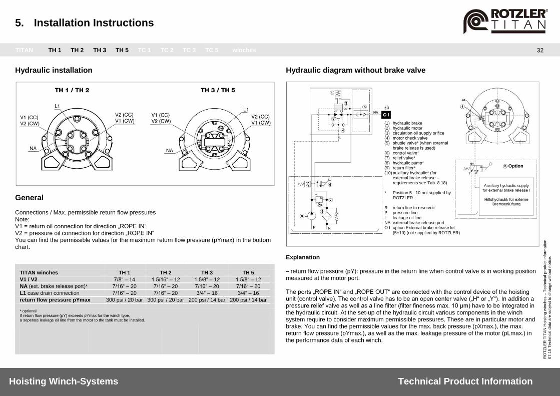
Hydraulic installation
General Connections / Max. permissible return flow pressures Note: V1 = return oil connection for direction „ROPE IN“ V2 = pressure oil connection for direction „ROPE IN“ You can find the permissible values for the maximum return flow pressure (pYmax) in the bottom chart. TITAN winches TH 1 TH 2 TH 3 TH 5
V1 / V2 7/8“ – 14 1 5/16“ – 12 1 5/8“ – 12 1 5/8“ – 12
NA (ext. brake release port)* 7/16“ – 20 7/16“ – 20 7/16“ – 20 7/16“ – 20
L1 case drain connection 7/16“ – 20 7/16“ – 20 3/4“ – 16 3/4“ – 16
return flow pressure pYmax 300 psi / 20 bar 300 psi / 20 bar 200 psi / 14 bar 200 psi / 14 bar
* optional
If return flow pressure (pY) exceeds pYmax for the winch type, a seperate leakage oil line from the motor to the tank must be installed.
Hydraulic diagram without brake valve
Explanation
– return flow pressure (pY): pressure in the return line when control valve is in working position measured at the motor port. The ports „ROPE IN“ and „ROPE OUT“ are connected with the control device of the hoisting unit (control valve). The control valve has to be an open center valve („H“ or „Y“). In addition a pressure relief valve as well as a line filter (filter fineness max. 10 μm) have to be integrated in the hydraulic circuit. At the set-up of the hydraulic circuit various components in the winch system require to consider maximum permissible pressures. These are in particular motor and brake. You can find the permissible values for the max. back pressure (pXmax.), the max. return flow pressure (pYmax.), as well as the max. leakage pressure of the motor (pLmax.) in the performance data of each winch.
(1) hydraulic brake (2) hydraulic motor (3) circulation oil supply orifice (4) motor check valve (5) shuttle valve* (when external
brake release is used) (6) control valve* (7) relief valve* (8) hydraulic pump* (9) return filter* (10) auxiliary hydraulic* (for
external brake release – requirements see Tab. 8.18)
* Position 5 - 10 not supplied by
ROTZLER R return line to reservoir P pressure line L leakage oil line NA external brake release port O I option External brake release kit
(5+10) (not supplied by ROTZLER)
Auxiliary hydraulic supply
for external brake release /
Hilfshydraulik für externe Bremsenlüftung
Option
5. Installation Instructions
TITAN TH 1 TH 2 TH 3 TH 5 TC 1 TC 2 TC 3 TC 5 winches
33
Hoisting Winch-Systems Technical Product Information
RO
TZ
LE
R T
ITA
N H
ois
tin
g w
inch
es –
Te
chn
ica
l p
rod
uct in
form
atio
n
07
.15
Te
ch
nic
al d
ata
are
su
bje
ct
to c
ha
ng
e w
ith
ou
t n
otice.
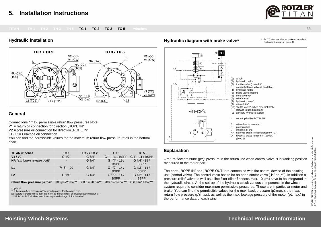
Hydraulic installation
General Connections / max. permissible return flow pressures Note: V1 = return oil connection for direction „ROPE IN“ V2 = pressure oil connection for direction „ROPE IN“ L1 / L2= Leakage oil connection You can find the permissible values for the maximum return flow pressure rates in the bottom chart. TITAN winches TC 1 TC 2 / TC 2L TC 3 TC 5
V1 / V2 G 1/2“ G 3/4“ G 1“ - 11 / BSPP G 1“ - 11 / BSPP
NA (ext. brake release port)* - G 1/4“ G 1/4“ - 19 / BSPP
G 1/4“ - 19 / BSPP
L1 7/16“ – 20 G 1/4“ G 1/2“ - 14 / BSPP
G 1/2“ - 14 / BSPP
L2 G 1/4“ G 1/4“ G 1/2“ - 14 / BSPP
G 1/2“ - 14 / BSPP
return flow pressure pYmax. 300 psi/20 bar** 300 psi/20 bar** 200 psi/14 bar*** 200 bar/14 bar*** * optional
** If the return flow pressure (pY) exceeds pYmax for the winch type, a separate leakage oil line from the motor to the tank must be installed (see chapter 5). *** All TC 3 / TC5 winches must have seperate leakage oil line installed.
Hydraulic diagram with brake valve* * for TC winches without brake valve refer to hydraulic diagram on page 32
Explanation – return flow pressure (pY): pressure in the return line when control valve is in working position measured at the motor port. The ports „ROPE IN“ and „ROPE OUT“ are connected with the control device of the hoisting unit (control valve). The control valve has to be an open center valve („H“ or „Y“). In addition a pressure relief valve as well as a line filter (filter fineness max. 10 μm) have to be integrated in the hydraulic circuit. At the set-up of the hydraulic circuit various components in the winch system require to consider maximum permissible pressures. These are in particular motor and brake. You can find the permissible values for the max. back pressure (pXmax.), the max. return flow pressure (pYmax.), as well as the max. leakage pressure of the motor (pLmax.) in the performance data of each winch.
(1) winch (2) hydraulic brake (3) throttle valve (closed, if
counterbalance valve is available) (4) hydraulic motor (5) brake valve (option) (6) control valve* (7) relief valve* (8) hydraulic pump* (9) return filter* (10) shuttle valve* (when external brake
release is used) (option) (11) auxiliary hydraulic system * not supplied by ROTZLER R return line to reservoir P pressure line L leakage oil line NA external brake release port (only TC) OI External brake release kit (option)
(10+11)

5. Installation Instructions
TITAN TH 1 TH 2 TH 3 TH 5 TC 1 TC 2 TC 3 TC 5 winches
34
Hoisting Winch-Systems Technical Product Information
RO
TZ
LE
R T
ITA
N H
ois
tin
g w
inch
es –
Te
chn
ica
l p
rod
uct in
form
atio
n
07
.15
Te
ch
nic
al d
ata
are
su
bje
ct
to c
ha
ng
e w
ith
ou
t n
otice.
Overview TITAN winches TH 2 TH 3 TH 5 TC 1 TC 2 TC 3 TC 5
Options
MCD Step 1 x x x x x x x
MCD Step 2 x x x x x
MCD Step 3 x x x x x
MCD Step 4 x x x x x
MCD Step 5 x x x x x
Stainless Steel Fastness x x x x x x x
External Brake Release x x x x* x x x
Counterbalance Valve x x x x
Pressure Roller x x x x x x x
Grooved Drums x x x x x x x
* for configurations without counterbalance valve only
MCD (Measuring Control Device) Description
By measuring the current gear torque (static and dynamic) all possible operating states are identified to rule out overloading. The ROTZLER MCD delivers an exact linear output signal, proportional to the load torque. In addition, the MCD issues an electrical signal when the rope reaches the prescribed last three safety windings. The linear signal delivered from the MCD electronics may be used for a variety of applications. The ROTZLER MCD are exclusively used for ROTZLER TITAN winches. The use as determined is the overload sensor and rope sensor of ROTZLER TITAN winches. The use as determined also includes the related equipment, manufacturer’s recommendations regarding installation, operation and maintenance. Temperature range
The ROTZLER TITAN electronics are designed for operation in a temperature range/ambient temperature of -30° C up to +60° C. Please contact us regarding extreme temperatures, vibrations, jerks, sand, dust, sea water or any other extreme environment condition.
Function
The ROTZLER MCD is available in different steps (MCD-step 1-5): MCD step 1
- is a rope end sensor at drum rotation direction “ROPE OUT” MCD step 2
- is an overload sensor (1-point sensoring) in winch direction “ROPE IN” which is attached in the gear. This sensor serves as overload protection of the winch and for the protection of the operator. MCD step 3
- is an additional overload sensor in winch direction “ROPE IN”. This option can be used for adjusting a second sensoring point (2-point sensoring). For example: overload protection of the hoisting device by extending the jib manually. As soon as the allowable load is exceeded, a signal is given by the electronics system (MCD Step 2 and 3). This signal can be used via the hoist security device to switch off the system. MCD step 2: Signal = 1,15 x rated load MCD step 3: Signal 1 = 1,15 x rated load MCD step 3: Signal 2 >_ 0,2 x rated load MCD step 4
- combined rope end and torque signal (signal 1). Signal 2 without function. MCD step 5
- separate rope end (signal 1) and torque (signal 2) signals. To ensure correct winch operation, a suitable electronic control system capable of processing the MCD output signals, must be provided.
6. Options and Accessories
TITAN TH 1 TH 2 TH 3 TH 5 TC 1 TC 2 TC 3 TC 5 winches
35
Hoisting Winch-Systems Technical Product Information
RO
TZ
LE
R T
ITA
N H
ois
tin
g w
inch
es –
Te
chn
ica
l p
rod
uct in
form
atio
n
07
.15
Te
ch
nic
al d
ata
are
su
bje
ct
to c
ha
ng
e w
ith
ou
t n
otice.
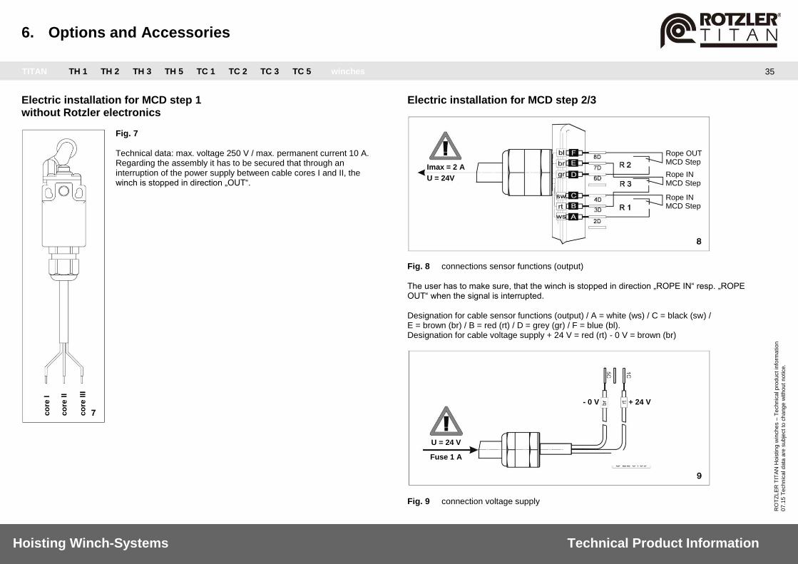
Electric installation for MCD step 1 without Rotzler electronics
Fig. 7
Technical data: max. voltage 250 V / max. permanent current 10 A. Regarding the assembly it has to be secured that through an interruption of the power supply between cable cores I and II, the winch is stopped in direction „OUT“.
Electric installation for MCD step 2/3
Fig. 8 connections sensor functions (output)
The user has to make sure, that the winch is stopped in direction „ROPE IN“ resp. „ROPE OUT“ when the signal is interrupted. Designation for cable sensor functions (output) / A = white (ws) / C = black (sw) / E = brown (br) / B = red (rt) / D = grey (gr) / F = blue (bl). Designation for cable voltage supply + 24 V = red (rt) - 0 V = brown (br)
Fig. 9 connection voltage supply
Imax = 2 A
U = 24V
Rope OUT MCD Step
Rope IN MCD Step
Rope IN MCD Step
U = 24 V
Fuse 1 A
+ 24 V - 0 V
co
re I
co
re II
co
re III
6. Options and Accessories
TITAN TH 1 TH 2 TH 3 TH 5 TC 1 TC 2 TC 3 TC 5 winches
36
Hoisting Winch-Systems Technical Product Information
RO
TZ
LE
R T
ITA
N H
ois
tin
g w
inch
es –
Te
chn
ica
l p
rod
uct in
form
atio
n
07
.15
Te
ch
nic
al d
ata
are
su
bje
ct
to c
ha
ng
e w
ith
ou
t n
otice.
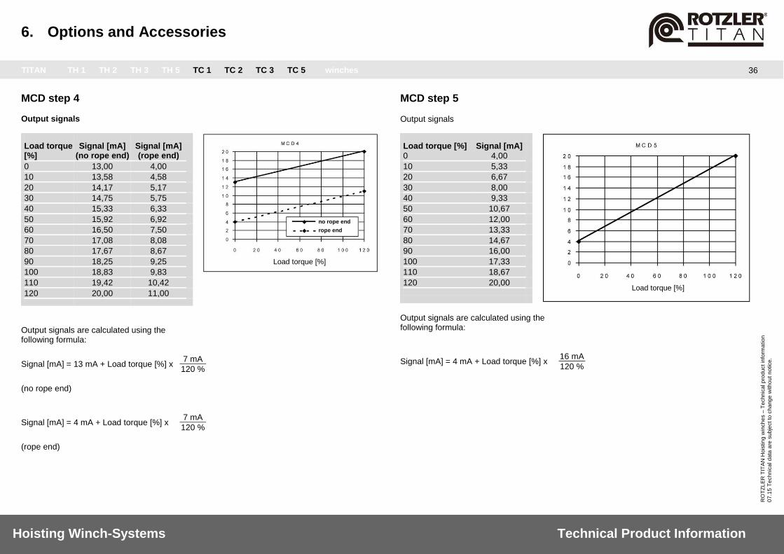
MCD step 4 Output signals
Load torque Signal [mA] Signal [mA] [%] (no rope end) (rope end)
0 13,00 4,00
10 13,58 4,58
20 14,17 5,17
30 14,75 5,75
40 15,33 6,33
50 15,92 6,92
60 16,50 7,50
70 17,08 8,08
80 17,67 8,67
90 18,25 9,25
100 18,83 9,83
110 19,42 10,42
120 20,00 11,00
Output signals are calculated using the following formula:
Signal [mA] = 13 mA + Load torque [%] x 7 mA
120 % (no rope end)
Signal [mA] = 4 mA + Load torque [%] x 7 mA
120 % (rope end)
MCD step 5 Output signals
Load torque [%] Signal [mA] 0 4,00
10 5,33
20 6,67
30 8,00
40 9,33
50 10,67
60 12,00
70 13,33
80 14,67
90 16,00
100 17,33
110 18,67
120 20,00
Output signals are calculated using the following formula:
Signal [mA] = 4 mA + Load torque [%] x 16 mA
120 %
no rope end
rope end
Load torque [%]
Load torque [%]

6. Options and Accessories
TITAN TH 1 TH 2 TH 3 TH 5 TC 1 TC 2 TC 3 TC 5 winches
37
Hoisting Winch-Systems Technical Product Information
RO
TZ
LE
R T
ITA
N H
ois
tin
g w
inch
es –
Te
chn
ica
l p
rod
uct in
form
atio
n
07
.15
Te
ch
nic
al d
ata
are
su
bje
ct
to c
ha
ng
e w
ith
ou
t n
otice.
Electric installation for MCD step 4/5 Fig. 10
Connections sensor functions (output) and voltage supply
MCD-step 4: combined rope end and torque signal (signal 1). Signal 2 without function. MCD-step 5: separate rope end (signal1) and torque (signal 2) signals. To ensure correct winch operation, a suitable electronic control system capable of processing the MCD output signals, must be provided.
ele
ctr
onic
box
core I blue
core II grey
core III black
core IV white
core V red
core VI brown 0V
+8 V…+36 V
+8 V…+36 V
4 ma – 20 mA
ground connection
ground connection
signal 1
signal 2
power supply
MCD-step 4
MCD-step 5
6. Options and Accessories
TITAN TH 1 TH 2 TH 3 TH 5 TC 1 TC 2 TC 3 TC 5 winches
38
Hoisting Winch-Systems Technical Product Information
RO
TZ
LE
R T
ITA
N H
ois
tin
g w
inch
es –
Te
chn
ica
l p
rod
uct in
form
atio
n
07
.15
Te
ch
nic
al d
ata
are
su
bje
ct
to c
ha
ng
e w
ith
ou
t n
otice.
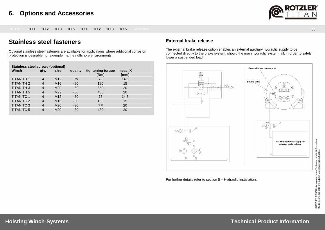
Stainless steel fasteners Optional stainless steel fasteners are available for applications where additional corrosion protection is desirable; for example marine / offshore environments. Stainless steel screws (optional) Winch qty. size quality tightening torque meas. X [Nm] [mm]
TITAN TH 1 4 M12 -80 73 14,5
TITAN TH 2 4 M16 -80 180 15
TITAN TH 3 4 M20 -80 360 20
TITAN TH 5 4 M22 -80 480 20
TITAN TC 1 4 M12 -80 73 14,5
TITAN TC 2 4 M16 -80 180 15
TITAN TC 3 4 M20 -80 360 20
TITAN TC 5 4 M20 -80 480 20
External brake release The external brake release option enables an external auxiliary hydraulic supply to be connected directly to the brake system, should the main hydraulic system fail, in order to safely lower a suspended load.
For further details refer to section 5 – Hydraulic installation.
External brake release port
Shuttle valve
Auxilary hydraulic supply for
external brake release

6. Options and Accessories
TITAN TH 1 TH 2 TH 3 TH 5 TC 1 TC 2 TC 3 TC 5 winches
39
Hoisting Winch-Systems Technical Product Information
RO
TZ
LE
R T
ITA
N H
ois
tin
g w
inch
es –
Te
chn
ica
l p
rod
uct in
form
atio
n
07
.15
Te
ch
nic
al d
ata
are
su
bje
ct
to c
ha
ng
e w
ith
ou
t n
otice.
Counterbalance valve The counterbalance valve option offers an alternative lowering brake function designed to suit specific applications and hydraulic systems. The counterbalance valve option also features a failsafe, spring applied, static disc brake. • Optimizes lowering speed in ‘low flow’ hydraulic systems. • Optimized lowering performance in high pressure mobile hydraulic systems.
Pressure roller The sprung pressure roller is made from stainless steel components including heavy duty springs, and nylon roller. • Enhances rope spooling onto the drum. • Ensures slack rope remains on the drum. • Extends rope life expectancy. • Suitable for marine applications
Grooved drum sleeves Rotzler offers a special hard wearing nylon grooved sleeve system which can be supplied to suit different rope diameters. • Enhances rope spooling onto the drum. • Improves winch operation. • Extends rope life expectancy.

6. Options and Accessories
TITAN TH 1 TH 2 TH 3 TH 5 TC 1 TC 2 TC 3 TC 5 winches
40
Hoisting Winch-Systems Technical Product Information
RO
TZ
LE
R T
ITA
N H
ois
tin
g w
inch
es –
Te
chn
ica
l p
rod
uct in
form
atio
n
07
.15
Te
ch
nic
al d
ata
are
su
bje
ct
to c
ha
ng
e w
ith
ou
t n
otice.
Hook weight system The flexible and modular hook weight system with integrated snatch block system is designed for single- and two-part-line configurations and is part of the ROTZLER System for Loading Cranes. Main features Hook weight: • Increased product flexibility through a modular design. • Improved spooling by offering different hook weight options. • Reliable two-part-line operation using integrated snatch block option, fully compatible to
ROTZLER Top Roller accessories. • Compatible to current standards and the EC Machinery Directive 2006/42/EG. • Increased safety due to captive rope splice protection system. • Maximize hoisting travel in confined working spaces by reducing overall length. • Quick and easy assembly. • Quick and easy to change from single part line to two part line operation. • Compliance to single person lifting regulations.
Main features integrated Snatch block option: • Improved spooling by using optional additional weights. • Improved stability without load. • Anti-2-block function in combination with ROTZLER Top Rollers. • Compatible to current standards and the EC Machinery Directive 2006/42/EG.
Single Part Line
Two Part Line
Standard version Extra weight option Standard version
+ Snatch block
Standard version + Snatch block
+ Extra weight
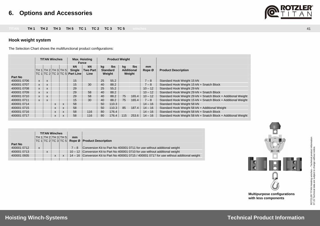
6. Options and Accessories
TITAN TH 1 TH 2 TH 3 TH 5 TC 1 TC 2 TC 3 TC 5 winches
41
Hoisting Winch-Systems Technical Product Information
RO
TZ
LE
R T
ITA
N H
ois
tin
g w
inch
es –
Te
chn
ica
l p
rod
uct in
form
atio
n
07
.15
Te
ch
nic
al d
ata
are
su
bje
ct
to c
ha
ng
e w
ith
ou
t n
otice.
Multipurpose configurations
with less components
Hook weight system The Selection Chart shows the multifunctional product configurations: TITAN Winches Max. Hoisting
Force Product Weight
kN kN kg lbs kg lbs mm TH 1
TC 1 TH 2 TC 2
TH 3 TC 3
TH 5 TC 5
Single Part Line
Two Part Line
Standard Weight
Additional Weight
Rope Ø Product Description
Part No 400001 0706 x x 15 25 55.2 7 – 8 Standard Hook Weight 15 kN
400001 0707 x x 15 30 40 88.2 7 – 8 Standard Hook Weight 15 kN + Snatch Block
400001 0708 x x 29 25 55.2 10 – 12 Standard Hook Weight 29 kN
400001 0709 x x 29 58 40 88.2 10 – 12 Standard Hook Weight 29 kN + Snatch Block
400001 0710 x x 29 58 40 88.2 75 165.4 10 – 12 Standard Hook Weight 29 kN + Snatch Block + Additional Weight
400001 0711 x x 15 30 40 88.2 75 165.4 7 – 8 Standard Hook Weight 15 kN + Snatch Block + Additional Weight
400001 0714 x x 58 50 110.3 14 – 16 Standard Hook Weight 58 kN
400001 0715 x x 58 50 110.3 85 187.4 14 – 16 Standard Hook Weight 58 kN + Additional Weight
400001 0716 x x 58 116 80 176.4 14 – 16 Standard Hook Weight 58 kN + Snatch Block
400001 0717 x x 58 116 80 176.4 115 253.6 14 – 16 Standard Hook Weight 58 kN + Snatch Block + Additional Weight
TITAN Winches
TH 1 TC 1
TH 2 TC 2
TH 3 TC 3
TH 5 TC 5
mm Rope Ø Product Description
Part No 400001 0712 x 7 – 8 Conversion Kit to Part No 400001 0711 for use without additional weight
400001 0713 x 10 – 12 Conversion Kit to Part No 400001 0710 for use without additional weight
400001 0935 x x 14 – 16 Conversion Kit to Part No 400001 0715 / 400001 0717 for use without additional weight
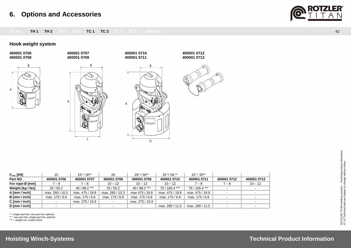
6. Options and Accessories
TITAN TH 1 TH 2 TH 3 TH 5 TC 1 TC 2 TC 3 TC 5 winches
42
Hoisting Winch-Systems Technical Product Information
RO
TZ
LE
R T
ITA
N H
ois
tin
g w
inch
es –
Te
chn
ica
l p
rod
uct in
form
atio
n
07
.15
Te
ch
nic
al d
ata
are
su
bje
ct
to c
ha
ng
e w
ith
ou
t n
otice.
Hook weight system 400001 0706 400001 0707 400001 0710 400001 0712 400001 0708 400001 0709 400001 0711 400001 0713
Fmax [kN] 15 15* / 30** 29 29* / 58** 29 */ 58 ** 15* / 30**
Part NO 400001 0706 400001 0707 400001 0708 400001 0709 400001 0710 400001 0711 400001 0712 400001 0713
For rope-Ø [mm] 7 – 8 7 – 8 10 – 12 10 – 12 10 – 12 7 – 8 7 – 8 10 – 12
Weight [kg / lbs] 25 / 55.2 40 / 88.2 *** 25 / 55.2 40 / 88.2 *** 75 / 165.4 *** 75 / 165.4 *** - -
A [mm / inch] max. 260 / 10.3 max. 475 / 18.8 max. 260 / 10.3 max 475 / 18.8 max. 475 / 18.8 max. 475 / 18.8 - -
B [mm / inch] max. 175 / 6.9 max. 175 / 6.9 max. 175 / 6.9 max. 175 / 6.9 max. 175 / 6.9 max. 175 / 6.9 - -
C [mm / inch] - max. 275 / 10.9 - max. 275 / 10.9 - - - -
D [mm / inch] - - - - max. 290 / 11.5 max. 290 / 11.5 - -
* = single-part line, two-part line optional ** = two-part line, single-part line optional *** = weight incl. snatch block
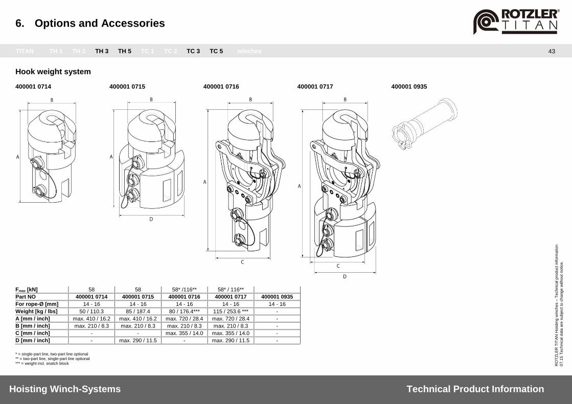
6. Options and Accessories
TITAN TH 1 TH 2 TH 3 TH 5 TC 1 TC 2 TC 3 TC 5 winches
43
Hoisting Winch-Systems Technical Product Information
RO
TZ
LE
R T
ITA
N H
ois
tin
g w
inch
es –
Te
chn
ica
l p
rod
uct in
form
atio
n
07
.15
Te
ch
nic
al d
ata
are
su
bje
ct
to c
ha
ng
e w
ith
ou
t n
otice.
Hook weight system 400001 0714 400001 0715 400001 0716 400001 0717 400001 0935
Fmax [kN] 58 58 58* /116** 58* / 116**
Part NO 400001 0714 400001 0715 400001 0716 400001 0717 400001 0935
For rope-Ø [mm] 14 - 16 14 - 16 14 - 16 14 - 16 14 - 16
Weight [kg / lbs] 50 / 110.3 85 / 187.4 80 / 176.4*** 115 / 253.6 *** -
A [mm / inch] max. 410 / 16.2 max. 410 / 16.2 max. 720 / 28.4 max. 720 / 28.4 -
B [mm / inch] max. 210 / 8.3 max. 210 / 8.3 max. 210 / 8.3 max. 210 / 8.3 -
C [mm / inch] - - max. 355 / 14.0 max. 355 / 14.0 -
D [mm / inch] - max. 290 / 11.5 - max. 290 / 11.5 -
* = single-part line, two-part line optional ** = two-part line, single-part line optional *** = weight incl. snatch block

6. Options and Accessories
TITAN TH 1 TH 2 TH 3 TH 5 TC 1 TC 2 TC 3 TC 5 winches
44
Hoisting Winch-Systems Technical Product Information
RO
TZ
LE
R T
ITA
N H
ois
tin
g w
inch
es –
Te
chn
ica
l p
rod
uct in
form
atio
n
07
.15
Te
ch
nic
al d
ata
are
su
bje
ct
to c
ha
ng
e w
ith
ou
t n
otice.
Top roller
Fmax [kN] 15 29 43 58
Part NO 400000 6808 400000 7707 400000 6798 400000 7676
For rope-Ø [mm] 8 ... 9 10 ... 12 14 ... 16 14 ... 16
Weight [kg / lbs] 10,0 22,0 14,0 31,0 26,0 57,0 32,0 71,0
A [mm / inch] 160 6,3 160 6,3 160 6,3 160 6,3
B [mm / inch] 124 4,9 124 4,9 124 4,9 124 4,9
C [mm / inch] 82 3,2 82 3,2 82 3,2 82 3,2
D [mm / inch] 25 1,0 25 1,0 25 1,0 25 1,0
E [mm / inch] 78 3,1 78 3,1 78 3,1 78 3,1
F [mm / inch] 135 5,3 180 7,1 240 9,4 240 9,4
G [mm / inch] 20 0,8 22 0,9 28 1,1 30 1,2
H [mm / inch] 21,5 0,84 23,5 0,92 23 0,90 29 1,14
I [mm / inch] 125 4,9 125 4,9 135 5,3 135 5,3
J [mm / inch] 75 2,9 75 2,9 82,5 3,24 82,5 3,24
K [mm / inch] 20 0,8 20 0,8 25 1,0 25 1,0
L [mm / inch] 159 ... 165 6,2 - 6,5 210 ... 216 8,2 - 8,5 282 ... 288 11,1 - 11,3 282 ... 288 11,1 - 11,3
M [mm / inch] 20 0,8 25 1,0 30 1,2 30 1,2
N [mm / inch] 275 10,8 355 13,9 445 17,5 445 17,5
O [mm / inch] 235 9,2 310 12,0 395 15,6 395 15,6
Maximum load in single line pull: 43 kN Maximum load dual line pull: 86 kN
Customer Attachment

6. Options and Accessories
TITAN TH 1 TH 2 TH 3 TH 5 TC 1 TC 2 TC 3 TC 5 winches
45
Hoisting Winch-Systems Technical Product Information
RO
TZ
LE
R T
ITA
N H
ois
tin
g w
inch
es –
Te
chn
ica
l p
rod
uct in
form
atio
n
07
.15
Te
ch
nic
al d
ata
are
su
bje
ct
to c
ha
ng
e w
ith
ou
t n
otice.
Swivel hook
Safe working load F [KN] 10 20 32 50 80 125
Part NO 011875 0000 011878 0000 011879 0000 011880 0000 011954 0000 012244 0000
Weight [kg] 0,6 1,3 1,4 3 2,5 5,5 5,4 12 7 15,4 9,6 21,1
A [mm / inch] 26 1,03 36 1,5 39 1,61 61 2,5 60 2,4 71 2,8
B [mm / inch] 21 0,84 33 1,3 30 1,2 58 2,3 54 2,2 58 2,3
C [mm / inch] 10 0,4 17 0,7 18 0,78 23 1 20 0,9 23 1
D [mm / inch] 26 1,03 32 1,3 42 1,7 46 2 51 2,01 55 2,2
E [mm / inch] 166 6,6 229 9,02 261 10,3 357 14,1 400 15,85 480 19
F [mm / inch] 22 0,9 28 1,11 33 1,32 45 1,9 74 3 89 3,6
G [mm / inch] 21 0,86 30 1,2 31 1,25 42 1,7 42 1,7 42 1,75
H [mm / inch] 130 5,2 180 7,1 201 8 288 11,4 321 12,8 355 14
Ropes
Rope-Ø* [mm] 7 8 10 12 12° 14 14° 16
Part NO 250850 3037 250850 3068
250851 3038 250851 3050
400000 0046 400000 0047 400000 0048
250853 3046 250853 3090
40000 13819 40000 13820 40000 13821 40000 13822
250854 3042 400000 0768 250854 3084
400000 2914 400000 4268 400000 2346
250855 3056 250855 3093
Rope length** [m] 37 / 68 38 / 50 49 / 60 / 69 46 / 90 70 / 94 / 120 / 130 42 / 65 / 84 50 / 65 / 90 56 / 93
Weight [kg/m] 0,2 0,26 0,47 0,61 0,96 0,88 0,94 1,15
Class of rope strength 1960 1960 2160 1960 2160 1960 2260 1960
Min. breaking strength*** [kN]
39 53,3 95,4 119 146 159 196 211
Stranding factor 0,77 0,79 0,82 0,75 0,75 0,80 0,80 0,75
Ferrule swaging EN 13411-3 EN 13411-3 EN 13411-3 EN 13411-3 EN 13411-3 EN 13411-3 EN 13411-3 EN 13411-3
Strand surface 0,77 Zinc Zinc Zinc Zinc Zinc Zinc Zinc Zinc
A [mm] +0,15 / -1,0 20 20 25 30 35 35 35 40
B max. [mm] 48 50 72 62 80 84 84 95
C [mm] 15 15 17,5 20 23,5 23,5 23,5 26
D max. [mm] 3,5 4 5 6 6 7 7 8
Rope type: Lang‘s lay right, rotation-resistant * permissibale nominal diameter; usual Ø-tolerance: +0 ... + 5 %; usual Ø-tolerance grooved drum: +2 ... +4 % ** rope length must be chosen, so that the drum free flange is >= 0 *** usual: 3,55 x nominal lifting force (in gear class M3). GL-certification: 5 x nominal lifting force. ° increased min. breaking strength
7. Service
TITAN TH 1 TH 2 TH 3 TH 5 TC 1 TC 2 TC 3 TC 5 winches
46
Hoisting Winch-Systems Technical Product Information
RO
TZ
LE
R T
ITA
N H
ois
tin
g w
inch
es –
Te
chn
ica
l p
rod
uct in
form
atio
n
07
.15
Te
ch
nic
al d
ata
are
su
bje
ct
to c
ha
ng
e w
ith
ou
t n
otice.
ROTZLER – your expert for winch systems Rotzler provides all you need for successful hoisting applications: winches, accessories, electronics, customized development and winch systems related to praxis. Our international expert team offers you competent service and consulting on your specific demands. Please call us or send us an e-mail for detailed information about Rotzler’s products and services: ROTZLER Deutschland GmbH + Co. KG, Germany
Customer Support Phone +49 (0)7627 701-133 Fax +49 (0)7627 701-198 [email protected]
ROTZLER Canada Inc., Canada
Customer Service Phone +1 604 940-7134 Fax +1 604 940-7135 [email protected]
ROTZLER
Winches
Accessories
Service Systems
Hoisting Winch-Systems Technical Product Information
RO
TZ
LE
R T
ITA
N H
ois
tin
g w
inch
es –
Te
chn
ica
l p
rod
uct in
form
atio
n
07
.15
Te
ch
nic
al d
ata
are
su
bje
ct
to c
ha
ng
e w
ith
ou
t n
otice.
ROTZLER Deutschland GmbH + Co. KG
Winches, Capstans and Winch systems
Robert-Bosch-Strasse 4
79585 Steinen
Germany
Phone +49(0)7627 701-0
Fax +49(0)7627 701-166
ROTZLER Canada Inc.
Unit 122, 7350
72nd Street
Delta, B.C. V4G 1H9
Canada
Phone +1 604 940-7134
Fax +1 604 940-7135
ROTZLER Korea Ltd.
1-110 Changwon Knowledge Industrial Center,
316, Ungnam-ro, Seongsan-gu, Changwon,
Gyeongnam, 642-290
Korea
Phone +82 55 282 5067
Fax +82 55 262 5068
ROTZLER India Pvt. Ltd.
S 806, Manipal Center,
No. 47, Dickenson Road
560042 Bangalore
India
Phone +91 80 4096 36 42
Hoisting Winch-Systems Technical Product Information
RO
TZ
LE
R T
ITA
N H
ois
tin
g w
inch
es –
Te
chn
ica
l p
rod
uct in
form
atio
n
07
.15
Te
ch
nic
al d
ata
are
su
bje
ct
to c
ha
ng
e w
ith
ou
t n
otice.