commercial gas water heaters oi operation flow chart 24 lighting & operation label 25...
TRANSCRIPT

COMMERCIAL GAS WATER HEATERSInstruction Manual
PRINTED 0814 194186-003
PLACE THESE INSTRUCTIONS ADJACENT TO HEATER AND NOTIFY OWNER TO KEEP FOR FUTURE REFERENCE.
MODELS BTP 139(A) Thru 370(A)SERIES 104/105
INSTALLATION - OPERATION - SERVICE - MAINTENANCE - LIMITED WARRANTY
Read and understand this instructionmanual and the safety messagesherein before installing, operating orservicing this water heater.
Failure to follow these instructions andsafety messages could result in deathor serious injury.
This manual must remain with thewater heater.
500 Tennessee Waltz ParkwayAshland City, TN 37015
Low Lead Content
Thank y r yin this ener y e ient water heater We a re iate y r n den e in r r d ts
WARNING: If the information in theseinstructions is not followed exactly, a fireor explosion may result causing propertydamage, personal injury or death.
Do not store or use gasoline or otherflammable vapors and liquids in thevicinity of this or any other appliance.
WHAT TO DO IF YOU SMELL GAS:Do not try to light any appliance.Do not touch any electrical switch; donot use any phone in your building.Immediately call your gas supplierfrom a neighbor’s phone. Follow thegas supplier’s instructions.
If you cannot reach your gas supplier,call the fire department.
Installation and service must beperformed by a qualified installer,service agency or the gas supplier.
2
Air r ther Ind r a es 18
ent C nne ti n 19
WATER HEATER INSTALLATION 19-22
Water Line C nne ti ns 19
T P al e Dis har e Pi e 19
Installation Diagrams - Top Inlet/Outlet Usage 20
Burner Installation 20
Heater Wiring 21
Gas Piping 22
Gas Line Leak Testing 22
Purging 22
STARTUP AND OPERATION 23
Prior to Start Up 23
SEQUENCE OF OPERATION 23-27
Se uen e o Operation Flow Chart 24
Lighting & Operation Label 25
Adjustments 26
Che king enting 26
Che king the Input 26
Setting Burner Operation 27
MAINTENANCE 28-32
enting System and Barometri Dra t Control 28
General 28
Remote Storage Tank Temperature Control 28
Temperature-Pressure Relief Valve Test 28
Anode Rod Inspe tion 29
Draining and Flushing 29
Re ommended Pro edure for Periodi Removal or Lime Deposits from the Tank Type Commer ial Water Heaters 29
DeLiming Solvents 30
Tank Cleanout Pro edure 30
Deliming Using Flo-Jug Method 30-31
Power Burner 31-32
Gas Control Valve 32
SERVICE 32
Ele tri al Servi ing 32
TROUBLESHOOTING CHECKLIST 33
FOR YOUR INFORMATION 34
Start up Conditions 34
Operational Conditions 34
WATER PIPING DIAGRAMS 35-49
MANIFOLD KITS 50
REPLACEMENT PARTS LIST 51-52
NOTES 53-54
WARRANTY 55
TABLE OF CONTENTS
SAFE INSTALLATION, USE AND SERVICE 3
APPROVALS 3
GENERAL SAFETY INFORMATION 4-5
Pre autions 5
Grounding Instru tions 5
Hydrogen Gas Flammable 5
INTRODUCTION 6
Abbreviations Used 6
Quali ations 6
Start Up Requirements 6
Preparing for the Installation 6
FEATURES AND COMPONENTS 7
High Limit Swit h 7
Ele troni Ignition Control 7
Barometri Draft Control 7
Combustion Chamber Observation Port 7
Un rating 7
INSTALLATION CONSIDERATIONS 8-12
Rough In Dimensions 8
Lo ating The Water Heater 10
Clearan es 10
Insulation Blanket 11
Hard Water 11
Cir ulation Pumps 11-12
High Altitude Installations 12
INSTALLATION REQUIREMENTS 13-16
Gas Supply Systems 13
Supply Gas Regulator 13
Power Supply 13
Water Temperature Control and Mixing Valves 13
Dishwashing Ma hines 14
Closed Water Systems 14
Thermal Expansion 14
Temperature-Pressure Relief Valve 14-15
Contaminated Air 15
Air Requirements 15
Un on ned Spa e 16
Con ned Spa e 16
VENTING INSTALLATION 16-19
Venting 16
Barometri Draft Control Assembly 16
Fresh Air Opening for Con ned Spa es 17
Outdoor Air Through Two Openings 17
Outdoor Air Through One Opening 17
Outdoor Air Through Two Horizontal Du ts 17
Outdoor Air Through Two Verti al Du ts 18

3
SAFE INSTALLATION, USE AND SERVICE
The proper installation, use and servi ing of this water heater is extremely important to your safety and the safety of othersMany safety-related messages and instru tions have been provided in this manual and on your own water heater to warn you and others of a potential injury hazard Read and obey all safety messages and instru tions throughout this manual It is very important that the meaning of ea h safety message is understood by you and others who install, use, or servi e this water heater
All safety messages will generally tell you about the type of hazard, what an happen if you do not follow the safety message, and how to avoid the risk of injuryThe California Safe Drinking Water and Toxi Enfor ement A t requires the Governor of California to publish a list of substan es known to the State of California to ause an er, birth defe ts, or other reprodu tive harm, and requires businesses to warn of potential exposure to su h substan esWARNING: This produ t ontains a hemi al known to the State of California to ause an er, birth defe ts, or other reprodu tive harm This applian e an ause low level exposure to some of the substan es listed in the A t
DANGER
WARNING
CAUTION
CAUTION
DANGER indicates an imminentlyhazardous situation which, if not avoided,will result in injury or death.
This is the safety alert symbol. It is used to alert you topotential personal injury hazards. Obey all safetymessages that follow this symbol to avoid possibleinjury or death.
WARNING indicates a potentially hazardoussituation which, if not avoided, could resultin injury or death.
CAUTION indicates a potentially hazardoussituation which, if not avoided, could result inminor or moderate injury.
CAUTION used without the safety alertsymbol indicates a potentially hazardoussituation which, if not avoided, could result inproperty damage.
APPROVALS
Note: ASME onstru tion is optional on the water heaters overed in this manual
Low Lead Content

4
GENERAL SAFETY INFORMATION
Fire or Explosion Hazard
Read instruction manual beforeinstalling, using or servicing
water heater.
Avoid all ignition sources if you smell gas.
Do not store or use gasoline or other flammable vapors andliquids in the vicinity of this or any other appliance.
Use only the gas shown on the water heater rating label.
Keep ignition sources away from faucets after extendedperiods of non-use.
Maintain required clearances to combustibles.
Do not expose water heater controls to excessive gaspressure.
Property Damage Hazard
All water heaters eventually leak.
Do not install without adequate drainage.
CAUTION
Fire and Explosion Hazard
Leak test before placing thewater heater in operation.Disconnect gas piping and maingas shutoff valve before leaktesting.Install sediment trap inaccordance with NFPA 54.
Use joint compound or Teflon tapecompatible with propane gas.
Turn off power to the water heaterbefore performing any service.
Electrical Shock Hazard
Label all wires prior to disconnectingwhen performing service. Wiring errorscan cause improper and dangerousoperation.
Verify proper operation after servicing.
Failure to follow these instructions canresult in personal injury or death.
Fire Hazard For continued protection against
risk of fire:Do not install water heater oncarpeted floor.Do not operate water heater ifany part has been exposed to flooding or water damage.
Fire and Explosion Hazard
Turn off gas lines during installation.Contact a qualified installer or servicetechnician for installation and service.
Excessive gas pressure to gas valve cancause serious injury or death.
Do not use water heater with any gasother than the gas shown on the ratinglabel.
Jumping out control circuits or components canresult in property damage, personal injury or death.
Service should only be performed by a qualified servicetechnician using proper test equipment.Altering the water heater controls and/or wiring in any waycould result in permanent damage to the controls or waterheater and is not covered under the limited warranty.
Any bypass or alteration of the waterheater controls and/or wiring will resultin voiding the water heater warranty.
Altering the water heater controls and/or wiring in any waycould result in altering the ignition sequence allowing gas toflow to the main burner before the hot surface igniter is atignition temperature causing delayed ignition which cancause a fire or explosion.

5
PRECAUTIONS
DO NOT USE THIS WATER HEATER IF ANY PART HAS BEEN E POSED TO FLOODING OR WATER DAMAGE Immediately all a qualified servi e te hni ian to inspe t the water heater and to make a determination on what steps should be taken nextIf the unit is exposed to the following, do not operate heater until all orre tive steps have been made by a qualified servi e te hni ian
1 External re2 Damage3 Firing without water
GROUNDING INSTRUCTIONS
This water heater must be grounded in a ordan e with the National Ele tri al Code and/or lo al odes These must be followed in all ases
This water heater must be onne ted to a grounded, permanent wiring system or an equipment grounding ondu tor must be run with the ir uit ondu tors and onne ted to the equipment grounding terminal or lead on the water heater, see Figure 19
HYDROGEN GAS FLAMMABLE
Explosion Hazard
Flammable hydrogen gasesmay be present.
Keep all ignition sources awayfrom faucet when turning onhot water.
Hydrogen gas an be produ ed in a hot water system served by this water heater that has not been used for a long period of time generally two weeks or more Hydrogen gas is extremely ammable To redu e the risk of injury under these onditions,
it is re ommended that a hot water fau et served by this water heater be opened for several minutes before using any ele tri al applian e onne ted to the hot water system If hydrogen is present there will probably be an unusual sound su h as air es aping through the pipe as the water begins to ow THERE SHOULD BE NO SMOKING OR OPEN FLAME NEAR THE FAUCET AT THE TIME IT IS OPEN
GENERAL SAFETY INFORMATION
Verify the power to the water heater is turned off before performing any service procedures.
Read and understand this instructionmanual and the safety messagesherein before installing, operating orservicing this water heater.
Failure to follow these instructions andsafety messages could result in deathor serious injury.
This manual must remain with thewater heater.
Water temperature over 125°F (52°C)can cause severe burns instantlyresulting in severe injury or death.
Children, the elderly and thephysically or mentally disabled are athighest risk for scald injury.
Feel water before bathing orshowering.
Temperature limiting devices such asmixing valves must be installedwhen required by codes and toensure safe temperatures at fixtures.
Explosion Hazard
Overheated water can causewater tank explosion.
Properly sized temperature andpressure relief valve must beinstalled in the opening provided.
GENERAL SAFETY INFORMATION
Improper installation, use and service may resultin property damage.
Do not operate water heater if any part has been exposed to flooding or water damage.Inspect anode rods regularly, replace if damaged.Install in location with drainage.Fill tank with water before operation.Properly sized thermal expansion tanks are required on all closed water systems.
Refer to this manual for installation and service.
CAUTION

6
INTRODUCTIONThank You for pur hasing this water heater Properly installed and maintained, it should give you years of trouble free servi e
ABBREVIATIONS USED
Abbreviations found in this Instru tion Manual in lude ANSI - Ameri an National Standards Institute ASME - Ameri an So iety of Me hani al Engineers AHRI - Air-Conditioning, Heating and Refrigeration Institute NEC - National Ele tri al Code NFPA - National Fire Prote tion Asso iation UL - Underwriters Laboratory CSA - Canadian Standards Asso iation
QUALIFICATIONS
QUALIFIED INSTALLER OR SERVICE AGENCYInstallation and servi e of this water heater requires ability equivalent to that of a Quali ed Agen y as de ned by ANSI below in the eld involved Installation skills su h as plumbing, air supply, venting, gas supply and ele tri al supply are required in addition to ele tri al testing skills when performing servi e
ANSI Z223.1 2006 Sec. 3.3.83: Quali ed Agen y - Any individual, rm, orporation or ompany that either in person or through a representative is engaged in and is responsible for (a) the installation, testing or repla ement of gas piping or (b) the onne tion, installation, testing, repair or servi ing of applian es
and equipment that is experien ed in su h work that is familiar with all pre autions required and that has omplied with all the requirements of the authority having jurisdi tion
If you are not quali ed (as de ned by ANSI above) and li ensed or erti ed as required by the authority having jurisdi tion to perform a given task do not attempt to perform any of the pro edures des ribed in this manual If you do not understand the instru tions given in this manual do not attempt to perform any pro edures outlined in this manual
START UP REQUIREMENTS
This produ t requires a formal Start-Up by an authorized servi e/
start-up provider that has been approved by the manufa turer for this spe i produ t Call 1-800-527-1953 to lo ate the nearest authorized start-up provider and arrange a fa tory start-up Please provide as mu h noti e as possible, preferably 2 weeks Please have the model and serial number ready when you all
This start-up is required to a tivate the warranty and ensure safe, ef ient operation
Warranty on this produ t is limited and ould be void in the event the unit is not installed per the instru tions in this manual and/or not started up by an authorized fa tory trained servi e/start-up provider
PREPARING FOR THE INSTALLATION
1 Read the General Safety se tion, page 4-5 of this manual first and then the entire manual arefully If you don t follow the safety rules, the water heater will not operate properly It ould ause DEATH, SERIOUS BODILY INJURY AND/OR PROPERTY DAMAGE
This manual ontains instru tions for the installation, operation, and maintenan e of the gas- red water heater It also ontains warnings throughout the manual that you must read and be aware of All warnings and all instru tions are essential to the proper operation of the water heater and your safety Sin e we annot put everything on the rst few pages, READ THE ENTIRE
MANUAL BEFORE ATTEMPTING TO INSTALL OR OPERATE THE WATER HEATER
2 The installation must onform with these instru tions and the lo al ode authority having jurisdi tion In the absen e of lo al odes, the installation must omply with the urrent editions
of the National Fuel Gas Code, ANSI 223 1/NFPA 54 or CAN/CSA-B149 1 the Natural Gas and Propane Installation Code All do uments are available from the Canadian Standards Asso iation, 8501 East Pleasant Valley Road, Cleveland, OH 44131 NFPA do uments are also available from the National Fire Prote tion Asso iation, 1 Batterymar h Park, Quin y, MA 02269
3 If after reading this manual you have any questions or do not understand any portion of the instru tions, all the lo al gas utility or the manufa turer whose name appears on the rating plate
4 Carefully plan the pla e where you are going to put the water heater Corre t ombustion, vent a tion, and vent pipe installation are very important in preventing death from possible arbon monoxide poisoning and res
Examine the lo ation to ensure the water heater omplies with the Lo ating the New Water Heater se tion in this manual
5 For California installation this water heater must be bra ed, an hored, or strapped to avoid falling or moving during an earthquake See instru tions for orre t installation pro edures Instru tions may be obtained from California Offi e of the State Ar hite t, 400 P Street, Sa ramento, CA 95814
6 Massa husetts Code requires this water heater to be installed in a ordan e with Massa husetts 248-CMR 2 00 State Plumbing Code and 248-CMR 5 00

7
HIGH LIMIT SWITCH
The dual bulb ontroller ( g 1) ontains the high limit (energy utoff) sensor The high limit swit h interrupts main burner gas ow should the water temperature rea h 205 F (96 C)In the event of high limit swit h operation, the applian e annot be restarted unless the water temperature is redu ed by at least 20 F (11 C) and the high limit reset button on front of limit ontrol ( g 1) is depressedContinued manual resetting of high limit ontrol, pre eded by higher than usual water temperature is eviden e of high limit swit h operation The following is a possible reason for high limit swit h operation A malfun tion in the thermostati ontrols would allow the gas
ontrol valve to remain open ausing water temperature to ex eed the thermostat setting The water temperature would ontinue to rise until high limit swit h operation
Conta t your dealer or servi e agent if ontinued high limit swit h operation o urs
DIGITAL THERMOSTAT
FIGURE 1.
ELECTRONIC IGNITION CONTROL
Ea h heater is equipped with a Honeywell ignition module TheDire t Spark Ignition Control Module ontrols the ignition sequen e and gas ontrol operation of the water heater
IGNITION MODULEFIGURE 2.
BAROMETRIC DRAFT CONTROL
The heater is equipped with a double a ting barometri draft ontrol This ontrol assembly is fa tory adjusted to automati ally
regulate the himney draft imposed on the unit
BAROMETRIC DRAFT CONTROLFIGURE 3.
COMBUSTION CHAMBER OBSERVATION PORT
The ombustion hamber observation a ess panel is lo ated above and to the left of the burner A plug lo ated under the panel, see fig 5, is inserted into the ombustion hamber wall This plug should not be removed ex ept, in rare ases, when the ombustion hamber requires leaning or repla ement
FIGURE 4.
UNCRATING
Un rate the heater by removing the outside mat and top lo ator The shipping pallet must be removed from the unit It may be possible to simply unbolt the base from the pallet and, with the help of 2 or more persons, work the unit off the pallet Some units will be too heavy and will require the use of ja ks or lifting equipment to safely remove the pallet and move the unit into position Be areful when moving this heater It will tip over easilyThe heater is shipped with a burner and draft ontrol The burner and draft ontrol are shipped in separate artons They should be installed as re eived without any alterationsDis ard the shipping rate and pa kaging artons in an appropriate manner
FEATURES AND COMPONENTS

8
ROUGH IN DIMENSIONS
INSTALLATION CONSIDERATIONS
FIGURE 5.
TABLE 1 . MODELS BTP-139(A) THROUGH BTP-370(A)
MODELS A B C D E G H J GASAPPROX. SHIP. WT.
(LBS.) IN OUTASME STD.
BTP-139/A 74 3/4" 65" 26 3/4" 6" 21 3/8" 27 3/4" 38" 85 1/4" 1/2 658 556 1 1/2" 1 1/2"BTP-199/A 74 3/4" 65" 26 3/4" 6" 21 3/8" 27 3/4" 38" 85 1/4" 1/2 635 545 1 1/2" 1 1/2"BTP-270/A 74 3/4" 65" 26 3/4" 8" 21 3/8" 27 3/4" 38" 85 1/4" 3/4 632 547 1 1/2" 1 1/2"BTP-370/A 74 3/4" 65" 26 3/4" 8" 21 3/8" 27 3/4" 38" 85 1/4" 3/4 731 634 1 1/2" 1 1/2"

9
TABLE 2. HEATER PERFORMANCE DATA BTP MODELS
MODELSSTORAGE CAPACITY
U.S. GALLONSIMPUT RATING BTU/HR. RECOVERY RATE
GPH@100°F RISERECOVERY RATE GPH@140°F RISE
MAXIMUM AMPERES
120V, 60Hz, 10
BTP-139/A 81 140,000 136 97 5
BTP-199/A 81 199,000 193 138 5
BTP-270/A 81 270,000 262 187 5
BTP-370/A 81 370,000 359 256 5
Models with letter A following the model number have the optional ASME tank onstru tionThe BTP-370 is available in natural gas only
TABLE 3. GAS AND ELECTRICAL CHARACTERISTICS
Model Type of Gas
Gas Supply Pressure
Gas Manifold Pressure Volts/Hz AmperesMinimum Maximum
All Models Natural 4 5" W C (1 12 kPa) 14" W C (3 48 kPa) 3 5" W C (0 87 kPa) 120/60 <5
All Models * Propane 4 5" W C (1 12 kPa) 14" W C (3 48kPa) 3 5" W C (0 87 kPa) 120/60 <5
* Model BTP-370(A) is not available in Propane
INSTALLATION CONSIDERATIONS
10
The heater must not be lo ated in an area where it will be subje t to freezing
Lo ate it near a oor drain The heater should be lo ated in an area where leakage from heater or onne tions will not result in damage to adja ent area or to lower oors of the stru ture
When su h lo ations annot be avoided, a suitable metal drain pan should be installed under heater Su h pans should be fabri ated with sides at least 2 deep, with length and width at least 2 greater than diameter of heater and must be piped to an adequate drain Pan must not restri t ombustion air ow
CLEARANCES
These heaters are approved for installation on non- ombustible flooring in an al ove when the minimum learan e from ombustion or non- ombustible onstru tion are followed as
indi ated in Figure 7 and Table 5
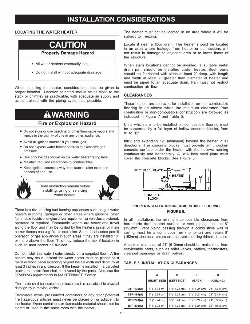
Units whi h are to be installed on ombustible ooring must be supported by a full layer of hollow on rete blo ks, from 8" to 12"
thi k and extending 12" (minimum) beyond the heater in all dire tions The on rete blo ks must provide an unbroken on rete surfa e under the heater with the hollows running ontinuously and horizontally A 3/16 in h steel plate must over the on rete blo ks See Figure 5
PROPER INSTALLATION ON COMBUSTIBLE FLOORINGFIGURE 6.
In all installations the minimum ombustible learan es from barometri draft ontrol surfa e or vent piping shall be 6 (152mm) Vent piping passing through a ombustible wall or eiling must be a ontinuous run (no joints) and retain 6
(152mm) learan e unless an approved redu ing thimble is used
A servi e learan e of 24 (610mm) should be maintained from servi eable parts, su h as relief valves, baf es, thermostats, leanout openings or drain valves
TABLE 5. INSTALLATION CLEARANCES
A
(RIGHT SIDE)
B
(LEFTSIDE)
C
(BACK)
D
(CEILING)
BTP-139(A) 6" (15 24 m) 6" (15 24 m) 6" (15 24 m) 21" (53 34 m)
BTP-199(A) 6" (15 24 m) 6" (15 24 m) 6" (15 24 m) 21" (53 34 m)
BTP-270(A) 6" (15 24 m) 6" (15 24 m) 6" (15 24 m) 21" (53 34 m)
BTP-370(A) 6" (15 24 m) 6" (15 24 m) 6" (15 24 m) 24" (60 96 m)
LOCATING THE WATER HEATER
Property Damage Hazard
All water heaters eventually leak.
Do not install without adequate drainage.
CAUTION
When installing the heater, onsideration must be given to proper lo ation Lo ation sele ted should be as lose to the sta k or himney as pra ti able, with adequate air supply and as entralized with the piping system as possible
Fire or Explosion Hazard
Read instruction manual beforeinstalling, using or servicing
water heater.
Avoid all ignition sources if you smell gas.
Do not store or use gasoline or other flammable vapors andliquids in the vicinity of this or any other appliance.
Use only the gas shown on the water heater rating label.
Keep ignition sources away from faucets after extendedperiods of non-use.
Maintain required clearances to combustibles.
Do not expose water heater controls to excessive gaspressure.
There is a risk in using fuel burning applian es su h as gas water heaters in rooms, garages or other areas where gasoline, other ammable liquids or engine driven equipment or vehi les are stored,
operated or repaired Flammable vapors are heavy and travel along the oor and may be ignited by the heater s igniter or main burner ames ausing re or explosion Some lo al odes permit operation of gas applian es in su h areas if they are installed 18 or more above the oor This may redu e the risk if lo ation in su h an area annot be avoided
Do not install this water heater dire tly on a arpeted oor A re hazard may result Instead the water heater must be pla ed on a metal or wood panel extending beyond the full width and depth by at least 3 in hes in any dire tion If the heater is installed in a arpeted al ove, the entire oor shall be overed by the panel Also, see the DRAINING requirements in MAINTENANCE Se tion
The heater shall be lo ated or prote ted so it is not subje t to physi al damage by a moving vehi le
Flammable items, pressurized ontainers or any other potential re hazardous arti les must never be pla ed on or adja ent to
the heater Open ontainers or ammable material should not be stored or used in the same room with the heater
INSTALLATION CONSIDERATIONS

11
is to redu e the standby heat loss en ountered with storage tank heaters The water heaters overed by this manual meet or ex eed the Energy Poli y A t standards with respe t to insulation and standby heat loss requirements, making an insulation blanket unne essaryShould you hoose to apply an insulation blanket to this heater, you should follow these instru tions See the Features and Components se tion of this manual for identifi ation of omponents mentioned below Failure to follow these instru tions an restri t the air flow required for proper ombustion, potentially resulting in fire, asphyxiation, serious personal injury or death
DO NOT apply insulation to the top of the water heater, as this will interfere with safe operation of the draft ontrol
DO NOT over the gas ontrol valve, thermostat or the Temperature-Pressure Relief Valve
DO NOT allow insulation to ome within 2 (5 m) of the burners, to prevent blo kage of ombustion air ow to the burners
DO NOT over the instru tion manual Keep it on the side of the water heater or nearby for future referen e
DO obtain new warning and instru tion labels from the manufa turer for pla ement on the blanket dire tly over the existing labels
DO inspe t the insulation blanket frequently to make ertain it does not sag, thereby obstru ting ombustion air ow
HARD WATER
Where hard water onditions exist, water softening or the threshold type of water treatment is re ommended This will prote t the dishwashers, offee urns, water heaters, water piping and other equipmentSee the Maintenan e Se tion in this manual for sediment and lime s ale removal pro edures
CIRCULATION PUMPS A ir ulating pump is used when a system requires a ir ulating loop or there is a storage tank used in onjun tion with the water heater See Water Piping Diagrams in this manual for installation lo ation of ir ulating pumpsSee the Cir ulation Pump Wiring Diagrams in this manual for ele tri al hookup information Install in a ordan e with the urrent edition of the National Ele tri al Code, NFPA 70 or the
Canadian Ele tri al Code, CSA C22 1All-bronze ir ulating pumps are re ommended for used with ommer ial water heaters
Some ir ulating pumps are manufa tured with sealed bearings and do not require further lubri ation Some ir ulating pumps must be periodi ally oiled Refer to the pump manufa turer s instru tions for lubri ation requirements
FIGURE 7.
INSULATION BLANKET
Do not obstruct water heater air intakewith insulating blanket.Gas and carbon monoxide detectorsare available.Install water heater in accordance withthe instruction manual.
Breathing carbon monoxide can cause brain damage ordeath. Always read and understand instruction manual.
Breathing Hazard - Carbon Monoxide Gas
Insulation blankets are available to the general publi for external use on gas water heaters but are not ne essary with these produ ts The purpose of an insulation blanket

12
Breathing Hazard - Carbon Monoxide Gas
Breathing carbon monoxide can cause brain damage ordeath. Always read and understand instruction manual.
Under no circumstances shouldthe input exceed the rate shownon the water heater’s rating label.
Overfiring could result in damage tothe water heater and sooting.
Gas and carbon monoxide detectorsare available.
Installations above 2000 feet (610 meters) require repla ement of burner orifi es in a ordan e with urrent edition of the National Fuel Gas Code (ANSI Z223 1) For Canadian installations onsult Canadian Installations Code CAN/CSA B149 1 Failure to repla e orifi es will result in improper and ineffi ient operation of the water heater resulting in the produ tion of in reased levels of arbon monoxide gas in ex ess of safe limits whi h ould result in serious personal injury or death
You should onta t your gas supplier for any spe ifi hanges whi h may be required in your area
As the elevation above sea level is in reased, there is less oxygen per ubi foot of air Therefore, the heater input rate should be redu ed at high altitudes for satisfa tory operation with the redu ed oxygen supply Failure to make this redu tion would result in an over firing of the heater ausing sooting, poor ombustion and/or unsatisfa tory heater performan e
Ratings spe i ed by manufa turers for most applian es apply for elevations up to 2000 feet (610m) For elevations above 2000 feet (610), ratings must be redu ed at the rate of 4 for ea h 1000 feet (305m) above sea level For example, if a heater is rated at 78,000 Btuh (22 9 Kwh) at sea level, to rate the heater at 4000 feet (1219m), you subtra t 4 (on e for ea h thousand feet) x 04 (4 input redu tion) x 78,000 (original rating) from the original rating
Therefore, to al ulate the input rating at 4,000 feet (1219m) 4 x 04 x 78,000 12,480 Btuh (3 7 Kwh), 78,000 (22 9 Kwh) - 12,480 (3 7 Kwh) 65,520 Btuh (19 2 Kwh) At 6000 feet (1829m) the orre t input rating should be 59,280 Btuh (17 4 Kwh)
CIRCULATING PUMP WIRING DIAGRAMSTORAGE TANK OR BUILDING RECIRCULATION
FIELD SUPPLIED TEMPERATURE CONTROLINSTALLED IN THE STORAGE TANKOR CIRCULATING LOOP RETURN LINE
CIRCPUMP
MOTOR
L1 HOT
L2 NEUTRAL
120 VACPOWER
NOTE: USE SEPARATE 120 VAC POWERSUPPLY FOR PUMP CIRCUIT. DO NOTSHARE POWER WITH WATER HEATER AS THISMAY CAUSE ELECTRICAL LINE NOISE ANDLEAD TO ERRATIC CONTROL SYSTEMOPERATION.
FIGURE 8.
CIRCULATING PUMP WIRING DIAGRAMDISHWASHER LOOP WITH TOGGLE SWITCH
FIELD SUPPLIED TEMPERATURECONTROL INSTALLED IN THECIRCULATING LOOP RETURN LINE
DISHWASHERTOGGLESWITCH
CIRCPUMP
MOTOR
L1 HOT
L2 NEUTRAL
120 VACPOWER
NOTE: USE SEPARATE 120 VAC POWERSUPPLY FOR PUMP CIRCUIT. DO NOT SHARE POWER WITH WATER HEATER AS THIS MAY CAUSE ELECTRICAL LINE NOISE AND LEAD TO ERRATIC CONTROL SYSTEM OPERATION.
FIGURE 9.
HIGH ALTITUDE INSTALLATIONS
Fire and Explosion Hazard
Gas and carbon monoxide detectors areavailable.
Overfiring could result in fire orexplosion.
Under no circumstances should the input exceed the rate shown on the water heater’s rating label.

13
4 When installing multiple water heaters in the same gas supply system it is re ommended that individual positive lo k-up gas pressure regulators be installed at ea h unit
POWER SUPPLYThe water heaters overed in this manual require a 120 VAC, 1Ø (single phase), 60Hz, 15 amp power supply and must also be ele tri ally grounded in a ordan e with lo al odes or, in the absen e of lo al odes, with the National Ele tri al Code, ANSI/NFPA 70 or the Canadian Ele tri al Code, CSA C22 1
WATER TEMPERATURE CONTROL AND MIXING VALVES
Water temperature over 125°F (52°C)can cause severe burns instantlyresulting in severe injury or death.
Children, the elderly and thephysically or mentally disabled are athighest risk for scald injury.
Feel water before bathing or showering.Temperature limiting devices such asmixing valves must be installedwhen required by codes and toensure safe temperatures at fixtures.
Water heated to a temperature whi h will satisfy lothes washing, dish washing, and other sanitizing needs an s ald and ause permanent injury upon onta t Short repeated heating y les aused by small hot water uses an ause temperatures at the point of use to ex eed the water heater s temperature setting by up to 20 F (11 C)
Some people are more likely to be permanently injured by hot water than others These in lude the elderly, hildren, the in rm and the physi ally/mentally disabled Table 6 shows approximate time-to-burn relationship for normal adult skin If anyone using hot water provided by the water heater being installed ts into one of these groups or if there is a lo al ode or state law requiring a ertain water temperature at the point of use, then spe ial pre autions must be taken
In addition to using the lowest possible temperature setting that satis es the demand of the appli ation a Mixing Valve should be installed at the water heater (see Figure 10) or at the hot water taps to further redu e system water temperature
Mixing valves are available at plumbing supply stores Consult a Quali ed Installer or Servi e Agen y Follow mixing valve manufa turer s instru tions for installation of the valves
TABLE 6.
Water Temperature F Time for 1st Degree Burn(Less Severe Burns)
Time for Permanent Burns2nd & 3rd Degree
(Most Severe Burns)110 (normal shower temp )116 (pain threshold)116 35 minutes 45 minutes122 1 minute 5 minutes131 5 se onds 25 se onds140 2 se onds 5 se onds149 1 se ond 2 se onds154 instantaneous 1 se ond
(U S Government Memorandum, C PS C , Peter L Armstrong, Sept 15,1978)
GAS SUPPLY SYSTEMSLow pressure building gas supply systems are defined as those systems that annot under any ir umstan es ex eed 14 W C (1/2 PSI Gauge) These systems do not require pressure regulation Measurements should be taken to insure that gas pressures are stable and fall within the requirements stated on the water heater rating plate Readings should be taken with all gas burning equipment off (stati pressure) and with all gas burning equipment running at maximum rate (dynami pressure) The gas supply pressure must be stable within 1 5 W C from stati to dynami pressure to provide good performan e Pressure drops that ex eed 1 5 W C may ause rough starting, noisy ombustion or nuisan e outages In reases or spikes in stati pressure during off y les may ause failure to ignite or in severe ases damage to applian e gas valves If your low pressure system does NOT meet these requirements, the installer is responsible for the orre tions
High Pressure building supply systems use pressures that ex eed 14 W C (1/2 PSI Gauge) These systems must use eld supplied regulators to lower the gas pressure to less than 14 W C (1/2 PSI Gauge) Water heaters require gas regulators that are properly sized for the water heater input and deliver the rating plate spe i ed pressures Gas supply systems where pressure ex eeds 5 PSI often require multiple regulators to a hieve desired pressures Systems in ex ess of 5 PSI building pressure should be designed by gas delivery professionals for best performan e Water heaters onne ted to gas supply systems that ex eed 14 W C (1/2 PSI Gauge) at any time must be equipped with a gas supply regulator
All models require a minimum gas supply pressure of 4 5" W C for natural gas and propane gas The minimum supply pressure is measured while gas is owing (dynami pressure) The supply pressure should never fall below 4 5" W C for natural gas and propane gas The supply pressure should be measured with all gas red applian es onne ted to the ommon main ring at full apa ity If the supply pressure drops more than 1 5 W C as gas
begins to ow to the water heater then the supply gas system in luding the gas line and/or the gas regulator may be restri ted or undersized See Supply Gas Regulator se tion and Gas Piping se tion of this manual The gas valve on all models has a maximum gas supply pressure limit of 14 W C The maximum supply pressure is measured while gas is not owing (stati pressure)
SUPPLY GAS REGULATORThe maximum allowable gas supply pressure for this water heater is 14" W C (3 48 kPa) Install a positive lo k-up gas pressure regulator in the gas supply line if inlet gas pressure an ex eed 14" W C (3 48 kPa) at any time Regulators must be sized/used a ording to manufa turer s spe i ationsIf a positive lo k-up regulator is required follow these instru tions1 Positive lo k-up gas pressure regulators must be rated at or above the input Btu/hr rating of the water heater they supply2 Positive lo k-up gas pressure regulator(s) should be installed no loser than 3 equivalent feet (1 meter) and no farther than 8 equivalent feet (2 4 meters) from water heater s inlet gas onne tion3 After installing the positive lo k-up gas pressure regulator(s), an
initial nominal supply pressure setting of 7" W C (1 74 kPa) while water heater is operating is re ommended and will generally provide good water heater operation Some additional adjustment maybe required later to maintain a steady gas supply pressure
INSTALLATION REQUIREMENTS

14
HOT WATEROUTLET
TO TANKINLET
CHECKVALVE
MIXINGVALVE
COLDWATERINLET
TEMPERED WATEROUTLET
12” TO 15”(30-38 cm)
CHECKVALVE
FIGURE 10.
DISHWASHING MACHINES
All dishwashing ma hines meeting the National Sanitation Foundation requirements are designed to operate with water flow pressures between 15 and 25 pounds per square in h (103 kPa and 173 kPa) Flow pressures above 25 pounds per square in h (173 kPa), or below 15 pounds per square in h (103 kPa), will result in improperly sanitized dishes Where pressures are high, a water pressure redu ing or flow regulating ontrol valve should be used in the 180 F (82 C) line to the dishwashing ma hine and should be adjusted to deliver water pressure between these limitsThe National Sanitation Foundation also re ommends ir ulation of 180 F (82 C) water The ir ulation flow rate
should be just enough to provide 180 F (82 C) water at the point of take-off to the dishwashing ma hine Adjust flow by throttling a full port ball valve installed in the ir ulating line on the outlet side of the pump Never throttle flow on the su tion side of a pump See Water Piping Diagrams in this manual
CLOSED WATER SYSTEMS
Water supply systems may, be ause of ode requirements or su h onditions as high line pressure, among others, have installed devi es su h as pressure redu ing valves, he k valves, and ba k flow preventers Devi es su h as these ause the water system to be a losed system
THERMAL EXPANSION
As water is heated, it expands (thermal expansion) In a losed system the volume of water will grow when it is heated
As the volume of water grows there will be a orresponding in rease in water pressure due to thermal expansion Thermal expansion an ause premature tank failure (leakage) This type of failure is not overed under the limited warranty Thermal expansion an also ause intermittent Temperature-Pressure Relief Valve operation water dis harged from the valve due to ex essive pressure build up This ondition is not overed under the limited warranty The Temperature-Pressure Relief Valve is not intended for the onstant relief of thermal expansion
A properly sized thermal expansion tank must be installed on all losed systems to ontrol the harmful effe ts of thermal expansion Conta t a lo al plumbing servi e te hni ian to have a thermal expansion tank installedSee Water Line Conne tions on page 19 and the Water Piping Diagrams beginning on page 35
TEMPERATURE-PRESSURE RELIEF VALVE
Explosion Hazard
Temperature-Pressure Relief Valvemust comply with ANSI Z21.22-CSA 4.4 and ASME code.
Properly sized temperature-pressure relief valve must beinstalled in opening provided.
Can result in overheating andexcessive tank pressure.
Can cause serious injury or death.
This water heater is provided with a properly rated/sized and erti ed ombination Temperature-Pressure Relief Valve (T&P valve) by
the manufa turer The valve is erti ed by a nationally re ognized testing laboratory that maintains periodi inspe tion of produ tion of listed equipment of materials as meeting the requirements for Pressure Relief Valves for Hot Water Supply Systems, ANSI Z21 22 CSA 4 4, and the ode requirements of ASME
If repla ed, the new T&P valve must meet the requirements of lo al odes, but not less than a ombination Temperature-Pressure Relief Valve rated/sized and erti ed as indi ated in the above paragraph The new valve must be marked with a maximum set pressure not to ex eed the marked hydrostati working pressure of the water heater (150 psi 1,035 kPa) and a dis harge apa ity not less than the water heater Btu/hr or kW input rate as shown on the water heater s model rating labelNOTE In addition to the fa tory installed Temperature-Pressure Relief Valve on the water heater, ea h remote storage tank that may be installed and piped to a water heating applian e must also have its own properly sized, rated and approved Temperature-Pressure Relief Valve installed Call the toll free te hni al support phone number listed on the ba k over of this manual for te hni al assistan e in sizing a Temperature-Pressure Relief Valve for remote storage tanksFor safe operation of the water heater, the Temperature-Pressure Relief Valve must not be removed from its designated opening nor plugged The Temperature-Pressure Relief Valve must be installed dire tly into the tting of the water heater designed for the pressure relief valve Install dis harge piping so that any dis harge will exit the pipe within 6 in hes (15 2 m) above an adequate oor drain, or external to the building In old limates it is re ommended that it be terminated at an adequate drain inside the building Be ertain that no onta t is made with any live ele tri al part The dis harge opening must not be blo ked or redu ed in size under any ir umstan es Ex essive length, over 30 feet (9 14 m), or use of more than four elbows an ause restri tion and redu e the dis harge apa ity of the valve

15
No valve or other obstru tion is to be pla ed between the Temperature-Pressure Relief Valve and the tank Do not onne t dis harge piping dire tly to the drain unless a 6 (15 2 m) air gap is provided To prevent bodily injury, hazard to life, or property damage, the relief valve must be allowed to dis harge water in adequate quantities should ir umstan es demand If the dis harge pipe is not onne ted to a drain or other suitable means, the water ow may ause property damage
Water Damage Hazard
Temperature-Pressure Relief Valve dischargepipe must terminate at adequate drain.
CAUTION
T&P Valve Discharge Pipe Requirements: Shall not be smaller in size than the outlet pipe size of the
valve, or have any redu ing ouplings or other restri tions Shall not be plugged or blo ked Shall not be exposed to freezing temperatures Shall be of material listed for hot water distribution Shall be installed so as to allow omplete drainage of both
the Temperature-Pressure Relief Valve and the dis harge pipe
Must terminate a maximum of six in hes above a oor drain or external to the building In old limates, it is re ommended that the dis harge pipe be terminated at an adequate drain inside the building
Shall not have any valve or other obstru tion between the pressure relief valve and the drain
Burn hazard.
Hot water discharge.
Keep clear of Temperature-Pressure Relief Valvedischarge outlet.
The Temperature-Pressure Relief Valve must be manually operated at least twi e a year Caution should be taken to ensure that (1) no one is in front of or around the outlet of the Temperature-Pressure Relief Valve dis harge line, and (2) the water manually dis harged will not ause any bodily injury or property damage be ause the water may be extremely hot If after manually operating the valve, it fails to ompletely reset and ontinues to release water, immediately lose the old water inlet to the water heater, follow the draining instru tions in this manual, and repla e the Temperature-Pressure Relief Valve with a properly rated/sized new oneNOTE: The purpose of a Temperature-Pressure Relief Valve is to prevent ex essive temperatures and pressures in the storage tank The T&P valve is not intended for the onstant relief of thermal expansion A properly sized thermal expansion tank must be installed on all losed systems to ontrol thermal expansion, see Closed Water Systems and Thermal Expansion on page 14If you do not understand these instru tions or have any questions regarding the Temperature-Pressure Relief Valve all the toll free number listed on the ba k over of this manual for te hni al assistan e
CONTAMINATED AIR
Breathing Hazard - Carbon Monoxide GasInstall water heater in accordance withthe Instruction Manual and NFPA 54 orCAN/CSA-B149.1.To avoid injury, combustion and ventilationair must be taken from outdoors.Do not place chemical vapor emittingproducts near water heater.
Breathing carbon monoxide can cause brain damage ordeath. Always read and understand instruction manual.
Corrosion of the ue ways and vent system may o ur if air for ombustion ontains ertain hemi al vapors Su h orrosion
may result in failure and risk of asphyxiationCombustion air that is ontaminated an greatly diminish the life span of the water heater and water heater omponents su h as hot surfa e igniters and burners Propellants of aerosol sprays, beauty shop supplies, water softener hemi als and hemi als used in dry leaning pro esses that are present in the ombustion, ventilation or ambient air an ause su h damageDo not store produ ts of this sort near the water heater Air whi h is brought in onta t with the water heater should not ontain any of these hemi als If ne essary, un ontaminated air should be obtained from remote or outdoor sour es The limited warranty is voided when failure of water heater is due to a orrosive atmosphere (See limited warranty for omplete terms and onditions)
AIR REQUIREMENTS
Breathing Hazard - Carbon Monoxide GasInstall water heater in accordance withthe Instruction Manual and NFPA 54 orCAN/CSA-B149.1.To avoid injury, combustion and ventilationair must be taken from outdoors.Do not place chemical vapor emittingproducts near water heater.
Breathing carbon monoxide can cause brain damage ordeath. Always read and understand instruction manual.
For safe operation an adequate supply of fresh un ontaminated air for ombustion and ventilation must be providedAn insuf ient supply of air an ause re ir ulation of ombustion produ ts resulting in ontamination that may be hazardous to life Su h a ondition often will result in a yellow, luminous burner ame, ausing sooting of the ombustion hamber, burners and ue tubes and reates a risk of asphyxiation
Do not install the water heater in a on ned spa e unless an adequate supply of air for ombustion and ventilation is brought in to that spa e using the methods des ribed in the Con ned Spa e se tion that followsNever obstru t the ow of ventilation air If you have any doubts or questions at all, all your gas supplier Failure to provide the proper amount of ombustion air an result in a re or explosion and ause property damage, serious bodily injury or death
16
DIRECT VENT APPLIANCESApplian es installed in a Dire t Vent on guration that derive all air for ombustion from the outdoor atmosphere through sealed intake air piping are not fa tored in the total applian e input Btu/hr al ulations used to determine the size of openings providing fresh air into on ned spa esEXHAUST FANSWhere exhaust fans are installed, additional air shall be provided to repla e the exhausted air When an exhaust fan is installed in the same spa e with a water heater, suf ient openings to provide fresh air must be provided that a ommodate the requirements for all applian es in the room and the exhaust fan Undersized openings will ause air to be drawn into the room through the water heater s vent system ausing poor ombustion Sooting, serious damage to the water heater and the risk of re or explosion may result It an also reate a risk of asphyxiationLOUVERS AND GRILLESThe free areas of the fresh air openings in the instru tions that follow do not take in to a ount the presen e of louvers, grilles or s reens in the openingsThe required size of openings for ombustion, ventilation and dilution air shall be based on the net free area of ea h opening Where the free area through a design of louver or grille or s reen is known, it shall be used in al ulating the size of opening required to provide the free area spe i ed Where the louver and grille design and free area are not known, it shall be assumed that wood louvers will have 25 free area and metal louvers and grilles will have 75 free area Non motorized louvers and grilles shall be xed in the open position
UNCONFINED SPACEAn Un on ned Spa e is one whose volume IS NOT LESS THAN 50 ubi feet per 1,000 Btu/hr (4 8 ubi meters per kW) of the total input rating of all applian es installed in the spa e Rooms ommuni ating dire tly with the spa e, in whi h the applian es
are installed, through openings not furnished with doors, are onsidered a part of the un on ned spa e
Makeup air requirements for the operation of exhaust fans, kit hen ventilation systems, lothes dryers and repla es shall also be onsidered in determining the adequa y of a spa e to provide ombustion, ventilation and dilution air
UNUSUALLY TIGHT CONSTRUCTIONIn un on ned spa es in buildings, in ltration may be adequate to provide air for ombustion, ventilation and dilution of ue gases However, in buildings of unusually tight onstru tion (for example, weather stripping, heavily insulated, aulked, vapor barrier, et ) additional air must be provided using the methods des ribed in the Con ned Spa e se tion that follows
CONFINED SPACEA Con ned Spa e is one whose volume is less than 50 ubi feet per 1,000 Btu/hr (4 8 ubi meters per kW) of the total input rating of all applian es installed in the spa eOpenings must be installed to provide fresh air for ombustion, ventilation and dilution in on ned spa es The required size for the openings is dependent on the method used to provide fresh air to the on ned spa e and the total Btu/hr input rating of all applian es installed in the spa e
VENTING INSTALLATIONVENTING
THE INSTRUCTIONS IN THIS SECTION ON VENTING MUST BE FOLLOWED TO AVOID CHOKED COMBUSTION OR RECIRCULATION OF FLUE GASES SUCH CONDITIONS CAUSE SOOTING OR RISKS OF FIRE AND ASPHY IATIONHeater must be prote ted from freezing downdraftsRemove all soot or other obstru tions from the himney that will retard a free draftType B venting is re ommended with these heaters This water heater must be vented in omplian e with all lo al odes, the urrent revision of the National Fuel Gas Code
(ANSI-Z223 1) and with the Category I Venting TablesIf any part of the vent system is exposed to ambient temperatures below 40 F (4 4 C) it must be insulated to prevent ondensation Do not onne t the heater to a ommon vent or himney with
solid fuel burning equipment This pra ti e is prohibited by many lo al building odes as is the pra ti e of venting gas red equipment to the du t work of ventilation systems
Where a separate vent onne tion is not available and the vent pipe from the heater must be onne ted to a ommon vent with an oil burning furna e, the vent pipe should enter the smaller ommon vent or himney at a point above the large vent pipe
BAROMETRIC DRAFT CONTROL ASSEMBLY
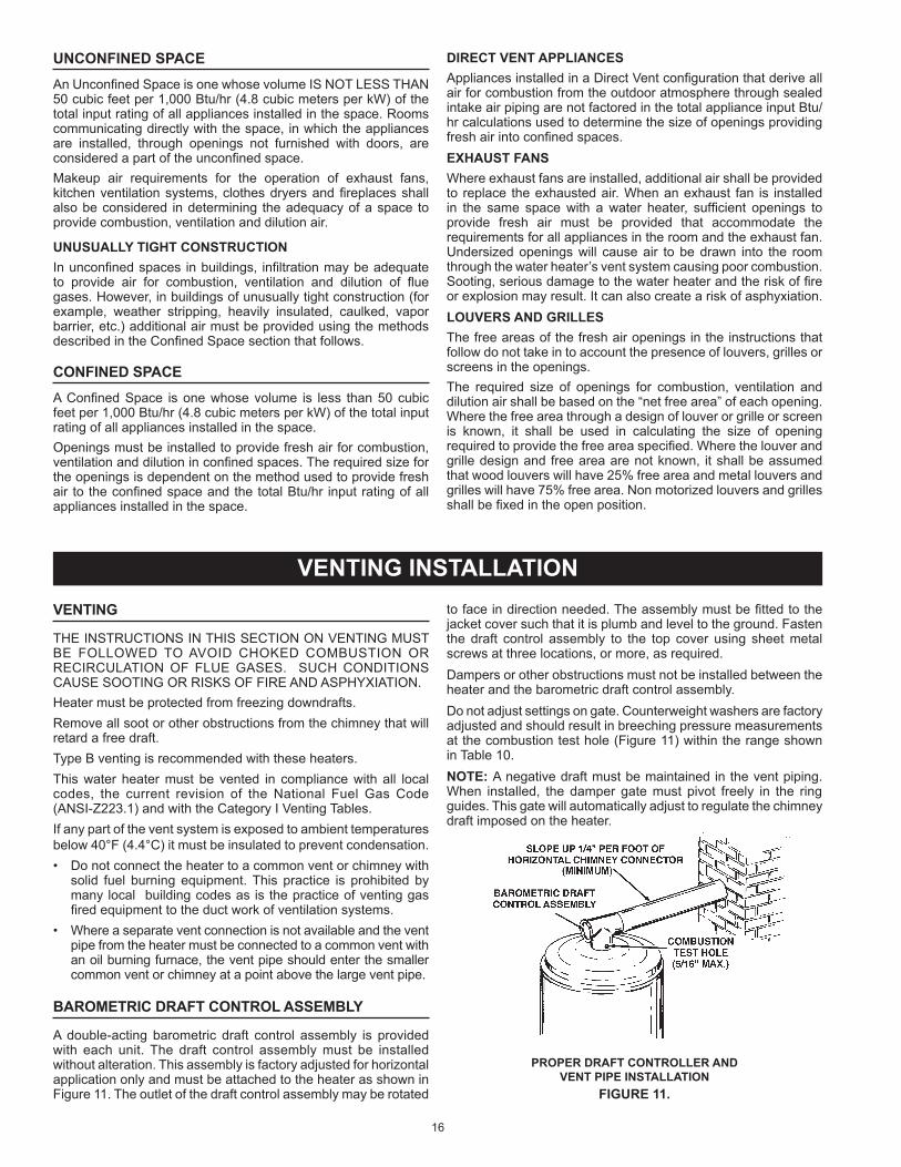
A double-a ting barometri draft ontrol assembly is provided with ea h unit The draft ontrol assembly must be installed without alteration This assembly is fa tory adjusted for horizontal appli ation only and must be atta hed to the heater as shown in Figure 11 The outlet of the draft ontrol assembly may be rotated
to fa e in dire tion needed The assembly must be tted to the ja ket over su h that it is plumb and level to the ground Fasten the draft ontrol assembly to the top over using sheet metal s rews at three lo ations, or more, as requiredDampers or other obstru tions must not be installed between the heater and the barometri draft ontrol assemblyDo not adjust settings on gate Counterweight washers are fa tory adjusted and should result in bree hing pressure measurements at the ombustion test hole (Figure 11) within the range shown in Table 10NOTE: A negative draft must be maintained in the vent piping When installed, the damper gate must pivot freely in the ring guides This gate will automati ally adjust to regulate the himney draft imposed on the heater
PROPER DRAFT CONTROLLER AND VENT PIPE INSTALLATION
FIGURE 11.
17
FRESH AIR OPENINGS FOR CONFINED SPACES
The following instru tions shall be used to al ulate the size, number and pla ement of openings providing fresh air for ombustion, ventilation and dilution in on ned spa es The
illustrations shown in this se tion of the manual are a referen e for the openings that provide fresh air into on ned spa es only DO NOT refer to these illustrations for the purpose of vent installation See Venting Installation on page 16 for omplete venting installation instru tions
OUTDOOR AIR THROUGH TWO OPENINGS
FIGURE 12.
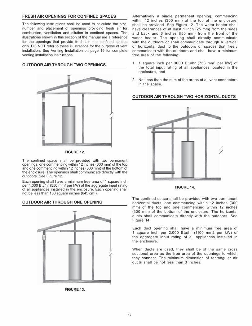
The on ned spa e shall be provided with two permanent openings, one ommen ing within 12 in hes (300 mm) of the top and one ommen ing within 12 in hes (300 mm) of the bottom of the en losure The openings shall ommuni ate dire tly with the outdoors See Figure 12Ea h opening shall have a minimum free area of 1 square in h per 4,000 Btu/hr (550 mm2 per kW) of the aggregate input rating of all applian es installed in the en losure Ea h opening shall not be less than 100 square in hes (645 m2)
OUTDOOR AIR THROUGH ONE OPENING
FIGURE 13.
Alternatively a single permanent opening, ommen ing within 12 in hes (300 mm) of the top of the en losure, shall be provided See Figure 12 The water heater shall have learan es of at least 1 in h (25 mm) from the sides and ba k and 6 in hes (l50 mm) from the front of the water heater The opening shall dire tly ommuni ate with the outdoors or shall ommuni ate through a verti al or horizontal du t to the outdoors or spa es that freely ommuni ate with the outdoors and shall have a minimum
free area of the following
1 1 square in h per 3000 Btu/hr (733 mm2 per kW) of the total input rating of all applian es lo ated in the en losure, and
2 Not less than the sum of the areas of all vent onne tors in the spa e
OUTDOOR AIR THROUGH TWO HORIZONTAL DUCTS
FIGURE 14.
The onfined spa e shall be provided with two permanent horizontal du ts, one ommen ing within 12 in hes (300 mm) of the top and one ommen ing within 12 in hes (300 mm) of the bottom of the en losure The horizontal du ts shall ommuni ate dire tly with the outdoors See Figure 14
Ea h du t opening shall have a minimum free area of 1 square in h per 2,000 Btu/hr (1100 mm2 per kW) of the aggregate input rating of all applian es installed in the en losure
When du ts are used, they shall be of the same ross se tional area as the free area of the openings to whi h they onne t The minimum dimension of re tangular air du ts shall be not less than 3 in hes

18
When du ts are used, they shall be of the same ross se tional area as the free area of the openings to whi h they onne t The minimum dimension of re tangular air du ts shall be not less than 3" (76 2 mm)
AIR FROM OTHER INDOOR SPACES
FIGURE 16.
The on ned spa e shall be provided with two permanent openings, one ommen ing within 12 in hes (300 mm) of the top and one ommen ing within 12 in hes (300 mm) of the bottom of the en losure See Figure 16Ea h opening shall ommuni ate dire tly with an additional room(s) of suf ient volume so that the ombined volume of all spa es meets the riteria for an Un on ned Spa eEa h opening shall have a minimum free area of 1 square in h per 1,000 Btu/hr (2200 mm2 per kW) of the aggregate input rating of all applian es installed in the en losure Ea h opening shall not be less than 100 square in hes (645 m2)
OUTDOOR AIR THROUGH TWO VERTICAL DUCTSThe illustrations shown in this se tion of the manual are a referen e for the openings that provide fresh air into on ned spa es only
DO NOT refer to these illustrations for the purpose of vent installation See Venting Installation on page 14 for omplete venting installation instru tions
FIGURE 15.
The on ned spa e shall be provided with two permanent verti al du ts, one ommen ing within 12 in hes (300 mm) of the top and one ommen ing within 12 in hes (300 mm) of the bottom of the en losure The verti al du ts shall ommuni ate dire tly with the outdoors See Figure 15
Ea h du t opening shall have a minimum free area of 1 square in h per 4,000 Btu/hr (550 mm2 per kW) of the aggregate input rating of all applian es installed in the en losure

19
Where an existing himney or vent is to be used, be sure that the himney or vent has adequate apa ity for the number and sizes of gas applian es being vented through it Inspe t the himney or vent and remove all soot or other obstru tions whi h will retard free draft
Vent onne tors making horizontal runs must have a minimum upward slope toward the himney or vent of 1/4 in h per foot Vent onne tor length should be kept as short as possible Be sure that the vent pipe does not extend beyond the inside wall of a himney
In venting systems where a ontinuous or intermittent ba k (positive) draft is found to exist, the ause must be determined and orre ted In some ases, a spe ial vent ap may be required Do not install this unit on the positive draft side of a venting system being served by a power exhauster
WATER HEATER INSTALLATION
VENT CONNECTION
Vent onne tions must be made to an adequate sta k or himney Refer to the National Fuel Gas Code ( urrent edition) or to the vent pipe manufa turer s gas vent and himney sizing table to properly design and size the venting
system Refer to Table 7 for the vent pipe size required for installation to the barometri draft ontrol assembly outlet
TABLE 7. BAROMETRIC DRAFT CONTROLASSEMBLY OUTLET SIZE
MODEL DRAFT CONTROL OUTLET DIAMETER
BTP-139/A BTP-199/A BTP-270/A BTP-370/A
6 6 8 8
WATER PIPING DIAGRAMS
This manual provides detailed water piping diagrams for typi al methods of appli ation for the water heaters, see Water Piping Diagrams beginning on page 35
The water heater may be installed by itself, or with a separate storage tank When used with a separate storage tank, the ir ulation may be either by gravity or by means of ir ulating
pump Adjust ow by throttling a full port ball valve installed in the ir ulating line on the outlet side of the pump Never throttle ow
on the su tion side of a pump See the Water Piping Diagrams beginning on page 35
NOTE: In addition to the fa tory installed Temperature-Pressure Relief Valve (T&P valve) on the water heater, ea h remote storage tank that may be installed and piped to a water heating applian e must also have its own properly sized, rated and approved Temperature-Pressure Relief Valve installed
Call the toll free te hni al support phone number listed on the ba k over of this manual for further assistan e in sizing a T&P valve for remote storage tanks
T&P VALVE DISCHARGE PIPE
Explosion Hazard
Temperature-Pressure Relief Valvemust comply with ANSI Z21.22-CSA 4.4 and ASME code.
Properly sized temperature-pressure relief valve must beinstalled in opening provided.
Can result in overheating andexcessive tank pressure.
Can cause serious injury or death.
WATER LINE CONNECTIONS
The water piping installation must onform to these instru tions and to all lo al ode authority having jurisdi tion Good pra ti e requires that all heavy piping be supported
Read and observe all requirements in the following se tions before installation of the water piping begins
1 Water Temperature Control and Mixing Valves on page 13
2 Dishwashing Ma hines on page 14
3 Temperature-Pressure Relief Valve on page 14-15
4 Closed Systems and Thermal Expansion on page 14
5 For multiple water heater installations see Water Piping Diagrams beginning on page 35
WATER (POTABLE) HEATING AND SPACE HEATING
1 All piping omponents onne ted to this unit for spa e heating appli ations shall be suitable for use with potable water
2 Toxi hemi als, su h as those used for boiler treatment, shall NEVER be introdu ed into this system
3 This unit may NEVER be onne ted to any existing heating system or omponent(s) previously used with a non-potable water heating applian e
4 When the system requires water for spa e heating at temperatures higher than required for domesti water purposes, a tempering valve must be installed Please refer to installation diagrams beginning on page 35 of this manual for suggested piping arrangements
5 These water heaters annot be used in spa e heating appli ations only
THERMOMETERS (NOT SUPPLIED)
Thermometers should be obtained and eld installed as shown in the installation diagrams
Thermometers are installed in the system as a means of dete ting the temperature of the outlet water supply

20
This water heater is provided with a properly rated/sized and erti ed ombination temperature - pressure (T&P) relief valve
by the manufa turer See Temperature-Pressure Relief Valve on pages 14-15 for information on repla ement and other requirements
Water Damage Hazard
Temperature-Pressure Relief Valve dischargepipe must terminate at adequate drain.
CAUTION
Install a dis harge pipe between the T&P valve dis harge opening and a suitable oor drain Do not onne t dis harge piping dire tly to the drain unless a 6 (15 2 m) air gap is provided To prevent bodily injury, hazard to life, or property damage, the relief valve must be allowed to dis harge water in adequate quantities should ir umstan es demand If the dis harge pipe is not onne ted to a drain or other suitable means, the water ow may ause property damage
T&P VALVE DISCHARGE PIPE REQUIREMENTS:
Shall not be smaller in size than the outlet pipe size of the valve, or have any redu ing ouplings or other restri tions
Shall not be plugged or blo ked
Shall not be exposed to freezing temperatures
Shall be of material listed for hot water distribution
Shall be installed so as to allow omplete drainage of both Temperature-Pressure Relief Valve and the dis harge pipe
Must terminate a maximum of six in hes above a oor drain or external to the building In old limates, it is re ommended that the dis harge pipe be terminated at an adequate drain inside the building
Shall not have any valve or other obstru tion between the relief valve and the drain
INSTALLATION DIAGRAMS - TOP INLET/OUTLET USAGE
Use of the top inlet water onne tion requires an inlet dip tube (refer to Figure 17) The tube is supplied in the heater Follow aution labels if applying heat to this tting Do not allow pipe
dope to onta t the plasti tube during installation
TUBE INLET INSTALLATION
FIGURE 17.
BURNER INSTALLATION
Remove the fa tory-installed insulation overing the ombustion hamber opening (A utility knife is useful for utting out the
insulation) Cut the insulation ba k even with the ja ket opening Install the ange gasket (whi h is usually taped to the heater ja ket) over the three bolts protruding from the tank at the ombustion hamber opening
Remove hardware (3 hex nuts, 3 at washers, and 3 lo k washers) from the shipping bag atta hed to the heater s ele tri al onduit
Begin assembling the power burner to the tank by pla ing the power burner nozzle in the ombustion hamber opening Slide the nozzle into the tank and rotate the mounting ange to engage the mounting bolts, refer to Figure 18 Then, pla e the at washers followed by the lo k washers, and nally the hex nuts on the mounting bolts Hand tighten the nuts Then gradually tighten ea h nut alternating between the 3 mounting bolts Do not over tighten as damage to the ange gasket or to the tank may result Refer to Figure 18
POWER BURNER INSTALLATIONFIGURE 18.

21
HEATER WIRING
All ele tri al work must be installed in a ordan e with the urrent edition of the National Ele tri al Code ANSI/NFPA No 70 or Canadian Ele tri al Code CSA C22 1 and must onform to all lo al ode authority having jurisdi tion AN ELECTRICAL GROUND IS REQUIRED TO REDUCE RISK OF ELECTRICAL SHOCK OR POSSIBLE ELECTROCUTION
If any of the original wire as supplied with the water heater must be repla ed, use only type 105 C thermoplasti or equivalent 2500C type F must be used for the ame sensor and igniter leads
The ontrols of this water heater are polarity sensitive Be ertain to properly wire the hot and neutral onne tions
FIGURE 19.

22
GAS PIPING
Conta t your lo al gas servi e ompany to ensure that adequate gas servi e is available and to review appli able installation odes for your area
Size the main gas line in a ordan e with Table 8 The gures shown are for straight lengths of pipe at 0 5 in W C pressure drop, whi h is onsidered normal for low pressure systems Note Fittings su h as
elbows, tees and line regulators will add to the pipe pressure drop Also refer to the latest version of the National Fuel Gas Code
S hedule 40 Steel or Wrought Iron Pipe is the preferred material for the gas line of this water heater It is imperative to follow the sizing re ommendations in the latest version of the National Fuel Gas Code if Corrugated Stainless Steel Tubing (CSST) is used as the gas line for this water heater
The heater is not intended for operation at higher than 14 0" W C - natural gas, (1/2 pound per square in h gage) supply gas pressure Exposure to higher supply pressure may ause damage to the gas valve whi h ould result in re or explosion If overpressure has o urred su h as through improper testing of gas lines or emergen y malfun tion of the supply system, the gas valve must be he ked for safe operation Make sure that the outside vents on the
supply regulators and the safety vent valves are prote ted against blo kage These are parts of the gas supply system, not the heater Vent blo kage may o ur during i e storms
TABLE 8. MAXIMUM CAPACITY OF PIPE IN CUBIC FEET OF GAS PER HOUR
(Based upon a Pressure Drop of 0 5 in h Water Column and0 6 Spe i Gravity Gas and max gas pressure of 5 psig)
LENGTH IN FEET
NOMINAL IRON PIPE SIZE (INCHES)
1/2 3/4 1 1 1/4 1 1/2 2 2 1/2 3 4
10 175 360 680 1,400 2,100 3,950 6,300 11,000 23,000
20 120 250 465 950 1,460 2,750 4,350 7,700 15,800
30 97 200 375 770 1,180 2,200 3,520 6 250 12 800
40 82 170 320 660 990 1,900 3,000 5,300 10,900
50 73 151 285 580 900 1,680 2,650 4,750 9,700
60 66 138 260 530 810 1,520 2,400 4,300 8,800
70 61 125 240 490 750 1,400 2,250 3,900 8,100
80 57 118 220 460 690 1,300 2,050 3,700 7,500
90 53 110 205 430 650 1,220 1,950 3,450 7,200
100 50 103 195 400 620 1,150 1,850 3,250 6,700
125 44 93 175 360 550 1,020 1,650 2,950 6,000
150 40 84 160 325 500 950 1,500 2,650 5,500
175 37 77 145 300 460 850 1,370 2,450 5,000
200 35 72 135 280 430 800 1,280 2,280 4,600
It is important to guard against gas valve fouling from ontaminants in gas ways Su h fouling may ause improper operation, re or explosion
If opper supply lines are used they must be internally tinned and erti ed for gas servi e Before atta hing the gas line, be sure that
all gas pipe is lean on the inside
To trap any dirt or foreign material in the gas supply line, a sediment trap must be in orporated in the piping (see Figure 20) The sediment trap must be readily a essible and not subje t to freezing onditions Install in a ordan e with re ommendations of serving gas suppliers Refer to the latest version of the National Fuel Gas Code
To prevent damage, are must be taken not to apply too mu h torque when atta hing gas supply pipe to gas valve inlet
Apply joint ompounds (pipe dope) sparingly and only to the male threads of pipe joints Do not apply ompounds to the rst two threads Use ompounds resistant to the a tion of lique ed petroleum gases
GAS METER SIZE – NATURAL GASES ONLYBe sure the gas meter has suf ient apa ity to supply the full rated gas input of the water heater as well as the requirements of all other gas red equipment supplied by the meter If gas meter is too small, ask the gas ompany to install a larger meter having adequate apa ity
GAS PIPING AND SEDIMENT TRAP INSTALLATION
FIGURE 20.
GAS LINE LEAK TESTING
Fire and Explosion Hazard
Leak test before placing the waterheater in operation.Disconnect gas piping and main gasshutoff valve before leak testing.Install sediment trap in accordancewith NFPA 54.
Use joint compound or Teflon tapecompatible with propane gas.
Any time work is done on the gas supply system perform a leak test to avoid the possibility of re or explosion
1 For test pressures ex eeding 1/2 psi (3 45 kPa) dis onne t the water heater and its Main Gas Shutoff Valve from the gas supply piping system during testing, see Figure 20 The gas supply line must be apped when dis onne ted from the water heater
2 For test pressures of 1/2 psi (3 45 kpa) or less, the water heater need not be dis onne ted, but must be isolated from the supply gas line by losing the Main Gas Shutoff Valve during testing
3 Coat all supply gas line joints and onne tions upstream of the water heater with a non- orrosive soap and water solution to test for leaks Bubbles indi ate a gas leak Do not use mat hes, andles, ame or other sour es of ignition for this purpose
4 Repair any leaks before pla ing the water heater in operation
PURGING
Gas line purging is required with new piping or systems in whi h air has enteredPurging should be performed per the urrent edition of NFPA 54 the National Fuel Gas Code

23
7 If the Ignition Control does not sense the ame during the 4 se ond ignition trial period, the Ignition Control shuts the Gas Valve and turns off the Spark Igniter The ontrol is lo ked out, the power to the unit must be y led to restart the Ignition Control
8 If the ignition ontrol senses ame during the 4 se onds trial for ignition period, the gas ontrol remains open and the burner on until the all for heat ends
9 The Ignition Control monitors the Flame Sensor during the heating y le If the flame signal is lost, the Ignition Control shuts the Main Gas Valve and re-starts the ignition pro ess at step 4
10 On e the unit is satis ed, the Ignition Control will shut off the Main Gas Valve and the unit will be in standby mode until another all for heat is initiated by the thermostat
See the ow hart on page 26 for more information
Atta h a gas pressure gauge or manometer to upstream side of main gas o k and a gas pressure gauge or manometer to the manifold pressure tapping Che k voltage at dis onne t swit h to make ertain that it
mat hes that shown on the burner label Apply a few drops of No 20 SAE non-detergent oil to the
motor bearings Drill max 5/16" hole in bree hing as lose as possible to ue
onne tion on heater to install sta k thermometer and ombustion analyzing equipment (See Figure 11) You are now ready to begin the burner start up pro edure
Installation and start up of this water heater requires abilities and skills equivalent to that of a li ensed tradesman in the eld involved, see Quali ations on page 6
Do not pla e the water heater in operation if any part has been under water Immediately all a quali ed servi e te hni ian to inspe t the water heater and to repla e any part of the ontrol system and any gas ontrol whi h has been under water Light the water heater in a ordan e with the Lighting and Operation Instru tion label on the water heater and in this manual on pages 25 Before attempting start up, thoroughly study and know the exa t Sequen e Of Operation See written Sequen e Of Operation on page 23 and Sequen e Of Operation Flow Chart on page 24Be ertain that the water heater is full of water, that air is purged from the gas and water lines and that there are no leaks in the gas and water lines Ensure all inlet water valves are open
FILLING THE WATER HEATERFollow these steps to ll the water heater prior to start up1 Close the heater drain valve2 Open a nearby hot water fau et to permit air in system to es ape3 Fully open the old water inlet valve allowing the piping and water heater to ll with water4 Close hot water fau et opened in Step 2 as water starts to owRead SEQUENCE OF OPERATION se tion of this manual prior to lighting and operating this water heaterWith above onditions satis ed, start the unit in a ordan e with the instru tions on the operating label atta hed to the heater For your onvenien e a opy of the instru tions are shown on pages 25
Fire or Explosion Hazard
Read instruction manual beforeinstalling, using or servicing
water heater.
To avoid risk of fire or explosion purge discharge must notenter into confined areas or spaces where ignition can occur.
The area must be well ventilated and all sources of ignitionmust be deactivated or removed.
Gas line purging is required with new piping or systems inwhich air has entered.
PRIOR TO START UP
This produ t requires a formal Start-Up by an authorized servi e/ start-up provider that has been approved by the manufa turer for this spe i produ t Call 1-800-527-1953 to lo ate the nearest authorized start-up provider and arrange a fa tory start-up Please provide as mu h noti e as possible, preferably 2 weeks Please have the model and serial number ready when you allThis start-up is required to a tivate the warranty and ensure safe, ef ient operationWarranty on this produ t is limited and ould be void in the event the unit is not installed per the instru tions in this manual and/or not started up by an authorized fa tory trained servi e/start-up providerThe following test equipment should be on hand (all test equipment must be a limated to ambient temperature before alibration and use )1 CO2 indi ator (Fyrite or similar) or O2 analyzer2 CO indi ator (Monoxor or similar)3 Sta k thermometer4 Draft Gauge or in lined manometer5 Two U-tube manometers or alibrated 0-10" and 0-35" w pressure gauges6 Combination volt/ammeter
START-UP AND OPERATION
SEQUENCE OF OPERATIONThe following information will des ribe the Sequen e of Operation for this water heater
1 Swit h power on to unit
2 Thermostat alls for heat
3 On a all for heat, 24V is applied to motor start relay and air swit h On e the fan motor rea hes operating rpm ombustion air pressure is sensed by the air proving swit h and loses the swit h onta ts energizing the S89 ignition module The ignition module performs diagnosti self he k on system omponents
4 The Ignition Control begins the trial for ignition after 30 se onds prepurge is ompleted
5 The Ignition Control turns on the Spark Igniter and opens the Pilot Gas Valve
6 The Ignition Control monitors the Flame Sensor during the ignition trial period
24
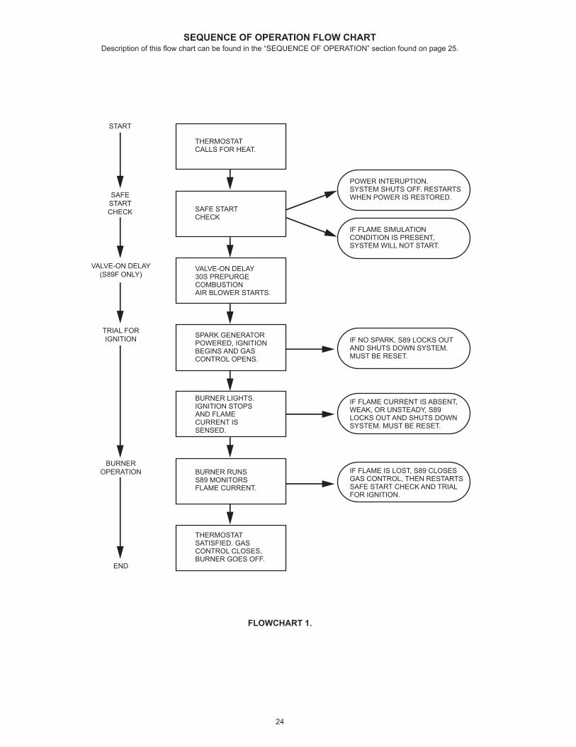
SEQUENCE OF OPERATION FLOW CHARTDes ription of this ow hart an be found in the SEQUENCE OF OPERATION se tion found on page 25
FLOWCHART 1.
START
THERMOSTATCALLS FOR HEAT.
IF FLAME IS LOST, S89 CLOSESGAS CONTROL, THEN RESTARTSSAFE START CHECK AND TRIALFOR IGNITION.
IF FLAME CURRENT IS ABSENT,WEAK, OR UNSTEADY, S89LOCKS OUT AND SHUTS DOWNSYSTEM. MUST BE RESET.
IF NO SPARK, S89 LOCKS OUTAND SHUTS DOWN SYSTEM.MUST BE RESET.
IF FLAME SIMULATIONCONDITION IS PRESENT,SYSTEM WILL NOT START.
POWER INTERUPTION.SYSTEM SHUTS OFF. RESTARTSWHEN POWER IS RESTORED.
SAFE STARTCHECK
VALVE-ON DELAY30S PREPURGECOMBUSTIONAIR BLOWER STARTS.
SPARK GENERATORPOWERED, IGNITIONBEGINS AND GASCONTROL OPENS.
BURNER LIGHTS.IGNITION STOPSAND FLAMECURRENT IS SENSED.
BURNER RUNSS89 MONITORSFLAME CURRENT.
THERMOSTATSATISFIED. GASCONTROL CLOSES,BURNER GOES OFF.
SAFESTARTCHECK
VALVE-ON DELAY(S89F ONLY)
TRIAL FORIGNITION
BURNEROPERATION
END

25
LIGHTING & OPERATION LABEL
FIGURE 21. LABEL FOR NATURAL AND LP GAS MODELS
26
ADJUSTMENTS
1 Che k gas line pressure and manifold pressure (table 10) and adjust as required
2 Che k barometri damper for proper operation Parts must move freely
3 Allow the unit to operate for 15 minutes Drain hot water from the heater or storage tank to ontinue main burner operation
4 Determine heat input rate (see CHECKING THE INPUT se tion below)
CHECKING VENTING
The following steps shall be followed with ea h applian e onne ted to the venting system pla ed in operation, while
any other applian es onne ted to the venting system are not in operation
1 Seal any unused openings in the venting system
2 Inspe t the venting system for proper size and horizontal pit h, as required in the National Fuel Gas Code, ANSI Z223 1or the CAN/CGA B149 Installation Codes and these instru tions Determine that there is no blo kage or restri tion, leakage, orrosion and other defi ien ies whi h ould ause an unsafe ondition
3 So far as is pra ti al, lose all building doors and windows and all doors between the spa e in whi h the water heater(s) onne ted to the venting system are lo ated and other spa es of the building Turn on all applian es not onne ted to the venting system Turn on all exhaust fans,
su h as range hoods and bathroom exhausts, so they shall operate at maximum speed Close firepla e dampers
4 Follow the lighting instru tion Pla e the water heater in operation Adjust thermostat so water heater shall operate ontinuously
5 After it has been determined that ea h applian e onne ted to the venting system properly vents when tested as outlined above, return doors, windows, exhaust fans, firepla e dampers and any other gas burning applian e to their previous onditions of use
6 If improper venting is observed during any of the above tests, the venting system must be orre ted
FAILURE TO CORRECT BACK DRAFTS MAY CAUSE AIR CONTAMINATION AND UNSAFE CONDITIONS If the ba k draft annot be orre ted by the normal method
or if a suitable draft annot be obtained, a blower type flue gas exhauster must be employed to assure proper venting and orre t ombustion
CHECKING THE INPUT
For installation lo ations with elevations above 2000 feet, refer to HIGH ALTITUDE INSTALLATIONS se tion of this manual for input redu tion pro edureThe input rate an be estimated by timing the meter, if no other applian es are operatingWith a stopwat h, or a wristwat h, whi h an display the time in se onds, read the gas meter and measure the amount of
time required for the heater to onsume 5 ubi feet of gas The a tual rate may then be estimated by using the formula below
(3600/T) x H Btuh
T Time in se onds to burn one ubi foot of gas
H Btu s per ubi foot of gas
Btuh A tual heater input
Example
T 15 1 se onds
H 1050 Btu
Btuh
(3600/15 1) x 1050 250,000
The input may be adjusted by adjusting the pressure regulator Remove the top ap to expose the adjustment s rew Turning the s rew in in reases the gas pressure and ba king the s rew out de reases the pressure Do not turn the adjusting s rew in past the point where no further in rease in pressure is noted
The manifold pressure is measured at the manifold pressure tap, see figure 7, and should be used as a referen e point for making pressure regulator adjustments Table 6 gives the design manifold pressures for ea h model In rease or redu e the pressure as required to obtain the rated input
If an a eptable rate annot be a hieved by adjusting the pressure regulator (manifold pressure), first he k to be ertain that the gas supply pressure to the unit is adequate
If the supply pressure is inadequate, a different burner orifi e may be required Obtain from the utility the heating value and spe ifi gravity of the gas at the site Provide this information and the altitude of the site to obtain a larger orifi e size
UNDER NO CIRCUMSTANCES SHOULD THE GAS INPUT EXCEED THE INPUT SHOWN ON THE HEATER MODEL AND RATING PLATE OVERFIRING COULD RESULT IN DAMAGE OR SOOTING OF THE HEATER
TABLE 9.APPROXIMATE TIME REQUIRED TO CONSUME
1 CU. FT. OF GAS AT FULL CAPACITY
INPUT RATE
(BTUH)INPUT
BTUH PER
CU. FT.
TIMES (for Natural gas in Sec.)
TIMES (for LP gas
in Sec.)
BTP-139 139000 1050 2500 27 2 64 7
BTP-199 199000 1050 2500 19 0 45 2
BTP-270 270000 1050 2500 14 0 33 3
BTP-370 370000 1050 2500 10 2 24 3

27
TABLE 10.NOMINAL START-UP SPECIFICATIONS
MODEL BTP 139/A
BTP 199/A
BTP 270/A
BTP 370/A
Max Gas Line Press (W C ) Nat Gas - 10 5 W C /Prop Gas -13 0 Manifold Press (W C )
Natural Gas 3 5 3 5 3 5 3 5 Propane Gas 3 5 3 5 3 5 3 5
Ori e Natural Gas 0 24 0 308 0 386 0 532 Propane Gas 0 209 0 257 0 302 0 368
Air Shutter Setting No Natural Gas 2 5 5 75 4 3 Propane Gas 4 5 10 4 8 5
CO 9 2 9 8 7 5 8 0 CO Parts Per Million <200 <200 <200 <200
Gross Sta k Temp ( F) 305 338 405 488Bree hing Press (in hes W C ) Ranges from - 0.02 to - 0.07 Inches Water Column
FIGURE 22.
SETTING BURNER OPERATION
Make ombustion measurements and orresponding air shutter adjustments per table 10 Combustion results from table 10 are for natural gas models
Pro eed with CO2 test of the ue gases with an Orsat or other similar ombustion test equipment If the CO2 ontent is within range (see table 6) no adjustment of the air shutter is required Flue gas temperature and CO2 measurements should be repeated 3 times to ensure a urate readings
Che k the ue gas temperature ahead of the barometri damper See table 10 (net temp gross temp ambient temp )
Che k bree hing pressure and the barometri damper ontrol to make sure it operates freely and there is no dis harge of ue produ ts into the room
Che k main burner operation by y ling on and off the thermostat dial several times Wait 1 minute between y les for regulators and sequen ing to reset
When all adjustments are satisfa tory
Fill in part no 196793 Start-up form
Adjust thermostat temperature dial to deliver desired water temperature at point of use
For subsequent normal starting and shutoff pro edure, see LIGHTING and OPERATION LABEL on page 25
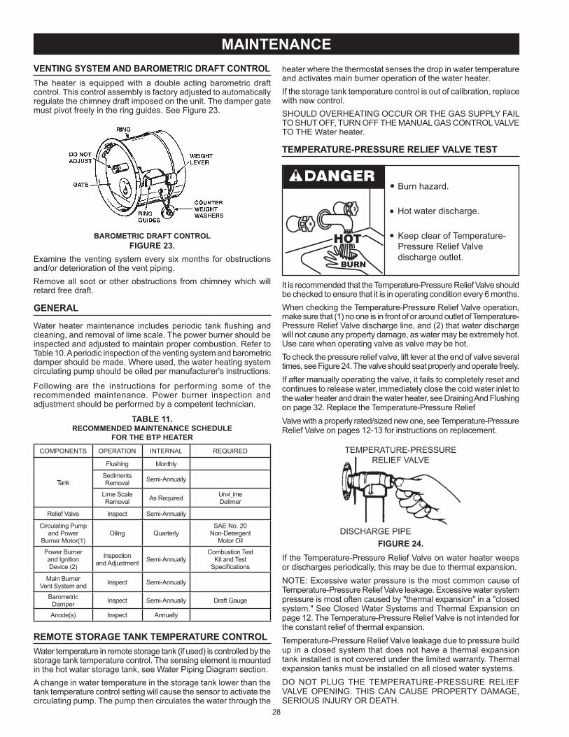
28
heater where the thermostat senses the drop in water temperature and a tivates main burner operation of the water heaterIf the storage tank temperature ontrol is out of alibration, repla e with new ontrolSHOULD OVERHEATING OCCUR OR THE GAS SUPPLY FAIL TO SHUT OFF, TURN OFF THE MANUAL GAS CONTROL VALVE TO THE Water heater
TEMPERATURE-PRESSURE RELIEF VALVE TEST
Burn hazard
Hot water dis harge
Keep lear of Temperature-Pressure Relief Valvedis harge outlet
It is re ommended that the Temperature-Pressure Relief Valve should be he ked to ensure that it is in operating ondition every 6 monthsWhen he king the Temperature-Pressure Relief Valve operation, make sure that (1) no one is in front of or around outlet of Temperature-Pressure Relief Valve dis harge line, and (2) that water dis harge will not ause any property damage, as water may be extremely hot Use are when operating valve as valve may be hotTo he k the pressure relief valve, lift lever at the end of valve several times, see Figure 24 The valve should seat properly and operate freelyIf after manually operating the valve, it fails to ompletely reset and ontinues to release water, immediately lose the old water inlet to
the water heater and drain the water heater, see Draining And Flushing on page 32 Repla e the Temperature-Pressure Relief Valve with a properly rated/sized new one, see Temperature-Pressure Relief Valve on pages 12-13 for instru tions on repla ement
FIGURE 24.If the Temperature-Pressure Relief Valve on water heater weeps or dis harges periodi ally, this may be due to thermal expansionNOTE Ex essive water pressure is the most ommon ause of Temperature-Pressure Relief Valve leakage Ex essive water system pressure is most often aused by "thermal expansion" in a " losed system " See Closed Water Systems and Thermal Expansion on page 12 The Temperature-Pressure Relief Valve is not intended for the onstant relief of thermal expansionTemperature-Pressure Relief Valve leakage due to pressure build up in a losed system that does not have a thermal expansion tank installed is not overed under the limited warranty Thermal expansion tanks must be installed on all losed water systemsDO NOT PLUG THE TEMPERATURE-PRESSURE RELIEF VALVE OPENING THIS CAN CAUSE PROPERTY DAMAGE, SERIOUS INJURY OR DEATH
VENTING SYSTEM AND BAROMETRIC DRAFT CONTROLThe heater is equipped with a double a ting barometri draft ontrol This ontrol assembly is fa tory adjusted to automati ally
regulate the himney draft imposed on the unit The damper gate must pivot freely in the ring guides See Figure 23
BAROMETRIC DRAFT CONTROLFIGURE 23.
Examine the venting system every six months for obstru tions and/or deterioration of the vent pipingRemove all soot or other obstru tions from himney whi h will retard free draft
GENERAL
Water heater maintenan e in ludes periodi tank ushing and leaning, and removal of lime s ale The power burner should be
inspe ted and adjusted to maintain proper ombustion Refer to Table 10 A periodi inspe tion of the venting system and barometri damper should be made Where used, the water heating system ir ulating pump should be oiled per manufa turer s instru tions
Following are the instru tions for performing some of the re ommended maintenan e Power burner inspe tion and adjustment should be performed by a ompetent te hni ian
TABLE 11.RECOMMENDED MAINTENANCE SCHEDULE
FOR THE BTP HEATER
COMPONENTS OPERATION INTERNAL REQUIRED
Tank
Flushing Monthly
Sediments Removal Semi-Annually
Lime S ale Removal As Required Un»l_ime
Delimer
Relief Valve Inspe t Semi-Annually
Cir ulating Pump and Power
Burner Motor(1)Oiling Quarterly
SAE No 20 Non-Detergent
Motor Oil
Power Burner and Ignition Devi e (2)
Inspe tion and Adjustment Semi-Annually
Combustion Test Kit and Test
Spe i ations
Main Burner Vent System and Inspe t Semi-Annually
Barometri Damper Inspe t Semi-Annually Draft Gauge
Anode(s) Inspe t Annually
REMOTE STORAGE TANK TEMPERATURE CONTROLWater temperature in remote storage tank (if used) is ontrolled by the storage tank temperature ontrol The sensing element is mounted in the hot water storage tank, see Water Piping Diagram se tionA hange in water temperature in the storage tank lower than the tank temperature ontrol setting will ause the sensor to a tivate the ir ulating pump The pump then ir ulates the water through the
MAINTENANCE

29
It is re ommended that the water heater storage tank be drained and ushed every 6 months to redu e sediment buildup The water heater should be drained if being shut down during freezing temperatures See Features And Components in this manual for the lo ation of the water heater omponents des ribed belowTO DRAIN THE WATER HEATER STORAGE TANK:1 Turn off the ele tri al supply to the water heater2 Turn off the gas supply at the Main Gas Shutoff Valve if the
water heater is going to be shut down for an extended period3 Ensure the old water inlet valve is open4 Open a nearby hot water fau et and let the water run until the
water is no longer hot5 Close the old water inlet valve to the water heater6 Conne t a hose to the water heater drain valve and terminate
it to an adequate drain7 Open the water heater drain valve and allow all the water to
drain from the storage tank8 Close the water heater drain valve when all water in the
storage tank has drained9 Close the hot water fau et opened in Step 410 If the water heater is going to be shut down for an extended
period, the drain valve should be left open
TO FLUSH THE WATER HEATER STORAGE TANK:1 Turn off the ele tri al supply to the water heater2 Ensure the old water inlet valve is open3 Open a nearby hot water fau et and let the water run until the
water is no longer hot Then lose the hot water fau et4 Conne t a hose to the drain valve and terminate it to an
adequate drain5 Ensure the drain hose is se ured before and during the entire
ushing pro edure Flushing is performed with system water pressure applied to the water heater
6 Open the water heater drain valve to ush the storage tank7 Flush the water heater storage tank to remove sediment and
allow the water to ow until it runs lean8 Close the water heater drain valve when ushing is ompleted9 Remove the drain hose10 Fill the water heater - see Filling The Water Heater in this manual11 Turn on ele tri al supply to pla e water heater ba k in operation12 Allow the water heater to omplete several heating y les to
ensure it is operating properly
RECOMMENDED PROCEDURE FOR PERIODIC REMOVAL OF LIME DEPOSITS FROM TANK TYPE COMMERCIAL WATER HEATERSThe amount of al ium arbonate (lime) released from water is in dire t proportion to water temperature and usage, see hart The higher the water temperature or water usage, the more lime deposits are dropped out of the water This is the lime s ale whi h forms in pipes, heaters and on ooking utensilsLime a umulation not only redu es the life of equipment but also redu es ef ien y of the heater and in reases fuel onsumptionThe usage of water softening equipment greatly redu es the hardness of the water However, this equipment does not always remove all of the hardness (lime) For this reason it is re ommended that a regular s hedule for deliming be maintainedThe time between leaning will vary from weeks to months depending upon water onditions and usageThe depth of lime buildup should be measured periodi ally Heaters equipped with leanouts will have about 2" of lime buildup when the level of lime has rea hed the bottom of the leanout opening A s hedule for deliming should then be set up,based on the amount of time it would take for a 1" buildup of lime It is re ommended that the water heater initially be inspe ted after 6 monthsExample 1:Initial inspe tion after 6 months shows 1/2" of lime a umulation Therefore, the heater should be delimed on e a yearExample 2:Initial inspe tion after 6 months shows 2" of lime a umulation Therefore, the heater should be delimed every 3 months
Explosion HazardTemperature-Pressure Relief Valvemust comply with ANSI Z21.22-CSA 4.4 and ASME code.
Properly sized temperature-pressure relief valve must beinstalled in opening provided.
Can result in overheating andexcessive tank pressure.
Can cause serious injury or death.
ANODE ROD INSPECTION
Property Damage HazardAvoid water heater damage.Inspection and replacement of anode rod required.
CAUTION
The anode rod is used to prote t the tank from orrosion Most hot water tanks are equipped with an anode rod The submerged rod sa ri es itself to prote t the tank Instead of orroding tank, water ions atta k and eat away the anode rod This does not affe t water s taste or olor The rod must be maintained to keep tank in operating onditionAnode rod deterioration depends on water ondu tivity, not ne essarily water ondition A orroded or pitted anode rod indi ates high water ondu tivity and should be he ked and/or repla ed more often than an anode rod that appears to be inta t Repla ement of a depleted anode rod an extend the life of your water heater Inspe tion should be ondu ted by a quali ed te hni ian, and at a minimum should be he ked annually after warranty periodArti ially softened water is ex eedingly orrosive be ause the pro ess substitutes sodium ions for magnesium and al ium ionsUse of a water softener may de rease the life of water heater tankThe anode rod should be inspe ted after a maximum of three years and annually thereafter until ondition of anode rod di tates its repla ement Anode repla ement is not overed by warranty NOTE arti ially softened water requires the anode rod to be inspe ted annually
DRAINING AND FLUSHING
Burn harzard.
Hot water discharge.
Keep hands clear of drainvalve discharge.

30
Prepare the Water Heater
To delime the water heater using the Flo-Jug method, rst prepare the heater for deliming
Explosion Hazard
Flammable hydrogen gasesmay be present.
Keep all ignition sources awayfrom faucet when turning onhot water.
Do not smoke or have open ame or sparks in vi inity of heater Do not mix UN LIME with other hemi als Do not allow onta t with magnesium, aluminum or galvanized metals
Chemical Hazard
roduct contains phosphoric acid.
eep out of reach of children.
Use rubber or neoprene gloves.
Contains phosphori a id In ase of external onta t, ush with ool water If irritation persists, get medi al attention If swallowed,
give 1 or 2 glasses of water or milk and all physi ianGet immediate medi al attention for eyes Keep out of rea h of hildrenNOTE: THE USE OF RUBBER OR NEOPRENE GLOVES IS RECOMMENDED, ESPECIALLY IF YOU HAVE ANY OPEN SORES OR CUTS TO AVOID UNNECESSARY IRRITATION OR DISCOMFORT.1 Turn off fuel and/or power supply to heater Also, turn off power
to any ele tri al devi e or equipment, whi h is atta hed, or part of the system
2 Open hot water side of fau et losest to heater and allow water to run until it is ool enough to handle safely
3 Close old water inlet valve to heater4 Conne t hose to drain valve at bottom of heater and start draining
heater into suitable oor drain area5 Remove pressure relief valve while heater is draining NOTE
Do not repla e pressure relief valve until deliming is ompleted Pressure relief valve opening will also a t as a vent in ase of possible onta t between the delimer and the anode rod(s), whi h may produ e ammable hydrogen-air mixtures
6 If pressure relief valve appears to be limed-up, pla e it in a lean glass or plasti ontainer adequate in size so that you an pour enough UN LIME into ontainer to over the valve and allow spa e for foaming When foaming stops, run fresh ool water into the ontainer and rinse the pressure relief valve for a few minutes
7 If heater does not drain ompletely after a reasonable length of time, turn off the main water supply valve to stop water from entering the tank due to a by-pass problem or defe tive old water inlet valve Also, he k for logged drain valve opening Heater must be ompletely drained before introdu ing UN LIME
8 Remove the leanout over and pla e a lean plasti bu ket next to the leanout openingPartially open the old water inlet valve to allow time to a omplish the following and then lose the valve
FIGURE 25.
DELIMING SOLVENTSUN LIME is re ommended for deliming UN LIME is a patented food grade a id whi h is safe to handle and does not reate the harmful fumes whi h are asso iated with other produ tsUN LIME may be obtained from your dealer, distributor or water heater manufa turer Order Part Number 9005416105, 1 gallon, pa ked 4 gallons per ase or Part Number 9005417105, 5 gallon ontainerNOTE Un Lime is not available for use in CanadaHydro hlori base a ids are not re ommended for use on glass lined tanksObserve handling instru tions on label of produ t being used
TANK CLEANOUT PROCEDUREThe following pra ti es will ensure longer life and enable the unit to operate at its designed ef ien y1 On e a month the heater should be ushed Open drain valve
and allow two gallons of water to drain from heater Inlet water valve should remain open to maintain pressure in tank
2 A leanout opening is provided for periodi leaning of the tank Gas must be shut off and heater drained before opening leanout
To lean heater through leanout opening, pro eed as follows3 Drain heater4 Remove outer over plate from lower side of heater ja ket5 Remove six (6) hex head s rews se uring tank leanout plate
and remove plate6 Remove lime, s ale, or sediment using are not to damage
the glass lining7 Inspe t leanout plate gasket, if new gasket is required,
repla e with part no 90040992158 Install leanout plate Be sure to draw plate up tight by
tightening s rews se urely9 Repla e outer ja ket over plate In some water areas the sediment might not be removed by this method and may result in the water heater making rumbling or boiling noises To dissolve and remove these more stubborn mineral deposits, UN LIME Professional Delimer should be used
DELIMING USING FLO-JUG METHODUN LIME in the 5 gallon size is re ommended for deliming of all models Conta t your lo al dealer, distributor or, water heater manufa turer

31
Normally, lime removal will be ompleted within one hour Severe build-up of lime may take longer than an hour to omplete des aling
Note To he k UN LIME for ontinued use, pla e some s ale or white halk in a glass with a small amount of UN LIME If the material is vigorously dissolved by the UN LIME, it an be reused if not, the UN LIME should be repla ed
FIGURE 26.
POWER BURNERKeep the area around the burner lear and free of ombustible materials, gasoline or other ammable liquids or vapors Do not obstru t burner air openings or ventilation grilles for ombustion air
TYPICAL MAIN BURNER FLAMEFIGURE 27.
The main burner ames (Figure 27) should be visually he ked on e a year for proper operation This an be observed through the observation port on the burner housing Burner ame should be blue DO NOT use the observation port on the side of the tank to inspe t the burner ame1 Add a few drops of no 20 non-detergent oil (BTP-139/A thru -
370/A) into the oil tubes on e every three months2 At least annually, onta t a quali ed servi e te hni ian for
a burner readjustment, leaning and other than routine maintenan e Should the main burner or burner air openings require leaning, remove the burner and lean with a soft brush Clean main burner ori e with a suitable soft material
While the water is being run through the tank, insert a stiff wire, opper tube attened at one end or an opened wire oat hanger through the leanout opening and s rape out any loose deposits of s ale or sediment This is an e onomi al way to avoid unne essary usage of the deliming solution
Repeat the opening and losing of the old water inlet valve as ne essary but be sure the heater is ompletely drained when ready to introdu e the UN LIME
Upon ompletion, reinstall the leanout over and use a new leanout over gasket (part number 9004099215)
Remove the drain valve
9 Install the long plasti male adapter insert tting into the drain valve opening of heater after applying Te on tape or paste to threads Tighten rmly by hand and use wren h or adjustable pliers to he k for se ure onne tion Do not over tighten to avoid damage to threads and ttings
Prepare the Up-N-Down Transfer Kit
The next step is the preparation on the Up-N-Down Transfer Kit, if you have not already done so
1 With the 5 gallon Up-N-Down ontainer in the verti al position, uns rew the plasti vent ap in the handle and pier e the plasti membrane over the vent boss under the ap to allow the ontainer to vent
Note: If your ontainer does not have the vent ap and vent boss, drill a 3/16 hole in the handle When you have nished deliming you will be able to plug this drilled vent with the stainless steel s rew that is supplied with the kit
2 Remove the ontainer s ap and ut the plasti membrane lo ated in the 3/4 IPT opening in the ap Take are to not damage the threads
3 Find the 3/4 male adapter, apply te on tape to the threaded end and s rew it into the 3/4 IPT opening in the ap
4 Put ap with male adapter ba k on the ontainer and slide 3/4 hose over end of male adapter and fasten in pla e using hose lamp provided
Delime using Flo-Jug Method
5 Slide the hose lamp over end of hose and slide hose over the male adapter in the water heater drain opening and se ure in pla e using hose lamp
6 Lift ontainer to the Pour Position, see Figure 26, being areful to keep the vent in the handle above the liquid level
and pour the UN LIME into the heater
7 Lower ontainer, you may have to pla e the ontainer on its empty arton to prevent the UN LIME from owing ba k into the ontainer
8 Let UN LIME remain in the heater for 5 minutes and then lower the ontainer to the Drain Position, see Figure 26
9 Deliming a tivity is indi ated by foaming on the surfa e of the UN LIME If there is deliming a tivity, repeat steps 6 thru 8

32
FIGURE 30.
SERVICEThe installer may be able to observe and orre t ertain problems whi h may arise when the unit is put into operation HOWEVER, it is re ommended that only a quali ed servi e te hni ian or quali ed agen ies, using appropriate test equipment, be allowed to servi e the heaterAs preliminary step, he k wiring against diagram, he k for grounded, broken or loose wires Che k all wire ends to be sure that they are making good onta t
ELECTRICAL SERVICING
LABEL ALL WIRES PRIOR TO DISCONNECTION WHEN SERVICING CONTROLS WIRING ERRORS CAN CAUSE IMPROPER AND DANGEROUS OPERATION
VERIFY PROPER OPERATION AFTER SERVICING
GAS CONTROL VALVE
Figure 30 shows the ombination gas ontrol valves used on these heaters
If gas ontrol valve be omes defe tive, repairs should not be attempted A new valve should be installed in pla e of defe tive one
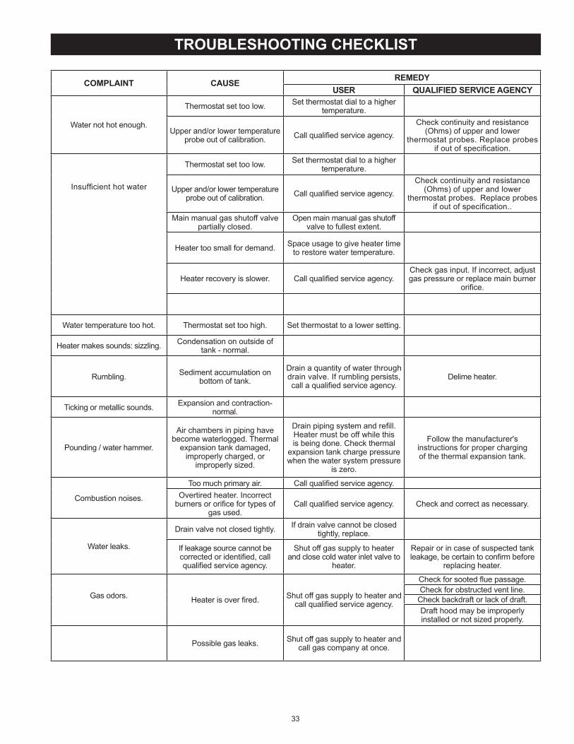
33
COMPLAINT CAUSE REMEDYUSER QUALIFIED SERVICE AGENCY
Water not hot enough
Thermostat set too low Set thermostat dial to a higher temperature
Upper and/or lower temperature probe out of alibration Call quali ed servi e agen y
Che k ontinuity and resistan e (Ohms) of upper and lower
thermostat probes Repla e probes if out of spe i ation
Insuf ient hot water
Thermostat set too low Set thermostat dial to a higher temperature
Upper and/or lower temperature probe out of alibration Call quali ed servi e agen y
Che k ontinuity and resistan e (Ohms) of upper and lower
thermostat probes Repla e probes if out of spe i ation
Main manual gas shutoff valve partially losed
Open main manual gas shutoff valve to fullest extent
Heater too small for demand Spa e usage to give heater time to restore water temperature
Heater re overy is slower Call quali ed servi e agen yChe k gas input If in orre t, adjust gas pressure or repla e main burner
ori e
Water temperature too hot Thermostat set too high Set thermostat to a lower setting
Heater makes sounds sizzling Condensation on outside of tank - normal
Rumbling Sediment a umulation on bottom of tank
Drain a quantity of water through drain valve If rumbling persists,
all a quali ed servi e agen yDelime heater
Ti king or metalli sounds Expansion and ontra tion-normal
Pounding / water hammer
Air hambers in piping have be ome waterlogged Thermal
expansion tank damaged, improperly harged, or
improperly sized
Drain piping system and re ll Heater must be off while this is being done Che k thermal
expansion tank harge pressure when the water system pressure
is zero
Follow the manufa turer sinstru tions for proper hargingof the thermal expansion tank
Combustion noises
Too mu h primary air Call quali ed servi e agen yOvertired heater In orre t
burners or ori e for types of gas used
Call quali ed servi e agen y Che k and orre t as ne essary
Water leaks
Drain valve not losed tightly If drain valve annot be losed tightly, repla e
If leakage sour e annot be orre ted or identi ed, all quali ed servi e agen y
Shut off gas supply to heater and lose old water inlet valve to
heater
Repair or in ase of suspe ted tank leakage, be ertain to on rm before
repla ing heater
Gas odors Heater is over red Shut off gas supply to heater and all quali ed servi e agen y
Che k for sooted ue passageChe k for obstru ted vent line
Che k ba kdraft or la k of draftDraft hood may be improperly installed or not sized properly
Possible gas leaks Shut off gas supply to heater and all gas ompany at on e
TROUBLESHOOTING CHECKLIST

34
A sulfate redu ing ba teria whi h has a umulated within the water heater (this harmless ba teria is nontoxi to humans)
d An ex ess of a tive hydrogen in the tank This is aused by the orrosion prote tive a tion of the anode rod
Smelly water may be eliminated or redu ed in some water heater models by repla ing the anode rod(s) with one of less a tive material, and then hlorinating water heater tank and all water linesConta t the lo al water heater supplier or servi e agen y for further information on erning an Anode Rod Repla ement Kit and this hlorination treatment
If smelly water persists after anode rod repla ement and hlorination treatment, we an only suggest that hlorination or aeration of the water supply be onsidered to eliminate the water problem
Do not remove the anode rod leaving the tank unprote ted By doing so, all warranty on the water heater tank is voided
“AIR” IN HOT WATER FAUCETS
HYDROGEN GAS Hydrogen gas an be produ ed in a hot water system that has not been used for a long period of time (generally two weeks or more) Hydrogen gas is extremely ammable and explosive To prevent the possibility of injury under
these onditions, we re ommend the hot water fau et, lo ated farthest away, be opened for several minutes before any ele tri al applian es whi h are onne ted to the hot water system are used (su h as a dishwasher or washing ma hine) If hydrogen gas is present, there will probably be an unusual sound similar to air es aping through the pipe as the hot water fau et is opened There must be no smoking or open ame near the fau et at the time it is open
HIGH WATER TEMPERATURE SHUT OFF SYSTEMThis water heater is equipped with a manual reset type high limit (Energy Cutout) swit h The high limit swit h interrupts the main burner gas ow should water temperature rea h 203 F (95 C)
In the event of high limit swit h operation, the water heater annot be restarted unless the water temperature is redu ed
to approximately 120F (49C) The high limit reset button on the front of the thermostat then needs to be depressed See Figure 2 for the lo ation of the reset button
START UP CONDITIONS
SMOKE/ODOR
It is not un ommon to experien e a small amount of smoke and odor during the initial start-up This is due to burning off of oil from metal parts, and will disappear in a short while
STRANGE SOUNDS
Possible noises due to expansion and ontra tion of some metal parts during periods of heat-up and ool-down do not ne essarily represent harmful or dangerous onditionsCondensation auses sizzling and popping within the burner area during heating and ooling periods and should be onsidered normal See Condensation" se tion in this manual
CONDENSATION
Whenever the water heater is lled with old water, some ondensate will form while the burner is on A water heater may
appear to be leaking when in fa t the water is ondensation This usually happens whena A new water heater is lled with old water for the rst timeb Burning gas produ es water vapor in water heaters,
parti ularly high ef ien y models where ue temperatures are lower
Large amounts of hot water are used in a short time and the re ll water in the tank is very old
Moisture from the produ ts of ombustion ondense on the ooler tank surfa es and form drops of water whi h may fall onto the burner or other hot surfa es to produ e a sizzling or frying noise
OPERATIONAL CONDITIONS
HOT WATER ODOR
In ea h water heater there is installed at least one anode rod fororrosion prote tion of the tank Certain water onditions will ause a rea tion between this rod and the water The most ommon omplaint asso iated with the anode rod is one of a rotten egg smell in the hot water The smell is a result of four
fa tors whi h must all be present for the odor to developa A on entration of sulfate in the supply waterb Little or no dissolved oxygen in the water
FOR YOUR INFORMATION
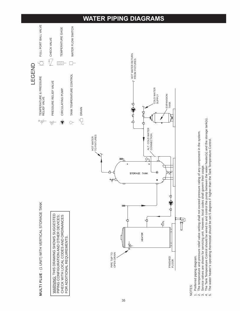
35
WATER PIPING DIAGRAMS
NO
TES
:1.
P
refe
rred
pip
ing
diag
ram
.2.
Th
e te
mpe
ratu
re a
nd p
ress
ure
relie
f val
ve s
ettin
g sh
all n
ot e
xcee
d pr
essu
re ra
ting
of a
ny c
ompo
nent
in th
e sy
stem
.3.
S
ervi
ce v
alve
s ar
e sh
own
for s
ervi
cing
uni
t. H
owev
er, l
ocal
cod
es s
hall
gove
rn th
eir u
sage
.4.
Th
e Ta
nk T
empe
ratu
re C
ontro
l sho
uld
be w
ired
to a
nd c
ontro
l the
pum
p be
twee
n th
e w
ater
hea
ter(
s) a
nd th
e st
orag
e ta
nk(s
).5.
Th
e w
ater
hea
ter’s
ope
ratin
g th
erm
osta
t sho
uld
be s
et 5
deg
rees
F h
ighe
r tha
n th
e Ta
nk T
empe
ratu
re C
ontro
l.
MU
LTI
FLU
E -
(1 U
NIT
) WIT
H V
ER
TIC
AL
STO
RA
GE
TA
NK
LEG
EN
DTE
MP
ER
ATU
RE
& P
RE
SS
UR
ER
ELI
EF
VALV
E
PR
ES
SU
RE
RE
LIE
F VA
LVE
CIR
CU
LATI
NG
PU
MP
TAN
K TE
MPE
RAT
UR
E C
ON
TRO
L
DR
AIN
FULL
PO
RT
BA
LL V
ALV
E
TEM
PE
RAT
UR
E G
AG
E
WAT
ER
FLO
W S
WIT
CH
CH
EC
K V
ALV
EW
AR
NIN
G: T
HIS
DR
AWIN
G S
HO
WS
SU
GG
ES
TED
PIP
ING
CO
NFI
GU
RAT
ION
AN
D O
THE
R D
EV
ICE
S;
CH
EC
K W
ITH
LO
CA
L C
OD
ES
AN
D O
RD
INA
NC
ES
FOR
AD
DIT
ION
AL
RE
QU
IRE
ME
NTS
.
FIN
ISH
ED
FLO
OR
HO
T W
ATE
RTO
FIX
TUR
ES
CO
LD W
ATE
RS
UP
PLY
EX
PA
NS
ION
TAN
K
ALT
. CO
LD W
ATE
RC
ON
NE
CTI
ON
HO
T W
ATE
R R
ETU
RN
FRO
M F
IXTU
RE
S
PIP
E T
&P
TO
OP
EN
DR
AIN

36
NO
TES
:1.
P
refe
rred
pip
ing
diag
ram
.2.
Th
e te
mpe
ratu
re a
nd p
ress
ure
relie
f val
ve s
ettin
g sh
all n
ot e
xcee
d pr
essu
re ra
ting
of a
ny c
ompo
nent
in th
e sy
stem
.3.
S
ervi
ce v
alve
s ar
e sh
own
for s
ervi
cing
uni
t. H
owev
er, l
ocal
cod
es s
hall
gove
rn th
eir u
sage
.4.
Th
e Ta
nk T
empe
ratu
re C
ontro
l sho
uld
be w
ired
to a
nd c
ontro
l the
pum
p be
twee
n th
e w
ater
hea
ter(
s) a
nd th
e st
orag
e ta
nk(s
).5.
Th
e w
ater
hea
ter’s
ope
ratin
g th
erm
osta
t sho
uld
be s
et 5
deg
rees
F h
ighe
r tha
n th
e Ta
nk T
empe
ratu
re C
ontro
l.
MU
LTI
FLU
E -
(1 U
NIT
) WIT
H H
OR
IZO
NTA
L S
TOR
AG
E T
AN
K
LEG
EN
DTE
MP
ER
ATU
RE
& P
RE
SS
UR
ER
ELI
EF
VALV
E
PR
ES
SU
RE
RE
LIE
F VA
LVE
CIR
CU
LATI
NG
PU
MP
TAN
K TE
MPE
RAT
UR
E C
ON
TRO
L
DR
AIN
FULL
PO
RT
BA
LL V
ALV
E
TEM
PE
RAT
UR
E G
AG
E
WAT
ER
FLO
W S
WIT
CH
CH
EC
K V
ALV
EW
AR
NIN
G: T
HIS
DR
AWIN
G S
HO
WS
SU
GG
ES
TED
PIP
ING
CO
NFI
GU
RAT
ION
AN
D O
THE
R D
EV
ICE
S;
CH
EC
K W
ITH
LO
CA
L C
OD
ES
AN
D O
RD
INA
NC
ES
FOR
AD
DIT
ION
AL
RE
QU
IRE
ME
NTS
.
FIN
ISH
ED
FLO
OR
HO
T W
ATE
R T
O F
IXTU
RE
S
CO
LD W
ATE
RS
UP
PLY
HO
T W
ATE
RR
ETU
RN
FR
OM
FI
XTU
RE
SA
LTE
RN
ATE
LOC
ATI
ON
CIR
CU
LATI
NG
PU
MP
EX
PA
NS
ION
TAN
K
PIP
E T
&P
TO
OP
EN
DR
AIN

37
NO
TES
:1.
P
refe
rred
pip
ing
diag
ram
.2.
Th
e te
mpe
ratu
re a
nd p
ress
ure
relie
f val
ve s
ettin
g sh
all n
ot e
xcee
d pr
essu
re ra
ting
of a
ny c
ompo
nent
in th
e sy
stem
.3.
S
ervi
ce v
alve
s ar
e sh
own
for s
ervi
cing
uni
t. H
owev
er, l
ocal
cod
es s
hall
gove
rn th
eir u
sage
.4.
Th
e Ta
nk T
empe
ratu
re C
ontro
l sho
uld
be w
ired
to a
nd c
ontro
l the
pum
p be
twee
n th
e w
ater
hea
ter(
s) a
nd th
e st
orag
e ta
nk(s
).
MU
LTI
FLU
E -
(1 U
NIT
) WIT
H M
IXIN
G V
ALV
E T
WO
TE
MP
ER
ATU
RE
LEG
EN
DTE
MP
ER
ATU
RE
& P
RE
SS
UR
ER
ELI
EF
VALV
E
PR
ES
SU
RE
RE
LIE
F VA
LVE
CIR
CU
LATI
NG
PU
MP
TAN
K TE
MPE
RAT
UR
E C
ON
TRO
L
DR
AIN
FULL
PO
RT
BA
LL V
ALV
E
TEM
PE
RAT
UR
E G
AG
E
WAT
ER
FLO
W S
WIT
CH
CH
EC
K V
ALV
EW
AR
NIN
G: T
HIS
DR
AWIN
G S
HO
WS
SU
GG
ES
TED
PIP
ING
CO
NFI
GU
RAT
ION
AN
D O
THE
R D
EV
ICE
S;
CH
EC
K W
ITH
LO
CA
L C
OD
ES
AN
D O
RD
INA
NC
ES
FOR
AD
DIT
ION
AL
RE
QU
IRE
ME
NTS
.
TEM
PE
RE
DW
ATE
RR
ETU
RN
TEM
PE
RE
DW
ATE
RO
UTL
ET
HO
TW
ATE
RO
UTL
ET
HO
TW
ATE
RR
ETU
RN
CO
LD W
ATE
RS
UP
PLY
CO
LD
HO
T
EX
PA
NS
ION
TAN
K
PIP
E T
&P
TO
OP
EN
DR
AIN

38
NO
TES
:1.
P
refe
rred
pip
ing
diag
ram
.2.
Th
e te
mpe
ratu
re a
nd p
ress
ure
relie
f val
ve s
ettin
g sh
all n
ot e
xcee
d pr
essu
re ra
ting
of a
ny c
ompo
nent
in th
e sy
stem
.3.
S
ervi
ce v
alve
s ar
e sh
own
for s
ervi
cing
uni
t. H
owev
er, l
ocal
cod
es s
hall
gove
rn th
eir u
sage
.4.
Th
e Ta
nk T
empe
ratu
re C
ontro
l sho
uld
be w
ired
to a
nd c
ontro
l the
pum
p be
twee
n th
e w
ater
hea
ter(
s) a
nd th
e st
orag
e ta
nk(s
).
MU
LTI
FLU
E -
(2 U
NIT
S)
LEG
EN
DTE
MP
ER
ATU
RE
& P
RE
SS
UR
ER
ELI
EF
VALV
E
PR
ES
SU
RE
RE
LIE
F VA
LVE
CIR
CU
LATI
NG
PU
MP
TAN
K TE
MPE
RAT
UR
E C
ON
TRO
L
DR
AIN
FULL
PO
RT
BA
LL V
ALV
E
TEM
PE
RAT
UR
E G
AG
E
WAT
ER
FLO
W S
WIT
CH
CH
EC
K V
ALV
EW
AR
NIN
G: T
HIS
DR
AWIN
G S
HO
WS
SU
GG
ES
TED
PIP
ING
CO
NFI
GU
RAT
ION
AN
D O
THE
R D
EV
ICE
S;
CH
EC
K W
ITH
LO
CA
L C
OD
ES
AN
D O
RD
INA
NC
ES
FOR
AD
DIT
ION
AL
RE
QU
IRE
ME
NTS
.
HO
T W
ATE
RTO
FIX
TUR
ES
CO
LD W
ATE
RS
UP
PLY
HO
T W
ATE
RR
ETU
RN
EX
PA
NS
ION
TAN
K
PIP
E T
&P
TO
OP
EN
DR
AIN
PIP
E T
&P
TO
OP
EN
DR
AIN
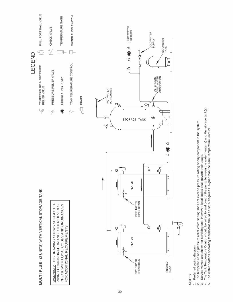
39
NO
TES
:1.
P
refe
rred
pip
ing
diag
ram
.2.
Th
e te
mpe
ratu
re a
nd p
ress
ure
relie
f val
ve s
ettin
g sh
all n
ot e
xcee
d pr
essu
re ra
ting
of a
ny c
ompo
nent
in th
e sy
stem
.3.
S
ervi
ce v
alve
s ar
e sh
own
for s
ervi
cing
uni
t. H
owev
er, l
ocal
cod
es s
hall
gove
rn th
eir u
sage
.4.
Th
e Ta
nk T
empe
ratu
re C
ontro
l sho
uld
be w
ired
to a
nd c
ontro
l the
pum
p be
twee
n th
e w
ater
hea
ter(
s) a
nd th
e st
orag
e ta
nk(s
).5.
Th
e w
ater
hea
ter’s
ope
ratin
g th
erm
osta
t sho
uld
be s
et 5
deg
rees
F h
ighe
r tha
n th
e Ta
nk T
empe
ratu
re C
ontro
l.
MU
LTI
FLU
E -
(2 U
NIT
S) W
ITH
VE
RTI
CA
L S
TOR
AG
E T
AN
K
LEG
EN
DTE
MP
ER
ATU
RE
& P
RE
SS
UR
ER
ELI
EF
VALV
E
PR
ES
SU
RE
RE
LIE
F VA
LVE
CIR
CU
LATI
NG
PU
MP
TAN
K TE
MPE
RAT
UR
E C
ON
TRO
L
DR
AIN
FULL
PO
RT
BA
LL V
ALV
E
TEM
PE
RAT
UR
E G
AG
E
WAT
ER
FLO
W S
WIT
CH
CH
EC
K V
ALV
EW
AR
NIN
G: T
HIS
DR
AWIN
G S
HO
WS
SU
GG
ES
TED
PIP
ING
CO
NFI
GU
RAT
ION
AN
D O
THE
R D
EV
ICE
S;
CH
EC
K W
ITH
LO
CA
L C
OD
ES
AN
D O
RD
INA
NC
ES
FOR
AD
DIT
ION
AL
RE
QU
IRE
ME
NTS
.
FIN
ISH
ED
FLO
OR
CO
LD W
ATE
RS
UP
PLY
HO
T W
ATE
RTO
FIX
TUR
ES
ALT
ER
NA
TEC
OLD
WA
TER
CO
NN
EC
TIO
N
HO
T W
ATE
RR
ETU
RN
EX
PA
NS
ION
TAN
K
PIP
E T
&P
TO
OP
EN
DR
AIN
PIP
E T
&P
TO
OP
EN
DR
AIN
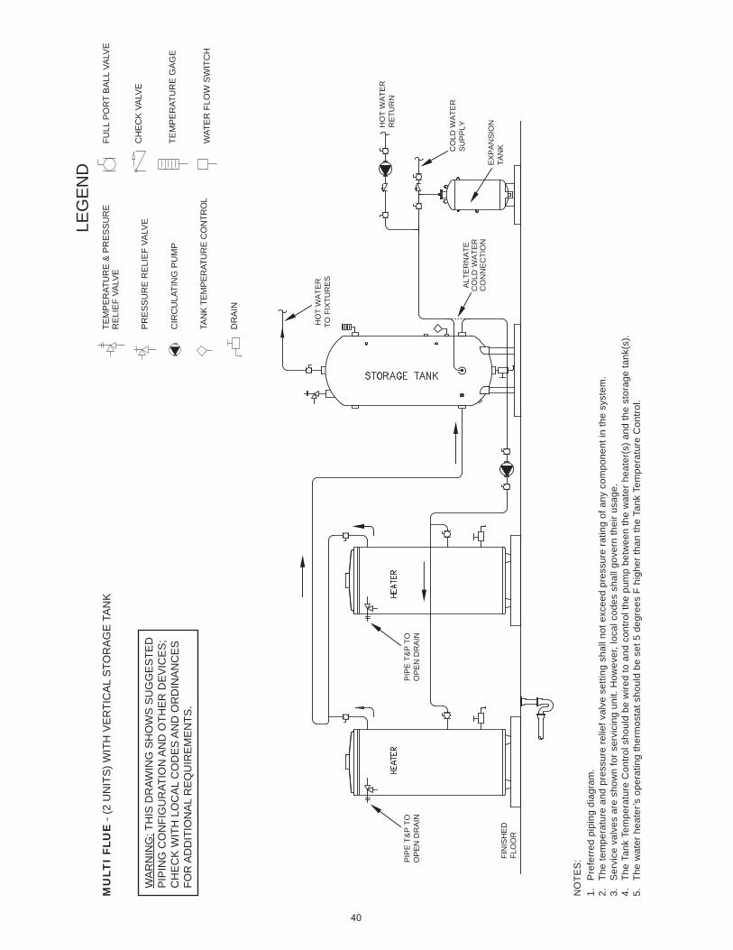
40
NO
TES
:1.
P
refe
rred
pip
ing
diag
ram
.2.
Th
e te
mpe
ratu
re a
nd p
ress
ure
relie
f val
ve s
ettin
g sh
all n
ot e
xcee
d pr
essu
re ra
ting
of a
ny c
ompo
nent
in th
e sy
stem
.3.
S
ervi
ce v
alve
s ar
e sh
own
for s
ervi
cing
uni
t. H
owev
er, l
ocal
cod
es s
hall
gove
rn th
eir u
sage
.4.
Th
e Ta
nk T
empe
ratu
re C
ontro
l sho
uld
be w
ired
to a
nd c
ontro
l the
pum
p be
twee
n th
e w
ater
hea
ter(
s) a
nd th
e st
orag
e ta
nk(s
).5.
Th
e w
ater
hea
ter’s
ope
ratin
g th
erm
osta
t sho
uld
be s
et 5
deg
rees
F h
ighe
r tha
n th
e Ta
nk T
empe
ratu
re C
ontro
l.
MU
LTI
FLU
E -
(2 U
NIT
S) W
ITH
VE
RTI
CA
L S
TOR
AG
E T
AN
K
LEG
EN
DTE
MP
ER
ATU
RE
& P
RE
SS
UR
ER
ELI
EF
VALV
E
PR
ES
SU
RE
RE
LIE
F VA
LVE
CIR
CU
LATI
NG
PU
MP
TAN
K TE
MPE
RAT
UR
E C
ON
TRO
L
DR
AIN
FULL
PO
RT
BA
LL V
ALV
E
TEM
PE
RAT
UR
E G
AG
E
WAT
ER
FLO
W S
WIT
CH
CH
EC
K V
ALV
EW
AR
NIN
G: T
HIS
DR
AWIN
G S
HO
WS
SU
GG
ES
TED
PIP
ING
CO
NFI
GU
RAT
ION
AN
D O
THE
R D
EV
ICE
S;
CH
EC
K W
ITH
LO
CA
L C
OD
ES
AN
D O
RD
INA
NC
ES
FOR
AD
DIT
ION
AL
RE
QU
IRE
ME
NTS
.
FIN
ISH
ED
FLO
OR
CO
LD W
ATE
RS
UP
PLY
HO
T W
ATE
RTO
FIX
TUR
ES
ALT
ER
NA
TEC
OLD
WA
TER
CO
NN
EC
TIO
N
HO
T W
ATE
RR
ETU
RN
EX
PA
NS
ION
TAN
K
PIP
E T
&P
TO
OP
EN
DR
AIN
PIP
E T
&P
TO
OP
EN
DR
AIN
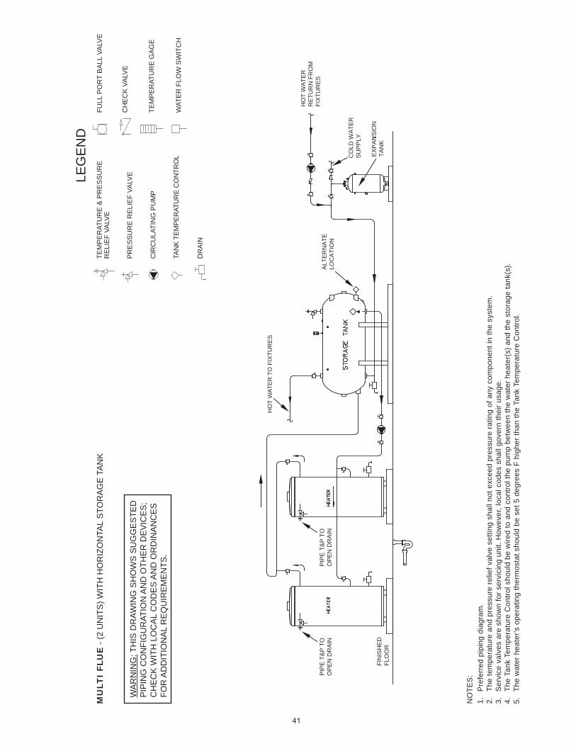
41
NO
TES
:1.
P
refe
rred
pip
ing
diag
ram
.2.
Th
e te
mpe
ratu
re a
nd p
ress
ure
relie
f val
ve s
ettin
g sh
all n
ot e
xcee
d pr
essu
re ra
ting
of a
ny c
ompo
nent
in th
e sy
stem
.3.
S
ervi
ce v
alve
s ar
e sh
own
for s
ervi
cing
uni
t. H
owev
er, l
ocal
cod
es s
hall
gove
rn th
eir u
sage
.4.
Th
e Ta
nk T
empe
ratu
re C
ontro
l sho
uld
be w
ired
to a
nd c
ontro
l the
pum
p be
twee
n th
e w
ater
hea
ter(
s) a
nd th
e st
orag
e ta
nk(s
).5.
Th
e w
ater
hea
ter’s
ope
ratin
g th
erm
osta
t sho
uld
be s
et 5
deg
rees
F h
ighe
r tha
n th
e Ta
nk T
empe
ratu
re C
ontro
l.
MU
LTI
FLU
E -
(2 U
NIT
S) W
ITH
HO
RIZ
ON
TAL
STO
RA
GE
TA
NK
LEG
EN
DTE
MP
ER
ATU
RE
& P
RE
SS
UR
ER
ELI
EF
VALV
E
PR
ES
SU
RE
RE
LIE
F VA
LVE
CIR
CU
LATI
NG
PU
MP
TAN
K TE
MPE
RAT
UR
E C
ON
TRO
L
DR
AIN
FULL
PO
RT
BA
LL V
ALV
E
TEM
PE
RAT
UR
E G
AG
E
WAT
ER
FLO
W S
WIT
CH
CH
EC
K V
ALV
EW
AR
NIN
G: T
HIS
DR
AWIN
G S
HO
WS
SU
GG
ES
TED
PIP
ING
CO
NFI
GU
RAT
ION
AN
D O
THE
R D
EV
ICE
S;
CH
EC
K W
ITH
LO
CA
L C
OD
ES
AN
D O
RD
INA
NC
ES
FOR
AD
DIT
ION
AL
RE
QU
IRE
ME
NTS
.
FIN
ISH
ED
FLO
OR
HO
T W
ATE
R T
O F
IXTU
RE
S
CO
LD W
ATE
RS
UP
PLY
HO
T W
ATE
RR
ETU
RN
FR
OM
FI
XTU
RE
SA
LTE
RN
ATE
LOC
ATI
ON
EX
PA
NS
ION
TAN
K
PIP
E T
&P
TO
OP
EN
DR
AIN
PIP
E T
&P
TO
OP
EN
DR
AIN

42
NO
TES
:1.
P
refe
rred
pip
ing
diag
ram
.2.
Th
e te
mpe
ratu
re a
nd p
ress
ure
relie
f val
ve s
ettin
g sh
all n
ot e
xcee
d pr
essu
re ra
ting
of a
ny c
ompo
nent
in th
e sy
stem
.3.
S
ervi
ce v
alve
s ar
e sh
own
for s
ervi
cing
uni
t. H
owev
er, l
ocal
cod
es s
hall
gove
rn th
eir u
sage
.
MU
LTI F
LUE
(2 U
NIT
S) T
WO
TEM
PER
ATU
RE
LEG
EN
DTE
MP
ER
ATU
RE
& P
RE
SS
UR
ER
ELI
EF
VALV
E
PR
ES
SU
RE
RE
LIE
F VA
LVE
CIR
CU
LATI
NG
PU
MP
TAN
K TE
MPE
RAT
UR
E C
ON
TRO
L
DR
AIN
FULL
PO
RT
BA
LL V
ALV
E
TEM
PE
RAT
UR
E G
AG
E
WAT
ER
FLO
W S
WIT
CH
CH
EC
K V
ALV
EW
AR
NIN
G: T
HIS
DR
AWIN
G S
HO
WS
SU
GG
ES
TED
PIP
ING
CO
NFI
GU
RAT
ION
AN
D O
THE
R D
EV
ICE
S;
CH
EC
K W
ITH
LO
CA
L C
OD
ES
AN
D O
RD
INA
NC
ES
FOR
AD
DIT
ION
AL
RE
QU
IRE
ME
NTS
.
BO
OS
TER
WA
TER
RE
TUR
N
PR
E-H
EA
TED
WA
TER
TO
B
OO
STE
R
BO
OS
TER
WA
TER
TO F
IXTU
RE
SH
OT
WA
TER
TO F
IXTU
RE
S
EX
PA
NS
ION
TA
NK
HO
T W
ATE
RR
ETU
RN
CO
LD W
ATE
RS
UP
PLY
1st H
EA
TER
BO
OS
TER
HE
ATE
R

43
NO
TES
:1.
P
refe
rred
pip
ing
diag
ram
.2.
Th
e te
mpe
ratu
re a
nd p
ress
ure
relie
f val
ve s
ettin
g sh
all n
ot e
xcee
d pr
essu
re ra
ting
of a
ny c
ompo
nent
in th
e sy
stem
.3.
S
ervi
ce v
alve
s ar
e sh
own
for s
ervi
cing
uni
t. H
owev
er, l
ocal
cod
es s
hall
gove
rn th
eir u
sage
.
MU
LTI
FLU
E (
2 U
NIT
S)
WIT
H B
OO
ST
ER
TW
O T
EM
PE
RA
TU
RE
LEG
EN
DTE
MP
ER
ATU
RE
& P
RE
SS
UR
ER
ELI
EF
VALV
E
PR
ES
SU
RE
RE
LIE
F VA
LVE
CIR
CU
LATI
NG
PU
MP
TAN
K TE
MPE
RAT
UR
E C
ON
TRO
L
DR
AIN
FULL
PO
RT
BA
LL V
ALV
E
TEM
PE
RAT
UR
E G
AG
E
WAT
ER
FLO
W S
WIT
CH
CH
EC
K V
ALV
EW
AR
NIN
G: T
HIS
DR
AWIN
G S
HO
WS
SU
GG
ES
TED
PIP
ING
CO
NFI
GU
RAT
ION
AN
D O
THE
R D
EV
ICE
S;
CH
EC
K W
ITH
LO
CA
L C
OD
ES
AN
D O
RD
INA
NC
ES
FOR
AD
DIT
ION
AL
RE
QU
IRE
ME
NTS
.
EX
PA
NS
ION
TAN
K
BO
OS
TED
WA
TER
OU
TLE
T
TYP
ICA
LB
OO
STE
RH
EA
TER
PR
E-H
EA
TER
PR
E-H
EA
TER
MU
ST
BE
IDE
NTI
CA
L H
EA
TER
S
FIN
ISH
ED
FLO
OR
CO
LD W
ATE
RS
UP
PLY
HO
T O
UTL
ET
AT
STO
RE
DTE
MP
ER
ATU
RE
BO
OS
TER
RE
TUR
N(IF
US
ED
)
HO
T W
ATE
RR
ETU
RN
PIP
E T
&P
TO
OP
EN
DR
AIN
PIP
E T
&P
TO
OP
EN
DR
AIN
PIP
E T
&P
TO
OP
EN
DR
AIN

44
NO
TES
:1.
P
refe
rred
pip
ing
diag
ram
.2.
Th
e te
mpe
ratu
re a
nd p
ress
ure
relie
f val
ve s
ettin
g sh
all n
ot e
xcee
d pr
essu
re ra
ting
of a
ny c
ompo
nent
in th
e sy
stem
.3.
S
ervi
ce v
alve
s ar
e sh
own
for s
ervi
cing
uni
t. H
owev
er, l
ocal
cod
es s
hall
gove
rn th
eir u
sage
.
MU
LTI-
FLU
E (
3 U
NIT
S)
LEG
EN
DTE
MP
ER
ATU
RE
& P
RE
SS
UR
ER
ELI
EF
VALV
E
PR
ES
SU
RE
RE
LIE
F VA
LVE
CIR
CU
LATI
NG
PU
MP
TAN
K TE
MPE
RAT
UR
E C
ON
TRO
L
DR
AIN
FULL
PO
RT
BA
LL V
ALV
E
TEM
PE
RAT
UR
E G
AG
E
WAT
ER
FLO
W S
WIT
CH
CH
EC
K V
ALV
EW
AR
NIN
G: T
HIS
DR
AWIN
G S
HO
WS
SU
GG
ES
TED
PIP
ING
CO
NFI
GU
RAT
ION
AN
D O
THE
R D
EV
ICE
S;
CH
EC
K W
ITH
LO
CA
L C
OD
ES
AN
D O
RD
INA
NC
ES
FOR
AD
DIT
ION
AL
RE
QU
IRE
ME
NTS
.
HO
T W
ATE
RTO
FIX
TUR
ES
HO
T W
ATE
RR
ETU
RN
CO
LD W
ATE
RS
UP
PLY
EX
PA
NS
ION
TAN
K
PIP
E T
&P
TO
OP
EN
DR
AIN
PIP
E T
&P
TO
OP
EN
DR
AIN
PIP
E T
&P
TO
OP
EN
DR
AIN

45
NO
TES
:1.
P
refe
rred
pip
ing
diag
ram
.2.
Th
e te
mpe
ratu
re a
nd p
ress
ure
relie
f val
ve s
ettin
g sh
all n
ot e
xcee
d pr
essu
re ra
ting
of a
ny c
ompo
nent
in th
e sy
stem
.3.
S
ervi
ce v
alve
s ar
e sh
own
for s
ervi
cing
uni
t. H
owev
er, l
ocal
cod
es s
hall
gove
rn th
eir u
sage
.4.
Th
e Ta
nk T
empe
ratu
re C
ontro
l sho
uld
be w
ired
to a
nd c
ontro
l the
pum
p be
twee
n th
e w
ater
hea
ter(
s) a
nd th
e st
orag
e ta
nk(s
).5.
Th
e w
ater
hea
ter’s
ope
ratin
g th
erm
osta
t sho
uld
be s
et 5
deg
rees
F h
ighe
r tha
n th
e Ta
nk T
empe
ratu
re C
ontro
l.
MU
LTI-
FLU
E (
3 U
NIT
S)
WIT
H V
ER
TIC
AL
STO
RA
GE
TA
NK
LEG
EN
DTE
MP
ER
ATU
RE
& P
RE
SS
UR
ER
ELI
EF
VALV
E
PR
ES
SU
RE
RE
LIE
F VA
LVE
CIR
CU
LATI
NG
PU
MP
TAN
K TE
MPE
RAT
UR
E C
ON
TRO
L
DR
AIN
FULL
PO
RT
BA
LL V
ALV
E
TEM
PE
RAT
UR
E G
AG
E
WAT
ER
FLO
W S
WIT
CH
CH
EC
K V
ALV
EW
AR
NIN
G: T
HIS
DR
AWIN
G S
HO
WS
SU
GG
ES
TED
PIP
ING
CO
NFI
GU
RAT
ION
AN
D O
THE
R D
EV
ICE
S;
CH
EC
K W
ITH
LO
CA
L C
OD
ES
AN
D O
RD
INA
NC
ES
FOR
AD
DIT
ION
AL
RE
QU
IRE
ME
NTS
.
TO F
IXTU
RE
S
HO
T W
ATE
RR
ETU
RN
ALT
. CO
LD W
ATE
RC
ON
NE
CTI
ON
AOSSTORAGE TANK
HO
T W
ATE
R
HE
ATE
RH
EA
TER
HE
ATE
R
FIN
ISH
ED
FLO
OR
CO
LD W
ATE
RS
UP
PLY
EX
PA
NS
ION
TA
NK
PIP
E T
&P
TO
OP
EN
DR
AIN
PIP
E T
&P
TO
OP
EN
DR
AIN
PIP
E T
&P
TO
OP
EN
DR
AIN
PIP
E T
&P
TO
OP
EN
DR
AIN

46
NO
TES
:1.
P
refe
rred
pip
ing
diag
ram
.2.
Th
e te
mpe
ratu
re a
nd p
ress
ure
relie
f val
ve s
ettin
g sh
all n
ot e
xcee
d pr
essu
re ra
ting
of a
ny c
ompo
nent
in th
e sy
stem
.3.
S
ervi
ce v
alve
s ar
e sh
own
for s
ervi
cing
uni
t. H
owev
er, l
ocal
cod
es s
hall
gove
rn th
eir u
sage
.4.
Th
e Ta
nk T
empe
ratu
re C
ontro
l sho
uld
be w
ired
to a
nd c
ontro
l the
pum
p be
twee
n th
e w
ater
hea
ter(
s) a
nd th
e st
orag
e ta
nk(s
).5.
Th
e w
ater
hea
ter’s
ope
ratin
g th
erm
osta
t sho
uld
be s
et 5
deg
rees
F h
ighe
r tha
n th
e Ta
nk T
empe
ratu
re C
ontro
l.
MU
LTI-
FLU
E (
3 U
NIT
S)
WIT
H H
OR
IZO
NTA
L S
TOR
AG
E T
AN
K
LEG
EN
DTE
MP
ER
ATU
RE
& P
RE
SS
UR
ER
ELI
EF
VALV
E
PR
ES
SU
RE
RE
LIE
F VA
LVE
CIR
CU
LATI
NG
PU
MP
TAN
K TE
MPE
RAT
UR
E C
ON
TRO
L
DR
AIN
FULL
PO
RT
BA
LL V
ALV
E
TEM
PE
RAT
UR
E G
AG
E
WAT
ER
FLO
W S
WIT
CH
CH
EC
K V
ALV
EW
AR
NIN
G: T
HIS
DR
AWIN
G S
HO
WS
SU
GG
ES
TED
PIP
ING
CO
NFI
GU
RAT
ION
AN
D O
THE
R D
EV
ICE
S;
CH
EC
K W
ITH
LO
CA
L C
OD
ES
AN
D O
RD
INA
NC
ES
FOR
AD
DIT
ION
AL
RE
QU
IRE
ME
NTS
.
HO
T W
ATE
RR
ETU
RN
ALT
ER
NA
TELO
CA
TIO
N
HO
T W
ATE
R T
O F
IXTU
RE
S
AO
SS
TOR
AG
E T
AN
K
HE
ATE
RH
EA
TER
HE
ATE
R
FIN
ISH
ED
FLO
OR
EX
PA
NS
ION
TA
NK
CO
LD W
ATE
RS
UP
PLY
PIP
E T
&P
TO
OP
EN
DR
AIN
PIP
E T
&P
TO
OP
EN
DR
AIN
PIP
E T
&P
TO
OP
EN
DR
AIN
PIP
E T
&P
TO
OP
EN
DR
AIN

47
NO
TES
:1.
P
refe
rred
pip
ing
diag
ram
.2.
Th
e te
mpe
ratu
re a
nd p
ress
ure
relie
f val
ve s
ettin
g sh
all n
ot e
xcee
d pr
essu
re ra
ting
of a
ny c
ompo
nent
in th
e sy
stem
.3.
S
ervi
ce v
alve
s ar
e sh
own
for s
ervi
cing
uni
t. H
owev
er, l
ocal
cod
es s
hall
gove
rn th
eir u
sage
.
MU
LTI
FLU
E F
LUE
(4
UN
ITS
)
LEG
EN
DTE
MP
ER
ATU
RE
& P
RE
SS
UR
ER
ELI
EF
VALV
E
PR
ES
SU
RE
RE
LIE
F VA
LVE
CIR
CU
LATI
NG
PU
MP
TAN
K TE
MPE
RAT
UR
E C
ON
TRO
L
DR
AIN
FULL
PO
RT
BA
LL V
ALV
E
TEM
PE
RAT
UR
E G
AG
E
WAT
ER
FLO
W S
WIT
CH
CH
EC
K V
ALV
EW
AR
NIN
G: T
HIS
DR
AWIN
G S
HO
WS
SU
GG
ES
TED
PIP
ING
CO
NFI
GU
RAT
ION
AN
D O
THE
R D
EV
ICE
S;
CH
EC
K W
ITH
LO
CA
L C
OD
ES
AN
D O
RD
INA
NC
ES
FOR
AD
DIT
ION
AL
RE
QU
IRE
ME
NTS
.
EX
PA
NS
ION
TAN
K
CO
LD W
ATE
RS
UP
PLY
HO
T W
ATE
RTO
FIX
TUR
ES
FIN
ISH
ED
FLO
OR
HO
T W
ATE
RR
ETU
RN
PIP
E T
&P
TO
OP
EN
DR
AIN
PIP
E T
&P
TO
OP
EN
DR
AIN
PIP
E T
&P
TO
OP
EN
DR
AIN
PIP
E T
&P
TO
OP
EN
DR
AIN

48
NO
TES
:1.
P
refe
rred
pip
ing
diag
ram
.2.
Th
e te
mpe
ratu
re a
nd p
ress
ure
relie
f val
ve s
ettin
g sh
all n
ot e
xcee
d pr
essu
re ra
ting
of a
ny c
ompo
nent
in th
e sy
stem
.3.
S
ervi
ce v
alve
s ar
e sh
own
for s
ervi
cing
uni
t. H
owev
er, l
ocal
cod
es s
hall
gove
rn th
eir u
sage
.4.
Th
e Ta
nk T
empe
ratu
re C
ontro
l sho
uld
be w
ired
to a
nd c
ontro
l the
pum
p be
twee
n th
e w
ater
hea
ter(
s) a
nd th
e st
orag
e ta
nk(s
).5.
Th
e w
ater
hea
ter’s
ope
ratin
g th
erm
osta
t sho
uld
be s
et 5
deg
rees
F h
ighe
r tha
n th
e Ta
nk T
empe
ratu
re C
ontro
l.
MU
LTI-
FLU
E (
4 U
NIT
S)
WIT
H V
ER
TIC
AL
STO
RA
GE
TA
NK
LEG
EN
DTE
MP
ER
ATU
RE
& P
RE
SS
UR
ER
ELI
EF
VALV
E
PR
ES
SU
RE
RE
LIE
F VA
LVE
CIR
CU
LATI
NG
PU
MP
TAN
K TE
MPE
RAT
UR
E C
ON
TRO
L
DR
AIN
FULL
PO
RT
BA
LL V
ALV
E
TEM
PE
RAT
UR
E G
AG
E
WAT
ER
FLO
W S
WIT
CH
CH
EC
K V
ALV
EW
AR
NIN
G: T
HIS
DR
AWIN
G S
HO
WS
SU
GG
ES
TED
PIP
ING
CO
NFI
GU
RAT
ION
AN
D O
THE
R D
EV
ICE
S;
CH
EC
K W
ITH
LO
CA
L C
OD
ES
AN
D O
RD
INA
NC
ES
FOR
AD
DIT
ION
AL
RE
QU
IRE
ME
NTS
.
HO
T W
ATE
RTO
FIX
TUR
ES
HO
T W
ATE
RR
ETU
RN
CO
LD W
ATE
RS
UP
PLY
EX
PA
NS
ION
TAN
K
ALT
. CO
LDW
ATE
RC
ON
NE
CTI
ON
AOSSTORAGE TANK
HE
ATE
RH
EA
TER
HE
ATE
RH
EA
TER
FIN
ISH
ED
FLO
OR
PIP
E T
&P
TO
OP
EN
DR
AIN
PIP
E T
&P
TO
OP
EN
DR
AIN
PIP
E T
&P
TO
OP
EN
DR
AIN
PIP
E T
&P
TO
OP
EN
DR
AIN
PIP
E T
&P
TO
OP
EN
DR
AIN

49
NO
TES
:1.
P
refe
rred
pip
ing
diag
ram
.2.
Th
e te
mpe
ratu
re a
nd p
ress
ure
relie
f val
ve s
ettin
g sh
all n
ot e
xcee
d pr
essu
re ra
ting
of a
ny c
ompo
nent
in th
e sy
stem
.3.
S
ervi
ce v
alve
s ar
e sh
own
for s
ervi
cing
uni
t. H
owev
er, l
ocal
cod
es s
hall
gove
rn th
eir u
sage
.4.
Th
e Ta
nk T
empe
ratu
re C
ontro
l sho
uld
be w
ired
to a
nd c
ontro
l the
pum
p be
twee
n th
e w
ater
hea
ter(
s) a
nd th
e st
orag
e ta
nk(s
).5.
Th
e w
ater
hea
ter’s
ope
ratin
g th
erm
osta
t sho
uld
be s
et 5
deg
rees
F h
ighe
r tha
n th
e Ta
nk T
empe
ratu
re C
ontro
l.
MU
LTI-
FLU
E (
4 U
NIT
S)
WIT
H H
OR
IZO
NTA
L S
TOR
AG
E T
AN
K
LEG
EN
DTE
MP
ER
ATU
RE
& P
RE
SS
UR
ER
ELI
EF
VALV
E
PR
ES
SU
RE
RE
LIE
F VA
LVE
CIR
CU
LATI
NG
PU
MP
TAN
K TE
MPE
RAT
UR
E C
ON
TRO
L
DR
AIN
FULL
PO
RT
BA
LL V
ALV
E
TEM
PE
RAT
UR
E G
AG
E
WAT
ER
FLO
W S
WIT
CH
CH
EC
K V
ALV
EW
AR
NIN
G: T
HIS
DR
AWIN
G S
HO
WS
SU
GG
ES
TED
PIP
ING
CO
NFI
GU
RAT
ION
AN
D O
THE
R D
EV
ICE
S;
CH
EC
K W
ITH
LO
CA
L C
OD
ES
AN
D O
RD
INA
NC
ES
FOR
AD
DIT
ION
AL
RE
QU
IRE
ME
NTS
.
HO
T W
ATE
RTO
FIX
TUR
ES
HO
T W
ATE
RR
ETU
RN
CO
LD W
ATE
RS
UP
PLY
ALT
ER
NA
TELO
CA
TIO
NA
OS
STO
RA
GE
TA
NK
HE
ATE
RH
EA
TER
HE
ATE
RH
EA
TER
FIN
ISH
ED
FLO
OR
EX
PA
NS
ION
TA
NK
PIP
E T
&P
TO
OP
EN
DR
AIN
PIP
E T
&P
TO
OP
EN
DR
AIN
PIP
E T
&P
TO
OP
EN
DR
AIN
PIP
E T
&P
TO
OP
EN
DR
AIN
PIP
E T
&P
TO
OP
EN
DR
AIN
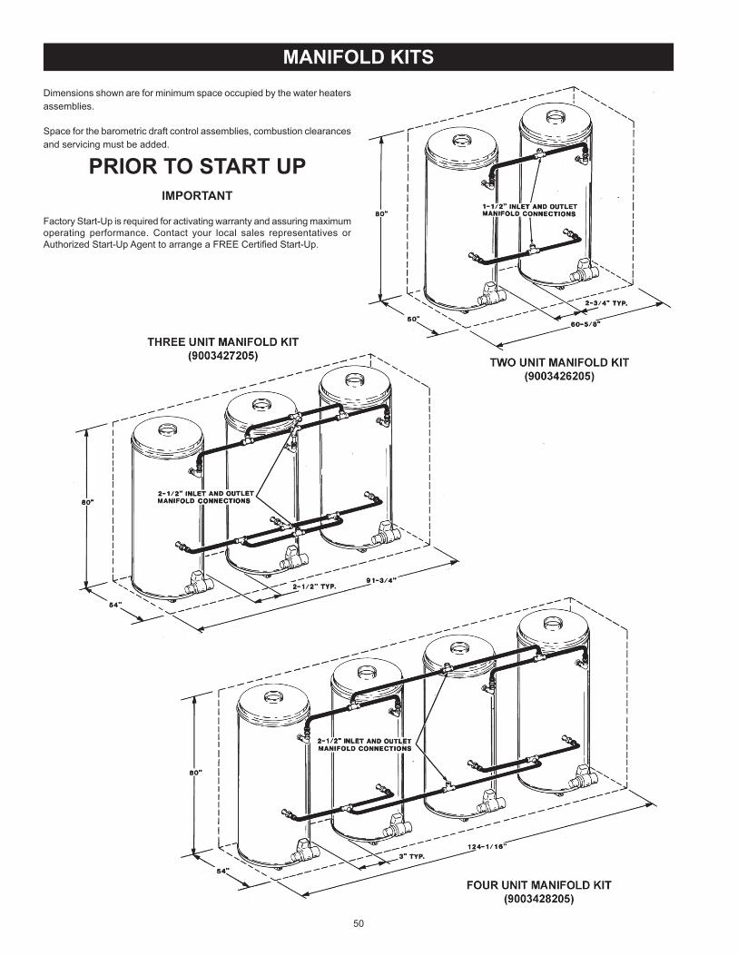
50
MANIFOLD KITSDimensions shown are for minimum spa e o upied by the water heaters assemblies
Spa e for the barometri draft ontrol assemblies, ombustion learan es and servi ing must be added
PRIOR TO START UPIMPORTANT
Fa tory Start-Up is required for a tivating warranty and assuring maximum operating performan e Conta t your lo al sales representatives or Authorized Start-Up Agent to arrange a FREE Certi ed Start-Up
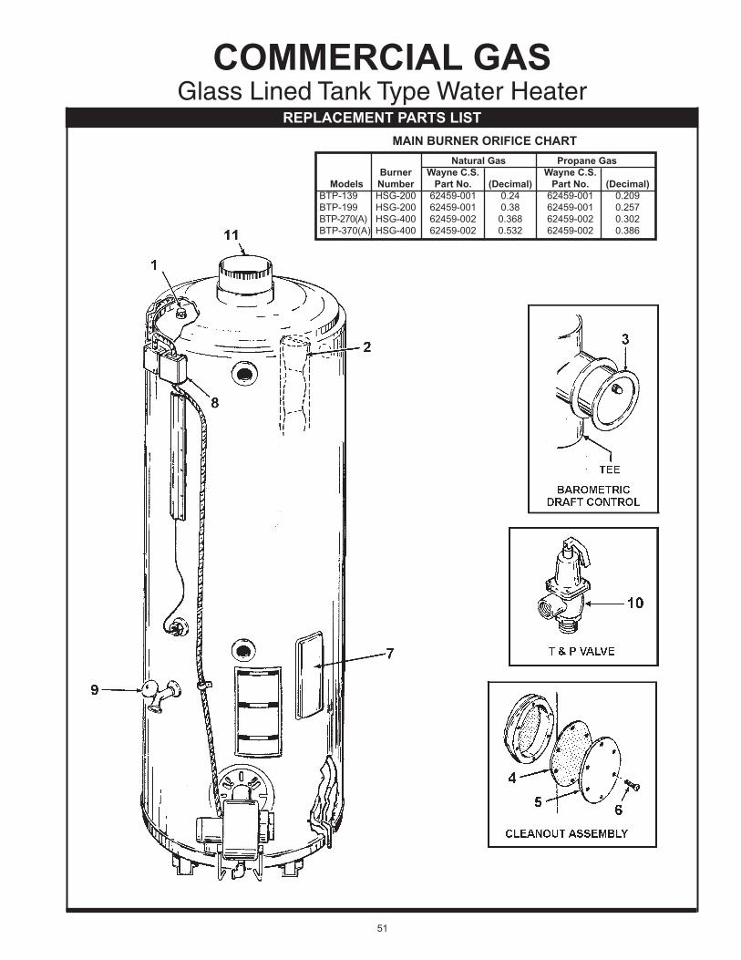
Natural Gas Propane Gas Burner Wayne C.S. Wayne C.S. Models Number Part No. (Decimal) Part No. (Decimal) BTP-139 HSG-200 62459-001 0 24 62459-001 0 209 BTP-199 HSG-200 62459-001 0 38 62459-001 0 257 BTP-270(A) HSG-400 62459-002 0 368 62459-002 0 302 BTP-370(A) HSG-400 62459-002 0 532 62459-002 0 386
MAIN BURNER ORIFICE CHART
COMMERCIAL GAS Glass Lined Tank Type Water Heater
REPLACEMENT PARTS LIST
51

*Items not illustrated ( ) Re e ts quantitiesAll information su h as model and series number, type of gas and spe i ations must tobe supplied to State Water Heaters
Item Description BTP-139 BTP-199 BTP-270, 270A BTP-370, 370A
1 Anode 9003892005(2) 9003892005(2) 9003892005(2) 9003892005(2) 2 Baf e, Flue 9005293205(7) 9005293205(7) 9005293205(7) 9005293205(7) 3 Barometri Draft Control w Tee Assy 9500007199 9500007199 9500007200 9500007200 Cleanout Assembly: 4 Gasket 9004099215 9004099215 9004099215 9004099215 5 Pressure Plate 9005797205 9005797205 9005797205 9005797205 6 S rew, Self Tapping (Req d) 9004100215 9004100215 9004100215 9004100215 7 Cover, Cleanout Opening 181260 181260 181260 181260 8 Thermostat with ECO 9004529005 9004529005 9004529005 9004529005 9 Valve, Drain 9003906015 9003906015 9003906015 9003906015 10 Valve, T & P 9005903205 9005903205 9005903205 9005903205 11 Redu er, Flue 76707-0 76707-0 76707-4 76707-4
52

NOTES
53

NOTES
54

EFFECTIVEFor 3 Years, in the event of a tank leak, we will repair or, at our dis retion, repla e the defe tive water heater
For 1 Year, in the event of part failure, we will repair or, at our dis retion, repla e the defe tive part
We warrant this produ t against defe ts in materials or workmanship as des ribed in this do ument if installed within the United States or Canada and provided the produ t remains at its original pla e of installation
Warranty overage begins the date of installation OR the date of manufa ture if installation annot be veri ed
WHAT'S COVEREDSubje t to these terms, in the event of defe t in materials and/or workmanship resulting in a tank leak during the rst three years, we will Repla e the water heater should the tank leak
Subje t to these terms, in the event of a defe t in materials and/or workmanship appearing during the rst year, we will Repair or, at our dis retion, repla e any part of the water
heater overed under this limited warranty ex luding parts subje t to normal maintenan e (Example non-ele troni anode rod, lter, et )
Service/labor, shipping, delivery, installation, handling or any other costs are not covered at any time under this warranty.Any repla ement part or produ t will be warranted only for the unexpired portion of the original water heater s limited warranty period
If an identi al model is no longer available due to a hange in law, regulation, or standard, we will repla e the produ t with one having omparable apa ity and input In these instan es, the owner will
have the option of paying the differen e between what was paid for the original model and the new model with the additional features, or re eiving a refund of the portion of the pur hase pri e, on a pro-rata basis allo able to the unexpired portion of the warranty
WHAT'S NOT COVERED Problems aused by improper gas supply line sizing, gas type,
venting, onne tions, ombustion air, voltage, wiring, or fusing Failure to follow appli able odes Failure to follow printed instru tions Abuse, misuse, a ident, re, ood, A ts of God Improper installation, sizing, delivery, or maintenan e Claims related to rust, noise, smell, or taste of water Failure to ondu t authorized fa tory start up if required Alterations to the water heater Non-outdoor heaters installed outdoors Damages due to a failure to allow for thermal expansion Heat ex hanger failure due to la k of adequate / proper supply
of water Heaters moved from their original lo ation Servi e trips to explain proper installation, use, or maintenan e
of the produ t/unit or to des ribe omplian e requirements under appli able odes and regulations
Charges related to a essing your heater in luding but not limited to door/wall removal, equipment rental, et
Repla ement parts after expiration of this warranty
LIMITATIONSNOTWITHSTANDING ANYTHING ELSE TO THE CONTRARY, THIS IS YOUR SOLE AND EXCLUSIVE WARRANTY ALL OTHER WARRANTIES INCLUDING A WARRANTY OF MERCHANTABILITY OR FITNESS FOR PARTICULAR PURPOSE ARE EXPRESSLY DISCLAIMED SELLER SHALL NOT BE LIABLE FOR ANY CONSEQUENTIAL, INCIDENTAL, SPECIAL, PUNITIVE OR OTHER INDIRECT DAMAGES TOTAL LIABILITY ARISING AT ANY TIME SHALL NOT EXCEED THE PURCHASE PRICE PAID WHETHER BASED ON CONTRACT, TORT, STRICT LIABILITY OR ANY OTHER LEGAL THEORY
SERVICE INQUIRIES:For service inquiries call the telephone number listed below. Be prepared to provide the following information name, address, and telephone number the model and serial number of the water heater proof of installation and a lear des ription of the problem
For your re ords, fill in the produ t
Serial ___________________Model ___________________ U S Customers Canadian Customers
A. O. Smith Corporation P. O. Box 310 – 768 Erie Street 500 Tennessee Waltz Parkway Stratford (Ontario) N5A 6T3 Ashland City, Tennessee 37015 800-265-8520 800-527-1953 www.hotwater.com
COMMERCIALWATER HEATER
LIMITED WARRANTY
55

500 Tennessee Waltz Parkway, Ashland City, TN 37015Te hni al Support 800-527-1953 Parts 800-433-2545
www.hotwater.com
Copyright 2014 A O Smith, All rights reserved