collaborative data processing on mobile handsets · collaborative data processing on mobile...
TRANSCRIPT

Collaborative Data Processing on Mobile Handsets
Diploma Thesis
Jan Kettner
Matriculation number: 3659580
Freie Universität Berlin
Department of Mathematics and Computer Science
Institute for Computer Science
June 29th 2010
Examiner:
Prof. Dr. Mesut Günes
Tutor:
Georg Wittenburg, M. Sc.


Abstract
Mobile phones have become a basic commodity and smartphone devices claim a continuously increasing market share. Modern smartphone devices are equipped with powerful processing units and high speed mobile internet capabilities. Mobile operators in turn are offering a wide variety of data plans. These developments will lead to an increase of internet access from mobile devices. At the same time the internet is not solely used anymore for displaying data but collaborative editing, evaluation and distribution of data in any form has become widely popular, as can be seen in the so-called “Web 2.0” services. Suppliers are offering versions of these services that are especially designed for mobile devices.
Today Peer-to-Peer networks are responsible for a considerable amount of the total internet traffic. Although Peer-to-Peer networks mainly gained attention in the media for copyright infringement cases Peer-to-Peer networks offer many positive characteristics. Peer-to-Peer networks are decentralized, self-organizing, scalable and offer no single point of failure. This makes Peer-to-Peer networks an ideal candidate for deploying mobile web services.
The MobP2P base system is a foundation for developing Peer-to-Peer based applications for collaborative data processing developed for the Android platform. Applications built on top of the MobP2P base system enable users to create data items and to share these with remote users. Alterations to these data items are automatically synchronized on authorized devices.


Acknowlegdements
I would like to thank Georg Wittenburg who relentlessly supported me with feedback throughout this diploma thesis. I could always rely on him for helping me, pointing out problems and supporting me in finding solutions.
I would also like to thank my family for their support without whom this thesis would not have been possible. Especially I need to thank my brother Henning for proof reading this thesis.


Contents
1 Introduction....................................................................................................................................11
1.1 Evolution of Smartphones........................................................................................................11
1.2 Peer-to-Peer Systems...............................................................................................................14
1.3 Motivation for Mobile Peer-to-Peer ........................................................................................16
1.4 Contributions...........................................................................................................................17
1.5 Overview..................................................................................................................................18
2 Smartphone Platforms..................................................................................................................19
2.1 Overview of Smartphone Platforms........................................................................................19
2.1.1 WebOS.............................................................................................................................19
2.1.2 Maemo.............................................................................................................................20
2.1.3 MobLin.............................................................................................................................21
2.1.4 MeeGo..............................................................................................................................22
2.1.5 LiMo.................................................................................................................................23
2.1.6 Bada ................................................................................................................................23
2.1.7 Openmoko Linux.............................................................................................................24
2.1.8 Windows Phone 7.............................................................................................................25
2.1.9 Blackberry Device Software............................................................................................26
2.1.10 Symbian OS...................................................................................................................26
2.1.11 iPhone OS.......................................................................................................................28
2.2 Android....................................................................................................................................29
2.2.1 Open Handset Alliance.....................................................................................................30
2.2.2 Dalvik VM.......................................................................................................................30
2.2.3 Android SDK....................................................................................................................31
2.2.4 Android Tools...................................................................................................................31
2.2.5 Android Application Components....................................................................................33
2.2.6 Android NDK...................................................................................................................34
2.2.7 Android Market................................................................................................................35
2.2.8 Android Developer Challenge..........................................................................................35
2.2.9 Android Dev Phone..........................................................................................................36
2.3 Comparison of Smartphone Platforms.....................................................................................36

3 Peer-to-Peer Protocols...................................................................................................................37
3.1 Overview of Peer-to-Peer systems...........................................................................................37
3.1.1 Freenet..............................................................................................................................37
3.1.2 Chord ...............................................................................................................................38
3.1.3 CAN.................................................................................................................................39
3.2 Pastry.......................................................................................................................................39
3.2.1 Pastry Node State.............................................................................................................40
3.2.2 Pastry Routing .................................................................................................................40
3.2.3 Example of Pastry's routing algorithm.............................................................................41
3.2.4 Pastry routing performance..............................................................................................42
3.2.5 Pastry API........................................................................................................................43
3.2.6 Self - organization and adaptation....................................................................................43
3.2.7 Locality ...........................................................................................................................44
3.2.8 Experimental Results ......................................................................................................45
3.3 Peer-to-Peer systems based on the Pastry protocol..................................................................46
3.3.1 MADPastry......................................................................................................................46
3.3.2 Scribe...............................................................................................................................47
3.4 Security in Peer-to-Peer Networks...........................................................................................47
3.5 Comparison of Peer-to-Peer Systems......................................................................................48
4 MobP2P - Base System..................................................................................................................50
4.1 Concept ...................................................................................................................................50
4.1.1 Motivation........................................................................................................................50
4.1.2 Design Goals....................................................................................................................52
4.2 MobP2P Base System Architecture.........................................................................................54
4.2.1 MobP2P Base System......................................................................................................54
4.2.2 MobP2P Message Types..................................................................................................56
4.2.3 MobP2P Message Handling.............................................................................................61
4.2.4 Creating and Sharing data items......................................................................................64
4.3 MobP2P Base System implementation....................................................................................65
4.3.1 Pastry configuration values..............................................................................................65
4.3.2 Identifying and addressing...............................................................................................66
4.3.3 Implementation of the three perspectives of data items...................................................68
4.3.4 Pastry implementation......................................................................................................69
4.3.5 Messaging........................................................................................................................72

4.3.6 MobP2P API.....................................................................................................................74
4.3.7 Testing network applications using the Android Emulator..............................................75
5 Example Application.....................................................................................................................77
5.1 Concept....................................................................................................................................77
5.2 Interaction between base system and example application.....................................................77
5.3 Implementation of the example application.............................................................................79
5.3.1 Application package.........................................................................................................79
5.3.2 GUI package....................................................................................................................80
5.4 Possible future applications ....................................................................................................85
6 Conclusion......................................................................................................................................88
6.1 Summary..................................................................................................................................88
6.2 Future work..............................................................................................................................88
Bibliography......................................................................................................................................90
List of Figures...................................................................................................................................96
List of Tables.....................................................................................................................................98


1 Introduction
In his article “The Computer for the 21st Century” [46], Mark Weiser envisions a future were the personal computer would undergo a similar evolution as the machine in the industrial revolution. According to Weiser, computers will transform from huge single purpose machines to multi purpose devices that would blend into the background. Users would not only have one computer but many. In his article Weiser explicitly states, that the change he foresees is not about people being able to carry their personal computer to the beach but computers being everywhere and not being seen. On today's beaches almost all people carry their mobile phones or smartphones. Modern smartphones are a powerful combination of PDA, calendar, digital camera, navigation utility, web browser, e-mail device and gaming console, resting in the background in peoples pockets and bags.
1.1 Evolution of Smartphones
Today, mobile phones are a basic commodity. The market research institute Gartner predicts that by 2013 the number of internet-capable mobile phones will be greater than the number of personal computers [11]. According to Gartner, by 2013 there will be 1,82 billion internet-capable mobile phones and 1,78 billion personal computers.
For many years smartphones, mobile phones with added functions and features, like the Nokia Communicator Series have been available but did not meet a wide market interest. Two events in 2007 changed that situation. The first is the announcement of the Apple iPhone in January 2007. Technologically the iPhone was no revolution. The initial iPhone did not support UMTS, it had only a 2 MP camera and no GPS. By 2007 there were phones on the market like the Nokia N95 which supported data transfer via HSDPA and was equipped with GPS and a 5 MP camera.
The added value of the iPhone was its capacitive touchscreen that could easily be used with a finger and the intuitive usability of the iPhone operating system. The hype that followed the commercial launch, with 270.000 sold units in the first two days can only be explained with the lifestyle image of Apple products and their value as status symbols.
The second event was the announcement of the Android operating system by Google and the Open Handset Alliance in the fall of 2007. One of Google's motivations for developing an operating system was the skyrocketing increase in search queries originating from mobile devices. Between May and June of 2007 alone, search queries from mobile devices registered a 35% increase. However, it was not easy for users to use Google as a search engine from mobile devices. Verizon, for example, routed all search queries to a Verizon owned search engine. With the Android operating system Google gained the possibility to deploy their services like Google Search or Google Mail on mobile devices [25].
The Open Handset Alliance is a group of currently 71 technology and mobile companies “committed to commercially deploy handsets and services using the Android platform” [12]. It combines software developers (Google, Ebay) with semiconductor companies (Intel, Qualcomm), handset manufacturers (HTC, Motorola) and mobile operators (T-Mobile, Sprint).
The operating system Android was published in October 2008 one day before the market launch of
11

the Google G1, the first phone running the Android operating system. One of the major advantages of Android concerning handset manufacturers is that compared to other operating systems like Windows Mobile no licensing fees are due for using Android.
These two events transformed the market for smartphones and many manufacturers of mobile phones began introducing a wider range of smartphones themselves. Most of them were equipped with large capacitive touchscreens.
As of 2010, a Bitkom study projects a 47% increase in sold units for 2010 expecting 8.2 million smartphones to be sold in Germany, while the overall sales increase in mobile phones amounts to a mere 4 percent, for a total of 28 million units [15].
Google Nexus One Nokia Communicator 9000Release Date 2009 1997Manufacturer HTC NokiaProcessor Qualcomm Snapdragon, 1 GHZ Intel 80386, 24 MHZStorage 512 MB internal
+ 4GB SD card8 MB
Operating System Android 2.1 DOS basedData Transfer HSDPA (7,2 Mbit/s) GSM based (9,6kbit/s)Standby Time (h) 290 2
Table 1: Comparison between Nexus One and Nokia Communicator
Gartner draws a similar picture, predicting a 97% increase in sales of mobile phones with a capacitive touchscreen for a total of 362.7 million units worldwide [22]. For comparison, Gartner predicts personal computer sales to the amount of 366.1 million units in 2010. As a side note: About 55% of these personal computers will be mobile computers.
12

A compelling reason for such an increase can be found by examining the increase in the capabilities of mobile phones over the last years. For example, in 1996 Nokia introduced the Communicator 9000 at the CEBIT fair. It had an Intel 80386 chip with 8 MB of internal storage. It used the GSM 900 MHZ band and supported data transfer rates of 9,6 kbit/s. It had the ability to send email as well as displaying a subset of HTML, for which Nokia had to maintain a list of pages that could be viewed with the Communicator. The Communicator had a standby battery life of 24 hours and its operating system was DOS based [13].
In contrast, the Google Nexus One, produced by HTC, has a 1 GHZ Qualcomm processor, 512 MB internal flash memory with a 4GB SD Card. It supports UMTS, GSM/EDGE and data transfer with HSDPA. Its standby time is up to 290 hours and it is running the Android 2.1. operating system [14]. A comparison of both devices can be seen in Table 1.
With larger screen sizes and better processing units a new array of applications for mobile phones were possible ranging from games to social networking. The introduction of the iPhone App Store gave software developers an opportunity to create applications that could be easily and directly marketed to end users. The App Store started in July 2008 and by November 2009 users had access to more than 100.000 so-called apps. At the same time about 2 billion applications had been sold [19]. Developers responded with great interest. According to Apple, the iPhone SDK was downloaded 800.000 times and Apple recognizes around 125.000 active developers working on applications for the iPhone.
Again this behavior was mimicked by others, for example, by the Android Market or the Marketplace introduced for Windows Mobile 6.5. Even Amazon announced an App Store for their ebook-reader Kindle, although it only features a black and white electronic ink screen.
This development was accompanied by an exponential increase in mobile internet traffic causing mobile service providers to offer flat rate data plans for mobile internet use. Although internet use from mobile devices has not been highly popular in the recent years [21], there is a point in the foreseeable future in which a majority of users will have a constant connection to the internet via a mobile phone. For example, Gartner estimates that by 2010, more than 50% of cellular subscribers in the U.S. and Western Europe will access the internet from a mobile device at least once a week [20].
Having devices that are always connected to the internet, opens huge possibilities for designing applications for mobile phones. This includes the development of the internet over the last years often described by the keyword “Web 2.0” [47]. Collaborative editing, evaluation and distribution of data in any form has become widely popular. Some examples are services such as Youtube, Flickr, Facebook or Twitter.
The interest in accessing these services from mobile devices is rising. There are iPhone applications for accessing Facebook and Youtube. The iPhone application for Flickr enables the user to directly upload photos taken with the iPhone. On the other hand, to support a wider range of platforms there are adjusted versions of the Facebook web page especially targeting access from mobile phones. Current versions of these “Web 2.0” services for mobile devices only support a subset of functions of the original services and tend to miss out to take advantage of the unique possibilities that mobile devices provide. Mobile devices are continuously accessible, accompanying users in every day life. Most modern smartphones also contain GPS locating capabilities offering an immense potential for the development of location based services. The desire to harvest that potential can be observed by
13
examining the winners of the Android Developer Challenge [23] where a majority of applications integrated GPS functionality and accessed the internet. The results of the Android Developer Challenge showed on the one hand a cross section of how mobile applications may alter every day use of mobile technology and on the other hand how much potential there is for the development of new applications for mobile devices.
1.2 Peer-to-Peer Systems
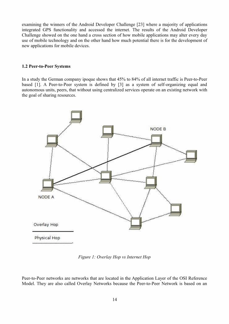
In a study the German company ipoque shows that 45% to 84% of all internet traffic is Peer-to-Peer based [1]. A Peer-to-Peer system is defined by [3] as a system of self-organizing equal and autonomous units, peers, that without using centralized services operate on an existing network with the goal of sharing resources.
Peer-to-Peer networks are networks that are located in the Application Layer of the OSI Reference Model. They are also called Overlay Networks because the Peer-to-Peer Network is based on an
14
Figure 1: Overlay Hop vs Internet Hop

existing network like the internet. Therefore, a connection in a Peer-to-Peer network does not necessarily correspond to an existing internet connection, as can be seen in Figure 1.
Contrary to the classic client server architecture used in protocols like FTP or Telnet, all nodes of a Peer-to-Peer Network share the same functions, so that every node acts as client and server at the same time, as can be seen in Figure 2. The advantage of this strategy is that there is no single point of failure. In a classic client server architecture, the whole network may fail to function if the central server node fails. By contrast, Peer-to-Peer networks may still function even if a larger portion of the nodes fail. In most cases, if one node is no longer reachable other nodes pick up its responsibilities. Different implementations of Peer-to-Peer networks offer different strategies how node departure is handled.
Another advantage of Peer-to-Peer networks is scalability. In the classic client server architecture, a rise in client nodes needs to be handled by deploying a larger amount or more powerful server nodes. In a Peer-to-Peer network this is not necessary because in the ideal case network load is distributed evenly among the network nodes. Therefore, Peer-to-Peer networks scale well. Peer-to-Peer networks also provide greater anonymity for its users. In a classic client server architecture all communication is routed over a central server which makes it easy to log information concerning single users.
Peer-to-Peer networks first gained worldwide attention with the file sharing service Napster. In February 2001 over 80 million users used Napster with approximately 2 billion files shared [10]. Napster was quickly forced to shut down their services in July of 2001 after being sued by record companies like A&M for copyright infringement. Although Napster was no longer available many other file sharing services followed generating massive amounts of network traffic.
Napster claimed mainstream attention but the concept of Peer-to-Peer systems itself was not new. An example would be Usenet news. The Usenet news service was established in 1979 and has been called an ancestor of modern Peer-to-Peer systems [2], since Usenet uses a semi-distributed architecture [24].
15
Figure 2: Peer-to-Peer Architecture vs Client Server Architecture

First generation Peer-to-Peer systems like Gnutella [4] or Kazaa [5] did make no implications on the networks concerning their structure. Therefore, these first generation networks are called unstructured Peer-to-Peer networks. Due to their lack of structure nodes connect to each other at random. For one node sending a message or request to another node the message needs to be broadcasted to all other nodes. Therefore, unstructured Peer-to-Peer networks put enormous strain on network connections and do not scale well. One way of dealing with these issues were hybrid systems like Napster using central servers for look-up services.
Since its early beginning, there has been a considerable amount of research into Peer-to-Peer networks leading to a second generation of Peer-to-Peer networks called structured Peer-to-Peer networks which propose Distributed Hash Tables (DHT) [6,7,8] used to partition the namespace of a network based on consistent hashing. A DHT is a distributed data structure that maps keys onto values and may impose certain naming restrictions on the nodes of a Peer-to-Peer network, introducing key based routing, where each entry in a DHT is responsible for a certain area of a Peer-to-Peer network. Therefore, messages are not broadcasted anymore as with unstructured Peer-to-Peer networks, but they are forwarded according to their destination to that entry in the DHT which is responsible for the destination node. In the Pastry protocol [7] for example, messages are routed to that node that shares a longer ID prefix with the target node than the originating node.
As a result, message delivery or data lookup can be achieved efficiently, depending on the implementation of the DHT in O(log N) time [3], with N as the number of network nodes, so that DHTs can be an efficient building block for a wide array of distributed applications.
Today, Peer-to-Peer technology is not only used in illegal file sharing services but are also utilized for IPTV services, Skype, the most widely used internet phone application, and a variety of instant messaging and online chat services.
1.3 Motivation for Mobile Peer-to-Peer
Modern handsets are capable of running complex applications, such as creating and storing data. The development of mobile data plans offered by mobile operators tends toward a permanent network connection, a so called “always on” state. This enables users to run modern web based applications like social networking or other forms of collaboration on their mobile phones. Since the gap between mobile devices and wired devices has been reduced greatly concerning aspects like connectivity and capabilities, arguments for deploying Peer-to-Peer based applications on wired systems also apply to wireless and mobile devices.
Furthermore, mobile operators can use Peer-to-Peer based applications to reduce costs, by avoiding the need to install a server infrastructure, as well as reducing traffic on an existing server infrastructures. Users are, in part, “used to” Peer-to-Peer technology as described above. So, porting Peer-to-Peer services to mobile devices won't meet the hesitancy that usually comes with introducing new technology.
Mobile devices are not limited to consume data anymore but are capable of creating and storing data [18], sharing that data would be the next logical step. Peer-to-Peer based systems provide an efficient and cost effective means for sharing data.
Although the performance of modern mobile high capability devices like smartphones has improved
16

greatly there is still a gap between mobile devices and personal computers. For this reason there are certain limitations to mobile Peer-to-Peer networks. One limitation is the limited communication throughput. Depending on the mobile device model there is an upper bound to network bandwidth that is almost always considerably smaller than the bandwidth of personal computers. This may put a strain on applications that require high network traffic. Another possible limitation is the dynamic and unpredictable network topology [16]. Applications or protocols, that require a peer to have a fixed geographical location may not be suited for mobile Peer-to-peer networks.
1.4 ContributionsThis work presents a system for collaborative data processing. It provides an easy to use and efficient means to share data on distributed devices implemented for the Android operating system. Users can create data on their Android devices which will be automatically updated on other authorized Android devices. The system is based on an underlying Pastry Peer-to-Peer network [7] and makes use of the advantages of Peer-to-Peer systems mentioned above like scalability, fault tolerance and efficient routing.
We present the MobP2P base system prototype, that implements the system described. The base system has been designed to be completely reusable. Multiple applications can be easily built on top of the base system accessing it through the MobP2P API and creating or connecting to a Pastry
17
Figure 3: System Overview
based Peer-to-peer network. With a few steps a user can create or subscribe to “shared objects”. Shared objects are stored on external nodes reducing traffic on the node that owns the shared object by distributing to and retrieving them from the external node.
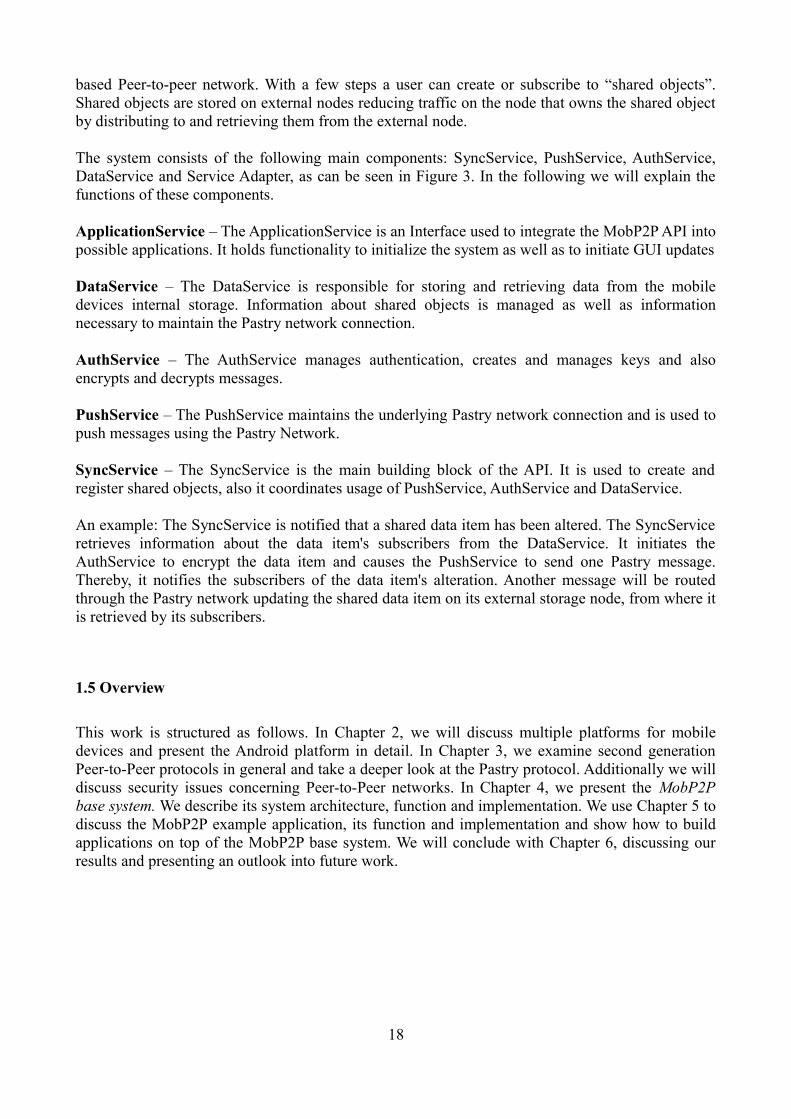
The system consists of the following main components: SyncService, PushService, AuthService, DataService and Service Adapter, as can be seen in Figure 3. In the following we will explain the functions of these components.
ApplicationService – The ApplicationService is an Interface used to integrate the MobP2P API into possible applications. It holds functionality to initialize the system as well as to initiate GUI updates
DataService – The DataService is responsible for storing and retrieving data from the mobile devices internal storage. Information about shared objects is managed as well as information necessary to maintain the Pastry network connection.
AuthService – The AuthService manages authentication, creates and manages keys and also encrypts and decrypts messages.
PushService – The PushService maintains the underlying Pastry network connection and is used to push messages using the Pastry Network.
SyncService – The SyncService is the main building block of the API. It is used to create and register shared objects, also it coordinates usage of PushService, AuthService and DataService.
An example: The SyncService is notified that a shared data item has been altered. The SyncService retrieves information about the data item's subscribers from the DataService. It initiates the AuthService to encrypt the data item and causes the PushService to send one Pastry message. Thereby, it notifies the subscribers of the data item's alteration. Another message will be routed through the Pastry network updating the shared data item on its external storage node, from where it is retrieved by its subscribers.
1.5 Overview
This work is structured as follows. In Chapter 2, we will discuss multiple platforms for mobile devices and present the Android platform in detail. In Chapter 3, we examine second generation Peer-to-Peer protocols in general and take a deeper look at the Pastry protocol. Additionally we will discuss security issues concerning Peer-to-Peer networks. In Chapter 4, we present the MobP2P base system. We describe its system architecture, function and implementation. We use Chapter 5 to discuss the MobP2P example application, its function and implementation and show how to build applications on top of the MobP2P base system. We will conclude with Chapter 6, discussing our results and presenting an outlook into future work.
18

2 Smartphone Platforms
In the following chapter, we will present an overview of existing smartphone platforms and take an in-depth look at the Android platform. To have some kind of means of comparison we will focus on the following aspects. Who develops the platform? When was it released? What kind of kernel does it use? What kinds of devices are available for the platform? Is there an SDK available for the platform? How can third party developers distribute their applications? What distinguishes the user interface?
2.1 Overview of Smartphone Platforms
2.1.1 WebOS
WebOS [33] was released in January 2009 by Palm and is the successor of PalmOS. WebOS is based on the Linux kernel and supports multitasking. Users may browse through several active applications in a live preview, in which even video playback is supported. WebOS also supports finger gestures like multi-touch. WebOS is not downward compatible with PalmOS but the platform can emulate PalmOS applications.
There is an SDK available called Mojo Application Framework that enables users to code applications in HTML 5, CSS and JavaScript. The IDE Ares that contains a WebOS emulator gives
19
Figure 4: Web OS User Interface [62]
developers the opportunity to develop applications directly in their browser. Currently Firefox and Safari are supported. With a plug-in developers may even create applications in C or C++. Developers may distribute their applications in the Palm App Catalog.
The first device for the WebOS platform was released in June 2009 with the Palm Pre. In fall of 2009 the Palm Pixi followed.
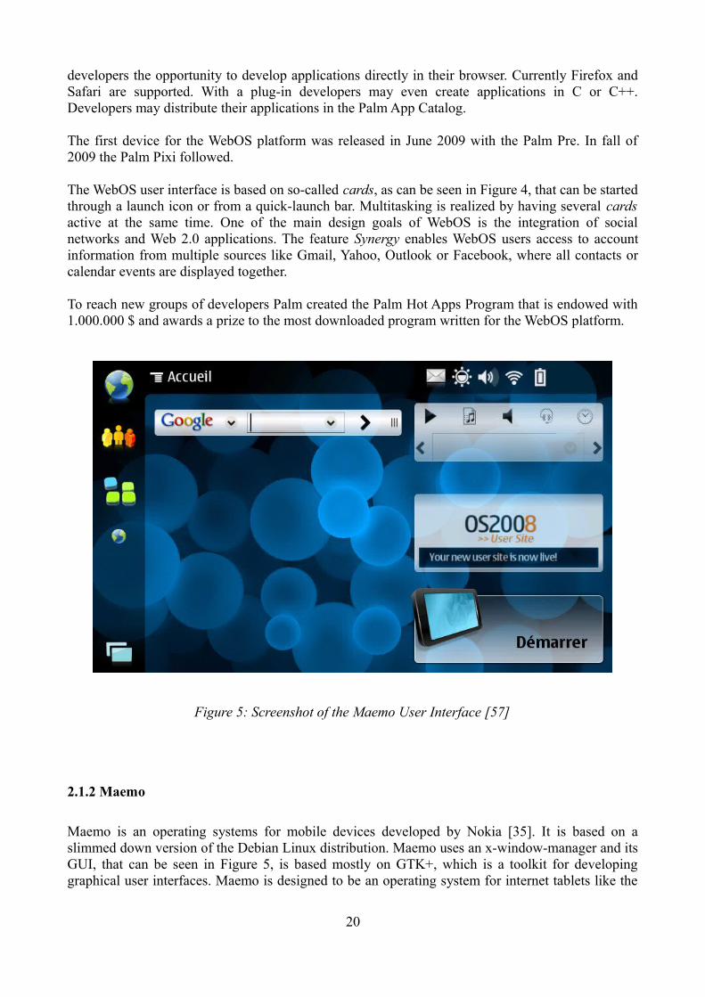
The WebOS user interface is based on so-called cards, as can be seen in Figure 4, that can be started through a launch icon or from a quick-launch bar. Multitasking is realized by having several cards active at the same time. One of the main design goals of WebOS is the integration of social networks and Web 2.0 applications. The feature Synergy enables WebOS users access to account information from multiple sources like Gmail, Yahoo, Outlook or Facebook, where all contacts or calendar events are displayed together.
To reach new groups of developers Palm created the Palm Hot Apps Program that is endowed with 1.000.000 $ and awards a prize to the most downloaded program written for the WebOS platform.
2.1.2 Maemo
Maemo is an operating systems for mobile devices developed by Nokia [35]. It is based on a slimmed down version of the Debian Linux distribution. Maemo uses an x-window-manager and its GUI, that can be seen in Figure 5, is based mostly on GTK+, which is a toolkit for developing graphical user interfaces. Maemo is designed to be an operating system for internet tablets like the
20
Figure 5: Screenshot of the Maemo User Interface [57]

Nokia N900 or smartphones. Maemo is backed by a community with over 22.000 registered developers.
Applications may be distributed over the Maemo Garage, if they are free of charge, or else the Maemo Application Store. Applications with high quality are also presented on the Nokia owned Maemo website. Additional applications may be installed with the pre-installed Application Manager and also with apt or dpkg.
With the Maemo SDK there is an IDE for the development of applications for Maemo available for Linux operating systems.
2.1.3 MobLin
MobLin (mobile Linux) is an operating system developed by Intel designed for mobile internet devices like smartphones and netbooks [36]. The GUI, that can be seen in Figure 6, is based on GTK+ and the Clutter software libraries for creating dynamic user interfaces .
MobLin has been used as an operating system for the Foxconn SZ901 netbook or the LG LGW990 smartphone. MobLin was originally designed to run on the Intel Atom chip, but MobLin also provides support for other chip-sets that support the SSSE3 instruction set.
A MobLin SDK is available for the Ubuntu and Fedora Core Linux distributions. For running and testing applications developed with the MobLin SDK, a device running MobLin is recommended since there is no MobLin emulator. There is also a plug-in for the Eclipse IDE available.
21
Figure 6: Intel MobLin User Interface [59]

The MobLin Image Creator gives users the opportunity to decide which software and packages to include in their MobLin installation, giving users the opportunity to configure MobLin according to their needs, as opposed to other platforms that only offer pre-installed software builds on their devices.
2.1.4 MeeGo
MeeGo [34] is a joint project by the companies Intel and Nokia and is the successor to their smartphone platforms MobLin and Maemo. The first release of MeeGo can be expected in the second half of 2010.
MeeGo is an open source operating system for mobile devices that is based on the Linux kernel and will support ARM and x86 processors.
The MeeGo user interface, that can be seen in Figure 7, will be mainly based on the cross-platform application and UI framework Qt. For third party developers the IDE QtCreator is available and developers may code applications in C++. QtCreator supports features like code completion, an integrated help and drag and drop UI design. The enclosed Qt libraries are licensed under the LGPL license, so that third party applications may be proprietary or open source. QtCreator is available for
22
Figure 7: Screenshots of the handheld version of the MeeGo UI [58]

Windows, Linux and Mac operating systems.
MeeGo is not only a platform for smartphone devices but is also targeted at being deployed on internet tablets, netbooks, in-vehicle devices, and TVs connected to the internet. Open source applications may be distributed through the MeeGo Garage whereas commercial applications will be made available to users through the MeeGo Application Store.
2.1.5 LiMo
LiMo is a mobile Linux platform developed by the LiMo Foundation [49], a consortium consisting of companies like Vodafone, Motorola, Samsung, LG or ARM. According to the website of the LiMo Foundation, there are currently over 50 million devices in use on which LiMo is deployed. Examples for such devices are the Vodafone 360 M1, that can be seen in Figure 8, and the Vodafone 360 H1 that are available to customers in the UK.
According to the LiMo Foundation website, an SDK will be made available to third party developers at a later time. Information on how third party developers may distribute their applications or the user interface of the LiMo operating system is not available.
2.1.6 Bada
Bada [37] is a mobile operating system developed by Samsung and has been presented in 2010. Samsung plans to provide cost efficient smartphones equipped with Bada. The first phone using
23
Figure 8: Image of the Vodafone 360 M1 and the LiMo User Interface [56]

Bada as an operating system is the Samsung Wave 8500 that has been released in June 2010. The Bada operating system is either based on the Linux kernel or a real time operating system (RTOS) for cheaper devices because of smaller memory requirements.
The Samsung Wave 8500 will feature the Touchwhiz UI, that can be seen in Figure 9. An SDK including an IDE is available for Windows operating systems. Applications for Bada will be developed in C++ or Java ME. There is also a Bada plug-in available for the Eclipse IDE.
A Bada developer challenge, endowed with 2.700.000$ is being planned. Additionally there will be local developer challenges in countries like China, Vietnam, Russia or the Philippines.
2.1.7 Openmoko Linux
The Openmoko Linux project [38] was presented in 2006. The Openmoko Linux platform was completely built with free and open software, which was a novelty at that point. Two handsets were developed for Openmoko Linux, the Openmoko Neo 1973 and the Neo Freerunner, that can be seen in Figure 10. Both devices specifically targeted developers. Openmoko provided base functionality but expected the community to improve the platform. The Freerunner also had a debug port that even provided access to low level system components. An SDK is available for the Windows, Linux
24
Figure 9: A Screenshot of the Bada UI as seen on the Samsung Wave [52]
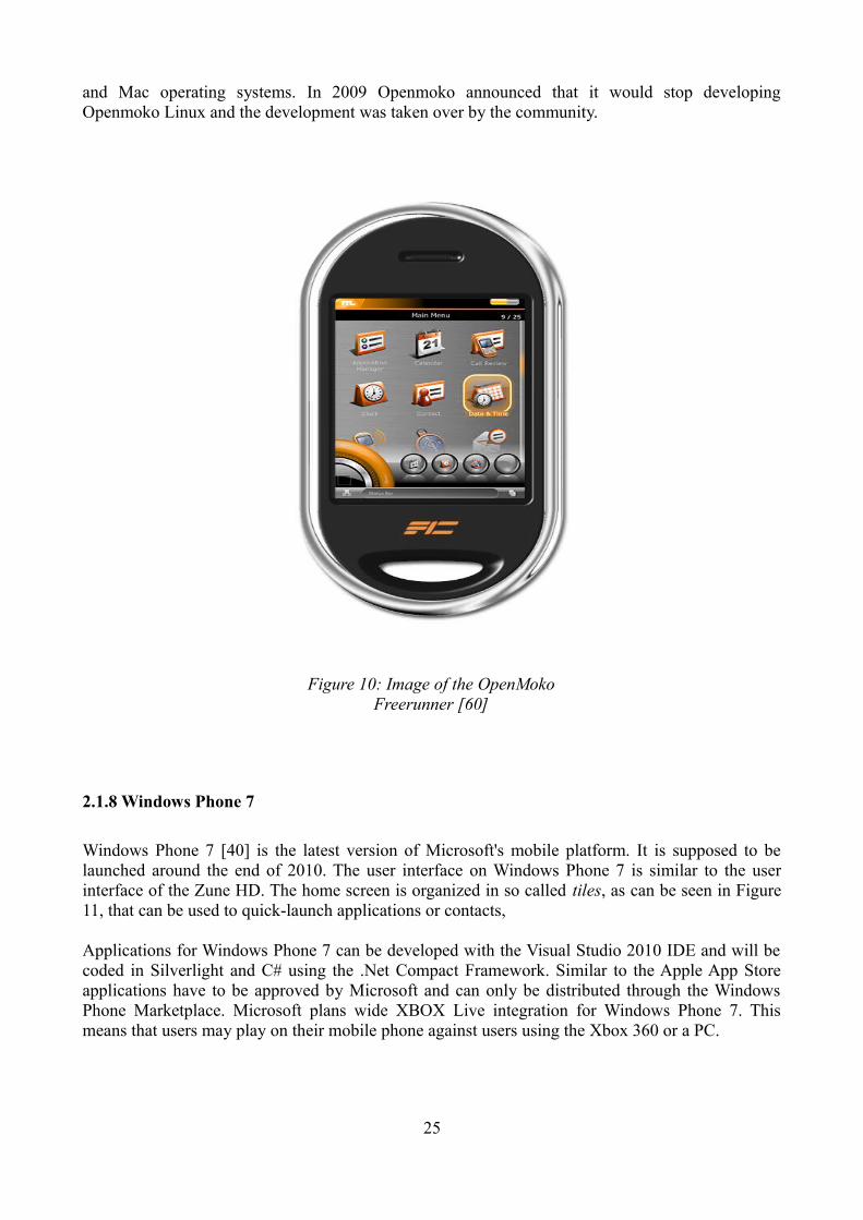
and Mac operating systems. In 2009 Openmoko announced that it would stop developing Openmoko Linux and the development was taken over by the community.
2.1.8 Windows Phone 7
Windows Phone 7 [40] is the latest version of Microsoft's mobile platform. It is supposed to be launched around the end of 2010. The user interface on Windows Phone 7 is similar to the user interface of the Zune HD. The home screen is organized in so called tiles, as can be seen in Figure 11, that can be used to quick-launch applications or contacts,
Applications for Windows Phone 7 can be developed with the Visual Studio 2010 IDE and will be coded in Silverlight and C# using the .Net Compact Framework. Similar to the Apple App Store applications have to be approved by Microsoft and can only be distributed through the Windows Phone Marketplace. Microsoft plans wide XBOX Live integration for Windows Phone 7. This means that users may play on their mobile phone against users using the Xbox 360 or a PC.
25
Figure 10: Image of the OpenMoko Freerunner [60]

2.1.9 Blackberry Device Software
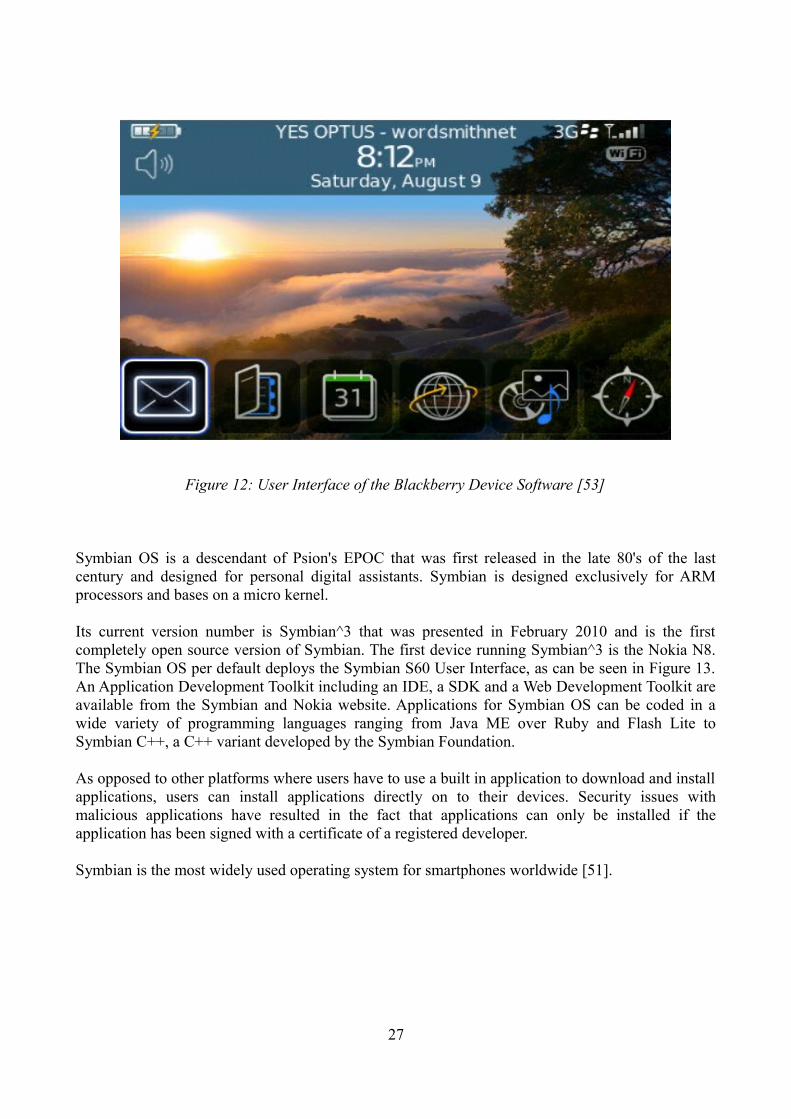
Blackberry Device Software [49] is the operating system developed by Research in Motion (RIM) for their Blackberry devices, as can be seen in Figure 12. The Blackberry Device Software was first released in 1999. It's current version number is 4.5 and current devices featuring this operating system are the Blackberry Curve and the Blackberry Pearl.
Developers have two possibilities for developing applications for Blackberry devices. Either they develop web applications or Java applications. For both strategies there are plug-ins available for the Eclipse IDE. Applications may then be distributed via the Blackberry App World.
The Blackberry Device Software is currently the most widely used smartphone platform on the American market [50].
2.1.10 Symbian OS
Symbian OS is an open source operating system and platform developed by the Symbian Foundation, that was acquired by Nokia in 2008. Originally the foundation was founded by a consortium consisting of companies like, Nokia, Sony Ericsson, Motorola, AT&T, Vodafone and others.
26
Figure 11: The User Interface of Windows Phone 7 [63]
Symbian OS is a descendant of Psion's EPOC that was first released in the late 80's of the last century and designed for personal digital assistants. Symbian is designed exclusively for ARM processors and bases on a micro kernel.
Its current version number is Symbian^3 that was presented in February 2010 and is the first completely open source version of Symbian. The first device running Symbian^3 is the Nokia N8. The Symbian OS per default deploys the Symbian S60 User Interface, as can be seen in Figure 13. An Application Development Toolkit including an IDE, a SDK and a Web Development Toolkit are available from the Symbian and Nokia website. Applications for Symbian OS can be coded in a wide variety of programming languages ranging from Java ME over Ruby and Flash Lite to Symbian C++, a C++ variant developed by the Symbian Foundation.
As opposed to other platforms where users have to use a built in application to download and install applications, users can install applications directly on to their devices. Security issues with malicious applications have resulted in the fact that applications can only be installed if the application has been signed with a certificate of a registered developer.
Symbian is the most widely used operating system for smartphones worldwide [51].
27
Figure 12: User Interface of the Blackberry Device Software [53]

2.1.11 iPhone OS
iPhone OS is the operating system for Apple's iPhone line of smartphones. The first iPhone was released in June 2007. The current model is the iPhone 3GS. The iPhone OS is derived from the MAC OS X operating system and is therefore a Unix like operating system.
The user interface of the iPhone OS, as can be seen in Figure 14, was the first user interface for smartphones that was especially designed for capacitive touchscreens and can therefore by used by the touch of a finger. Key features were direct manipulation and multi-touch gestures.
Apple provides an SDK and an iPhone Simulator for developers. Applications are written in Objective-C, a C variant. Developers may distribute their applications via the iPhone App Store. Apple has received severe criticism about its policy of withdrawing applications from the App Store if they don't meet Apple's criteria for applications.
iPhone OS is currently the second most deployed operating system for smartphones on the American market [50].
28
Figure 13: The Symbian S60 User Interface of the Symbian^3 OS [61]

2.2 Android
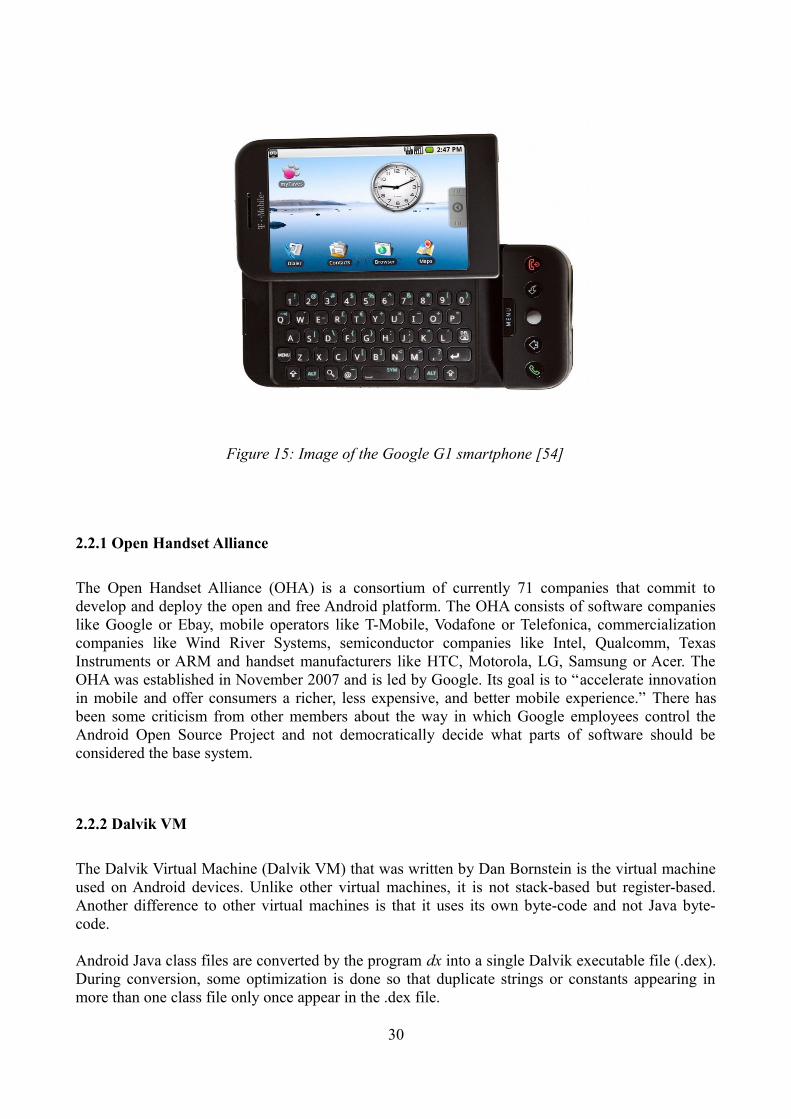
Android [48] is a software stack and mobile platform, based on the Linux kernel, developed and released by the Open Handset Alliance. Android was initially developed by Android Inc. that was later purchased by Google. Android was announced in November 2007 and published in October 2008, when also the first device running the Android operating system the G1, that can be seen in Figure 15, was released. The current version number deployed on devices is as of May 2010 Android 2.1. Android was published under the Apache v2 open source license. This enables members to be able to develop proprietary software for Android without having to submit it back to the open source community. Another main design idea of Android is that all applications, core phone applications or third party applications are treated equally, having equal access to devices capabilities. Also, all parts of Android are interchangeable. Members of the Open Handset Alliance or users may exchange any part of the Android software stack and replace it as they see fit. The Android operating system is the fourth most used operating system for smartphones on the American market [50]. In May 2010 Google stated that daily 100.000 devices running Android are shipped.
29
Figure 14: User Interface of iPhone OS [55]
2.2.1 Open Handset Alliance
The Open Handset Alliance (OHA) is a consortium of currently 71 companies that commit to develop and deploy the open and free Android platform. The OHA consists of software companies like Google or Ebay, mobile operators like T-Mobile, Vodafone or Telefonica, commercialization companies like Wind River Systems, semiconductor companies like Intel, Qualcomm, Texas Instruments or ARM and handset manufacturers like HTC, Motorola, LG, Samsung or Acer. The OHA was established in November 2007 and is led by Google. Its goal is to “accelerate innovation in mobile and offer consumers a richer, less expensive, and better mobile experience.” There has been some criticism from other members about the way in which Google employees control the Android Open Source Project and not democratically decide what parts of software should be considered the base system.
2.2.2 Dalvik VM
The Dalvik Virtual Machine (Dalvik VM) that was written by Dan Bornstein is the virtual machine used on Android devices. Unlike other virtual machines, it is not stack-based but register-based. Another difference to other virtual machines is that it uses its own byte-code and not Java byte-code.
Android Java class files are converted by the program dx into a single Dalvik executable file (.dex). During conversion, some optimization is done so that duplicate strings or constants appearing in more than one class file only once appear in the .dex file.
30
Figure 15: Image of the Google G1 smartphone [54]
The Dalvik VM is slimmed down and optimized for low memory requirements so that multiple instances of the Dalvik VM can run efficiently and simultaneously on an Android device. Androids design goal of all applications being equal to another is realized by every application running in its own Dalvik VM.
2.2.3 Android SDK
The current version number of the Android SDK [44] is 2.2 and was released in May 2010. The Android SDK contains the Android APIs and Android Tools, as can be seen in Figure 16. Some of the Android Tools are explained below in greater detail. Also Android application key components are discussed below.
Applications developed using the Android SDK are coded in Java. The Android APIs included in the Android SDK contain a subset of the JSE APIs. So, for example, AWT and Swing libraries are missing from the Android APIs. Although parts of the JSE APIs are included, Android applications may behave differently than JSE applications.
The Android SDK is available for the Windows, Linux and Mac operating systems.
2.2.4 Android Tools
ADT – The Android Developer Tools (ADT) is a plug-in for the Eclipse IDE containing the Android SDK and other Android tools enabling developers to create applications for the Android platform.
AVD Manager – The Android Virtual Device Manager (AVD Manager) is part of the ADT and enables users to create multiple virtual Android devices, that enable Android developers to install and test their application on emulated Android devices. The AVD Manager gives the developer the opportunity to decide on which Android SDK version they want to test their applications. The AVD Manager is also used to update the ADT.
DDMS – The Dalvik Debug Monitor Server (DDMS) enables developers to debug their Android applications either on an emulated Android device or on an actual Android device that is connected to the development machine through a USB connection. The DDMS can be started from the Eclipse IDE as part of the ADT or as a standalone program from the command line.
The DDMS also grants the developer control over the emulated Android device, giving the developer the possibility to simulate incoming phone calls or text messages as well as manually entering GPS coordinates if their applications should depend on such input.
Another part of the DDMS is the LogCat window. In the LogCat window the DDMS displays all debug and system information that can be filtered by keywords like verbose or error.
ADB – The Android Debug Bridge (ADB) is a client server program that lets the developer manage the state of the emulated Android device. It consists of three parts, a client and a server program that run on the development machine. With the client a developer may issue commands to the server
31

program. The third part of the ADB is a daemon program that runs as a background process on the emulated Android device and applies the users commands. With the ADB developers may forward ports, which is needed for testing networking applications, or copy files to and from the emulated Android device, as well as install applications on the emulated Android device.
32
Figure 16: Collaboration of Android Tools

jarsigner, keytool – All applications destined to run on an Android device, except for dedicated Android Dev Phones, must be signed by a developers certificate. Unlike the Java Verified Program for J2ME, certificates can be created by developers themselves with the keytool program and do not need to be issued by a central authentication authority. For creating a certificate, developers may decide on aspects of encryption algorithms or validity of the certificate. After creating an appropriate certificate, developers package their application into an .apk file and then sign their application with their certificate using the jarsigner program, after which they may for example distribute their applications through the Android Market.
2.2.5 Android Application Components
In the following, we will give a brief summary over some of the key components of Android applications. One of Android's main goals is making parts of an application interchangeable, so that this part may be used by other applications. Therefore, there is no single entry point to an application like a main() method. For example, the user interface component Activity, which we will later discuss, has a life-cycle with several entry points like the OnCreate(), OnStart() methods, that are accessed when an application has first started and cause the specified Activity to be displayed, or the OnResume() method, that is called when another Activity has been displayed on the device, and causes the first Activity to be displayed again.
All components of an Android application, class files, resource and other files are bundled by the aapt tool into an Android Package, an .apk file, where each Android Package represents one application.
The Manifest File
The manifest file is a mandatory part of any Android application and is bundled during the build into the applications .apk file. All of an applications components, like Activities or Intent-Filters are declared in an XML file called AndroidManifest.xml. Additionally an application's permissions and restrictions, like the right to network access, are defined in the manifest file.
Activities
The Activity class is a user interface component for an Android application. An Application may have multiple Activities. For example, a card game application may have one Activity for the game user interface and another Activity where the high-scores are listed.
Each Activity is independent from other Activities and is drawn in its own window. Activities consist of components that are derived from the View class, that specify the visual content drawn by an Activity. Our high-score example may consist of a ListView element, that is drawing a list, with each entry of the list being a TextView element, that displays a name and that persons score. For each Activity there is a corresponding XML layout file, where the visual elements of an Activity are declared.
33
Intents
An Intent is a component of an Android application that may activate other components. In our card game example, when the game has finished, an Intent may be fired that activates the high-score Activity and causes it to be displayed. An Intent may be used to transport bundles of data from one component to another. In our example, after the high-score Activity has been activated, the high-score Activity may receive a data bundle containing the players name and score. It may then decide whether to display that data.
There are two kinds of Intents. There are Intents that are directly targeting a specific component and there are those Intents that do not name a specific target. To “collect” these untargeted Intents an application may declare an Intent-Filter in the manifest file, that defines which kind of Intents it wishes to receive, causing a component to activate if a certain kind of untargeted Intent has been fired.
Services
Services are an Android application component that run for an indefinite time in the background. For example, a Service may wait for a network event. In case that event occurs the Service may fire an Intent and thereby activate and display a certain Activity.
Broadcast Receivers
A Broadcast Receiver is a part of an Android application that receives and reacts to broadcast announcements. A huge majority of broadcast announcements originate in the system code. For example, an application may define a Broadcast Receiver that responds to announcements concerning the user language settings. The Broadcast Receiver may then fire an Intent causing the application that defined the Broadcast Receiver to change its language settings as well. An application may define a variety of Broadcast Receivers. The Broadcast Receiver also may notify the user directly using the NotificationManager. This may cause the handset to vibrate or display a status icon.
Content Providers
Content Providers make certain parts of data of an application available to other applications. For example, there is a Content Provider defined for Androids own address management program, so that other applications may access or alter a users contacts from the users address book.
2.2.6 Android NDK
With Android Version 1.5 the Android Native Development Kit (NDK) [43] was released. The Android NDK is an addition to the Android SDK and is designed to enable developers to code parts of there applications where performance is critical in native code languages like C or C++. The current release of the NDK supports the ARMv5TE and ARMv7-A instruction sets. The support of
34

the x86 instruction set is planned for future releases of the Android NDK. The Android NDK provides developers with a set of system headers for stable native APIs like libc, JNI interface headers or support for 3D graphics with OpenGL ES headers. The corresponding native libraries are embedded by the Android NDK into the application's package files which makes them usable by Android applications.
2.2.7 Android Market
Android Market is a software application for the Android platform that enables Android users to download and install applications on their Android devices. Developers may distribute their applications through the Android Market. As of May 2010 over 60.000 applications were available in the Android Market with approximately 10.000 new applications each month over the previous months. Developers have the opportunity to choose whether to charge for applications or distribute them for free. Currently about two thirds of all applications in the Android Market are free. Developers receive 70% of the revenue of each sold application with the rest being split between the mobile carriers and the payment processors.
There is some controversy around the Android Market because not all developers from all countries may sell applications on the Android Market. Developers from countries like Switzerland, Canada or Australia are exempt from using the Android Market to sell their applications. Unlike the iPhone App Store, Android users are not bound to the Android Market for installing new applications. Android users may install applications from any source as long as the application has been properly signed by the developer.
Similar to Apple's policy, Google reserves the right to ban applications from the Android Market, if the application violates the Android Market Developer Distribution Agreement. In the past, applications, that for example, could be used to download videos from Google's service YouTube, were banned, as well as several applications that enabled tethering, although they were restored to the Android Market later on.
2.2.8 Android Developer Challenge
Android Developer Challenge (ADC) is the name of two programming competitions Google launched in 2008 and 2009 for the most innovative Android applications. Both challenges were endowed with 10.000.000 $ prize money.
The ADC 1 was launched in 2008. Google registered a total of 1778 applications from over 70 countries. A jury formed by members representing the Open Handset Alliance and open source community members picked 50 finalists that each received 25.000 $ prize money. Out of these 50 finalists ten participant teams received an additional 275.000 $ and another ten teams received an additional 100.000 $.
In May 2009, Google launched a second ADC. Developers were to submit applications in ten categories ranging from games over social networking to media centric applications. Winners for each category were chosen in two rounds. In the first round, thousands of Android users were given the opportunity to rank applications from each category. In the second round, the top 10
35

applications from each category were judged again by users as well as a panel of official judges. The overall winners were the applications Sweet Dreams, What the Doodle!? and WaveSecure. The WaveSecure application, amongst other things, gives the user the ability to remotely lock and wipe his Android device in case it was lost or stolen.
2.2.9 Android Dev Phone
In December 2008, Google announced the release of the Android Dev Phone. A handset, that was targeted directly at advanced developers. The Android Dev Phone contained a fully compatible Android system image. Also, it was SIM unlocked and hardware unlocked giving developers the opportunity to test their applications directly on a handset. Even the bootloader was unlocked, enabling developers to flash the device with custom Android builds. Also, applications did not need to be signed with a developers certificate to run on the Dev Phone. For security reasons, the Dev Phone could not connect to the Android Market.
Two versions of the Dev Phone were released. The Android Dev Phone 1 was a HTC Dream device with an Android platform version 1.0. The Android Dev Phone 2 was a HTC Magic device with an Android platform version 1.6. The manufacturer of the device HTC provides developers with the ability to flash the Dev Phone with a factory system image to test applications on multiple Android platform versions or to restore a corrupted device.
2.3 Comparison of Smartphone Platforms
As we have seen, there is a wide variety of smartphone platforms available today. Many share key characteristics like being based on the Linux kernel. The user interfaces of the presented platforms are designed to be accessed with a finger as opposed to a stylus that was common for mobile devices at the beginning of the millennium. Almost all platforms offer some kind of SDK for developers to create applications for that platform. Equally, almost all platforms give third party developers the possibility to distribute their applications over the web through an application installed on the handsets. Some companies have held or will hold competitions for innovative new applications, to draw more developers to their platform. Interestingly, the involvement of many companies in a consortium creating a smartphone platform overlap. For example, Samsung is a founding member of the LiMo Foundation, but also developing its own smartphone platform with Bada. Another example is Motorola. Motorola is a member of the LiMo Foundation, a member of the Symbian Foundation and a member of the Open Handset Alliance.
In this chapter, we gave a broad overview over existing smartphone platforms. We discussed the Android platform in greater detail and explained the interaction of application components and Android tools. Finally, we compared the smartphone platforms according to a set of characteristics.
36

3 Peer-to-Peer Protocols
Peer-to-Peer systems provide functionality to share and distribute data in a decentralized, scalable, fault-resilient and efficient manner. Although Peer-to-Peer systems are discussed in the media mainly in connection with copyright infringement cases, Peer-to-Peer systems have attracted a lot attention from researchers leading to a wide variety of Peer-to-Peer protocols and systems. At the beginning of this millennium unstructured or first generation Peer-to-Peer systems like Gnutella [4] or hybrid systems like Napster [10] have been proposed and widely used. But even before that, shared objects in distributed environments [32] were discussed. The main building block of most Peer-to-Peer systems is a distributed hash table (DHT), a distributed data-structure that maps keys onto values. For certain DHT implementations, keys may refer to a networks nodeId or a data item that is stored in the network.
In this chapter, we will begin with presenting Freenet [26], a first generation Peer-to-Peer protocol and continue with Chord [8] and CAN [6], two second generation Peer-to-Peer protocols. Next, we will discuss and explain the Pastry protocol [7] in detail, give some examples how Pastry's routing works and then examine MADPastry [27], a Pastry implementation for MANETs, and take a look at Scribe [28], a system that has been build on top of the Pastry API. We will conclude this chapter, by discussing security concerns of Peer-to-Peer systems
3.1 Overview of Peer-to-Peer systems
3.1.1 Freenet
The Freenet Information retrieval and storage system is described in [26]. A main concern of the Freenet system is privacy. As the authors state as one of their main goals: „Anonymity for producers and consumers of information“ [26]. The Freenet system can be characterized as a first generation Peer-to-Peer system, because it imposes no structure on the network nodes. Nodes can simply join by connecting to a known node and copying its state information.
Each Freenet node maintains a local data-store, that can service read and write queries from other Freenet nodes. Each node also maintains a dynamic routing table, containing the addresses of other Freenet nodes and the keys they supposedly hold. Freenet tries to overcome the typical problem of first generation Peer-to-Peer networks of not scaling well by imposing certain restrictions on read and write queries.
A query is passed in a chain from one node to the next with each node making a local routing decision in the style of IP routing. Each query has a random identifier to prevent loops, causing nodes that have already seen a certain query identifier to reject that query. Each query also has a hops-to-live count, similar to an IP time-to-live field, to prevent infinite chaining. When the hops-to-live count runs out or the query has reached its destination a failure or a success message is passed back up the chain to the sending node.
Freenet retrieves data by performing a steepest-ascent hill-climbing search with backtracking. When a user wants to retrieve certain information, a hash key according to certain naming specifications is passed from node to node. When the desired information has been found, the data is passed back up
37

the chain to the sending node. After the searching node has retrieved the information, it makes an association between the node that stored the information and the information's key.
These associations are also used for storing information. To store information in the network, a user first creates the appropriate hash key according to the naming conventions and then passes it to the node, that stores the lexicographic closest key. Opposite to retrieving data, for storing data the hops-to-live count marks on how many nodes the data should be stored, because the information is replicated on each node it passes.
To prevent tempering from malicious users, when a storage query reaches a node that already stores the queried hash key, the storage query is treated like a retrieval query and the original information is passed back up the chain. Freenet reaches anonymity, by giving each node in the chain the possibility to claim to be the data's owner or the node that requested that information. This way, the producers and consumers of information maintain their anonymity.
Experimental results with 500 to 900 Nodes and 50 simultaneous queries simulated show that over time the number of average routing hops tends to be approximately 10 hops per query.
3.1.2 Chord
Chord [8] is a distributed look-up protocol that maps distinct keys to nodes. The key can also be used by an application to associate a data item that is stored on a node. Chord's mapping is using a variant of a consistent hash algorithm. Consistent hashing means that only K/n keys need to be remapped on average, where K is the number of keys, and n is the number of slots. In the Chord protocol, keys only need to be remapped when nodes leave or join the network. The main goal of Chord is the efficient location of a node that stores certain data. Chord manages to achieve logarithmic performance only needing O(log N) messages for look-ups, where N is the number of total nodes in the network. Chord only needs to store information about O(log N) other nodes. Events like joining and departing also only cause O(log² N) Messages.
In the Chord protocol all nodes have the same functionality. Chord scales well and information is widely available, which means that Chord updates state information automatically to react to nodes joining or departing. Chord also does not impose naming restrictions on keys, because Chord's namespace is flat.
In the Chord protocol, each node and key is assigned an m-bit identifier computed as an SHA-1 hash of the nodes IP address or the hash of the key. The identifiers are represented in a circle of numbers from 0 to 2m−1 , so nodes are arranged in a ring layout. The successor(k) is defined as the first node clockwise from k.
To achieve better results than linear performance, each node maintains a so called finger table. The i-th entry of the finger table of node n or the i-th finger of n is the successor n2i−1mod 2mwhere 1≤i≤m . Therefore, the first finger of a node is always the successor of that node. A node may now use the finger table for performing look-ups by forwarding the look-up request to that fingers successor that is closest to the targeted identifier. By using the finger table, the “distance” from a targeted identifier halves with each hop.
For maintaining correct values in the finger tables of a network's nodes, when nodes join and depart
38

each node additionally keeps information about its predecessor, because with nodes joining it is important for the circle structure to stay correct. When a node joins the network, it can copy its immediate neighbor's information. This way it simplifies the initialization of correct table states. Since Chord deploys constant hashing, updating the fingers of existing nodes is performed selectively only where updates are necessary. Repairing finger tables after node failure is similar. If a node n fails only those entries must be updated where n is the successor.
Experimental results using a prototype Chord implementation on internet hosts with 160 bit identifiers and number of nodes up to 200 nodes show that the number of messages needed to perform a look-up operation remain logarithmic.
3.1.3 CAN CAN [6] provides a distributed, scalable and self-organizing overlay network. Its namespace is based on a d-dimensional Cartesian coordinate system on a d-torus. Chord uses a distributed hash table. Each key is responsible for a certain area that is called zone in which data can be stored. To access this data, a node needs to contact that node in whose zone the requested data is located.
CAN uses so-called neighbourhood tables for routing messages. When a message with key k reaches a node n, n forwards the message to that node n+1 that is closest to k. This way scalability is achieved because a node only needs to store information about its immediate neighbors.
For a node to join the CAN network, the zone of a known node is divided in half and subsequently information of the neighborhood tables is updated. So, a requirement for joining is the knowledge of an existing CAN node. Next, CAN's routing mechanism is used to find an appropriate node whose zone is to be divided. After updating both nodes neighborhood tables, their immediate neighbors are informed about the changes.
For a node to leave the CAN network, it is necessary that a neighbor node will take over responsibilities for the leaving node's zone. To achieve this, both zones are merged by a handover process that is initiated by the leaving node or a takeover process in case of a failed node.
To maintain the CAN network properties, each node periodically sends messages with status information to its neighbors in the d-dimensional space. If such a message does not arrive within a certain time limit, a node failure must be assumed and a takeover process is initiated.
3.2 Pastry
Pastry is the overlay protocol, that is used in the work presented. Each Pastry node is assigned a 128 Bit node identifier (nodeId). The nodeId is randomly assigned or can be computed as a hash of the nodes IP Address or the nodes public key. The nodeId indicates a node's position in a circular nodeId space ranging from 0 to 2128−1 .
Pastry can route to the numerical closest node in ⌈ log2b N ⌉ steps (where b is a constant typically with the value 4 and N is the total number of nodes). Delivery of messages is guaranteed unless
39

⌊∣L∣/ 2⌋ nodes with adjacent nodeIds fail simultaneously (|L| is a parameter with a typical value of 16 or 32). Applications that deploy Pastry must provide a proximity metric, that determines the „distance“ between two nodes. The proximity metric can be based on geo-positioning data like GPS coordinates or on the number of hops in the internet provided for example by the hop count of programs like traceroute or internet subnet maps.
Beside the proximity metric Pastry also considers distance in the aspect of numerical difference of two nodeIds.
3.2.1 Pastry Node State
Each node maintains the following state tables: LeafSet, RoutingTable and NeighborhoodSet. The RoutingTable consists of ⌈ log2b N ⌉ rows with 2b−1 entries. Each entry of row n refers to a node that shares the present node's nodeId in the first n digits (in other words it shares an n-digit prefix) while the n+1th digit differs from the n+1th digit of the present node. Each entry in the
2b−1 columns of the routing table refers to a node whose n+1 th digits value (where n is the number of nodes shared with the present node) corresponds with the column number.
There are many potential nodes for each entry of the routing table. A node is chosen that is close according to the proximity metric. If no suitable node is known the appropriate entry is left empty which leads to an average of only ⌈ log2b N ⌉ rows that contain values The NeighbourhoodSet contains ∣L∣ values that are closest according to the proximity metric to the present node. The LeafSet contains nodes that are numerically close to the present node. It consists of two parts. The first consists of the ∣L∣/2 numerically closest larger nodeIds and the other part consists of the ∣L∣/2 numerically closest smaller nodeIds
3.2.2 Pastry Routing
Pastry's routing algorithm can be seen in Figure 17. For routing a message m from a present node a to a certain target node x, Pastry routing basically consists of three steps.
1) Lines 1 to 3 check if the target nodeId is in the bounds of the LeafSet, so that the target nodeId is smaller than the largest nodeId in the LeafSet and the target nodeId is also larger than the smallest nodeId in the LeafSet. If this holds true, Pastry finds the node in the LeafSet with the smallest numerical distance to the target node and forward the message to that node.
2) If the target nodeId is not within the bounds of the LeafSet, lines 4 to 9 check the appropriate entry in the routing table. To find the appropriate entry for a nodeId, one first must consider the length of the shared prefix(shl) between the present node and the target node shl(a,x). The shl(a,x) function shows in which row to look for the appropriate value. Second, to find the column one must consider the value of the n+1th digit, where n is the length of the shared prefix. If the appropriate entry has been determined this way and it holds a nodeId the message is forwarded to that nodeId.
40

3) If the target node is not within the bounds of the LeafSet and the appropriate entry in the RoutingTable does not hold a value, lines 10 to 16 determine a node N from the entire state tables (
n∈LS∪RT ∪NS ) that is numerically closest to the target nodeId. If no node N is numerically closer to X than the present node a the message is delivered to the present node. Else, if there is a node N that is numerically closer to the target node, the message is forwarded to N.
3.2.3 Example of Pastry's routing algorithm
Consider the state tables in Figure 18 of the node with nodeId 10233102. We will show how Pastry's routing algorithm works by giving three examples.
1) A message with target nodeId 10233020 arrives: The message is forwarded to Node 10233021 because the target nodeId is within the bounds of the present nodes LeafSet and 10233020 is numerically closest to 10233021.
2) A message with target nodeId 1232100 arrives: The target nodeId is not within the bounds of the LeafSet. So, the routing table must be checked. The target node shares a 4 digit prefix with the present node, so the appropriate node must be in the 5th row of the routing table (The first row is reserved for those nodes that don't share a prefix with the present node). The value of the n+1th digit of the target nodeId is 2, so the third column of the fourth row must be checked for an entry, which exists, so the message is forwarded to the node with nodeId 10232121.
41
Figure 17: Pastry's routing algorithm [7]

3) A message with target nodeId 10233301 arrives: The targets nodeId is not within the bounds of the LeafSet. The entry in row 6 and column 4 is empty so the rare case occurs that there is no appropriate entry in LeafSet or routing table, so the union of LeafSet, NeighborhoodSet and RoutingTable must be examined for the nodeId that is numerically closest to the target nodeId. The numerically closest nodeId is 10233232, to whose node the message is forwarded.
3.2.4 Pastry routing performance
The expected number of Routing Steps is ⌈ log2b N ⌉ , shows [7]. It outlines a proof that considers three possible cases in routing:
1) A message is forwarded using the appropriate entry in the routing table. This means, that the number of nodes with a larger prefix match is reduced by a factor of 2b . This is true, because with each step there is one less row that may hold a nodeId with a longer prefix match and each row has 2b−1 entries. Therefore, it follows that the destination is reached in ⌈ log2b N ⌉ steps.
2) The second case occurs when the target nodeId is within the bounds of the present node's LeafSet. If this occurs, there is at most one more hop.
3) The third case deals with the situation where there is no appropriate entry in the routing table and the target nodeId is not within the bounds of the LeafSet. The probability for this case occurring
42
Figure 18: Example of Pastry state tables.[7]
with ∣L∣=2b is approximately 0.02 and when this case occurs there is at most one more additional hop [7].
3.2.5 Pastry API
Developers that want to implement a Pastry Peer-to-Peer Network must implement the following functions for Pastry Nodes that provide the Pastry API.
nodeId = pastryInit(Credentials, Application)This method is called to initialize the Pastry node.
route (msg, key)This method is called to perform the Pastry routing algorithm for the specified message and the specified key.
Developers creating applications build on top of Pastry must export the following functions from their Pastry implementation.
deliver(msg, key)This message is called when the message has reached its destination or there is no known node that is numerically closer to the target nodeId than the present node. In both cases the message is being delivered and can be processed by the application build on top of Pastry
forward(msg, key, nextId)This method is called to forward a message to the next node as determined by the Pastry routing algorithm.
newLeafs(LeafSet)This method is called when there is a need to adjust the node's Leafset.
3.2.6 Self - organization and adaptation
Node Join:
For a node A to join an existing Pastry network, A must have knowledge of at least one node X that is part of said Pastry network. The basic idea behind joining of nodes in the Pastry network is that a node A contacts a known Node X that is part of the Pastry network with a JOIN Request. Next, node X forwards node A's JOIN request and uses A's nodeId as target key. This way the forwarded JOIN request ultimately reaches that node Z of the Pastry network whose nodeId shares the longest common prefix with and is numerically closest to node A's nodeId. Since the nodeId of Z is numerically closest to the nodeId of A a logical choice for initiating A's LeafSet would be the LeafSet of node Z. Also since node X is considered to be close according to the proximity metric to node A, a good choice for initiating the NeighborhoodSet of A would be the the NeighborhoodSet of X.
The JOIN request of node A is forwarded from X to node B to node C and so on to node Z. Each
43

node on the way to Z processes A's JOIN request and answers A. This way A can initialize its routing table. To show how this is done, [7] consider the general case where node A and node X share no common prefix, therefore the first line of X's routing table should hold appropriate values for the first line of A's routing table, because the first line of a pastry routing table holds those values that don't share a common prefix.
Since the JOIN request is forwarded from X to B, B's nodeId must share a one digit common prefix with A's node Id, therefore the second row of B's routing table must hold appropriate values for the second row of A's routing table. This continues until the JOIN request reaches Z.
Node departure:
A Pastry node is considered failed when it can no longer be contacted by other nodes. Therefore, each node periodically contacts each node from its NeighborhoodSet to see if they are still alive. When a failed node X is detected by a node A, node A repairs its state tables by contacting nodes from the respective state tables and updates its state table with appropriate values.
3.2.7 Locality
One of the most distinguishing characteristics of the Pastry protocol is locality. Pastry is claiming good locality of routes and good locality in the routing table. As mentioned before, Pastry assumes the use of a scalar proximity metric to determine the distance between two nodes. This proximity metric can be based on geographical information like GPS coordinates or on the number of IP routing hops that can be determined by the hop count of a program like traceroute. Pastry assumes that the proximity metric is euclidean and therefore the triangulation inequality holds true. If this can not be guaranteed, as with the use of IP routing hops as a proximity metric, Pastry will still function but the locality may suffer.
Pastry's routing table information is updated when nodes join the network. To show that Pastry always chooses the closest appropriate node for a routing table entry, [7] show how this property can be maintained when a new node X joins an existing network. It assumed that this property holds true for the existing network.
As described above, when a node X joins the network it does so by contacting a node A that routes the join request ultimately to node Z that is numerically closest to X. X obtains one row for its routing table from the nodes on X's route from A to Z.
Provided, node A is close to node X and the entries of row 0 of A's routing table (which we will denote by A0 ) are close to A, according to the triangulation inequality A0 is close to X and appropriate for X 0 . X obtains X 1 from B, the next hop on the way from A to Z. It can be assumed that the entries of B1 are close to B, but that does not imply that the entries of B1 are close to A. To show this, one must consider that with each hop the number of potential nodes for each row is exponentially decreasing. This means that the distance between A and B is likely to be smaller than the distance between B and an entry from B1 which leads to the conclusion that the entries of B1 are appropriate values for X 1 . This continues for each step so that it can be concluded that entries in the newly formed routing table of X are the closest appropriate nodes available.
44

Since a message is forwarded in Pastry on account of local information, a route from one node to another may not be shortest possible path between these two nodes. As mentioned above, with each hop a message travels on its route the number of possible nodes from the next hop is decreasing exponentially. Assuming, that nodes are spread evenly this means that the distance traveled with each hop is increasing exponentially.
In combination with the fact that for each routing step Pastry chooses the closest possible node this leads to the assumption that although Pastry cannot guarantee the shortest possible routes, the locality of its routes is relatively good.
3.2.8 Experimental Results
Experiments were performed on a Quad Processor Compaq Alpha Server ES40 with 6 GB RAM and the Tue64 Unix operating System. Pastry was implemented in Java using Compaq's JDK and the Compaq fastVM.
Nodes were randomly assigned location values on a plane with coordinates from 0 – 1000. As can be seen in Figure 19, the experimental results show that the average number of hops remains stable and logarithmic with numbers of nodes up to 100.000.
45
Figure 19: Experimental Results of the Pastry Routing Algorithm

3.3 Peer-to-Peer systems based on the Pastry protocol
3.3.1 MADPastry
MADPastry is presented by [27]. MANETs and Peer-to-Peer Overlay networks share a number of common characteristics including the absence of a central controlling instance, a dynamic network topology and the necessity for self organization. But there are three distinctive differences:
1) Overlay networks usually base on hard-wired connections and mostly ignore the physical network beneath. Therefore a connection between two nodes of an overlay network may be unpractical because overlay networks mostly don't consider locality.
2) Since nodes in a MANET may be in constant motion routes may change or disband often. In MANETs this leads to the need for non-efficient flooding for finding new routes.
3) Nodes in an overlay network must update state information periodically which leads to a certain maintenance overhead. This maintenance overhead may constitute a substantial portion of the overall network traffic.
MADPastry tries to avoid flooding in most cases, and uses for this the ad-hoc routing protocol AODV [31] and Pastry for the Overlay traffic. It consists of the following main components:
1) Clustering. Geographically close nodes are combined to a so called Cluster. It is assumed that physically close nodes are also close in the overlay network. This means that if two nodes are geographically close their keys are numerically close. To achieve this the overlay is partitioned evenly. MADPastry manages a set of Landmark Keys that are responsible for a certain part of the overlay network. Nodes assign themselves to a landmark node with whom they share a certain key prefix. Additionally the nodes are periodically evaluating if their landmark node is still the appropriate landmark node. To do this each landmark node broadcasts a beacon to those nodes that share the common prefix.
2) Routing tables. MADPastry manages three separate routing tables. One AODV routing table for physical connections, one Pastry routing Table and a LeafSet.
3) Routing. According to the situation, MADPastry utilizes the appropriate routing table to forward messages.
4) Routing table maintenance. The only periodical maintenance operation executed is contacting its left and right leaves. All other information is gathered by analyzing packages that are being forwarded. The downside to this strategy is that the lower the network load the less entries the routing tables contain.
MADPastry was simulated in the ns2 network simulator, where MADPastry was compared to Pastry and pure broadcasting. The experimental results show that the look-up success rate was equivalent to Pastry and broadcasting, while the number of messages sent and the total network traffic was decidedly lower than with Pastry or broadcasts. In the experiment, mobile nodes where simulated and movement speed was varied. With high velocities the look-up success rate was lower than Pastry's success rate but the overall network traffic remained relatively stable as opposed to Pastry's massive increase in network traffic.
46

3.3.2 Scribe
Scribe [28] is a publish subscribe system like Twitter or RSS. Scribe is based on a Pastry overlay network and provides a publish-subscribe infrastructure. Nodes may create a topic to which other nodes may register. The nodes that register to a topic are called subscribers. Scribe scales well and may support a large number of topics with huge amounts of subscribers.
The Scribe API exports the following functions: - create (credentials, topicId)- subscribe(credentials, topicId, eventHandler)- unsubscribe(credentials, topicId)- publish(credentials, topicId, event)
Scribe uses Pastry to create a multicast tree to distribute events. A node may create a topic by routing a create message with the key of the topic as the target. Pastry routes that message to the node that is numerically closest to the topic key. This node becomes the rendezvous node for that topic. If a node wants to subscribe to that topic it routes a message with message type subscribeand the topics key as target. This message will be forwarded to the rendezvous node. Each node on the way to the rendezvous node that forwards the message adds the subscribing node to its children list. Out of these children list a multicast tree is formed, similar to reverse path forwarding, with the rendezvous node as root. To publish an event the publisher node sends a message with message type publish to the rendezvous node from where the event is distributed along the multicast tree.
To gain greater reliability for delivering events, nodes that are part of a topics multicast tree, but are not leafs, periodically send a so called heartbeat message. The amount of heartbeat messages necessary is reduced when in a topic many events are published, because events are implicit heartbeat messages. Should a node that is registered to a topic receive no more heartbeat messages from its parent in the multicast tree a node failure is likely and the child node will route a new subscribe message with the key of the topic as target.
3.4 Security in Peer-to-Peer Networks
In a Peer-to-Peer overlay network malicious nodes may drop or corrupt a message or deliver it to another malicious node instead of its target. Even if cryptographic methods are used to authenticate objects this does not prevent malicious nodes from dropping or corrupting messages. Secure routing in connection with security measures already deployed by Peer-to-Peer overlay networks is regarded as a means to prevent the success of a possible attacker [29]. According to [29], requirements for secure routing are 1) secure assignment of nodeIds 2) secure routing table maintenance and 3) secure message forwarding.
Secure nodeId assignment is important because without it an attacker may compromise the integrity of a Peer-to-Peer overlay network with only a few nodes. The attacker may also target non malicious nodes and achieve that every entry in the targets state table points to a malicious node. To solve this problem, instead of assigning nodeIds randomly or by calculating a hash for example of the nodes IP address the use of a central certification authority is recommended. To prevent attackers from obtaining large numbers of nodeId certificates, access to certificates can be restricted by charging a fee for each certificate or binding a certificate to a real world identity. The authors of
47

[29] fail to mention that using a central certification authority would oppose Peer-to-Peer network principles and create a single point of failure.
The goal of secure routing table maintenance is to assure that the ratio of malicious nodes in a nodes routing table does not exceed the ratio of malicious nodes in the entire network. Two potential attacks are possible: Firstly, a Peer-to-Peer overlay network that uses a proximity metric for routing decision can be misguided by malicious nodes returning false proximity information. Secondly, nodes in Peer-to-Peer Networks like Pastry or Tapestry [30] receive routing information when new nodes join the network and when nodes periodically contact their neighbors to detect failed nodes. An attacker may exploit this behavior by having malicious nodes send faulty routing updates. Both attacks lead to a high number of malicious nodes in the targets state tables which again may lead to a networks loss of integrity while only a few nodes are hostile.
The solution to this threat is imposing strong constraints on routing table entries like requiring an entry to be the closest nodeId in the Id space as proposed by Chord. As with secure nodeId assignment there is a tradeoff between performance and security. The authors of [29] therefore propose, maintaining two routing tables. One whose entries are based on network proximity used for regular message forwarding and a second routing table with stronger constraints used when the first fails. Secure message forwarding is necessary because a malicious node may still drop a message or pretend to be its target. If any of the nodes a message passes on route to its target is compromised, successful routing can not be guaranteed. An experiment using Pastry showed that with only 10% of 100.000 total nodes being compromised the probability of successful routing is only 65% on average. To achieve a greater probability of successful routing, [29] propose redundant routing if a so called routing failure test, that determines whether a set of replication nodes is likely to be correct for a certain key.
Experimental results show that by applying these secure routing primitives a Peer-to-Peer overlay network may tolerate up to 25% of malicious nodes. Also, performance can still be called good if the ratio of hostile nodes in the entire network is relatively low.
3.5 Comparison of Peer-to-Peer Systems
As conclusion, we will compare some key elements of the three structured Peer-to-Peer protocols we discussed: Pastry, Chord and CAN. All three protocols claim scalability, self-organization and being distributed. The namespace used in CAN, a d-dimensional torus differs greatly from the circular namespace used by Chord and Pastry. But in all three cases the key or nodeId of a node is responsible for a certain part of that namespace. In CAN these areas of responsibility are called zones.
The protocols provide different strategies for nodes joining and leaving the network. We will take a look at how nodes join the network. In the CAN protocol, when a new node has found the appropriate existing node according to nodeId, the zone of the existing node is divided. A new Pastry node sends a JOIN request to an existing node, that request is routed and the new node fills its state table iteratively by examining the responses to the JOIN request. In the Chord protocol, when a new node joins, it copies information from its immediate neighbors and a small fraction of
48

the state tables of the whole network need to be reorganized.
Equally different approaches exist for sending messages. A node in the CAN protocol routes a message to the numerical closest node in its state tables. The Pastry approach is not that different, a message is usually routed to that node that it shares the longest common prefix with in the nodeId. In the Chord protocol messages are forwarded by performing a look-up operation on the node's finger table, which holds information about the node's successor and the successors of the successor. Although these three protocols differ in their strategies, they share the common characteristic that each node only needs information about a usually very small part of the entire network. Also, the three protocols manage to forward messages quite efficiently, where messages are forwarded by only a logarithmic number of hops, compared to the number of nodes on the network.
In this chapter, we gave an overview over existing Peer-to-Peer protocols. In depth we discussed the Pastry protocol. Additionally, we presented two systems that were built on top of Pastry and took a look at secure routing that can be used to deal with malicious nodes in a network. Finally, we compared some of the protocols discussed above concerning namespace, joining of nodes and message forwarding.
49

4 MobP2P - Base System
In this chapter, we will discuss the concept, the system architecture and the implementation of the MobP2P base system prototype that has been developed. We will first take a look at the motivation and design goals that led to the development of the base system, then discuss the system architecture in greater detail and finally, we will examine the implementation of the prototype.
4.1 Concept
4.1.1 Motivation
The work presented in this thesis is based on the pending patent [Patent] by Georg Wittenburg describing an innovative approach for collaborative data processing on mobile devices. The patent argues that three aspects enable a new kind of distributed applications on mobile devices. These three aspects are:
1) Evolution of hardware – Modern smartphones are equipped with highly capable processing units, high speed mobile networking capabilities and often the opportunity to add memory space using a memory card. Compared to first and second generation mobile phones, modern devices can
50
Figure 20: An example of a typical WAP page compared to the browser on a current Android smartphone

do more than place phone calls and send text messages. Modern smartphone handsets have become all-in-one devices combining the digital camera, the PDA, the GPS navigation device with the MP3 player and the gaming platform.
2) Modern devices may soon be always connected to the internet – Mobile operators have started offering flat rate data plans that enable users to access the web at anytime in any location. Mobile internet access is not something new. Even at the beginning of the millennium mobile phone users could access the internet through WAP pages as seen in Figure 20, that have been especially designed for access from mobile devices. But mobile internet access has been extremely expensive over the last years. By offering new data plans mobile operators react to the fact that for some smartphone platforms, like the Android platform, internet use is not optional. Prices will continue to drop as seen with the hardwired internet, which will lead to mobile devices eventually being always connected to the internet.
3) Evolution of web 2.0 technologies – Early web pages were mainly used to display data. Today web pages give users the opportunity to interact. Modern blogs, for example, let users comment articles directly on the blog's site. Users can e-mail articles to friends or discuss articles on social networking sites like Facebook or Twitter. These social networking sites enable users in multiple ways to interact and collaborate or share data.
It seems logical that theses services should be accessible from mobile devices. Users can install applications on their mobile handsets that let them access social networking sites like Facebook or upload photographs taken with their mobile device directly to Flickr. These applications share a client-server characteristic with means that all data goes through central servers that mobile devices have to connect to. This approach has several disadvantages. Firstly, it creates a single point of
51
Figure 21: Storing data on and processing data through a Peer-to-Peer network of mobile devices instead of a central server instance

failure. Should the central server instance fail, the service would be unavailable. This applies only to smaller web sites, since larger web sites are backed up on multiple servers. Another disadvantage of this strategy is that it leads to high maintenance costs.
The patent argues that since devices are always connected to the internet and equipped with large storage capacities a different approach may be more effective. The patent is proposing instead to create applications that contain a distributed component, storing and processing data through a Peer-to-Peer network of mobile devices as seen in Figure 21.
4.1.2 Design Goals
Based on this motivation it has been the aim of this thesis to develop a prototype for the Android platform that would enable users to share data on multiple mobile devices as seen in Figure 22.
This prototype software consists of two parts: The first part integrates into an application locally running on the mobile device. With the local application the user may create data items, that are intended to be shared with authorized users. The second part constitutes a distributed service, that automatically updates the shared data on other authorized handsets. Further design goals are extensibility, portability, redundancy and scalability. We will give a brief overview how these design goals are accounted for.
Extensibility – There are two aspects in which extensibility has been a design goal for the prototype. The first is to achieve extensibility by creating the local application to be independent from the base system that implements the distributed service. To ensure this, the base system was
52
Figure 22: Shared data items are automatically synchronized on multiple authorized devices

developed independently from applications making use of it. The base system is packaged into a Jar file and can be accessed from possible future applications through the MobP2P API. The second aspect of extensibility is to give future developers the opportunity to deploy a different Peer-to-Peer system than Pastry.
Portability – A software like the base system suffers greatly in user acceptance if it is limited to only one smartphone platform. But to implement the base system for multiple platforms would exceed the limits of this thesis. As described in Chapter 2, applications for different smartphone platforms are in most cases coded in different programming languages and each platform has its own development toolchain. To enable future work on multiple platforms, a fixed set of message types, that is explained in detail below, has been devised. That way it is ensured that devices running differing platforms may exchange messages with a predefined format.
Redundancy – Redundancy has been realized in the prototype by storing data items not only on the device that created the data item or devices that have been authorized to share the data item but also on devices that act as an external storage node in the Peer-to-Peer network. To ensure security applications running on these external storage nodes have no access to the stored data item. Only authorized users may request the data item from the external storage node.
53
Figure 23: MobP2P base system architecture

4.2 MobP2P Base System Architecture
4.2.1 MobP2P Base System
The MobP2P base system consists of the following components: ApplicationService, SyncService, AuthService, DataService, PushService and Pastry Subsystem as seen in Figure 23. In the following, we will give a detailed overview of each of the MobP2P base system components functions and their interactions. First, we will briefly discuss what requirements we see for applications that may be built on top of the MobP2P base system. As mentioned before, the main goal of the MobP2P is to enable users to share data items on their mobile handsets. Therefore, any applications must give the user the ability to create data items or give users access to data items that already exist on the handset. Such data items may be any kind of text based data, images or video files. We will discuss possible applications that can be built on top of the MobP2P base system in detail in Chapter 5. Additionally, an application must have a way for a user to input information concerning the Pastry initialization. In most cases this information only needs to be entered once, since an application may simply store it on the handset.
Before we discuss the base system components, we will briefly consider data items. In order to access a data item, each data item is assigned a nodeId. Each data item item is stored on an external node. The nodeId of the external storage node shares the longest common prefix with the nodeId of data item and is numerically closest to it. Therefore, a message with the nodeId of the data item as target nodeId will automatically reach the external storage node. This way data items can be accessed.
In the MobP2P base system, a data item can be seen from three perspectives as shown in Figure 24. The first perspective a data item can be seen is of the owner and creator of the data item. The owner has full access to the data item and is aware of authorized users that data item is shared with. The
54
Figure 24: The three perspectives of a data item
second perspective is the perspective of the user that has been authorized by the owner to share that data item. The third perspective of the data item is from the external storage node the data item is redundantly stored on. The data item itself is the same from all three perspectives, but the rights to access these data items differs.
The owner naturally possesses read and write access to the data item. From now on we will call the data item from the perspective of the owner SyncObject. The authorized user is given read access to the data item. From now on we will call the data item from the perspective of the authorized user RemoteObject. The user and application of the external storage node has no rights to access the data item. From now on we will call the data item from the perspective of the external storage node ExternalObject.
ApplicationService – The ApplicationService is an interface that can be implemented by applications making use of the MobP2P base system. The ApplicationService is used to connect an application to the MobP2P base system. It has two main functions. The first function is to notify the application of GUI changes. This case may occur in two situations: The first situation is that the user alters his data items. The second situation occurs when the application needs to be notified of GUI changes because a remote user has altered his data items and the base system has received a notification message.
The second function of the ApplicationService is to give the application a handle to the SyncService with which the application may access the SyncService's functions. The ApplicationService also has additional information for the application concerning whether the Pastry Subsystem has been initialized. This is important later on because without the Pastry Subsystem being initialized nodes may not communicate with each other.
SyncService – The main function of the SyncService is the management of the three kinds of data items described above. The SyncService is responsible for registering and updating data items. Data items are like nodes identified by a nodeId identifier. Applications may register SyncObjects, RemoteObjects or ExternObjects through the ApplicationService. The data items are then automatically updated when an update notification message arrives. Part of the SyncService is to register authorized users to a specific SyncObject. Updating a specific SyncObject triggers automated messages that cause the ExternObjects to be updated on the external storage node and notify remote users registered as subscribers to that specific SyncObject.
Another function of the SyncService is handling application level messages. The content of a message is evaluated and the SyncService responds appropriately. Further details on available message types and message handling are given below in Section 4.2.2.
The SyncService is also responsible for triggering the initialization of the Pastry Subsystem via the PushService as soon as the necessary information has been entered in the application or at start-up when the information has been entered before.
The GUI update notification of the ApplicationService is triggered by the SyncService when the content of a SyncObject has been altered or a message arrives that a RemoteObject has been modified. Finally, the SyncService holds handles for AuthService, PushService and DataService.
AuthService – Data items are not transported through the Peer-to-Peer network as plain text, but they are encoded. Currently messages are encoded with a simple XOR algorithm. The XOR
55

algorithm cannot be described as secure, but in the implementation of the prototype it is intended as a placeholder for a more secure encryption algorithm, like AES or IDEA, that can be deployed with future releases of the prototype.
The AuthService is mainly used to decode and encode messages and is called from the SyncService. The AuthService returns cipher text for outgoing messages and plain text for incoming messages.
DataService – The DataService is used to store and retrieve data items on the handsets as well as information that is needed by the Pastry Subsystem, like the Pastry state tables. Currently, the DataService is a placeholder that stores relevant data in data structures, rather than in a SQLite database, that can be deployed for future implementations of the prototype.
PushService – The PushService is mainly responsible for sending and receiving messages and handling Pastry level messages. The PushService also provides a wrapper for the Pastry Subsystem. Part of the PushService is also the AppServer that continuously listens for incoming messages.
Pastry Subsystem – The Pastry Subsystem provides the MobP2P base system with Pastry Peer-to-Peer functionality. The Pastry Subsystem consists of the Pastry node including its state tables as well as the NeighborhoodService that periodically contacts the nodes on the Pastry node's NeighborhoodSet. The Pastry node also provides the implementation of the Pastry routing algorithm.
4.2.2 MobP2P Message Types
MobP2P message types, as seen in Figure 25, can be differentiated between Pastry-level messages and application-level messages. Pastry-level messages are handled by the PushService, with the exception of APP_DATA messages, that are explained below. Application-level messages are wrapped in Pastry-level APP_DATA messages and are first handled by the PushService, from where they are passed on to and handled by the SyncService. Application-level messages contain content that is relevant to the MobP2P base system. They are mainly used to request and deliver data items. We will discuss each message type and usage briefly. When we refer to a node we will not exclusively mean the Pastry node component of the Pastry Subsystem, but the handset running the software, connected with other handsets through a Peer-to-Peer network.
Pastry level messages
JOIN – The JOIN message is sent by a node, that wishes to join the Pastry Peer-to-Peer network. The JOIN message is sent as part of the initialization of the Pastry Subsystem. As we mentioned in Chapter 3, to join a Pastry network a node needs knowledge of an existing Pastry node. Also, the node needs an own nodeId. These two parts of information may be entered by the user or stored in the system and enable a node to send a JOIN message. When a node receives a JOIN message the message is forwarded into the Peer-to-Peer network until it reaches that node whose nodeId is numerically closest to the new node's nodeId.
JOIN_RESPONSE – The JOIN_RESPONSE message is sent by those nodes that have received a JOIN message and is sent to the node that initiated the JOIN message. Since the new node does not know of any appropriate values for its state tables, the JOIN_RESPONSE message includes a copy of the sending node's state table entries. With this information the new node may populate its state
56

tables with appropriate values.
SEND_TABLES – The SEND_TABLES message is sent by a node to inform other nodes of its state table entries. The SEND_TABLES message is always sent when a node received state table information from another node and has updated its own state tables with that information. The JOIN_RESPONSE and SEND_TABLES messages contain state table information. In case the state tables are not updated, with the information received and no response message is sent.
APP_DATA – The APP_DATA message is a wrapper for application level messages. APP_DATA messages are detected by the PushService and are passed on to the SyncService, where they are handled.
Application level messages
REQUEST_SYNC_OBJECT – The REQUEST_SYNC_OBJECT message is the means by which an authorized user requests to share a data item. To request a data item a user currently needs to be aware of the nodeId of the creator of the data item as well as the nodeId of the data item itself. When the SyncService receives a REQUEST_SYNC_OBJECT message and a SyncObject with the specified nodeId exists, the SyncService answers with a DELIVER_SYNC_OBJECT message and registers the nodeId of the originating node as a subscriber to that data item. This is relevant
57
Figure 25: Overview of MobP2P message types and usage

because when the data item has been altered, the SyncService will send out once again DELIVER_SYNC_OBJECT messages to all registered subscribers.
DELIVER_SYNC_OBJECT – The DELIVER_SYNC_OBJECT message is the response of the base system SyncService to an appropriate REQUEST_SYNC_OBJECT message. The DELIVER_SYNC_OBJECT message does not contain the data item itself, as seen in Figure 26, but simply returns the key that was used to encrypt the data item. After receiving the DELIVER_SYNC_OBJECT message the SyncService will route a REQUEST_EXTERN message with the nodeId of the data item as target nodeId. This way it requests the data item from its external storage node. The second situation in which a DELIVER_SYNC_OBJECT message occurs is when the owner of a data item has altered it. In this case the SyncService sends a DELIVER_SYNC_OBJECT message to all nodes that are registered as subscribers. In both cases the node that receives the message will contact the external storage node and request the data item.
DELIVER_DATA – The DELIVER_DATA message is used to transport data items from one node to another and is the SyncService's response to a REQUEST_EXTERN message. As explained above, the DELIVER_DATA message is not sent by the owner of the data item but by the external storage node. This is done for scalability reasons, as we will show now: Consider the case of hundreds or thousands of registered subscribers to a data item. Consider now a data item consisting of video or audio data. This would cause a bottleneck at the owner node that can be avoided with the current strategy of retrieving data items from the external storage node. This way, the owner
58
Figure 26: Data retrieval via an external storage node

only needs to send notifications to the data items registered subscribers. To ensure that the external storage node has no way to access the data item, the data item is encrypted and only the registered users, that were given the key by the owners DELIVER_SYNC_OBJECT message can decrypt and access the data item.
SAVE_EXTERN – The SAVE_EXTERN message is sent by the owner node of a data item to store the encrypted data item on an external node. The SAVE_EXTERN message is given the nodeId of the data item as target nodeId and the message is then routed through the Pastry network. The data item is then stored on the node whose nodeId is closest to the data items nodeId according to the Pastry proximity metric. This way, when a subscriber node tries to retrieve the data item it subsequently needs to route a REQUEST_EXTERN message through the Pastry network with the nodeId of the data item as target nodeId.
REQUEST_EXTERN – The REQUEST_EXTERN message is used to request a data item from an external storage node. Since the data item is stored on the node whose nodeId that is closest to the nodeId of the data item REQUEST_EXTERN messages are routed through the Pastry network with the nodeId of the data item as target nodeId. A node receiving a REQUEST_EXTERN message responds by sending the data item using a DELIVER_DATA message.
59
Figure 27: Handover of external storage responsibility. In this case |0101 - 0100| < |0111 - 0100|. Therefore node 2 is the new external storage node for the data item

60
Figure 28: Routine check whether a message type is JOIN

DELIVER_EXTERN – The DELIVER_EXTERN message is used to transfer external storage responsibilities, as seen in Figure 27. When a new node joins the network that has a nodeId that is closer to the nodeId of the data item than the nodeId of the node the data item is currently stored on the data item needs to be transferred to the new node. If the data item was not transferred it could not be reached anymore by messages routed through the Pastry network with the nodeId of the data item as target nodeId.
The transfer of responsibilities is triggered by the Pastry Subsystem's newLeafs function. It is called when a node is updating its LeafSet state table with a new entry whose nodeId is closer to the nodeId of the stored data item. Like the SAVE_EXTERN message, the DELIVER_EXTERN message only contains an encrypted version of the data item since the new external storage node has no rights to access the data item.
4.2.3 MobP2P Message Handling
Before messages are handled by the PushService they are routinely examined if their message type is JOIN, as seen in Figure 28. This occurs before it is determined whether a message is delivered to the current node or forwarded to the next node according to the Pastry routing algorithm. To remember, the JOIN message is initially routed through the Pastry network by the known node that new node first sent the JOIN message to. The JOIN message is then forwarded from node to node until it reaches that node whose nodeId is closest to the nodeId of the new node according to the Pastry proximity metric. Therefore, it is necessary to check whether a message is a JOIN message before forwarding that message, because it is the only way each node, on the message's way to its target node, may send their state table information to the new node, using a JOIN_RESPONSE message.
The base system handles message iteratively, as seen in Figure 29 and Figure 30. After the routine check if a message has message type JOIN the PushService determines whether the message is to be delivered to the present node or forwarded according the Pastry routing algorithm.
A message is considered to have reached its destination if there is no other node in the state tables of the present node that is closer to the target nodeId. Especially with low number of nodes it is more likely to occur that the target nodeId cannot be reached because it does not exist. In those cases the message is delivered to that node whose nodeId is closest to the target node's nodeId. If the routing algorithm has presented a suitable next hop the message is forwarded to that node.
To enable nodes to update their state tables, SEND_TABLES messages are used. When the prototype receives a SEND_TABLES message, it determines if any of the new table entries are appropriate for its own state tables. When such an appropriate entry is found, the entry is entered into the state table and the prototype responds with another SEND_TABLES message. If no appropriate entry is found then it does not answer with a SEND_TABLES message. This way all nodes may have best entries in their state tables and are always notified of state table changes of other nodes.
61

62
Figure 29: Message received flow chart
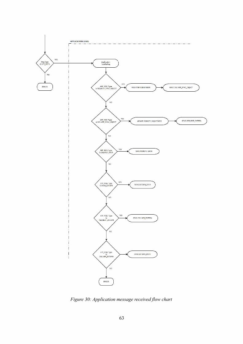
63
Figure 30: Application message received flow chart

4.2.4 Creating and Sharing data items
Creating data items – Data items are created by applications build on top of the MobP2P base system. Ideally all kinds of data should be supported, but the prototype currently only supports data, that can be represented in text form. When a data item has been created the application uses the SyncService handle in the ApplicationService to register a SyncObject. When the SyncObject is created and registered by the SyncService, a nodeId is created for the data item by which it is later identified in the Peer-to-Peer network. Next, the data item is stored by the DataService, from where it can be retrieved later on. This case may occur when the data item has been altered or the application needs access to the data item. Also, an XOR key is created for the data item. Later on, the data item will be encrypted with that key so that the application of the external storage node may not access the data item. Finally, the AuthService encrypts the data item with the key that has been created before and the PushService routes a SAVE_EXTERN message through the Pastry Peer-to-Peer network, containing the encrypted version of the data item. This way the encrypted data item is stored on an external node. Upon arrival of the SAVE_EXTERN message, the SyncService of the external storage node registers the ExternObject and the encrypted data item is stored by the DataService.
Sharing data items – To access another users data item, only the nodeId of the owner and the nodeId of the data item needs to be known. When a remote user has knowledge of these two nodeId, the user may send a REQUEST_SYNC_OBJECT message to the owner node with the nodeId of the data item as content.
When the SyncService receives that REQUEST_SYNC_OBJECT message, it responds by first determining whether such a data item exists. If a SyncObject with the specified nodeId does not exist, the SyncService drops the request and does not answer. Should such a SyncObject exist it responds in two ways. First, the remote prototype's nodeId is entered into a list of subscribers for that data item that is maintained by the DataService. The second response is that the PushService sends a DELIVER_SYNC_OBJECT message to the requesting prototype that does not contain the data item but the key the data item is encrypted with. With that DELIVER_SYNC_OBJECT message the remote prototype also receives an implicit confirmation that a SyncObject with the requested nodeId exists. Upon arrival of the DELIVER_SYNC_OBJECT message, the remote prototype's SyncService registers an empty RemoteObject that is stored by the Dataservice and only contains the key the data item is encrypted with.
The remote prototype may now route a REQUEST_EXTERN message through the Pastry network with the nodeId of the data item as target nodeId. This request will ultimately reach the external storage node of the data item, since the data item is stored on that node that it is numerically closest to. When the prototype of the external storage node receives the REQUEST_EXTERN message it simply responds by sending a DELIVER_DATA message to the remote prototype.
When the remote node receives the DELIVER_DATA message, it uses the DataService to retrieve a RemoteObject with the same nodeId. We mentioned that the key was stored with the empty data item. Using that key the AuthService decrypts the contents of the DELIVER_DATA message. Finally, the SyncService causes the DataService to update the existing RemoteObject with the now decrypted data item and triggers a GUI update notification.
64

Updating data items – Updating data items is similar to sharing data items. We consider the following situation with three devices running the prototype software, of which one is the owner of the data item, a second is a registered subscriber to that data item and the third is the external storage of the data item. In the above paragraph we have considered the situation where the application is notified of changes in a data item by a GUI notification message. In this case, the application build on top of the prototype notifies the SyncService through the handle of the ApplicationService that the user has altered the registered data item. The SyncService of the owner prototype first causes the DataService to update the SyncObject. Next, the SyncService examines the list of subscribers registered to that data item. Each subscriber is notified by a DELIVER_SYNC_OBJECT message send by the PushService of the changes in the data item. Finally, the AuthService encrypts the data item which the PushService sends with a SAVE_EXTERN message to the external storage node.
Now, the registered subscriber receives the DELIVER_SYNC_OBJECT message. As with new RemoteObjects, the actions of the registered subscriber are nearly identical. Before creating a new RemoteObject, the DataService determines if a RemoteObject with the specified nodeId already exists. If no such RemoteObject exists, it creates a new RemoteObject. On the other hand if such a RemoteObject exists, it simply updates the key that is stored with the data item. From now on the actions are exactly the same as described above. The registered subscriber node sends a REQUEST_EXTERN message by which the external storage node responds with a DELIVER_DATA message, that contains the encrypted data item the external storage node received through the SAVE_EXTERN message. The registered subscriber updates the corresponding RemoteObject and the application is notified of changes.
4.3 MobP2P Base System implementation
As mentioned before, the MobP2P base system is packaged into a JAR archive that can be imported by applications. The implementation of the MobP2P base system is divided into three packages as seen in Figure 31. The packages are called Application, Pastry and Data. In the following, we will discuss important classes of these packages and show how they interact.
4.3.1 Pastry configuration values
One of the design goals for the MobP2P prototype is scalability, which means that even with rising numbers of nodes the MobP2P base system should perform well. The testing of the prototype and
65
Figure 31: The three packages of the MobP2P implementation

the example application was performed with a very low numbers of nodes. This was due to the fact that on the development machine only few Android emulators could be run simultaneously. Therefore, we chose Pastry configuration values that were optimized for low node numbers. For future releases of the prototype in environments with high node numbers the Pastry configuration values may be adjusted accordingly.
The Pastry configuration values are defined as static constants in the PastryNode class. They were declared public in order to enable access to these constants throughout the whole project code, as seen in Figure 32.
The Pastry configuration values BASE and L_2 (L/2) are used to determine several aspects. First, they determine the size of the namespace which is BASE to the power of L_2. As mentioned before these values were optimized for extreme low number of nodes. In this case the maximum number of nodes in the network is 256.
The BASE value determines the base of the numeral system that is used for nodeIds. In the case of the prototype nodeIds are binary. The L_2 value configures the number of digits for a nodeId. It also determines how many entries the Pastry state tables hold. The LeafSet and the NeighborhoodSet hold 8 entries each whereas the RoutingTable holds 16 entries.
To optimize the base system for higher numbers nodes only minimal adjustment is necessary. Currently, in the implementation of the NodeID class the Pastry nodeId is represented by a BitSet. Therefore, to alter the numeral base of the nodeIds another data type must be implemented. Then the constants in the PastryNode class can be modified freely.
Another aspect of Pastry configuration is the Pastry proximity metric. As discussed before, there is a wide variety of methods that determine the distance between two nodes. In the prototype there is a basic implementation of using GPS coordinates for a proximity metric. The implementation is available but it has not been tested. For testing purposes, we used in all cases the numerical difference between the nodeIds of two nodes as a proximity metric. For future releases of the prototype the use of GPS coordinates is encouraged especially if the prototype has been deployed on real Android handsets.
4.3.2 Identifying and addressing
In the Pastry protocol nodes are identified addressed by their nodeId. For the implementation of the MobP2P base system the nodeId does suffice for identifying a node but to send a message to a node additional information like IP address or GPS coordinates are required as seen in Figure 33.
We have therefore decided to implement a NodeID class as well as the PastryPeer class that
66
Figure 32: Pastry configuration values

includes a NodeID instance. We will now describe these classes. In the discussion of these classes as well as in their UML diagrams, as seen in Figure 33 we will concentrate on essential fields and methods. We will omit, for example, helper methods like getters or setters and this will also hold true for the discussion of other classes later on in this and the following chapter.
NodeID – The NodeID class holds the BitSet representation of a node's nodeId. The length of the BitSet is determined by the L_2 constant we discussed above. The NodeID class additionally features two methods that are used to compare BitSets of NodeID classes.
The first method is the shl() method that is implemented according to the Pastry specification. The shl() method is given a NodeID instance and determines the number of shared digits of the BitSet with the actual NodeID instance. The number of shared digits is returned as an integer value.
The second method to compare the BitSets of NodeID instances is the numdiff() method. In contrast to the shl() method, the numdiff() method does not consider the shared prefix but the numerical difference of the integer values of the Bitsets. The numdiff() method also returns an integer value that represents the absolute difference of both Bitsets.
PastryPeer – As we will see later, the NodeID class is used as input for the PastryNode's route() method but is not its return value. Instead a PastryPeer instance is returned. The PastryPeer class contains a NodeID instance as well as a string representing the node's IP address, an integer that represents the node's port and a double array that contains the node's GPS coordinates.
The field indicating the port that is used by a node is necessary when the MobP2P prototype is deployed on the Android emulator, as we will see later on. For deployment on real Android handsets the port field may be dropped in favor of a constant that may be declared in the PushService class.
As mentioned before, the double array containing GPS coordinates is currently not used by the prototype, but can be utilized for future versions either by sending GPS coordinates to the Android emulator via DDMS or using the GPS function on real Android devices. In this case, it would be necessary to implement a method that calculates the distance of two pairs of GPS coordinates.
AppMessage – Messages that do not contain content relevant to the Pastry Subsystem are sent in the form of an AppMessage instance. The AppMessage is then pushed by the PushService's push method, where it is transformed into a Pastry level message that is sent by the forward and send
67
Figure 33: Identifying and addressing in the MobP2P prototype

method.
The AppMessage object has two PastryPeer fields representing the sender and the receiver. Since the PastryPeer instances contain the targeted node's nodeId, its IP address and port number no other information is necessary for successful pushing that message. Besides sender and receiver information, the AppMessage has an integer field indicating the message's message type as discussed in Section 4.2.2 and a field that is used to send a data item to another node.
4.3.3 Implementation of the three perspectives of data items
We have discussed the three perspectives of a data item before and will now take a look at how they are implemented as seen in Figure 34. The logical choice for implementing the three perspectives of a data item has been polymorphism.
Our base class is the MobP2PObject with a field for a NodeID instance and an Object instance for the data item. There are three subclasses of the MobP2PObject base class according to the three perspectives of a data item.
ExternObject – The first subclass is the ExternObject class, representing the data item as it is stored on its external storage node. Although it is redundant because it does not contain any fields or methods besides its constructor we decided that it was necessary to provide a seperate implementation for the ExternObject to achieve a uniform representation of the three perspectives concept. The fact that the ExternObject class does not contain any additional information on the owner of the data item is caused by the idea that the external storage node is not supposed to have any access to the data item. If the ExternObject class had such a field, malicious applications on top of the base system could request access to the data item.
RemoteObject – The RemoteObject class is the implementation of the data item from the perspective of the remote node that subscribed to the data item. The second subclass of the
68
Figure 34: The implementation of the three perspectives of a data item

MobP2PObject contains a PastryPeer field for the owner and creator of the data item. Since the remote node that subscribes to a data item may not have or need knowledge of the owners IP address and port, these fields may contain null values. Since all messages concerning data items are routed through the Pastry network at some point, such a message will reach a node that has knowledge of the data item owner's IP address and port. This is true for all nodes that have a state table entry of the data item owner.
The second field of the RemoteObject is a string representation of the key that was used to encrypt the data item. Since in the base system a symmetrical encryption is used, only a single field is necessary for the key as opposed to an asymmetrical encryption.
SyncObject – The SyncObject class is the third subclass of the MobP2PObject class. It is the representation of the data item from the perspective of the owner and creator of the data item. The SyncObject contains PastryPeer type ArrayList, which is used to store the identities of registered users. When the SyncObject has been altered the SyncService uses the contents of that ArrayList to notify registered users of changes in the data item. As the RemoteObject subclass the SyncObject subclass contains a string field containing the key for the symmetrical encryption of the data item.
When a SyncObject instance has been created by the SyncService the createKey() and createNodeID() methods are called. The createNodeID() creates a random NodeID instance that is stored as the SyncObject's NodeID. The createKey() method creates a random key for the XOR encryption and decryption.
4.3.4 Pastry implementation
For the implementation of the Pastry state tables, we decided to create separate classes for each element of the Pastry state tables, as seen in Figure 35.
69
Figure 35: Important classes of the Pastry implementation

Each state table class contains a PastryPeer array. The size of the array is determined by the Pastry configuration values that we have discussed in Section 4.3.1 and that are defined in the PastryNode class. Since messages may be forwarded or send to nodes that represent entries in the state tables, it does not suffice to only store the NodeID instances in the state tables. To forward a message to a node, the IP address of the receiver is needed. With the current version of the base system that is optimized for use on the Android emulator, also the port of the node is required. The implementation of the LeafSet class contains two additional methods. The getLowPeer() and getHighPeer() methods are accessed during the execution of the Pastry routing algorithm. As we recall, the first decision the Pastry routing algorithm makes is whether the target nodeId is numerically within the bounds of the LeafSet. This means that it needs to be determined whether the target nodeId is larger than the smallest entry of the LeafSet and smaller than the largest entry of the LeafSet. To simplify this determination the getLowPeer() and getHighPeer() methods are used.
PastryNode – The key element of the Pastry implementation is the implementation of the Pastry node in the PastryNode class. The PastyrNode class holds with the L_2 and BASE constants two fields that are required as Pastry configuration values. It also contains fields that hold instances of the state table objects. Finally, the instance of a NodeId object that holds the nodeId representing the Pastry node is stored in a field of the PastryNode class. The PastryNode constructor is given a string as an arguments representing an IP address, an integer, indicating a port and a NodeID instance that represent the node's nodeId.
The pastryInit() method may be used for initializing the Pastry network or connecting to an existing Pastry network. Whether to initialize or to connect to a Pastry network is determined by examining the fp (first peer) PastryPeer field of the DataService class. This value may be entered by a user of an application that has been build on top of the MobP2P base system. If the NodeID field of the fp PastryPeer instance is identical to the NodeID field of the node's PastryPeer instance it indicates that no node belonging to an existing Pastry network is known. Therefore, a new Pastry network needs to be initialized. On the other hand if the NodeID is not identical it represents a known node of an existing Pastry network. Consequently, a JOIN message is send to that node, connecting the present node to the Pastry network.
The route() method is the implementation of the Pastry routing algorithm. Given a NodeID instance representing a target nodeId, the route() method returns a PastryPeer instance a message is forwarded to. The route() method accesses the state table instances, as discussed in Section 3.2.2, in order to determine the next hop. Due to the fact that the MobP2P base system was only tested with very low node numbers, situations occurred when the present node's nodeId was numerically closest to the target nodeId and shared the longest common prefix with it. Although the message had not reached its target nodeId, the present node had the nodeId that was closest to it. For these cases we altered the Pastry routing algorithm, so that the route() method returns the PastryPeer representing the present node. Therefore, there is no need to further forward the message and it is delivered to the present node.
Maintaining optimal entries for the state tables is an important task of the PastryNode implementation that is performed by the updateTables() method. The method is given a PastryPeer instance and returns a boolean value indicating whether the given PastryPeer has been entered into the state tables.
Depending on the element of the state table different criteria apply to question whether a PastryPeer instance is entered into the state tables. According to its NodeID instance only a single entry is appropriate for the RoutingTable class.
70

71
Figure 36: Sending Messages with the MobP2P base system

If that entry is empty the PastryPeer instance is automatically entered into that specific entry. Should there already exist a value in that entry both nodeIds are compared and the nodeId that is numerically closest to the present node's nodeId is entered. Values are entered to the LeafSet if the new value is numerically closer to the present node's nodeId and the numerically most distant entry is removed. According to the Pastry protocol, the entries in the NeighborhoodSet represent those nodes that are closest to the present node according to the Pastry proximity metric. Since in the implementation of the prototype numerical distance is used as a proximity metric, the criteria for replacing entries in the NeighborhoodSet are identical to the criteria of the LeafSet.
4.3.5 Messaging
As we have seen in Section 4.2.2, in the MobP2P base system there are two kinds of messages: Application-level messages, that contain content that is relevant to the base system and the application and Pastry-level messages that are used by the Pastry implementation. We will now examine how messages are sent, as seen in Figure 36.
Application-level messages that originate in the SyncService, for example, are represented by the data type AppMessage. As we have seen in Section 4.3.2, the AppMessage type has fields for sender and receiver as well an integer indicating the message type and a MobP2PObject representing a data item. In certain cases, when the data item is not known, for example with an AppMessage with type REQUEST_SYNC_OBJECT, the MobP2PObject only contains a NodeID field and the Object field is left empty. AppMessage instances are passed on to the push() method of the PushService class. The push() method determines the message type and creates a string representation of that AppMessage.
As can be seen in Figure 37, application level messages are wrapped by a Pastry-level message. The structure is TYPE:TO:FROM:APP_LEVEL_TYPE\CONTENT. Application-level messages use the backslash as a delimiter whereas Pastry level messages use a colon. Finally, the push() method calls the route() method to determine the next hop of the message and the string representation together with information of the next hop is passed on to the forward() method.
Pastry-level messages that originate for example in the deliver() or handleMessage() methods of the PushService class are created as a string right from the start. Just like for application-level messages, the creating method also calls the route() method of the PastryNode class to determine the next hop of the Pastry-level message and passes the message including information on the next hop on to the forward() method.
The forward() message is given a PastryPeer instance and a string representation of the message to be sent. It breaks down the PastryPeer instance into a string representing the peer's IP address and the port. As mentioned before, the information about the port used is necessary when testing the
72
Figure 37: String representation of an AppMessage

MobP2P base system on the Android emulator. Finally, the string representation, IP address and port are passed on to the send() method, that is responsible for the actual network connection. We decided to split the sending process into forward() and send() method, because there are Pastry and application-level messages and the forward() method provides a single entry point for both message types.
In the MobP2P base system messages are sent via an UDP network connection from one device to the next with the send() method. The send() method is given a string representation of the message to be sent, the IP address and the port of the next hop. The send method creates a DatagramPacket instance with that information and sends it via a DatagramSocket instance. Before sending the data, the string representation of the message is transformed into a byte array. To ensure that all messages that are sent and received have the same number of bytes, all messages are sent as a byte array with 1024 values. Since not all messages have that length, during the creation of the byte array an end of file identifier is concatenated to the string representation before it is transformed into a byte array and the rest of the array is filled with trailing zeroes. Finally, the DatagramPacket is sent and the DatagramSocket is closed.
73
Figure 38: UML representation of the MobP2P base system Application package

4.3.6 MobP2P API
The main idea behind creating the MobP2P base system, that can be seen in Figure 38, was to create a basis on which a wide variety of applications can be implemented. To achieve this, the applications on top of the base system need access to the base system.
To give applications on top of the base system access to the base system functions, several functions were declared static and public, so they could be accessed from outside the base system without needing a handle to a specific base system element. Table 2 shows a selection of these methods and in the following we will discuss those methods that are most essential. Some of the following functions are currently not accessed from the example application but we envision situations occurring in future applications, where access to the methods could be relevant.
registerSyncObject() – The registerSyncObject() method is used by applications to register a SyncObject instance. The method also initiates the creation of a NodeID instance and an encryption key for the SyncObject. Next, the SyncObject is entered into the SyncObject ArrayList of the DataService class. Finally, the method fires a GUI update message to the generic UpdateGUIListener class and pushes an AppMessage instance with type SAVE_EXTERN using the PushService.
SyncService registerSyncObject()updateSyncObject()registerSubscriber()registerRemoteObject()updateRemoteObject()registerExtern()
PushService push
DataService setMyPeer()setFirstPeer()getSyncObjects()getRemoteObjects()
Table 2: Methods that are accessible to applications on top of the base system
updateSyncObject() – The updateSyncObject() method is called when the SyncObject has been altered by the application's user. The altered SyncObject is updated in the DataService SyncObject ArrayList. A GUI update message is fired, so that the application will display the altered SyncObject correctly. It is also necessary to inform registered subscribers to the SyncObject of its alteration. Therefore, to each registered subscriber a DELIVER_SYNC_OBJECT message is pushed and finally, the method pushes a SAVE_EXTERN message, so that the external storage
74
node now holds the altered version of the SyncObject from where it can be retrieved by its registered subscribers.
registerSubscriber() – The registerSubscriber() method is called when the base system has received a proper REQUEST_SYNC_OBJECT messsage. To answer it a DELIVER_SYNC_OBJECT message is pushed and a PastryPeer containing the nodeId of the registering subscriber is saved in the SyncObjects subscriber PastryPeer type ArrayList.
registerRemoteObject() – The registerRemoteObject() is called when the base system has received a DELIVER_SYNC_OBJECT message. An entry in the DataService's RemoteObject type ArrayList is stored and a REQUEST_EXTERN message is pushed to the external storage node. The RemoteObject entry of the DataService can be later updated when the external storage node has responded with a DELIVER_DATA message.
updateRemoteObject() – The updateRemoteObject() method is called when the external storage node of a data item has responded to a REQUEST_EXTERN message with a DELIVER_DATA message. The information of the RemoteObject is updated in the corresponding entry of the DataService's RemoteObject type ArrayList.
registerExtern() – The registerExtern() message is called by the base system when it has received a SAVE_EXTERN message. The method stores the ExternObject in the DataService's ExternObject type ArrayList.
The registerExtern(), updateRemoteObject(), registerRemoteObject() and registerSubscriber() method are currently not called from the application as mentioned above.
push() – The push() method is used by the PushService class to push messages as described above in Section 4.3.6.
setMyPeer() – The setMyPeer() method is called from the application when its user has entered Pastry initialization data. The users nodeId, IP address and port information is stored in a field of the DataService. This is information can be later accessed by the base system.
setFirstPeer() – The setFirstPeer() method is called from the application when its user has either entered information about a known node that is connected to a Pastry network or the user has chosen an option to start a new Pastry network. If the latter is chosen the firstPeer information that is stored in a field of the DataService class is identical to the myPeer information. If the former is chosen, the information is the later retrieved by the PastryNode instance when it sends its JOIN message.
getSyncObjects(), getRemoteObjects() – The getSyncObjects() and getRemoteObjects() methods are simple getters for the application to access registered data items, most likely used for displaying purposes.
4.3.7 Testing network applications using the Android Emulator
When considering testing applications using the Android Emulator that require network functionality, one must consider that contrary to testing these applications on real Android devices
75

multiple emulators don't have their own IP address by which they may be addressed. Instead it is necessary to make use of the Android Debug Bridge (ADB) and set up a network redirection.
Multiple emulators may address each other using port multiplexing. The ADB forwards network connections according to the redirection that has been set-up, as can be seen in Figure 39.
In this chapter, we presented the MobP2P base system prototype. We started out with discussing its concept, motivation and design goals. In addition, we explained the concept of the base system and its key function to enable users of application built on top of the base system to create and share data items. We discussed the three perspectives of a data item, pastry and application-level message types and message handling that are used for creating and sharing data items. Finally, we took a deeper look at the implementation of the base system and reviewed how nodes and data items are identified addressed, as well as how the Pastry Subsystem was implemented. We concluded with reviewing the MobP2P API and how the Android Debug Bridge can be used to test network applications on the Android emulator.
76
Figure 39: ADB port redirection

5 Example Application
In the following chapter, we will discuss the example application PeerStrings that has been built on top of the MobP2P base system prototype. The goal of the example application is to give a proof of concept showing that it is possible to create applications that may share multiple data items on multiple devices on top of the base system.
5.1 Concept
The design goal for the example application is to create an Android application that accesses the functionality of the MobP2P base system. The application needs to enable users to enter Pastry network relevant data, as well as provide the user the opportunity to create and share data items. To simplify the example application, we decided to use strings as data type for data items, because strings may be easily created and transmitted. Users input strings and request access to strings of other users. The example application then processes the information entered by its users and displays its own string data as well as the string data of other authorized users, as seen in Figure 40. The strings consist of a user name and a user specific message. Both are separated by a delimiter, for which we use the “*” symbol.
5.2 Interaction between base system and example application
The example application interacts with the base system by calling the public static methods we discussed in Section 4.3.6. As we can see in Figure 41, the base system methods called directly from the application are DataService.setMyPeer(), DataService.setFirstContact(), DataService.getSyncObjects, DataService.getRemoteObjects(), PushService.push() and SyncService.registerSyncObject().
77
Figure 40: Sharing multiple Strings on multiple devices

The other form of interaction with the base system is the updateGUIListener interface. The implementation of the updateGUIListener interface is defined inline in the PeerStrings class. The interface defines the fireUpdateGUI() method which is used to inform the example application of changes to the registered data items.
78
Figure 41: Interaction between example application and base system

5.3 Implementation of the example application
The example application is implemented in two packages, the GUI package and the Application package. Furthermore, the MobP2P Jar file is imported, as can be seen in Figure 42. In this chapter, we will discuss the implementation of these two packages and show screen shots that will show its functionality.
5.3.1 Application package
The Application package holds a single class, the PeerStrings class. The PeerStrings class is the implementation of the ApplicationService interface we discussed in Section 4.3.6. The UML representation of the PeerStrings class can be seen in Figure 43. The PeersStrings class has two main functions. The first notifies the GUI of changes to the data items displayed by calling the updateGUI() method. A call to this method will be forwarded to the inline UpdateGUIListener class, who in turn notifies the main Activity DisplayStrings to update the data items it displays.
The second function of the PeerStrings class is to determine if the user has entered all the information that is necessary to initialize the Pastry Subsystem of the MobP2P. Therefore, the PeerStrings class has two boolean fields, the myC and fiC fields. The myC field holds a true value when the user has entered information about its own Pastry node. This information consists of its nodeId, its IP address and its port. The second field fiC, has a true value when the user has entered information about a known Pastry node or opted to start a new Pastry network. Only when both boolean fields hold a true value the dataIsComplete() method returns a true value itself, thereby signaling that all necessary information has been entered by the user. Finally, the init() method is called, which causes the Pastry Subsystem to initialize.
79
Figure 42: Packages of the example application

5.3.2 GUI package
The GUI package consists of five Activities. As we have seen in Section 2.2.5 Activities are user interface components, where each Activity represents a single screen. The layout of an Activity is determined by a corresponding XML Layout file, in which all visual components are defined.
DisplayStrings – The DisplayStrings Activity is the main entry point to the example application, as can be seen in Figure 44. The DisplayStrings Activity has a list layout. The Activiy obtains the entries of that list from the DataService class and displays all registered SyncObjects and RemoteObjects as Strings. These Strings are provided by the private getStrings() method that returns a string array which is used as the list's input. The getStrings() method calls the DataService.getSyncObjects() and DataService.getRemoteObjects() methods and converts the entries of the ArrayLists these methods are returning into Strings array of the format described above.
Furthermore, the DisplayStrings Activity contains a menu, that can be seen in Figure 45 and that is defined in the Activity's OnCreateOptionsMenu() method. The menu holds the entries “Edit Own Peer”, ”Enter Node”, ”Edit Contact” and ”Enter Friend”. When a menu item is selected by the user the OnMenuItemSelected() method determines how that user input is handled. In case of the
80
Figure 43: Implementation of the PeerStrings class

DisplayStrings Activity each menu item selection fires an Intent that causes the corresponding Activity to be displayed. The purpose of these Activities is to give the user the opportunity to enter additional information, like Pastry initialization information, to create data items or to subscribe to a known data item.
When a called Activity terminates, the example application returns to the previously displayed Activity which is in case of the example application always the DisplayStrings Activity. As we mentioned in Section 2.2.5, there are multiple entry points to an Activity. When an Activity is created the entry point is the onCreate() method. When an application returns to a previously displayed activity the entry point is the onResume() method. In case of the DisplayStrings Activity the onResume() method performs a routine call to the PeersStrings dataIsComplete() method to determine if all the relevant information for initializing the Pastry Subsystem has been entered. If this is the case, the init() method of the PeerStrings class is called.
EnterPastryPeer – The EnterPastryPeer Activity, that can be seen in Figure 46, is used to give the user the opportunity to enter information of the user's Pastry node. The Activity has input fields for the users IP adress, the users nodeId and the users port. The IP address input field is preconfigured with the IP address “10.0.2.2”. This IP address is always valid if the example application is run on an Android emulator. For future deployment on real Android devices the user would have to enter his actual IP address.
81
Figure 44: DisplayStrings Activity Figure 45: DisplayStrings Menu

The user confirms his entries by clicking the “Enter” button. When the enter button is clicked, the myC field of the PeerStrings class is toggled to true, the information the user has entered is converted into a PastryPeer instance that is stored by the DataService.setMyPeer() method, and finally the setResult() and finish() methods terminate the Activity and the example application returns to the previously displayed Activity, which is in all cases the DisplayStrings Activity.
EnterNode – The EnterNode Activity, that can be seen in Figure 49, is used to give the user the opportunity to enter information about a known existing Pastry node or to start a new Pastry network. The Activity has three input fields for a known node's IP Adress, a known node's nodeId and the known node's port. The user may also select the menu item “Start a new Pastry network”, that can be seen in Figure 47. In both cases by clicking the “Enter” button the fiC field of the PeersStrings class is toggled to true, the information entered is converted into a PastryPeer instance and stored by the DataService.setFirstPeer() method. Finally, the example application returns to its previously displayed Activity.
EnterContact – The purpose of the EnterContact Activity is to give the user of the example application the opportunity to create or edit a string data item, as can be seen in Figure 48. The Activity has two input fields for user name and message. By clicking the “Enter” button the input of both fields is concatenated and separated by a “*” symbol. Furthermore, the newly created data item
82
Figure 46: EnterPastryPeer Activity Figure 47: EnterNode Activity Menu
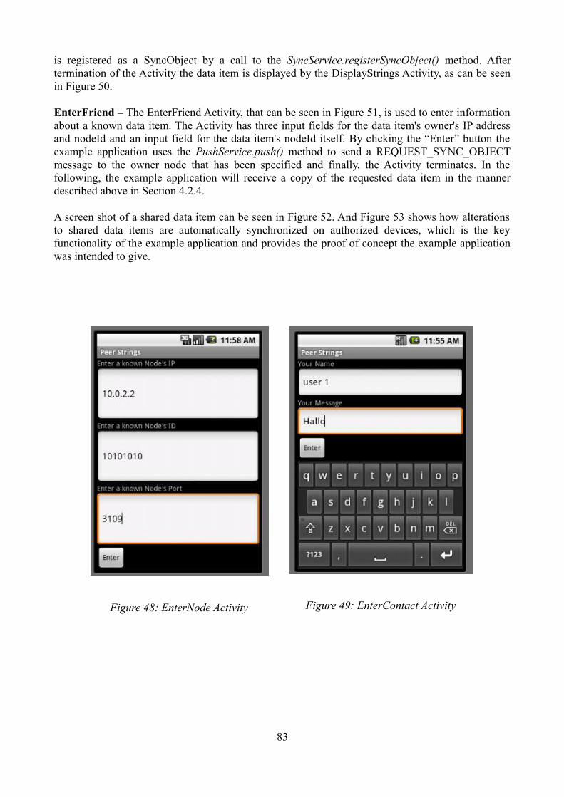
is registered as a SyncObject by a call to the SyncService.registerSyncObject() method. After termination of the Activity the data item is displayed by the DisplayStrings Activity, as can be seen in Figure 50. EnterFriend – The EnterFriend Activity, that can be seen in Figure 51, is used to enter information about a known data item. The Activity has three input fields for the data item's owner's IP address and nodeId and an input field for the data item's nodeId itself. By clicking the “Enter” button the example application uses the PushService.push() method to send a REQUEST_SYNC_OBJECT message to the owner node that has been specified and finally, the Activity terminates. In the following, the example application will receive a copy of the requested data item in the manner described above in Section 4.2.4.
A screen shot of a shared data item can be seen in Figure 52. And Figure 53 shows how alterations to shared data items are automatically synchronized on authorized devices, which is the key functionality of the example application and provides the proof of concept the example application was intended to give.
83
Figure 49: EnterContact ActivityFigure 48: EnterNode Activity

84
Figure 50: DisplayStrings with one entry Figure 51: EnterFriend Activity
Figure 52: Displaying a shared data item on two connected Android emulators

5.4 Possible future applications
In the final part of this chapter, we will discuss what kind of applications could be developed in the future on top of the MobP2P base system. Potentially, a wide variety of applications are possible. For the current version of the software data types for data items would be limited to string based data items, but with some adjustments to the base systems that we will discuss in Chapter 6, these limitations could be overcome.
Shared shopping list – A possible future application could be an application that maintains a shared shopping list, which could be accessed from multiple mobile devices, as can be seen in Figure 54. A user would be able to create a shopping list and share that shopping list with multiple other users. Users could subscribe to share that shopping list by entering an authorization code which would lead to the shopping list being displayed on their devices. By clicking a “new item” button each user could add new items to that shopping list or by selecting a listed item mark it as completed. Changes on the shared shopping list of one user would be automatically synchronized on other authorized devices.
85
Figure 53: Alterations to data items are automatically synchronized on authorized devices

Synchronization of contact information – A further future application could automatically synchronize changes of a users contact information on multiple authorized devices, as can be seen in Figure 55. Since most mobile devices are shipped with a pre-installed contact management software, the described application would have to be able to access that software's data in order to push update notifications. In case of the Android operating system this can be easily done, because the Android contact management software offers a Content Provider by whom all of the user's contact information can be accessed.
Synchronization of calendar information – Another application, that could be created on top of the base system, can be seen in Figure 56, could access a user's calendar data and synchronize that data on multiple devices allowing other users access to that information. If the user owning the calendar would alter a calendar entry, those alterations would be automatically synchronized on all authorized devices.
86
Figure 54: Example of a shared shopping list application
Figure 55: Automatic synchronization of changes to a user's contact data

Shared Notepad – The final possible future application we will present is a shared notepad application. A user could create a notepad on his handset and allow other users to access that notepad. This access of other users could be restricted to reading the notepad or other users could be given the right to alter that notepad.
In this chapter, we discussed the example application that was built on top of the MobP2P base system. We discussed the concept of the example application and how it interacts with the base system. Then, we explained how the example application was implemented. Since the example application consists mainly of Activities which are user interface components, we reviewed the Activities and showed detailed screen shots of how these user interface components were displayed on the Android emulator. In these screen shots we could also show that the example application can successfully be used to synchronize shared data items on multiple devices. Finally, we presented an overview of possible application that could be implemented in the future.
87
Figure 56: Automatic synchronization of changes to a users calendar data

6 Conclusion
6.1 Summary
The thesis started out by showing the motivation that could lead to develop Peer-to-Peer based software for mobile handsets. We continued, giving an overview over existing smartphone platforms and compared them according to a fixed set of characteristics. We described the Android platform in greater detail, discussing Android platform tools, the Dalvik VM, the Android SDK and Android NDK. We showed how these tools function and interact and reviewed Android application components and how they are used to build Android applications.
Next, we presented an overview on common second generation Peer-to-Peer protocols like CAN and Chord. We further discussed the Pastry protocol in greater detail, showed how its routing algorithm worked and why Pastry may claim good route locality. We continued by presenting systems that were built on top of the Pastry protocol and then discussed security concerns for overlay networks, that might be averted by secure nodeId assignment, secure routing table maintenance and secure message forwarding.
In the following, we presented the MobP2P prototype consisting of the base system and an example application built on top of it. The prototype was developed for the Android platform and tested on an Android emulator. We showed, that the base system can be used share multiple data items on multiple mobile devices. We presented the concept and design goals behind the MobP2P base system and discussed its system architecture, the three perspectives of a data item and how Pastry and application-level message types may be used to synchronize shared data items. Finally, we showed that the example application built on top of the base system can be successfully used to synchronize string data items on multiple devices.
6.2 Future workIn the following we will discuss how the MobP2P base system could be improved in the future. Also we will review several issues that could not be resolved in the current implementation of the base system.
Node Failure – In the current version of the MobP2P base system a possible node failure is not handled. The Pastry protocol treats this problem by periodically contacting the nodes from the NeighborhoodSet. If a node should not respond, the calling node would try to fix the entries in its state tables by contacting other nodes in its NeighborhoodSet. While implementing the base system, we unsuccessfully implemented this strategy in a Thread that would sleep for a specified time and then sent messages to the nodes in its NeighborhoodSet. We encountered the problem that during the sleep phases of the Thread, the whole system was blocked and the rest of the application remained unresponsive, which means the application was blocked most of the time. This behavior might be avoided by implementing the periodical messages not in a Thread but as an Android Service.
Object Serialization – To enable the base system to deal with data types more complex than strings
88

we implemented a small helper program for testing object serialization. We first compiled the program with the Java JSE compiler and ran it in in a JSE virtual machine. With the helper program we successfully transformed a test object that implemented the java.io.Serializable interface into a byte array using a ByteArrayOutputStream. Furthermore, the test object was successfully reassembled. Since java.io is part of the Android SDK libraries we implemented an analogue program using the Android SDK and ran it in the Dalvik VM on the Android Emulator. This attempt was unsuccessful. As we learned later, object serialization works on Android successfully out of the box only for native data types, but not for objects created by a user. For this reason, we chose to limit the example application to string based data types. To enable the base system to deal with more complex data types the data-interchange format JSON [45] could be deployed in order to convert complex data types into a string like format. Another strategy could be overwriting the writeObject() and readObject() methods for classes that implemented the java.io.Serializable interface.
DataService as SQLite Database – In the current version of the base system, the DataService class stores data simply at run time in variables. For a proper deployment of the base system the DataService class should store data in a SQLite database instead. This would simplify the example application considerably since information like data concerning the Pastry initialization would only need to be entered once. We would prefer an SQLite Database over a configuration file, because the DataService class not only holds configuration data but is also used to store the data items created by the application's user.
AuthService – The current version of the base system encrypts messages with an XOR encryption. For a proper deployment an adequate encryption algorithm should be used. An asymmetrical encryption algorithm would also require some kind of encryption key management and exchange strategy.
AppServer as Service – Currently, the AppServer is implemented as a Thread. This was done to simplify the base system. Future versions could implement the AppServer as an Android Service instead of a Thread. The difference between a Service and a Thread is that the Service runs indefinitely in the background whereas a Thread would be terminated when the user terminates the application that started it. The advantage of that strategy would be that a user could be notified of relevant events without the need of having the application running. In case of an event like an incoming message, the Service could send an untargeted intent for which the application would declare an appropriate intent-filter which would lead to the application being started and handling that event.
Finally, to make better use of Pastry's locality properties, future versions of the base system could decide on a different proximity metric, since in the current implementation numerical difference is used as a proximity metric. Also, by implementing the base system for various smartphone platforms, applications built for the base system could gain a wider user acceptance if the technology would not be limited to the Android platform.
In conclusion, there are still areas in which to improve the software presented, but the key functionality of sharing data items on multiple devices and the automatic synchronization of these data items has been realized successfully.
89

Bibliography
[1] “ipoque Internet-Studie 2007: P2P-Filesharing dominiert weiterhin das Internet weltweit”, ipoque web site, retrieved on: 20.6.2010, URL: http://www.ipoque.com/news-and-events/news/ipoque-internetstudie-2007-p2pfilesharing-dominiert-weiterhin-das-internet-weltweit.html
[2] A. Oram, “Harnessing the Power of Disuptive Technologies”, O’Reilly, Sebastopol/CA,
USA, 2001
[3] R. Steinmetz, K. Wehrle, “Peer-to-Peer-Networking & -Computing”, Aktuelles Schlagwort, Informatik Spektrum 27(1), pp. 51-54, 2004
[4] “The Annotated Gnutella Protocol Specification v0.4”, Gnutella web site, retrieved on: 20.6.2010, URL: http://rfc-gnutella.sourceforge.net/developer/stable/index.html
[5] “Kazaa - The FastTrack Protocol” , Wikipedia, retrieved on: 20.6.2010, URL: http://en.wikipedia.org/wiki/FastTrack
[6] S. Ratnasamy, P. Francis, M. Handley, R. Karp, S. Shenker: "A Scalable Content-Addressable Network", in Proc. of ACM SIGCOMM'01, San Diego, CA, USA, August 2001
[7] A. Rowstron, P. Druschel: "Pastry: Scalable, Distributed Object Location and Routing for Large-scale Peer-to-Peer Systems", in Proc. of ACM/IFIP Middleware, Heidelberg, Germany, November 2001
[8] I. Stoica, R. Morris, D. Karger, M. F. Kaashoek, and H. Balakrishnan: "Chord: A Scalable Peer-to-peer Lookup Service for Internet Applications", in Proc. of ACM SIGCOMM'01, San Diego, CA, USA, August 2001
[9] T. Zahn, “Structured Peer-to-Peer Services for Mobile Ad Hoc Networks”, Dissertation, Freie Universität Berlin, Berlin, Germany, July 2006
[10] “Napster”, Wikipedia, retrieved on: 20.6.2010, URL: http://en.wikipedia.org/wiki/Napster
[11] “Gartner Highlights Key Predictions for IT Organizations and Users in 2010 and Beyond”, Gartner Newsroom, retrieved on: 20.6.2010, URL: http://www.gartner.com/it/page.jsp?id=1278413
[12] “Open Handset Alliance”, Open Handset Alliance, retrieved on: 20.6..2010, URL:
90

http://www.openhandsetalliance.com/
[13] “Nokia Communicator 9000”, GSM Arena, retrieved on: 20.6.2010, URL: http://www.gsmarena.com/nokia_9000_communicator-16.php
[14] “ Nexus One”, Google, retrieved on 20.6.2010, URL: http://www.google.com/phone/
[15] “MWC: Smartphones erobern den Massenmarkt”, Heise, retrieved on: 20.6.2010, URL: http://www.heise.de/newsticker/meldung/MWC-Smartphones-erobern-den-Massenmarkt-927964.html
[16] B. Xu, O. Wolfson, “Data Management in Mobile Peer-to-Peer Networks”, in Proc. DBISP2P, pp. 1–15, 2004
[17] E. Harjula, M. Ylianttila, J. Ala-Kurikka, J. Riekki, J. Sauvola, “Plug-and-Play Application Platform: Towards Mobile Peer-to-Peer”, Proceedings of the 3rd international conference on Mobile and ubiquitous multimedia, pp. 63-69, College Park, Maryland, USA, October 2004
[18] F. H. P. Fitzek, H. Charaf, “Mobile Peer to Peer (P2P): A Tutorial Guide”, John Wiley & Sons, 2009
[19] “App Store”, Wikipedia, retrieved on 20.6.2010, URL: http://de.wikipedia.org/wiki/App_Store
[20] Gartner, Mobile Web Trends 2007 to 2011. Research Report, June 2007
[21] V. Roto, E. Kaasinen, “The Second International Workshop on Mobile Internet User Experience”, Mobile HCI 2008: pp. 571-573
[22] “Gartner Says Touchscreen Mobile Device Sales Will Grow 97 Percent in 2010”, Gartner Newsroom, retrieved on 20.6.2010, URL: http://www.gartner.com/it/page.jsp?id=1313415
[23] “ADC I Top 50 Gallery”, Google, retrieved on : 20.6.2010, URL: http://code.google.com/intl/de-DE/android/adc/adc_gallery/
[24] M. Bergner, “Improving Performance of Modern Peer-to-Peer Services”, Master’s thesis, UMEA 28 University, Department of Computer Science, 2003
[25] S. Hall, E. Anderson, “Operating Systems for Mobile Computing”, Consortium of Computing Sciencies in Colleges, 2009
91

[26] I. Clarke, O. Sandberg, B. Wiley, T. W. Hong, ”Freenet: A Distributed Anonymous Information Storage and Retrieval System”, in Proceedings of the ICSI Workshop on Design Issues in Anonymity and Unobservability, Berkeley, California, USA, June 2000
[27] T. Zahn, J.H. Schiller, “MADPastry: A DHT Substrate for Practicably Sized MANETs”, 5th Workshop on Applications and Services in Wireless Networks (ASWN2005), 2005
[28] A. Rowstron, A.-M. Kermarrec, P. Druschel, M. Castro, “SCRIBE: The Design of a large-scale Event Notification Infrastructure,” in Proceedings of NGC, pp. 30–43.London, UK, November 2001
[29] M. Castro, P. Druschel, A. Ganesh, A. Rowstron, D. S. Wallach, “Secure Routing for Structured Peer-to-Peer Overlay Networks,” in Proceeding of OSDI, pp. 299–314, Boston, MA, , USA, December 2002
[30] B. Y. Zhao, J. D. Kubiatowicz, A. D. Joseph, “Tapestry: An Infrastructure for Fault-Resilient Wide-Area Location and Routing”, Technical Report UCB//CSD-01-1141, U. C. Berkeley, USA, April 2001
[31] C. E. Perkins, E. M. Royer, S. Das, “ Ad-hoc on Demand Distance Vector (AODV) Routing”, RFC 3561, July 2003.
[32] C. G. Plaxton, R. Rajaraman, A. W. Richa, “Accessing Nearby Copies of Replicated Objects in a Distributed Environment,” in Proceedings of SPAA, , pp. 311–320, Newport, RI, June 1997
[33] “Palm Developer Center”, Palm web site, retrieved on: 20.6.2010, URL: http://developer.palm.com/index.php
[34] “MeeGo”, MeeGo web site, retrieved on: 20.6.2010, URL: http://meego.com/
[35] “The Home of the Maemo Community”, Maemo web site, retrieved on: 20.6.2010, URL : http://maemo.org/intro/
[36] “Create the Mobile Internet Future”, MobLin web site, retrieved on: 20.6.2010, URL: http://moblin.org/
[37] “Bada”, Bada web site, retrieved on: 20.6.2010, URL: http://www.bada.com/
[38] “Openmoko - Open. Mobile. Free. ”, openmoko wiki, retrieved on: 20.6.2010, URL:
92

http://wiki.openmoko.org/wiki/Main_Page
[39] “Blackberry Developer Zone”, Blackberry web site, retrieved on: 20.6.2010, URL: http://de.blackberry.com/developers/
[40] “Windows Phone”, Windows Phone 7 web site, retrieved on: 20.6.2010, URL: http://www.windowsphone7.com/
[41] “Symbian Developer”, Symbian website, retrieved on 20.6.2010, URL: http://developer.symbian.org/
[42] “Developing On A Device”, Android Developers, retrieved on: 20.6.2010, URL: http://developer.android.com/guide/developing/device.html
[43] “The Android NDK”, Android Developers, retrieved on: 20.6.2010, URL: http://developer.android.com/sdk/ndk/index.html
[44] “Android SDK”, Android Developes, retrieved on: 20.6.2010, URL: http://developer.android.com/sdk/index.html
[45] “JSON”, JSON web site, retrieved on:20.6.2010, URL: http://www.json.org/
[46] M. Weiser, “The Computer for the 21st Century”, retrieved on 20.6.2010, URL: http://www.ubiq.com/hypertext/weiser/SciAmDraft3.html,
[47] T. O'Reilly, "What Is Web 2.0",. O'Reilly Network, retrieved on: 20.6.2010, URL: http://www.oreillynet.com/pub/a/oreilly/tim/news/2005/09/30/what-is-web-20.html
[48] “Android”, Android web site, retrieved on: 20.6.2010, URL: http://www.android.com
[49] “LiMo Foundation”, LiMo Foundation web site, retrieved on: 20.6.2010, URL: http://www.limofoundation.org/
[50] “comScore Reports January 2010 U.S. Mobile Subscriber Market Share”, comScore, retrieved on 20.6.2010, URL: http://www.comscore.com/Press_Events/Press_Releases/2010/3/comScore_Reports_January_2010_U.S._Mobile_Subscriber_Market_Share
[51] “Gartner Says Worldwide Smartphone Sales Grew 16 Per Cent in Second Quarter of 2008”,
93
Gartner Newsroom, retrieved on: 20.6.2010, URL: http://www.gartner.com/it/page.jsp?id=754112
[52] “Lots of Samsung bada OS screenshots leaked”, DriversDown News, retrieved on 20.6.2010, URL: http://news.driversdown.com/mobile/200912/18-21736.html
[53] “BlackBerry Bold: the DEFINITIVE hands-on review”, APC, retrieved on: 20.6.2010. URL:
http://apcmag.com/Content.aspx?id=2783&viewall=1
[54] “Erster Eindruck: Google-Smartphone G1 mit Minitastatur”, travelmobility.ch, retrieved on: 20.6.2010, URL: http://www.travelmobility.ch/2008/09/erster-eindruck-google-smartphone-g1.html
[55] “A Ring To Unite Them All”, Symbian-Life Blog, retrieved on: 20.6.2010, URL:
http://symbian-lifeblog.com/tag/htc
[56] “Vodafone 360 Samsung M1”, handysmobile.de, retrieved on 20.6.2010, URL:
http://www.handys-mobile.de/vodafone-360-samsung-m1-kundenbewertung.html
[57] ”Maemo OS Mobile Application Development Service”, AndroidBoss, retrieved on 20.6.2010,
URL: http://androidboss.com/tag/internet-tablet/
[58] “Official MeeGo UI Screenshots and Videos emerge”, ZOMGITSCJ, retrieved on: 20.6.2010,
URL: http://zomgitscj.com/official-meego-ui-screenshots-and-videos-emerge/
[59] “Moblin v2.1 Looks Good”, Trusted Reviews, retrieved on: 20.6.2010, URL: http://www.trustedreviews.com/cpu-memory/news/2009/09/23/Moblin-v2-1-Looks-Good/p1
[60] “OpenMoko FreeRunner Linux Cellular Phone”, PaulTech Network, retrieved on: 20.6.2010,
URL: http://gopaultech.com/blog/2008/01/openmoko-freerunner-linux-cellular-phone/
[61] “Symbian S60 5th edition rolls out”, Nokia Conversations, retrieved on: 20.6.2010, URL: http://conversations.nokia.com/2008/10/02/symbian-s60-5th-edition-rolls-out/
[62] “Palm Pre UI Overview”, Design for the User, retrieved on: 20.6.2010, URL: http://www.designfortheuser.com/uxd/2009/06/10/palm-pre-ui-overview/
[63] “Windows Phone 7 Series: An diese Vorgaben müssen sich die Hersteller halten!”, DonRivas.ch, retrieved on: 20.6.2010, URL: http://www.donrivas.ch/2010/02/24/windows-phone-7-
94

series-an-diese-vorgaben-mussen-sich-die-hersteller-halten/
[Patent] Georg Wittenburg, “Erfindungsbeschreibung 'Verfahren zur kollaborativen Datenverarbeitung auf mobilen Endgeräten'”, Berlin, December 2008
95

List of Figures
Figure 1: Overlay Hop vs Internet Hop..............................................................................................14Figure 2: Peer-to-Peer Architecture vs Client Server Architecture....................................................15Figure 3: System Overview................................................................................................................17Figure 4: Web OS User Interface [62]................................................................................................19Figure 5: Screenshot of the Maemo User Interface [57]....................................................................20Figure 6: Intel MobLin User Interface [59]........................................................................................21Figure 7: Screenshots of the handheld version of the MeeGo UI [58]...............................................22Figure 8: Image of the Vodafone 360 M1 and the LiMo User Interface [56]....................................23Figure 9: A Screenshot of the Bada UI as seen on the Samsung Wave [52]......................................24Figure 10: Image of the OpenMoko Freerunner [60].........................................................................25Figure 11: The User Interface of Windows Phone 7 [63]...................................................................26Figure 12: User Interface of the Blackberry Device Software [53]...................................................27Figure 13: The Symbian S60 User Interface of the Symbian^3 OS [61]...........................................28Figure 14: User Interface of iPhone OS [55]......................................................................................29Figure 15: Image of the Google G1 smartphone [54]........................................................................30Figure 16: Collaboration of Android Tools........................................................................................32Figure 17: Pastry's routing algorithm [7]............................................................................................41Figure 18: Example of Pastry state tables.[7].....................................................................................42Figure 19: Experimental Results of the Pastry Routing Algorithm....................................................45Figure 20: An example of a typical WAP page compared to the browser on a current Android smartphone ........................................................................................................................................50Figure 21: Storing data on and processing data through a Peer-to-Peer network of mobile devices instead of a central server instance.....................................................................................................51Figure 22: Shared data items are automatically synchronized on multiple authorized devices.........52Figure 23: MobP2P base system architecture.....................................................................................53Figure 24: The three perspectives of a data item................................................................................54Figure 25: Overview of MobP2P message types and usage...............................................................57Figure 26: Data retrieval via an external storage node.......................................................................58Figure 27: Handover of external storage responsibility. In this case |0101 - 0100| < |0111 - 0100|. Therefore node 2 is the new external storage node for the data item.................................................59Figure 28: Routine check whether a message type is JOIN...............................................................60Figure 29: Message received flow chart.............................................................................................62Figure 30: Application message received flow chart..........................................................................63Figure 31: The three packages of the MobP2P implementation.........................................................65Figure 32: Pastry configuration values...............................................................................................66Figure 33: Identifying and addressing in the MobP2P prototype.......................................................67Figure 34: The implementation of the three perspectives of a data item...........................................68Figure 35: Important classes of the Pastry implementation...............................................................69Figure 36: Sending Messages with the MobP2P base system............................................................71Figure 37: String representation of an AppMessage..........................................................................72Figure 38: UML representation of the MobP2P base system Application package...........................73Figure 39: ADB port redirection.........................................................................................................76Figure 40: Sharing multiple Strings on multiple devices...................................................................77Figure 41: Interaction between example application and base system...............................................78Figure 42: Packages of the example application................................................................................79Figure 43: Implementation of the PeerStrings class...........................................................................80
96
Figure 44: DisplayStrings Activity.....................................................................................................81Figure 45: DisplayStrings Menu........................................................................................................81Figure 46: EnterPastryPeer Activity...................................................................................................82Figure 47: EnterNode Activity Menu.................................................................................................82Figure 48: EnterNode Activity...........................................................................................................83Figure 49: EnterContact Activity........................................................................................................83Figure 50: DisplayStrings with one entry...........................................................................................84Figure 51: EnterFriend Activity..........................................................................................................84Figure 52: Displaying a shared data item on two connected Android emulators...............................84Figure 53: Alterations to data items are automatically synchronized on authorized devices.............85Figure 54: Example of a shared shopping list application.................................................................86Figure 55: Automatic synchronization of changes to a user's contact data........................................86Figure 56: Automatic synchronization of changes to a users calendar data.......................................87
97
List of Tables
Table 1: Comparison between Nexus One and Nokia Communicator...............................................12Table 2: Methods that are accessible to applications on top of the base system................................74
98

Erklärung
Hiermit versichere ich, dass ich die vorliegende Arbeit selbständig angefertigt habe und ohne fremde Hilfe verfasst habe, keine außer den von mir angegebenen Hilfsmittel und Quellen dazu verwendet habe und die den benutzten Werken inhaltlich oder wörtlich entnommenen Stellen als solche kenntlich gemacht habe
Berlin, den 29. Juni 2010
Jan Kettner
99