colibrinano - radioamateur.org · operating the colibrinano receiver and enjoy a modern way of...
TRANSCRIPT

Expert Electronics
2017
ColibriNANO Direct Sampling HF/6M receiver
User Manual V1.1

2 Expert Electronics
2017
1. Introduction ...................................................................................................................... 4
2. ExpertSDR2 Software License Agreement ...................................................................... 4
3. Technical characteristics .................................................................................................. 5
4. Hardware description ....................................................................................................... 6
5. Connect the ColibriNANO to a PC ................................................................................... 8
6. Local operation ................................................................................................................ 9
7. Remote operation .......................................................................................................... 10
8. ExpertSDR2 Software Description ................................................................................. 11
8.1. Global controls panel .................................................................................................. 11
8.2. Software receiver settings ........................................................................................... 13
8.2.1. Receiver control panel ............................................................................................. 13
8.2.2. Frequency and S-meter indicators ........................................................................... 16
8.2.3. DSP control panel .................................................................................................... 18
8.2.4. Panoramic Display description ................................................................................. 21
8.2.4.1. Spectrum Scope ................................................................................................... 21
8.2.4.1.1. Spectrum Scope scaling .................................................................................... 22
8.2.4.1.2. Frequency tuning ............................................................................................... 23
8.2.4.2. Waterfall ................................................................................................................ 24
8.3. Status bar.................................................................................................................... 24
9. ExpertSDR2 software fine tuning ................................................................................... 25
9.1. Device menu ............................................................................................................... 25
9.1.1. Device settings ......................................................................................................... 25
9.1.2. VAC tab.................................................................................................................... 26
9.1.3. DSP tab.................................................................................................................... 26
9.1.4. Expert tab ................................................................................................................. 29
9.2. Sound card menu ........................................................................................................ 30
9.2.1. Sound card ............................................................................................................... 30
9.2.2. Line output ............................................................................................................... 31
9.3. Display menu .............................................................................................................. 31
9.3.1. Main window tab ...................................................................................................... 32
9.3.2. Spectrum tab ............................................................................................................ 33
9.3.3. Waterfall tab ............................................................................................................. 36
9.3.4. Grid tab .................................................................................................................... 37
9.3.5. Filter tab ................................................................................................................... 37
9.3.6. Background tab ........................................................................................................ 38
9.4. САТ menu ................................................................................................................... 39
9.5. Panel menu ................................................................................................................. 41
9.6. Features menu ............................................................................................................ 45

3 Expert Electronics
2017
9.7. ExpertSync menu ........................................................................................................ 46
9.8. CW Skimmer menu ..................................................................................................... 47
9.9. Shortcuts menu ........................................................................................................... 48
9.10. IQ Recorder menu .................................................................................................... 49
9.11. TCI menu .................................................................................................................. 49
9.12. Spot settings menu ................................................................................................... 50

4 Expert Electronics
2017
1. Introduction
If you’ll spend just 30 - 45 minutes to read this manual, you will be able to easily begin
operating the ColibriNANO receiver and enjoy a modern way of listening the air. This manual
will answer most of your questions.
Quick and efficient mastering of the ColibriNANO receiver requires a basic PC knowledge.
We hope that the Windows terms, which are used in this guide are familiar to the user and
won’t cause any difficulties. To make this manual more user-friendly, we used screenshots
of dialogue windows; necessary functions are highlighted with colored contour.
Since the ColibriNANO is an SDR, it means that you will need a PC or laptop to use the
receiver. You can control your receiver with the ExpertSDR2, HDSDR or SDRSharp software
installed on your PC. The main features of this receiver are the 14-bit ADC @ 122.88 MHz,
Blocking Dynamic Range (BDR): 110 dB and sensitivity: 0.35 uV.
There is no signal processing path, in its classical meaning, in this receiver. The signal is
digitized from the antenna and all the other signal processing happens in the software.
2. ExpertSDR2 Software License Agreement
ExpertSDR2 software is the proprietary product and intellectual property of Expert
Electronics. It is forbidden to modify, copy or disclose to third parties ExpertSDR2 software
distribution.
Official versions of the software are published on the manufacturers website in section
"ColibriDDC receiver / Downloads".
New versions of the ColibriDDC receiver software may have different titles from time to time.
This license agreement applies to all new versions of the software and may be supplemented
and / or amended unilaterally by Expert Electronics.
The manufacturer reserves the right to alter and / or improve the ColibriDDC receiver
software, adding new features and bug fixes. In this regard, the software may be different
from the description herein. Ask your closest dealer on the availability of new, more complete
version of the User Manual, or look for them on the official website of the manufacturer in
the section "ColibriDDC receiver / Documentation".
Users of the ColibriDDC receiver can update the software by themselves, by downloading
from the official website of the Expert Electronics company.
The manufacturer is not responsible for the consequences of the user utilizing an unofficial
or modified version of ExpertSDR2 software and/or changes the settings or other files which
are related to the ExpertSDR2 functionality.
The manufacturer assumes no responsibility for the material, moral or any other kind of
damage, whether expressed or implied, caused by using of a third-party software.

5 Expert Electronics
2017
The manufacturer assumes no responsibility for the material, moral or any other kind of
damage, whether expressed or implied, caused by using of external devices along with the
ColibriDDC receiver.
3. Technical characteristics
Modes LSB/USB/DSB/CW/AM/SAM/NFM/WFM
Receiving bandwidth, MHz 0.01 - 55
Receiving bandwidth in the undersampling mode,
MHz 0.01– 500
Noise floor, dBm
1.9 MHz (160M) - 131
7.1 MHz (40M) - 130
52.5 MHz (6M) - 127
Sample rate with IQ stream resolution 24-bit, kHz 48, 96, 192, 384, 768
Sample rate with IQ stream resolution 16-bit, kHz 1536, 1920, 2560, 3072
Amount of software receivers 1 (+1 SubRX)
Sensitivity, uV 0.35
Blocking Dynamic Range (BDR), dB 110
IMD3 Dynamic Range, dB 95
Supply voltage range, V 4.5...5.5
Maximum antenna input voltage, without ADC
overload, mV (ATT=0 dB) 74 (Pk-Pk); 32.7 (RMS)
Maximum current consumption, A 0.41
Input impedance, Ohm 50
ADC clock frequency, MHz 122.88
ADC resolution, bit 14
Local oscillator stability, ppm +/- 0.5
Local attenuator with 0.5 dB step, dB from -31.5 up to +6
RF input with up to 15 kV ESD protection SMA connector
Dimensions L x W x H, mm (inches) 90х25х17 (3 1/2" x 1" x 5/8")
Operating temperature, °C (°F) from -10 up to +60 (14…140)
Weight, gram (ounces) 43 (1.52)

6 Expert Electronics
2017
4. Hardware description
ColibriNANO block diagram
Architecture description
Receive path consists of the following functional units:
Ant – antenna connector.
LPF – Low Pass Filter with 55 MHz bandwidth. This filter allows you to receive signals
in the first Nyquist zone and eliminates signals from the second Nyquist zone. It switches
ON/OFF automatically according to the panorama center, ON - inside the 0-55 MHz range
and OFF – above 55 MHz.
ATT - attenuator -31.5…0 dB with 0.5 dB step, it allows to “weaken” signals to eliminate
the receiver overload while receiving strong signals.
Driver – it’s purpose is to amplify the signal and transfer it to the ADC.
Preamp – preamplifier 0…+6 dB, it can additionally amplify signals.
TCXO – Temperature-Compensated Crystal Oscillator with 122.88 MHz frequency.
This is a high-stability oscillator with temperature instability 0.5 ppm.
ADC – high-speed Analog-to-Digital Converter with 14-bit resolution and 122.88 MHz
sample rate. ADC is the heart of the receiver; it is responsible for direct sampling of all signals
in the 55 MHz bandwidth.
FPGA – Field Programmable Gate Array. It makes all high-speed processing
operations. Inside the FPGA happens the first down conversion of signals. It is similar with
the first converter in a classic super-heterodyne, but all operations processed in a
mathematic order with binary logic.

7 Expert Electronics
2017
Controller – It controls all ColibriNANO systems and performs the data exchange
between the receiver and the USB controller.
USB FT232H – It performs the data exchange between the Controller and a PC.

8 Expert Electronics
2017
5. Connect the ColibriNANO to a PC
To operate the ColibriNANO receiver you’ll need:
Personal computer. Recommended characteristics:
2х or 4х core CPU - Intel Core i3, i5, i7 or equal AMD processor; software can work on
“weaker” CPU like Core2Duo or Dual-Core, but it may lead to an exceeding CPU load.
4 GB RAM;
40 GB free space on your HDD/SSD;
15…27-inch monitor;
Video card which supports OpenGL 1.5 or higher.
Antenna, tuned on the HAM bands, should have impedance around 50 Ohm for those
bands, where you plan to operate.
Supported operating system: Windows 7-10 32/64 bit. The latter the better.
Check your version of the Microsoft Visual C++ (click the right mouse button on the Windows
Start button-> Programs and Features), before installation of the ExpertSDR2 software, if
your installed version is above the one offered during installation, select "cancel".
When you plug the ColibriNANO in your PC, Windows will automatically download required
USB driver (ensure PC is connected to the internet before connecting the ColibriNANO).
Then receiver will be detected by Windows as new device, that’s all, you may use the
ColibriNANO.
If Windows will not automatically download required USB driver, download drivers from one
of the links below and manually assign them to the undetected device in the Device Manager
menu. Dismiss Windows warning regarding unsigned software and proceed with the
installation.
CDM v2.12.26 WHQL Certified x64 for 64-bit PC
CDM v2.12.26 WHQL Certified x86 for 32-bit PC
Official driver installation guides for:
Windows 7
Windows 8
Windows 10

9 Expert Electronics
2017
6. Local operation
Local operation is a standard way to use the ColibriNANO receiver. Make the following
connections as described below:
1. Plug the ColibriNANO in your PC;
2. Connect HF-antenna to the receiver antenna connector;
3. Open "Options” menu and ensure "device connected" is displayed. If not, get correct
driver.
4. Start the ExpertSDR2 software with the red Start button (left top corner of the software
window);
5. Open Options→ Sound Card menu
and make sure that the Enable checkbox in
the Sound card block is set. See picture;
6. Click OK. If everything is done correctly, you will see the air noise on the panorama and
hear the sound in the headphones.

10 Expert Electronics
2017
7. Remote operation
To control the ColibriNANO via Internet we created the ExpertRemote system, based on the
client-server connection. This system allows you to place the receiver and server in the
remote location with low air noise and Internet connection. This might be some remote
village or place with no electrical interference and 3G/4G Internet (or any other connection
type). Using the ExpertRemote system you can enjoy clear air from your phone, tablet,
notebook or PC. Even simple antennas, placed in a "quiet" place, allows you to listen to the
far stations with low level.
Another feature of this system is that the receiver's software can be synchronized with
transceivers and be used as the panorama adapter with high resolution. Use the transceiver
to transmit signals, receive on your remotely located receiver via the ExpertRemote system.
Distant stations, rare (DX) stations or expeditions from now on will be a reality for you with
our ExpertRemote system!
More information about the ExpertRemote system you can find here.
ExpertRemote system block-diagram

11 Expert Electronics
2017
8. ExpertSDR2 Software Description
Software settings which won't be mentioned or addressed in this manual, are set by default
or provided to the user's self-study and experiments. All the unmentioned settings cannot
cause the fatal damage of the ColibriNANO receiver hardware, so you can safely experiment
with them. You're dealing with the software-defined radio – SDR, the main settings and signal
processing is held in the software.
8.1. Global controls panel
This panel consists of the following buttons:
- the Start button switches on/off the ExpertSDR2 software.
Attenuator level can be set in the drop down menu with a slider (0.5
dB step) or by successive presses of the indicator button, which
cycles upwards the attenuation coefficient with 5 db step, from -30dB
up to +5 dB.
- enable/disable button of the sound output from the PC's sound card.
- enable/disable button of the frequency memory panel.

12 Expert Electronics
2017
- Volume slider. This setting affects the LF output volume
on the PC's sound card. Speaker icon has the mute function.
- in the Profile manager menu you can:
add a new profile, by entering the name of the profile in the “Profile name” field and
pressing Add button.
set the settings of the whole program to the default state, by the Default button.
Update the settings of the certain profile from the list to the current settings.
Remove the certain profile from the list.
Note! All new profiles will be stacked up to the drop-down menu as a new line.
- Options menu will be fully described later in the Paragraph#9 of the manual.
- About button opens the new window with the info about current version of the
ExpertSDR2 software:
- pressing the Fullscreen mode button will unfold the software window on the whole
screen.

13 Expert Electronics
2017
8.2. Software receiver settings
These settings are divided in four logical parts:
8.2.1. Receiver control panel
- volume and balance control menu for the first and second receivers separately.
- button opens an 18-band equalizer menu.
Equalizer has an indicator below the VFO A frequency
tab (enabled on the picture).

14 Expert Electronics
2017
- button enables the VAC (data exchange via virtual audio cables).
- button enables the squelch. Displayed as the vertical yellow needle on the S-meter.
If the air signal – green needle, surpasses the SQL trigger threshold – yellow needle, then
you'll hear the sound of the received station on the receiver's LF output. If the signal level is
lower than the trigger threshold, you'll hear nothing.
- button mutes LF signal.
- show the HF stations markers on the panorama from the EiBi data base. Hover with
the mouse pointer on the station frequency
and you’ll see its name.
- IQ-files recording is required for storing the RX bandwidth panorama. The file is
saved to the "C\Users\User\ExpertSDR2\wave”.
- turn on the CW Skimmer.
- bigger S-meter button. The S-meter window can be separated from the software
window and moved to any place on the screen.
- press this button to clear the panorama of all displayed spots.
When you enable the NFM mode, one additional buttons appear:
- Continuous Tone-Coded Squelch System button. In some cases, it's required to
activate the squelch with the help of the CTCSS tones. You set the CTCSS level relatively
to your voice signal.
To operate in the CTCSS mode:
1. Set the NFM mode.
2. Set the receiver's tone frequency in the RX Tone input-box.

15 Expert Electronics
2017
3. Press the CTCSS button to activate the CTCSS mode.
4. Receive signals with CTCSS tone.
When you enable the WFM mode, one additional button appears:
- when enabled, this function allows the software to automatically detect whether the
station is strong or not and lets you to listen to it in stereo mode.
- AGC sensitivity control slider (Automatic Gain Control on classic
transceiver).
Panel of mode buttons:
- Amplitude Modulation.
- Synchronous Amplitude Modulation.
- Double Side Band.
- Lower Side Band.
- Upper Side Band.
- CW mode.
- Narrow FM.
- Wide FM, supports receiving of the stereo signals.
- Spectrum mode. Receive the pure signal without any demodulation (panadapter
bandwidth). The idea is to receive pure signal then pass it out via VAC or PC’s soundcard.
- Digital Lower Side Band. Connect a third-party software (is not supplied) to the
receiver software for operating in digital modes.
- Digital Upper Side Band. Connect a third-party software (is not supplied) to the
receiver software for operating in digital modes.
- Digital Radio Mondiale, 10 kHz filter with 5 kHz IF to work with external decoder of
the DRM signals. Connect third-party software (is not supplied) to the receiver software for
decoding of the DRM signals.

16 Expert Electronics
2017
160M – 2M – amateur bands.
GEN – if out of the amateur bands.
8.2.2. Frequency and S-meter indicators
Mainly, this panel consists of the visual indicators, like the VFO A/B frequencies, signal level
on the antenna's input (S-meter) and several control buttons.
Displaying elements:
Frequency indicator of the VFO B (sub-receiver).
Note! You won’t hear the audio from the VFO B if it is out of the panorama bandwidth.
Sub-receiver control unit:
SubRX – enable sub-receiver. If you want to listen to the VFO A and VFO B frequencies
simultaneously, use the Sub-receiver.
1. Activate the Sub-receiver by pressing the button.
2. Set the required VFO B frequency.
3. Listen to the VFO A and VFO B frequencies simultaneously.
Note! You can switch the point and click control on the panorama between VFO A and VFO
B receivers, by pressing the middle mouse button. You’ll control the RX with the same color
to the mouse cursor.
When you change the band the SubRX is disabled.
B>A – assign the VFO B frequency to VFO A
A>B – assign the VFO A frequency to VFO B
B<>A – swap frequencies between the VFO A and VFO B
Frequency indicator of the VFO A (main
receiver).

17 Expert Electronics
2017
Main receiver control unit:
LOCK – lock the VFO A frequency tuning.
SAVE – save the current VFO A frequency and mode type in the memory panel.
SET – manual input of the frequency to VFO A or VFO B.
Band Stacking Memories indicator (VFO A
only). Each memory slot has a frequency,
mode, and filter settings. Each band has
three memory slots associated with it. Successive presses on a band button will cycle
through the stored memory slots. It might be useful for quick frequency and mode changes
within a band. To replace one memory slot:
1. click the required band button you would like to modify.
2. change the frequency (within a selected band), mode, and filter to the required settings.
3. click the band button again to save the values.
Navigation buttons. The quick memory cells are
automatically stored with the frequencies if the receiver
stands still over a second. Then those frequencies can
be selected in order back and forth, as in an internet
browser. Total stack contains 16 cells.
S-meter - by default this scale displays the
power level of the signals in the RX filter
bandwidth. The scale has two grade types: in
S-units and in dBm. The signal strength displayed in dBm to mW (yellow figure) in the top
left corner of the S-Meter.
Note! S-Meter in the ExpertSDR2 has two different calibrations for HF (0-30 MHz) and VHF
(30-300 MHz). HF and VHF signals with the same dBm level has different S-scale values.
For example: HF S9 = -73 dBm = 50 uV (50 Ohm), VHF S9 = -93 dBm = 5 uV (50 Ohm).
S-Meter in the ExpertSDR2 corresponds to the IARU recommendations, each device is

18 Expert Electronics
2017
calibrated at the manufacturing.
ADC type displays the power in each
quadrature channel (double scale) in RX mode.
Show Overload ADC indicator, enable it to track the ADC
status, as soon as ADC overloads, the S-meter will flash
with red light.
8.2.3. DSP control panel
- Receive Incremental Tuning.
RIT offset means that signal receiving will be
held on a frequency + Rit offset. Offset is
displayed as a translucent band on the
spectrum scope. Tuned frequency displayed
as the red line. RX frequency displayed as the
green line with the filter band (on the picture
you can see USB mode).
In the drop-down menu, you can set the frequency offset in Hz.
Reset - resets the offset value to zero.
You may enter the frequency offset value in the input box via keypad, or by clicking on the
required frequency on the spectrum scope. At the same time the following values will be
displayed below the main receiver's frequency indicator:
R IT: - the frequency offset.
L: and H: - low and high filter's edges
frequencies.
O: - mouse cursor frequency inside the filter.
To change the filter bandwidth: move the
mouse cursor over the filter edge, it will be
highlighted, then drag the edge with the left
mouse button.

19 Expert Electronics
2017
When the RIT is enabled, frequency tuning changes a bit:
Press and hold the left mouse button inside the RX filer to move it over the panorama.
Press and hold the left right button inside the RX filer to move the whole panorama with the
filter.
Press and hold the middle mouse button inside the RX filer then move the mouse cursor out
of the filter bandwidth, the O: indicator will show the frequency difference between the mouse
cursor and the RX filter.
Note! If the RIT offset wasn't reset, when you disable the RIT it's state will be saved. When
you activate the RIT next time, the offset will equal the previous value.
- AGC presets menu.
In the drop-down menu, you can select the receiver's AGC preset:
OFF - AGC is off.
LONG - preset with long AGC reaction (approximately 750 ms). Recommended
for phone modes.
SLOW - preset with slow AGC reaction (approximately 500 ms). Recommended
for phone, digital modes.
MED - preset with medium AGC reaction (approximately 250 ms). Recommended for CW,
digital modes.
FAST - preset with fast AGC reaction (approximately 100 ms). Recommended for CW, digital
modes.
USER - preset with custom AGC reaction (by default the slowest 1000 ms).
Note! AGC settings influence the quality of the received signal. Be careful selecting the AGC
preset or tuning your own preset.
Step list allows to change the step in range from 0.1 Hz to 100 kHz.

20 Expert Electronics
2017
DSP functions:
- enable the RX equalizer (enabled on the picture).
- binaural audio mode (in one of the headphone channels, the signal will be shifted in
phase on 90 degrees).
- enable the adaptive Noise Reduction to clean the signal from noise interferences.
- enable the First Noise Blanker for impulse interference.
- enable the Second Noise Blanker for impulse interference.
Note! The NB1 and NB2 algorithms are different. Try each of them to reach the best impulse
interference reduction. NB1 and NB2 Noise Blankers can be used simultaneously.
- enable Automatic Notch Filter for adaptive rejection of the narrowband interference
in the receiving band (interference, carrier signals, CW signals, etc.).
Note! If there are no interference, ANF could slightly affect the reception quality of the
desired signal. Disable ANF, if you don't need it.
- enable Analog Pick Filter, it creates the triangle filter's AFC (amplitude-frequency
characteristic) in the filter bandpass.
- enable Digital Surround Effect for CW signals, it provides a space orientation in stereo
phones.
Note! This algorithm provides panorama acoustic of the CW signals in the filter bandwidth,
depending on their position in the filter:
- if the received CW signal is in the receive filter bandwidth and lower the tuned frequency,
it will be louder in the left phone;
- if the received CW signal is in the receive filter bandwidth and higher the tuned frequency,
it will be louder in the right phone;
- if the received CW signal is in the receive filter bandwidth and in the middle of the tuned
frequency, it will be equally load in both ears.
RX filter bandwidth presets. Presets list depends on the mode type:
- AM, SAM, DSB, NFM (3 – 16 kHz);
- LSB, USB, DIGL, DIGU (1.8 – 3.5 kHz);
- CW (50 – 1200 Hz);
21 Expert Electronics
2017
- WFM (50 – 310 kHz);
- DRM mode (has one fixed bandwidth 10 kHz);
- user can adjust the RX filter bandwidth by himself (possible at any modulation type
except DRM).
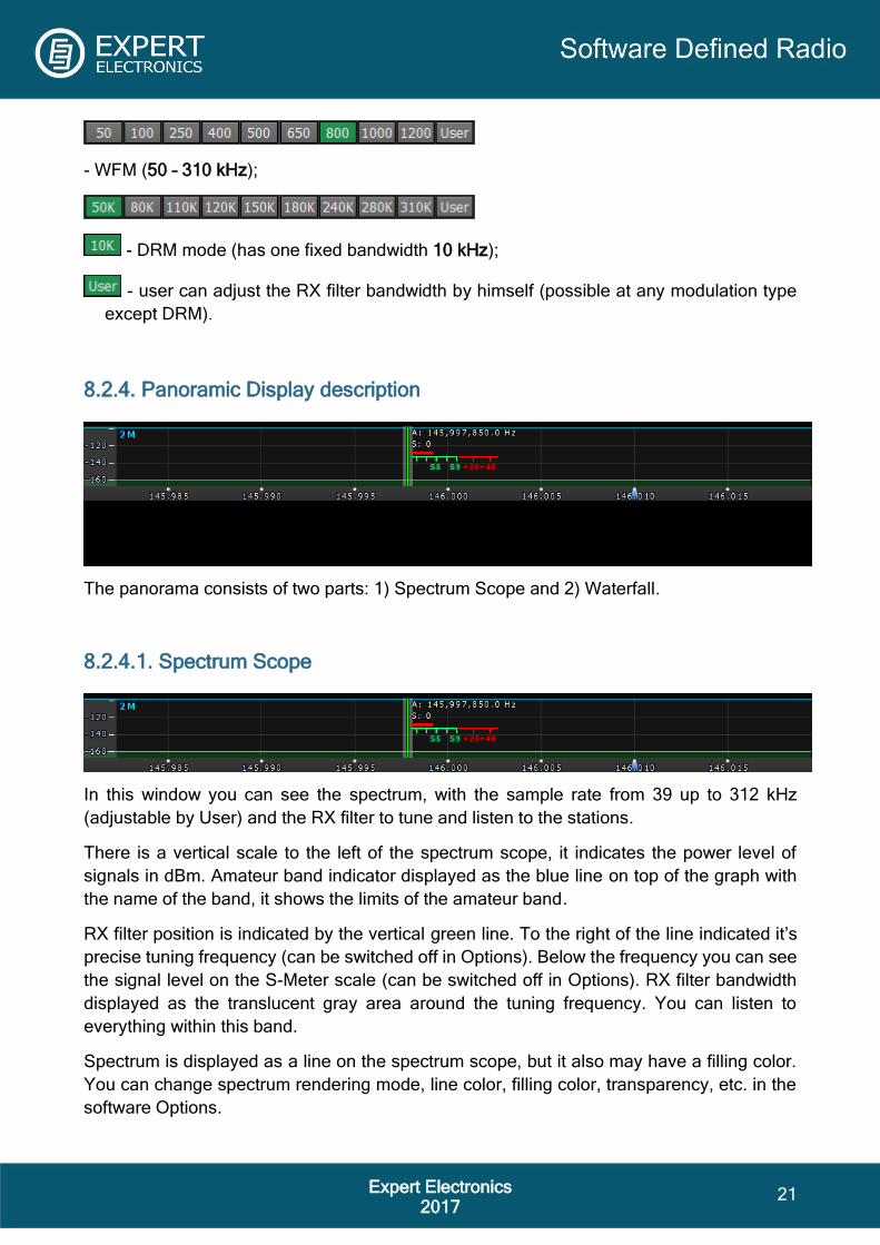
8.2.4. Panoramic Display description
The panorama consists of two parts: 1) Spectrum Scope and 2) Waterfall.
8.2.4.1. Spectrum Scope
In this window you can see the spectrum, with the sample rate from 39 up to 312 kHz
(adjustable by User) and the RX filter to tune and listen to the stations.
There is a vertical scale to the left of the spectrum scope, it indicates the power level of
signals in dBm. Amateur band indicator displayed as the blue line on top of the graph with
the name of the band, it shows the limits of the amateur band.
RX filter position is indicated by the vertical green line. To the right of the line indicated it’s
precise tuning frequency (can be switched off in Options). Below the frequency you can see
the signal level on the S-Meter scale (can be switched off in Options). RX filter bandwidth
displayed as the translucent gray area around the tuning frequency. You can listen to
everything within this band.
Spectrum is displayed as a line on the spectrum scope, but it also may have a filling color.
You can change spectrum rendering mode, line color, filling color, transparency, etc. in the
software Options.

22 Expert Electronics
2017
8.2.4.1.1. Spectrum Scope scaling
If you move the mouse cursor over the vertical scale a hand will appear. Press and hold the
right mouse button, then move it up/down to change the dBm scaling or press and hold the
left mouse button, then move it up/down to change the spectrum level.
Horizontal scale between the spectrum scope and waterfall shows the frequency of the
certain point on the spectrum. If you move the mouse cursor over the horizontal scale a hand
will appear. Press and hold the right mouse button, then move it left/right to zoom in/out the
panorama or press and hold the left mouse button, then move it up/down to change the ratio
of the spectrum to waterfall.
Zoom in/out of the panorama is carried out relative to the Zoom position marker.

23 Expert Electronics
2017
You can change the Zoom position in two ways:
1. Press and hold the left mouse button on the Zoom marker and drag it left/right,
2. Click the mouse wheel on frequency scale.
8.2.4.1.2. Frequency tuning
There are several ways of tuning on the spectrum scope:
Quick tuning by the mouse click.
On the spectrum scope mouse cursor looks like the crosshair. Alongside this cursor
displayed the exact frequency and dBm level in the certain point. The RX filter moves to this
position by the click of the left mouse button.
Dragging the RX filter over the spectrum scope.
Press and hold the left mouse button on the filter, then drag it left/right to the required
position.
Moving the spectrum, the RX filter is standstill.
Press and hold the right mouse button anywhere on the spectrum, then move the spectrum,
the filter will not change its position relatively to the spectrum.
Moving the spectrum, the RX filter moves along.
Press and hold the right mouse button anywhere on the filter and move it left/right. Basically,
this is not a way of tuning. It allows to observe the air outside the panorama window, not
changing the tuning frequency.
Fine tuning.
More accurate tuning can be performed by rotating the mouse wheel with accuracy specified
in the "Step" menu.

24 Expert Electronics
2017
Сlick on the digit of the frequency indicator.
Left button – increase value; right button – decrease value; wheel – all digits on the right
become zero.
Rotate mouse wheel on the digit of the frequency indicator.
Rotate forward – increase value; rotate backward – decrease value
Aside from the listed above ways of tuning, implemented the synchronous tuning between
the bandscope and the main receivers. Press the right mouse button on the required
frequency on the bandscope, the main receiver simultaneously tunes to this frequency.
Mouse wheel click on the digit of the frequency indicator.
Hover the mouse cursor on the required digit on the frequency indicator and click the mouse
wheel –lower digit will turn zero.
Synchronous tuning by the click on the bandscope.
Hover the mouse cursor on the required place on the bandscope and click left mouse button
– RX filter will move to the required location on both bandscope and panorama.
8.2.4.2. Waterfall
Waterfall graphic - timed spectrum scope in format: amplitude - brightness, frequency -
horizontal, time - vertical. The comfortable settings are set by default, but you can change
them if necessary.
There are three ways of the waterfall rendering: rainbow, monochrome and custom, you can
adjust them in the software Options.
8.3. Status bar
The status bar displays the following information (from left to right):
ExpertSDR2 window resolution / CPU load in percent / Connection status to ColibriNANO
(red – no connection; blue – connection).
Coordinated Universal Time (UTC).
Current date / Local Time.

25 Expert Electronics
2017
9. ExpertSDR2 software fine tuning
For fine tuning of the ExpertSDR2 software open the Options menu by pressing the Options
button in the top right corner of the software window.
Note!
- If you changed anything in the menu and you don't like it, but you forgot the default value,
you can reset ALL settings to default values by clicking the Global Default button. The same
applies to some enclosed menus, where you can find the Global Default button.
- You can check the changes without leaving the Options window, just click the Apply button.
- If you are satisfied with the changes and don't want to change anything else, click the OK
button to close Options window.
WARNING! We recommend you study this section of the manual very carefully, because a
lot of settings can be changed/selected from sub-menus.
9.1. Device menu
In the Device menu you can find software functions of the signal processing and hardware
settings.
9.1.1. Device settings
Left part of the Device menu shows hardware settings.
Device – device type menu. Shows that the
ExpertSDR2 works in the ColibriNANO mode.
ColibriNANO: - shows the connection status
between the receiver and PC. Even if the receiver
is plugged in, but required USB drivers are not
installed, the status would be disconnected.

26 Expert Electronics
2017
Sample Rate – IF sample rate, equals the panorama
bandwidth. You can select one of nine panorama
bandwidth values.
Preamp Auto – if enabled, this feature automatically adjusts
preamp/attenuator level based on the signal level on the
ADC input. The purpose of this feature is to maximize the
ADC usage, but do not overload the ADC (we recommend
keeping this feature ON).
9.1.2. VAC tab
If the ExpertSDR2 and digital modes software run on the same computer, they can be
connected via a Virtual Audio Cable (VAC) without wires and sound cards.
Enable – set the Enable checkbox to enable
Virtual Audio Cable.
Driver – select the audio cable's or sound
card driver type.
RX – select a sound card or virtual audio
cable for audio output.
Sample rate – sampling frequency.
Buffer size – size of the buffer.
Channels – select the amount of the sound card's or virtual audio cable used channels.
Latency – signal delay time.
RX gain – additional signal amplifying in the virtual audio cable's RX path in dB.
Note! Before enabling the VAC, make sure all settings for audio devices are correct.
9.1.3. DSP tab
On the DSP tab, you can see the AGC's and Digital Signals Processing settings. There are
two types of settings in the drop-down menu:
AGC – receiver’s AGC settings.
DSP – digital processing filter's settings.
Receiver’s AGC settings
There you can find fine AGC settings. AGC settings are divided by the processing speed on
Long, Slow, Med, Fast and User.

27 Expert Electronics
2017
Each settings type has its own tab and differs from others in terms of Attack, Decay and
Hang time.
AGC parameters:
Slope – set the slope of the transfer characteristic.
Attack – when a signal gets stronger, this value determines
how quickly the AGC will decrease gain.
Decay – when a signal gets weaker, this value determines how
quickly the AGC will increase gain.
Hang time – signal recovery time.
Threshold – AGC trigger threshold.
Default – reset AGC setting to the default level. Press the Default button if you set wrong
AGC values and don't like the result. Each AGC tab has a Default button.
Digital processing filter's settings.
There you can find fine the settings of the receiver's digital processing filters. DSP functions
clears the signal from abnormal noises and crosstalk. These are the standard functions:
NR – Noise Reduction, removes the white noise. This is a special adaptive filter, which
removes any abnormal noises from the air in the RX filter band.
ANF – Auto Notch filter, removes the carrier signals. This is a special adaptive filter, which
removes any periodical signals from the air in the RX filter band.
NR and ANF parameters:
Taps – filter taps, determines the quality of the filter functionality.
Delay – trigger delay time.
Rate – set the adaptation rate of the filter.
Leak – set the signal's level.

28 Expert Electronics
2017
APF - Analog peak filter for CW and SSB mode. Provides a more comfortable listening of
the CW signals by amplifying the CW signal in the center of the receive filter (triangle filter's
AFC (amplitude-frequency characteristic) in the filter bandpass).
CW APF – Analog Peak-Filter for CW mode:
Gain – Analog peak-filter amplifying factor.
Quality – Analog peak-filter quality (slope sharpness).
SSB APF – Analog Peak-Filter for SSB mode:
Gain – Analog peak-filter amplifying factor.
Quality – Analog peak-filter quality (slope sharpness).
Frequency – central frequency of the voice signal.
Filter taps - receiver's filter taps.
Set the required receiver's filter taps for each mode separately, by default it's 1537.
The higher the receiver's filter taps value, the more rectangular the filter's shape, but it also
increases the signal pass delay. That is why the user should find the best settings for himself,
between acceptable filter slopes steepness and signal delay. Optimal filter taps are set by
default.
Noise blanker – Noise Blanker, removes impulse interference.
Noise blanker parameters:
Threshold NB 1 – filter 1 trigger threshold. Set the required filter 1 trigger threshold,
depends on the interference level.
Threshold NB 2 – filter 2 trigger threshold. Set the required filter 2 trigger threshold,
depends on the interference level.
DSE - Digital Surround Effect for CW signals. Provides a space orientation in stereo phones,
stations from lower frequencies are louder in the left channel, stations from higher
frequencies are louder in the right channel. The signal in the filter's center is equally heard
in both channels of stereo phones.
Note! DSE effect cannot be heard in mono phones.
DSE – Digital Surround Effect for CW signals:
Quality – DSE filter quality. The higher the quality value the stronger the function's effect.

29 Expert Electronics
2017
Swap channels - swap right and left receiver's channels. Set the Swap channels checkbox
for correct DSE functionality, if required. Correct functionality - slowly increasing the
receiver tuning frequency, while receiving the CW signal, sounds as if CW signal moves
from the right to the left channel.
WFM – Wide FM standard:
USA – set this checkbox to listen to WFM stations in the USA or South Korea.
DIG offset – frequency offset, use when you operate in digital modes. Whether to use
frequency offset or not depends on the digital mode software. Look for tips in the instruction
for your digital mode software.
Default - press to return settings to the default state. Each settings category has the Default
button. Press the Default button if you set wrong values and don't like the result.
9.1.4. Expert tab
On the Expert tab, you can see the fine hardware settings of the receiver.
Note! All settings in this tab are stored in the receiver’s non-volatile EEPROM memory.
After setting the required values, press the Write button to store the settings in the memory.
To read the current settings state from the memory, press the Read button.
Auto-read happens with every software launch.
It allows you to seamlessly change PC’s and preserve the same hardware settings of the
receiver.
Preamp correction – correction menu created for operation with external preamps or
attenuators, for compensation. If you plan to use the receiver without external devices, you
don’t need this menu.
Frequency coefficient – correction menu of the receiver’s frequency tuning. Set the coefficient
that the receiver’s tuning frequency would be equal to the real frequency of the received
signal.
Note! Correction of the displayed frequency could be made according to the time signals on
the 4.996MHz, 9.996MHz or 14.996MHz (preferably) frequencies, where you can find easily

30 Expert Electronics
2017
tracked pulse signals. If they do not match with the tuned frequency, adjust the Frequency
coefficient till the frequency match.
The higher the frequency of the used time signal, the higher calibration accuracy.
Calibration should be performed with the maximum panorama zoom and maximum FFT size
of the panorama.
After you set the frequency correction coefficient, press the Write button.
The devices are calibrated at manufacturing; additional calibration is not required.
9.2. Sound card menu
In the Sound card menu, you can see the settings of the audio devices, which can be used
with the receiver.
9.2.1. Sound card
In the Sound card category, you can see the settings of the sound card, which can be used
for sound output in the RX mode.
Note! Signal output delay via the sound card can reach 30-500 ms. It can be adjusted with
buffer size (smaller values equal lower delay) or selecting different Audio driver (MME – the
biggest latency / WDMKS – moderate latency / ASIO – minimal latency).
Enable - checkbox to enable PC's
sound card. Set the Enable checkbox
to enable sound output via the sound
card.
Driver – select the sound card's driver
type.

31 Expert Electronics
2017
Output – select the sound card's physical output.
Channels – select the amount of active sound card's channels.
Sample rate – sampling frequency.
Buffer size – buffer size.
Latency – signal delay time.
Note! Before you'll enable the Sound card by the Enable checkbox, make sure that all sound
devices settings are set correctly.
9.2.2. Line output
In the Line output category, you can see the settings of the sound card or virtual audio
cables, which could be used for sound output.
Note! Sound output via the Line output will be simultaneous with the sound output from the
receiver.
Line output volume has a constant max value and cannot be changed by the operator.
As a rule, sound output via the Line output is used for recording communications on
contests and other purposes.
Enable - Checkbox to enable Line
output. Set the Enable checkbox to
enable Line output.
Driver – choose the sound device'
driver type.
Output – choose the sound device'
physical output.
Channels – choose the amount of active sound device' channels.
Sample rate – sampling frequency.
Buffer size – buffer size.
Latency – signal delay time.
Note! Before you'll enable the Line output by the Enable checkbox, make sure that all sound
devices settings are set correctly.
9.3. Display menu
In the Display menu you can see the settings of the receiver’s software display.
Display settings are placed according to their functionality:
Main window | Spectrum | Waterfall | Grid | Filter | Background | Indicators

32 Expert Electronics
2017
9.3.1. Main window tab
On the Main window tab, you can see the settings of the receiver’s software main window
display.
Title text - input box to enter the title. Enter in the Title text box - your call-sign or other
information, it will always be displayed in the software title.

33 Expert Electronics
2017
Language - interface language menu. Choose the required language from the list.
Skins - software color theme menu. Choose the required software color theme from the list.
Lock Screensaver - lock screensaver checkbox. Set the Lock Screensaver checkbox to
block the display turn off by the Windows OS. Recommended checkbox setting - on.
ExpertSDR2 stays on top - on top checkbox. Set the ExpertSDR2 stays on top checkbox to
see ExpertSDR2 window constantly on top of other windows. Recommended checkbox
setting - off.
Autostart device - receiver's autostart checkbox. Set the Autostart device checkbox to
automatically start the receiver after the launch of the software. Recommended checkbox
setting - on.
Show current profile in window title - display the current profile in the software window title.
Set the Show current profile in window title checkbox to display the current profile (if the
profile is on) in the software window title.
Display 4K – display mode for 4K monitors.
Amateur region - amateur region menu.
Choose the region you are currently in, in
the Amateur region menu. It affects the
position of the amateur bands in the software. Set region 1 for EU/Russia/Africa/Middle East,
region 2 for North and South Americas, region 3 for Asia/Oceania.
Use 60M band – set the Use 60M band checkbox to enable 60M band.
Note! After you selected the amateur region and/or set/unset the checkbox Use 60M band
you'll see the notification window, that the settings will be applied after the restart of the
software. Restart the software.
9.3.2. Spectrum tab
On the Spectrum tab you can see the receiver’s spectrum settings.

34 Expert Electronics
2017
FFT size - Fast Fourier Transform (FFT) size of the spectrum scope. Choose the required
FFT size. The higher FFT size, the higher spectrum scope resolution by frequency, along
with the higher processor load.
Averaging type - spectrum scope averaging type menu. Choose the averaging type from the
list: Linear, root-mean-square (Rms), Exponential, which suits you best.
Averaging num - number of samples for averaging. Set the required number of samples for
averaging. The bigger the number of samples, the slower the specter will change on the
graph.
Update period - spectrum scope update period. Set the required specter's graph update
period. The bigger the number, the more FPS on the spectrum scope, along with the higher
processor load.
Render mode - specter render mode: lines, gradient. Set the required specter render mode.
In Lines mode:
Line color - spectrum scope line color. Select the required line color from the palette.
Fill color - fill color of the spectrum scope lower area. Select the required fill color from the
palette.
Fill transparency - transparency slider for the spectrum scope lower area filling. Set the
required filling transparency level.
In Gradient mode:
Color top – top color of the spectrum.
Color bottom – bottom color of the spectrum.

35 Expert Electronics
2017
Show bands - set the Show bands checkbox to show amateur bands borders at the top of
the spectrum scope (blue line).
Save limits for each band - save spectrum scope amplitude limits for each band. Set the
Save limits for each band checkbox to enable the software to save set spectrum scope limits
for each band.
Save zoom for each band - save spectrum scope zoom settings for each band. Set the Save
zoom for each band checkbox to enable the software to save spectrum scope zoom settings
for each band.
Zoom center follows VFOA - zoom center marker locked on the VFOA position on the
spectrum scope. This function was added for the E-Coder control panel and Main Knob of
the MB1 transceiver i.e. while you tune frequency with valcoder, zoom marker follows VFOA.
Animation - spectrum scope animation while transition between bands. Set the Animation
checkbox to enable animation.
Show cursor info - show frequency and dB level of the cursor position. Set the Show cursor
info checkbox to enable info display near the cursor on the spectrum scope.
Show the difference between VFOA and VFOB - show the difference between VFOA and
VFOB. Set the Show the difference between VFOA and VFOB checkbox to display the
difference between VFOA and VFOB near the cursor.
Auto hide cursor - automatically hide the cursor from the spectrum scope. Set the Auto hide
cursor checkbox to let the cursor disappear after idle 2 seconds.
Show stations from Memory panel - show the stations previously stored in the frequency
memory. Set the Show stations from Memory panel checkbox to show on the spectrum
scope previously stored stations as markers (blue dots in the top area of the spectrum
scope). When rollover the station's marker you'll see the commentary.
Show spots - show spots from the CW Skimmer on the spectrum scope. Set the Show spots
checkbox to show spots from the CW Skimmer on the spectrum scope as markers with call-
signs.
Show broadcast HF bands - enable for display of broadcast HF bands on panorama and
Band Scope.

36 Expert Electronics
2017
9.3.3. Waterfall tab
On the Waterfall tab, you can see the receiver’s waterfall settings.
Level mode - waterfall bright menu.
Choose the bright mode from the
list: Automatic, Synchronous:
Automatic mode depends on
air signals and set offset in the
settings below.
Synchronous mode depends
on the set limits of the spectrum
amplitude.
Offset top - offset input box by the
top dB level relatively to signals level. Set the offset in the Offset top box to determine the
maximum brightness relatively to the max signals' levels.
Offset bottom - offset input box by the bottom dB level relatively to signals level. Set the
offset in the Offset bottom box to determine the minimum brightness relatively to the min
signals' levels.
Render mode - waterfall render mode menu: Rainbow, Monochrome, Custom. Choose the
required color render of the waterfall, depending on your choice or tasks. In the Custom
mode you have three color presets: 1,2,3 and User adjustable mode.
In the User preset there are 6 color markers at maximum. Double click of the left mouse
button on the color marker opens the color menu, double click of the right mouse button on
the color marker delete it. Double click of the left mouse button on the empty space adds the
color marker.
Remove flicker - checkbox to remove the waterfall flickers. Set the Remove flicker checkbox
to get rid of the texture flickers in the waterfall. Also it slightly clears the waterfall from air
noises.
Rate - waterfall movement speed slider. Set the Rate slider according to the required
waterfall movement speed.

37 Expert Electronics
2017
9.3.4. Grid tab
On the Grid tab you can see the spectrum scope grid display settings.
Color - color of the spectrum scope grid. Choose the
required grid color from the palette.
Transparency - grid transparency slider. Set the required
grid transparency by moving the slider.
9.3.5. Filter tab
In this tab, the color of filters and the necessity to display the additional text information are
selected.
Show filter on waterfall - show receiver(s) filter on the waterfall. Set the Show filter on
waterfall checkbox to show receiver(s) filter on the waterfall.
Show filter text – show text info near the receiver's filter on the spectrum. Set the Show filter
text checkbox to display filter's tuned frequency, signal level in S-units etc. in the used filter
bandwidth.
Show S-Meter – enable animated S-Meter near the receivers' filter on the spectrum. Set the
Show S-Meter checkbox to display S-Meter near the receiver's filter. In the RX Filter A, RX
Filter B, TX Filter categories displayed filters' color and transparency settings.
Filter color - filter's frequency color menu. Choose the required filter's tuned frequency color
from the palette.
Band filter color - filter's bandwidth color menu. Choose the required filter's bandwidth color
from the palette.

38 Expert Electronics
2017
Transparency - filter's transparency slider. Set the required filter's transparency.
In the Rit/Xit category displayed RIT active zone settings.
Rit/Xit zone color - RIT active zone color menu. Choose the required RIT active zone color
from the palette.
Transparency - RIT zone transparency slider. Set the required RIT zone transparency.
9.3.6. Background tab
On the Background tab, you can see the spectrum scope background settings.
Background type - spectrum scope background type menu: Solid, Gradient, Image. Choose
in the Background type menu spectrum scope background render type.
In the Solid mode, available settings are:
Color – background color menu. Choose the
required background color from the palette.
In the Gradient menu, available settings are:
Color top – top gradient color of the
background. Choose the required top
gradient color from the palette.
Color bottom – bottom gradient color of the
background. Choose the required bottom
gradient color from the palette.

39 Expert Electronics
2017
In the Image menu, available settings are:
Image menu – image
presets menu (Forrest,
Bubbles, Space, Water,
User). Pick the required
image from the menu or
lock one of your own
images.
Brightness – background
image brightness slider.
Set the required background image brightness.
User image - choose the required image to be displayed on the background. Press the Open
button, in the opened window choose the image file to set as the background.
Note! If the image file wasn't chosen previously via the Open button, then if you choose the
User image in the presets list it'll open the window to choose the image file.
Supported files types: png, jpg, jpeg, bmp.
9.4. САТ menu
In the CAT menu, you can see the CAT-system settings. CAT-system is the receiver’s
exchange interface with an external devices and software.
CAT-interface is used to control the receiver from a third-party software. This could be
contest logs, digital modes decoder-software, SAT-tracker etc.
There are two ways to use the ColibriNANO with an external transceiver: 1) ExpertSDR2 software has the ECATv1
protocol, use it to synchronize the ColibriNANO
and your transceiver via RigSync software
http://www.qrv.com/rigsync.html
ECATv1 - exchange protocol compatible with
TS-480 transceiver. This protocol allows to
exchange data with an external devices and
software via COM-port.
RX1 tab contains CAT-system settings via COM-
ports.
Enable CAT – checkbox to enable control of the
receiver via the CAT-system.
Port name – COM-port number.
Parity – parity.

40 Expert Electronics
2017
Data – amount of data in bits.
Stop bit – amount of stop bits.
Baud rate – port speed.
Enable SubRX control (FR command) - checkbox to enable control of the sub-receiver via
the CAT-system. Set the Enable SubRX control (FR command) checkbox to enable the
control of the SubRX via the CAT-system.
Antenna switch control – checkbox to enable control of the antenna switch via the CAT-
system. Set the Antenna switch control checkbox to enable the control of the antenna switch
via the CAT-system. Useful for the Ham Radio Deluxe software.
Global volume control – when this checkbox is enabled, you control the global volume with
the Volume slider, on the top of the software window, from the CAT-system.
Recommended when you use one RX or VFO A only, SubRX is disabled.
View log – display CAT command log.
2) There is an experimental function to synchronize ColibriNANO
with an external transceiver via the OmniRig software
http://www.dxatlas.com/omnirig/.
OmniRig - exchange protocol via the OmniRig software.
Using the OmniRig software you can send a limited set of control
commands.
Available control commands:
– Set VFO frequency, if no VFOB in the CAT protocol;
– Set VFO A frequency;
– Set VFO B frequency;
– Enable receiver's RIT offset;
– Set RIT offset; – Reset RIT offset;
– Enable transceiver's XIT offset;
– Set mode type;
– Enable SPLIT.
In the OmniRig menu you can find the settings of the OmniRig software.
Enable - set the Enable checkbox to control the receiver via the OmniRig software.
Settings - press the Settings button to open the OmniRig software settings.
Note! If the ExpertSDR2 software uses OmniRig protocol to exchange data with an external
contest log software, which also uses OmniRig, then COM-port and other settings in the
OmniRig software are not required. Select in the OmniRig settings any idle COM-port in the
system, to avoid conflict.

41 Expert Electronics
2017
OmniRig RX1 Status - RX1 receiver and OmniRig connection
status.
OmniRig RX2 Status - RX2 receiver and OmniRig connection
status.
9.5. Panel menu
In the Panel menu, you can see the settings of the E-Coder control panel.
In the drop-down Device menu, you can select the type of the connected control panel. In
the meantime, only one type is available - E-Coder.
Note! If one E-Coder panel is connected to the receiver, in the Panel menu displayed one E-
Coder 1 tab, if several E-Coder panels are connected to the receiver, in the Panel menu
displayed a several tabs E-Coder 1, E-Coder 2 etc. with identical settings for each panel.
In the left part of the menu you can see the schematic picture of the E-Coder panel with
buttons and knobs. Press any button, you'll see the list of the available functions.
Note! The list of the available functions is constantly growing. Keep track of the software
updates.
You can make a request to add a new function on the control button.

42 Expert Electronics
2017
The following functions may be assigned on the E-Coder panel buttons:
Unused – button is unused.
Main:
AGC Up/Down – AGC type switching.
Band Up/Down – band switching.
Filter Up/Down – receiver's filter switching.
Mode Up/Down – mode switching.
PA – enable/disable power amplifier.
Preamp Up/Down – preamp or attenuator level switching.
Power ON/OFF – transceiver's power on/off.
RX ANT - enable/disable receive antenna.
Step Up/Down – change the tuning step.
WF - enable/disable Wide Filter. Filter for all Nyquist zone. If in the Device menu settings,
you set Auto enable checkbox, then you don't need this function on the panel.
Zoom In/Out – spectrum zoom modes switching.
VFO/RX2:
A>B - assign the frequency from heterodyne VFO A to heterodyne VFO B.
B>A - assign the frequency from heterodyne VFO B to heterodyne VFO A.
B<>A - frequency exchange between VFO A and VFO B.
Change VFO A/VFO B – switching between VFO A and VFO B.
IF as RIT – tune the RIT offset by moving the filter over the panorama.
LOCK - lock the frequency tuning.
RX2 On/Off - enable/disable RX2.
RIT On/Off – enable/disable RIT offset.
RIT Reset – reset RIT offset to 0.
Sub RX On/Off - enable/disable SubRX.
Switch DDS/IF – tuning the frequency by moving the filter over the panorama, in other words
changing the digital IF, or when filter stands still and spectrum moves, this is the central
frequency tuning.
Switch Receiver – switching between software RX1 and RX2. Main knob will tune the
frequency of one of the receivers

43 Expert Electronics
2017
While you operate both RX1 and RX2, usually you need to listen to either only one of them
or both of them, but in different channels (left / right). To do that we added special functions
to the E-Coder panel, which set the mixer for both RXs.
Audio:
Listen both RX1, RX2 – default settings, both RXs have equal volume in both channels.
Listen RX1 only – listen to the RX1 in both channels.
Listen RX2 only - listen to the RX2 in both channels.
Listen RX1 in left channel, RX2 in right – listen to the RX1 in the left channel and RX2 in the
right channel.
Listen RX1 in right channel, RX2 in left - listen to the RX1 in the right channel and RX2 in
the left channel.
Similar settings were added for VFOs:
Listen both VFO A/B - default settings, both VFOs have equal volume in both channels.
Listen VFO A only - listen to the VFO A in both channels.
Listen VFO B only - listen to the VFO B in both channels.
Listen VFO A in left channel, VFO B in right - listen to the VFO A in the left channel and VFO
B in the right channel.
Listen VFO A in right channel, VFO B in left - listen to the VFO A in the right channel and
VFO B in the left channel.
Mute – switch off sound.
Switch RX and mute former – change the software receiver and mute former one.
Voice recording – enable/disable voice recording.
Volume Up/Down – volume adjustment.
DSP:
ANF – enable/disable auto notch filter.
APF - enable/disable analog pick filter.
BIN – enable/disable binaural mode.
NR – enable/disable noise reduction.
NB1 – enable/disable noise blanker 1.
NB2 – enable/disable noise blanker 2.

44 Expert Electronics
2017
SQL – enable/disable squelch.
The following functions may be assigned on the E-Coder panel knobs:
Unused – encoder is unused.
Volume – volume adjustment.
SQL – squelch threshold adjustment.
Filter Low/High – tuning the frequency of the low/high filter's front.
Filter Width – adjusting the filter width.
Filter Shift - shifting the filter's central frequency.
IF – tuning the frequency by moving the filter over the panorama.
RF Gain – RF Gain control.
RIT Offset – adjusting the RIT Offset.
In the right part of the menu you can see the main panel settings:
Enable - enable E-Coder panel control.
Use IF - frequency tuning by moving the filter over the panorama.
Use IF as RIT - tuning by IF when the RIT offset is on.
VFO B - enable sub-receiver.
Key Led - enable backlit keypad.
Encoder Led - enable backlit encoder.
Transfer PTT to TCI – enable reroute of the PTT signal from the panel to TCI, has higher
priority than COM-port PTT transfer (described below).
RX1/RX2 menu - switching between RX1 and RX2 receivers, or assign exact E-Coder panel
to your receiver.
Volume - set the volume change step per knob's clack.
SQL - set the squelch threshold change step per knob's clack.
Filter High - set the filter's high limit change step per knob's clack.
Filter Low - set the filter's low limit change step per knob's clack.
Filter Width - set the filter's width change step per knob's clack.

45 Expert Electronics
2017
Filter Shift - set the filter's shift change step per knob's clack.
RF Gain - set the RF gain step per knob's clack.
Additional functions:
Enable PTT Transfer - rerouting of the PTT signal from the panel to the COM-port. Set the
Enable PTT Transfer checkbox to enable rerouting the PTT signal.
Port name - COM-port number.
DTR/RTS - select the COM-port line, which is used for transferring the PTT commands. Set
one of the DTR/RTS line checkboxes to set it as the control line.
There are three LEDs on the E-Coder panel, from left to right:
1) Lights green when the VFO B is active
2) Lights red when on TX
3) Lights orange when the RX2 is active
9.6. Features menu
In the Features menu, you can see the settings to launch other programs along with the
ExpertSDR2 software. This feature allows you to automatically launch required programs by
launching the ExpertSDR2 software.
Enable checkbox - enable program autorun in the list. Set the Enable checkbox in front of

46 Expert Electronics
2017
the corresponding program in the list.
Program 1-10 - program's button. Press the Prog X button to open the window and select
.exe file of the required program.
Delete button - program delete button. Press the Delete button if you need to delete a
program from the autorun list.
Arguments - input box to enter the argument after program's launch. Enter some text
message in the arguments input box for the corresponding program.
Note! Arguments allow to the same program to be launched with the different settings files
etc.
Read the instruction for the certain software you are going to use, in terms of which
arguments are supported.
9.7. ExpertSync menu
In the ExpertSync menu, you can see the settings of the network synchronization between
the receiver and other Expert Electronics devices.
This interface allows you to
synchronize the tuning frequency
and mode type between several
Expert Electronics devices via the
ExpertSync software (you may
download it from here).
Server address - input box for the
ExpertSync server IP address.
Enter the ExpertSync server IP
address. If the ExpertSync server is launched on the receiver’s PC, then the address will be
127.0.0.1.
Port - input box of the data exchange port. Enter the exchange port number in the Port input
box.
Connect - button to launch the connection between the receiver’s software and ExpertSync.
Press the Connect button to launch the connection between the receiver’s software and
ExpertSync. Blue indicator means there is a connection.
Sync RX1 - RX1 receiver sync button. Set the Sync RX1 checkbox to synchronize RX1
receiver with remote RX1 receiver.
Sync filter – set the Sync filter checkbox to synchronize the filter bandwidth with the other
device connected via the ExpertSync software.
Sync RIT - set the Sync RIT checkbox to synchronize the receive frequency offset (RIT) with
the other device connected via the ExpertSync software.

47 Expert Electronics
2017
9.8. CW Skimmer menu
In the CW Skimmer menu, you can see the connection settings between the receiver
software and CW Skimmer software or Internet spotter-server.
Settings in the CW Skimmer menu has two identical tabs RX1 with connection settings for
each software receiver, let's look at one of them.
Connect - button to launch the connection with the CW Skimmer software or Internet spotter-
server. Press the Connect button, after adjusting all settings, to make a connection with the
CW Skimmer software or Internet server-spotter.
Address - IP address or DNS name of the CW Skimmer/server. Enter this 127.0.0.1 address
or localhost, if you want to connect to the CW Skimmer, which is installed on the receiver’s
PC.
Port - input box of the data exchange port. Enter the exchange port number in the Port input
box.
Callsign - callsign input box. Enter your callsign if the server requires it.
Password - password input box. Enter the password if the server requires it.
To transfer the IQ signal in the CW Skimmer you need to adjust the settings of the audio
device in the RX IQ output category, it consists of:
Enable checkbox - enable the IQ signal transfer from the EpertSDR2 to the CW Skimmer.
Driver – audio device driver type.
Output – audio device physical output.
Channels – amount of the used channels of the audio device.

48 Expert Electronics
2017
Sample rate – sampling frequency.
Buffer size – buffer size.
Latency – signal delay time.
Note! If CW Skimmer is installed on the receiver’s PC, then for the signal output you need to
use Virtual Audio Cable.
Sync frequency - set the Sync frequency to synchronize the CW Skimmer frequency with
ExpertSDR2 frequency.
Tune frequency from CW Skimmer - CW Skimmer set the ExpertSDR2 frequency. Set Tune
frequency from CW Skimmer to tune the ExpertSDR2 frequency by the mouse click on the
station in the CW Skimmer.
More information of the ExpertSDR2 and CW Skimmer connection described in the guide
over the following link: ExpertSDR2_CW_Skimmer.pdf.
9.9. Shortcuts menu
In the Shortcuts menu, you can see the shortcut key combinations. With the help of the key
combinations you can control the receiver from your keyboard.
Note! Shortcuts will be active only if the receiver’s software window is in focus.
Enable - Shortcuts enable button. Set the
Enable checkbox to activate assigned
shortcuts.
Command – receiver’s functions column.
In the Command column displayed all
receiver’s functions available for
shortcuts.
Shortcut - column with the main shortcuts.
In the Shortcut column, you can set the
main receiver’s functions.
Shortcut RX1 - RX1 receiver shortcuts column. In the Shortcut RX1 column you can set RX1
receiver functions.
- shortcut button. Press the Shortcut button, then press the key combination on
the keyboard.
To delete a shortcut, press the Del button on the keyboard.

49 Expert Electronics
2017
9.10. IQ Recorder menu
In the IQ Recorder menu, you can select a folder where you will store IQ recordings.
This is the first step on a way to a complete IQ Player.
9.11. TCI menu
In the TCI menu, you can select a port for TCI connection of ExpertSDR2 with a third-party
software, with TCI support, and set the Enable checkbox.
TCI - Transceiver Control Interface was developed by Expert Electronics company, for
simple and still advanced connection between the ExpertSDR2 and third-party software. TCI
has all required control commands similar to CAT system, but even more, it can transfer IQ-
streams from the ExpertSDR2 to clients (third-party software such as signal Skimmers, etc)
via local network and the Internet, CW macroses and Audio In/Out streams for digital modes
(will be added soon). TCI is the universal multi-client interface (you can connect it to Loggers,
Skimmers, PAs, Antenna switches etc. at the same time).
https://github.com/maksimus1210/TCI - link to the list of files with the description of the
interface in English and Russian and source code of the demo-client software with TCI
support.

50 Expert Electronics
2017
9.12. Spot settings menu
In the Spot settings menu, you can adjust spot settings you receive from CW Skimmer and
telnet clusters.
In the Spot settings section (left part of the menu) you can set up Lifetime and Default color
for spots received from CW Skimmer.
In the right half of the menu you can add connections to telnet clusters to receive spots. To
add a cluster, enter a server address (you may find examples on this website
http://www.dxcluster.info/telnet/index.php), enter your callsign and select a certain color,
press the Add button, it’s done.
To delete a server connection, select it and press the Delete button on your keyboard.

51 Expert Electronics
2017
© Copyright 2017, Expert Electronics LLC. All Rights Reserved.
DUC DDC SDR Series, ColibriNANO receiver. Specifications are subject to change without
notice or obligation and specifications are only guaranteed within the amateur radio bands.
V1.1 - 11/21/2017