coil and magnet design for nuclear magnetic resonance in inhomogeneous field
TRANSCRIPT
IEEE TRANSACTIONS ON MAGNETICS, VOL. 42, NO. 12, DECEMBER 2006 3861
Coil and Magnet Design for Nuclear MagneticResonance in Inhomogeneous Field
Gaël Le Bec1;2, Jean-Paul Yonnet2, and Kosai Raoof1
Laboratoire des Images et des Signaux (UMR 5083 CNRS), ENSIEG, BP 46, 38402 St Martin d’hères Cedex, FranceLaboratoire d’Electrotechnique de Grenoble (UMR 5529 CNRS), ENSIEG, BP 46, 38402 St Martin d’hères Cedex, France
High-resolution nuclear magnetic resonance (NMR) spectrometry is possible in nonhomogeneous magnetic fields—such as those inportable equipment—if the static and the radio-frequency (RF) magnetic fields are perpendicular and correlated in the measurementvolume. From the easy-axis rotation theorem and the Amperian currents model, it is possible to exactly match two magnetic fields intwo-dimensional systems. We derive a basic probe element that fulfills these conditions. Then we present a portable NMR probe design.The static and RF magnetic fields of the probe are matched on a large volume.
Index Terms—Correlated magnetic fields, magnets, perpendicular magnetic fields, portable NMR, RF coils.
I. INTRODUCTION
THE nuclear magnetic resonance (NMR) systems operatethanks to the permanent magnetic field created by magnets
or superconductors, coupled with radio-frequency (RF) coils.Permanent-magnet sources are used for the static magnetic field.It creates a static magnetic field in all the measuring volume.Some nuclei (e.g., hydrogen) have a magnetic moment: this mo-ment precesses (rotates) around the direction of the static mag-netic field at the Larmor frequency where
is the gyromagnetic ratio. For hydrogen, the gyromagneticratio is rad s T . The spin precession is shownin Fig. 1.
The phase of the magnetic moments is arbitrarily distributedand there is an excess of magnetic moments in the direction of
. The result is a macroscopic magnetization parallel to thestatic magnetic field.
In order to obtain a NMR signal, a RF magnetic field isapplied in a direction perpendicular to the static magnetic field.So, the magnetization is flipped by an angle with respect tothe static field direction, as shown in Fig. 2.
After a relaxation time, the spin system returns to its equi-librium. A spectral analysis of the relaxation signal providesimportant information on the material. The signal-to-noiseratio (SNR) of the NMR experiment varies with the static fieldstrength: for this reason superconductors are widely used asmagnetic field sources.
Fig. 3 shows a conventional high-resolution NMR system: thehomogeneous static field is created by a large magnet andthe RF field is created by a coil. In such systems, the homo-geneity of the static magnetic field is in the order of magnitudeof 10 and a shimming system vanishes the field gradientsin the measurement volume [1], [2].
In inhomogeneous magnetic fields, the Larmor frequenciesof the magnetic moments are distributed on a large frequencyband. Hence, the synchronization of the magnetic moments islost and the macroscopic magnetization vanishes.
Digital Object Identifier 10.1109/TMAG.2006.884385
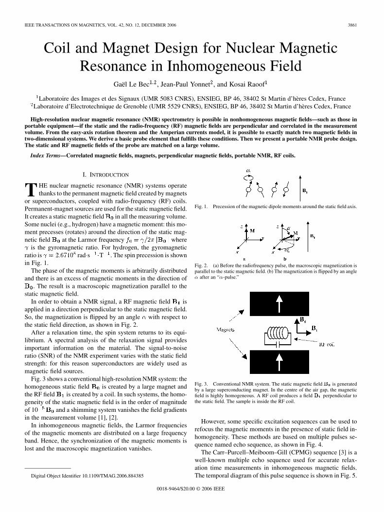
Fig. 1. Precession of the magnetic dipole moments around the static field axis.
Fig. 2. (a) Before the radiofrequency pulse, the macroscopic magnetization isparallel to the static magnetic field. (b) The magnetization is flipped by an angle� after an “�-pulse.”
Fig. 3. Conventional NMR system. The static magnetic fieldB is generatedby a large superconducting magnet. In the centre of the air gap, the magneticfield is highly homogeneous. A RF coil produces a field B perpendicular tothe static field. The sample is inside the RF coil.
However, some specific excitation sequences can be used torefocus the magnetic moments in the presence of static field in-homogeneity. These methods are based on multiple pulses se-quence named echo sequence, as shown in Fig. 4.
The Carr–Purcell–Meiboom–Gill (CPMG) sequence [3] is awell-known multiple echo sequence used for accurate relax-ation time measurements in inhomogeneous magnetic fields.The temporal diagram of this pulse sequence is shown in Fig. 5.
0018-9464/$20.00 © 2006 IEEE

3862 IEEE TRANSACTIONS ON MAGNETICS, VOL. 42, NO. 12, DECEMBER 2006
Fig. 4. Spin echo method in inhomogeneous magnetic field. (a;b) An initial�=2 pulse flips the magnetization in the x�y plane. The rotating magnetizationproduces the NMR signal detected by the RF coil. (c) Field inhomogeneitiesgenerate a dispersion of the magnetic dipole moments, hence there is a loss ofthe NMR signal. (d; e) A � pulse flips the magnetic moments. The phase of thespin is inverted. (f) The magnetic moments rephase and create a “spin echo.”(g) Temporal diagram of a spin echo sequence.
In situ NMR is a technique developed in the last two decadesfor petroleum applications. In 1980, Cooper and Jackson [4]proposed the first “inside-out” NMR apparatus for boreholemeasurements: an almost homogeneous static magnetic field isproduced outside the probe by opposite magnets. Informationon oil and rock pores is extracted from NMR relaxation dataobtained with the CPMG sequence.
A portable NMR surface scanner (the NMR-MOUSE, [5])was developed by Eidmann et al. in 1996. The principle of theNMR-MOUSE is shown in Fig. 6: a solenoidal coil in the gapbetween two magnets generates a RF magnetic field almostorthogonal to the static magnetic field . A thin slice of thesample is excited by the radiofrequency magnetic field. Thisportable NMR probe weighs about 2.5 kg and was built witha NdFeB magnet. The excitation frequency is 17 MHz and theRF power is about 200 W.
This apparatus can probe any proton-containing material,such as polymers and biomedical materials.
In spin systems, the electrons of the neighboring atoms lo-cally modify the effective static magnetic field applied on nu-clei. The result is a Larmor frequency shift named “chemicalshift” that yields information on the molecular structure.
Chemical shifts are refocused by multiple echo sequences,hence most of the portable NMR devices cannot be used forhigh resolution NMR spectroscopy. However, recent advancesin NMR sequence design [6], [7] have shown that high resolu-
Fig. 5. CPMG sequence for relaxation time measurements. Multiple � pulsesare applied to refocus the NMR signal. The amplitude of the echo signal decayswith the material relaxation time.
Fig. 6. Principle of the inside-out NMR probe designed by Eidmann et al.described in [5]. The static magnetic field B generated by two oppositemagnets and the RF field B are almost perpendicular. The sample is onthe coil surface. This NMR system is useful to measure relaxation times ofarbitrary large samples.
tion NMR spectroscopy is possible in inhomogeneous magneticfields if
in all the measurement volume.From this, we derive some criteria for inside-out NMR de-
sign. An ideal portable NMR probe should have the followingcharacteristics.
• Measurement volume and probe volume in the same orderof magnitude. The probe must be compact.
• Approximately homogeneous static magnetic field in agiven volume.
• Perpendicular and correlated RF and static fields.• High coil sensitivity and low coil resistance, for high SNR
and low power dissipation.In this paper, we propose a new concept to match the static
and the RF magnetic field in a large volume. This solution basedon the Amperian currents model and on the easy-axis rotationtheorem [8], [9] is for two-dimensional (2-D) systems. End ef-fects are discussed for realistic three-dimensional (3-D) probes.
II. THEORY
A. Amperian Currents and Magnetic Charges
In a uniformly magnetized material, the magnetic field can becalculated by an Amperian approach using equivalent surfacecurrent in vacuum:
(1)

LE BEC et al.: COIL AND MAGNET DESIGN FOR NMR IN INHOMOGENEOUS FIELD 3863
where is the magnetization and is a unit vector normal to themagnet surface. Furthermore, a Coulombian approach is pos-sible using equivalent magnetic charges
(2)
Using Coulombian calculations, the magnetic field created bya long bar-shaped magnet (Fig. 7) with a cross section ofand magnetized in the direction is [10]
(3)where is the magnetization. Equation (3) is available only for2-D problems. For 3-D problems, a solution is given in [10].
B. Magnetization Rotation
From (3), we can easily verify that a rotation of the mag-netization in the same magnet induced a rotation of themagnetic field (Fig. 8). This follows the easy-axis rotation the-orem used in magnetic bearing design [8] and synchrotron un-dulator design [9].
C. End Effects in 3-D Problems
In this section, we give a more general demonstration of theaxis rotation theorem and we derive conclusions on end effects.Let us consider the linear distribution of dipoles shown in Fig. 9.If is the magnetization, the linear density of dipoles becomes
and the magnetic field at point is given by
(4)
In a finite linear repartition, or. If a Taylor development gives
(5)
After a rotation of the linear repartition of dipoles by an angle, the magnetic field becomes
(6)
Fig. 7. Long bar-shaped magnet.
Fig. 8. Effect of a �=2 rotation of the magnetization in two dimensions: themagnetic field direction rotates by��=2 and its amplitude remains constant.
Fig. 9. Linear distribution of magnetic dipoles in bar-shaped magnets withmagnetization J and cross section S . For infinite distribution (' = ' =�=2) a rotation of all the dipoles induces a rotation � of the magneticinduction.
where is a 2 2 rotation matrix of an angle . The ex-ternal magnetic field of bar-shaped magnets with cross sec-tions and magnetization is
(7)
where . After a rotation by an angle ofeach magnetic dipole the magnetic field becomes
(8)
Then, the modulus of the overall induction at point isnot changed but the direction of the induction rotates. From (4),this result is true only if .
3864 IEEE TRANSACTIONS ON MAGNETICS, VOL. 42, NO. 12, DECEMBER 2006
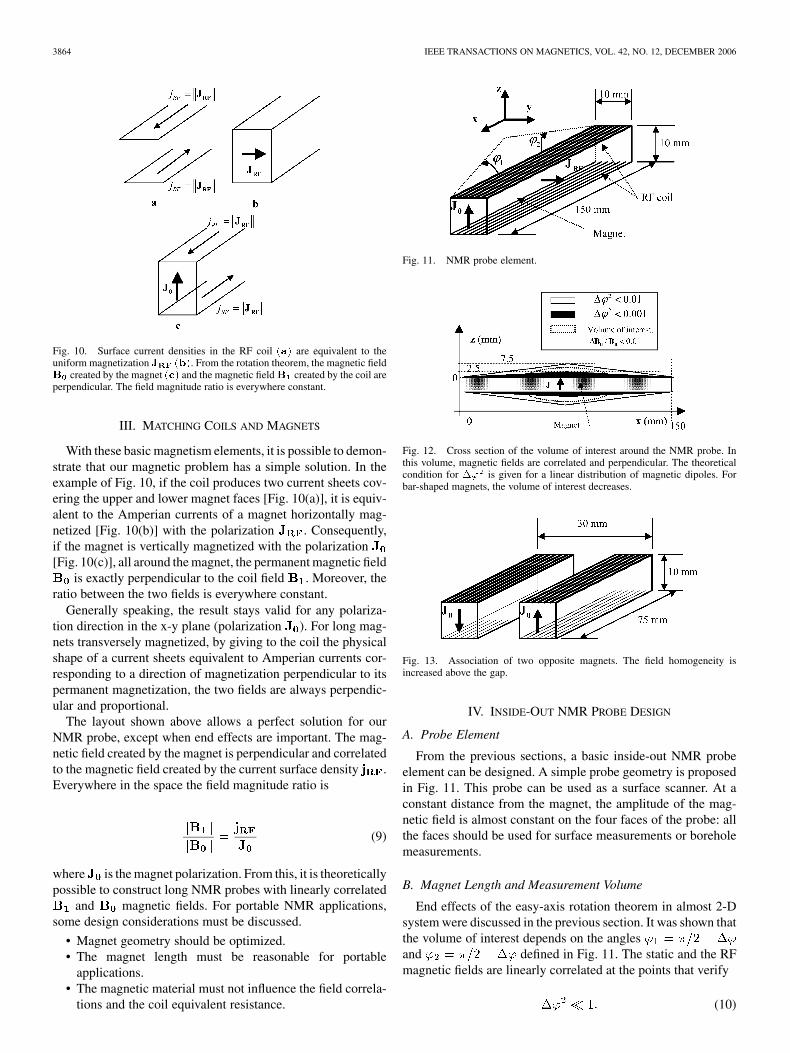
Fig. 10. Surface current densities in the RF coil (a) are equivalent to theuniform magnetization J (b). From the rotation theorem, the magnetic fieldB created by the magnet (c) and the magnetic fieldB created by the coil areperpendicular. The field magnitude ratio is everywhere constant.
III. MATCHING COILS AND MAGNETS
With these basic magnetism elements, it is possible to demon-strate that our magnetic problem has a simple solution. In theexample of Fig. 10, if the coil produces two current sheets cov-ering the upper and lower magnet faces [Fig. 10(a)], it is equiv-alent to the Amperian currents of a magnet horizontally mag-netized [Fig. 10(b)] with the polarization . Consequently,if the magnet is vertically magnetized with the polarization[Fig. 10(c)], all around the magnet, the permanent magnetic field
is exactly perpendicular to the coil field . Moreover, theratio between the two fields is everywhere constant.
Generally speaking, the result stays valid for any polariza-tion direction in the x-y plane (polarization ). For long mag-nets transversely magnetized, by giving to the coil the physicalshape of a current sheets equivalent to Amperian currents cor-responding to a direction of magnetization perpendicular to itspermanent magnetization, the two fields are always perpendic-ular and proportional.
The layout shown above allows a perfect solution for ourNMR probe, except when end effects are important. The mag-netic field created by the magnet is perpendicular and correlatedto the magnetic field created by the current surface density .Everywhere in the space the field magnitude ratio is
(9)
where is the magnet polarization. From this, it is theoreticallypossible to construct long NMR probes with linearly correlated
and magnetic fields. For portable NMR applications,some design considerations must be discussed.
• Magnet geometry should be optimized.• The magnet length must be reasonable for portable
applications.• The magnetic material must not influence the field correla-
tions and the coil equivalent resistance.
Fig. 11. NMR probe element.
Fig. 12. Cross section of the volume of interest around the NMR probe. Inthis volume, magnetic fields are correlated and perpendicular. The theoreticalcondition for �' is given for a linear distribution of magnetic dipoles. Forbar-shaped magnets, the volume of interest decreases.
Fig. 13. Association of two opposite magnets. The field homogeneity isincreased above the gap.
IV. INSIDE-OUT NMR PROBE DESIGN
A. Probe Element
From the previous sections, a basic inside-out NMR probeelement can be designed. A simple probe geometry is proposedin Fig. 11. This probe can be used as a surface scanner. At aconstant distance from the magnet, the amplitude of the mag-netic field is almost constant on the four faces of the probe: allthe faces should be used for surface measurements or boreholemeasurements.
B. Magnet Length and Measurement Volume
End effects of the easy-axis rotation theorem in almost 2-Dsystem were discussed in the previous section. It was shown thatthe volume of interest depends on the anglesand defined in Fig. 11. The static and the RFmagnetic fields are linearly correlated at the points that verify
(10)

LE BEC et al.: COIL AND MAGNET DESIGN FOR NMR IN INHOMOGENEOUS FIELD 3865
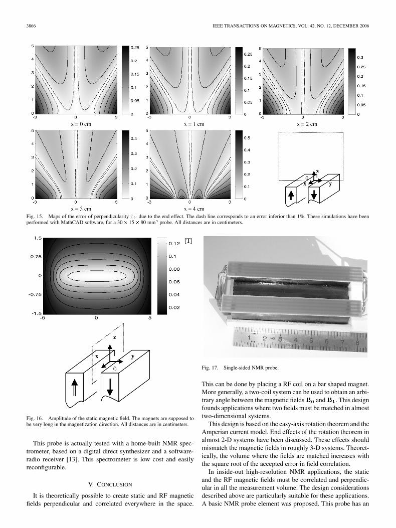
Fig. 14. Maps of the error of correlation " due to the end effect. The dash line corresponds to an error inferior than 1%. These simulations have been performedwith MathCAD software, for a 30� 15� 80 mm probe. All distances are in centimeters.
In practice, the acceptable value for depends on the mag-netic field gradients [11]. A cross section of the volume of in-terest is shown in Fig. 12 for different values of .
C. Association of NMR Probe Elements
Several basic probe elements should be associated to increasethe magnetic field homogeneity. Moreover, end effects shouldbe limited by a multiple element design. Using two magnets(Fig. 13) seems to be a good compromise between field homo-geneity, end effects, and system complexity.
D. Magnetic Field Simulations
The geometry of our system is simple and analytical modelsmay be used for numerical simulations. The permanent magnetsand the RF coils have been described by equivalent magneticcharges: the and magnetic fields were calculated using aCoulombian approach. The correlation and the perpendicularityof the fields have been tested at each point of the measurementvolume by
(11)
where and represent the errors of the correlationand the perpendicularity, respectively. The maximum am-plitudes of both fields were normalized to one. Quantitativeresults are shown in Fig. 14 for correlation and in Fig. 15 forperpendicularity.
These figures show the matching error in cross sections of themeasurement volume, at different distances from the center. Onboth figures, it appears that the fields are accurately matchedfor distances to the center of the probe inferior to 2 cm. The
correlation and the perpendicularity properties vanish at the endof the probe.
The disparity of the magnetic field is an important factor inNMR measurements: it influences the excitation bandwidth, theRF power, the receiver bandwidth and the dispersion of the spinsystem. A map of the static magnetic field is shown in Fig. 16
The magnetic field gradient is null at the center of the probe,hence the homogeneity of the magnetic field is suitable in themiddle of the measurement volume. If the distance to the centerincreases, the magnetic field is homogeneous on slices thatshould be selected by exciting the corresponding Larmor fre-quencies. These slices are thin if the field gradient is important.Since the NMR signal strength is volume dependent, the signalis weaker for these slices.
E. Instrumentation in Inhomogeneous Magnetic Fields
In inside-out NMR systems, variations of the magnetic fieldinduce a distribution of the Larmor frequencies. Such spinsystem must be excited by broadband RF pulses. There areseveral solutions to do this. The simplest way is to generateshort and high power RF pulses. Yet, high power RF pulsesare severe for the instrumentation. Better results should beobtained using polychromatic RF pulses [12]. A sequence offrequency-modulated pulses may be used to refocus the spindispersion.
Due to the dispersion of the Larmor frequencies, the receptionbandwidth is larger for inside-out NMR probes than for conven-tional NMR systems. It results in a reduced SNR: more signalsare needed for averaging.
A single-sided NMR probe was built. The development ofthis system, including optimal geometry, magnetic materials,and RF loss in the probe, will be the subject of a future paper.This NMR probe is shown in Fig. 17. The probe measures only75 30 15 mm and it weighs 210 g.
3866 IEEE TRANSACTIONS ON MAGNETICS, VOL. 42, NO. 12, DECEMBER 2006
Fig. 15. Maps of the error of perpendicularity " due to the end effect. The dash line corresponds to an error inferior than 1%. These simulations have beenperformed with MathCAD software, for a 30� 15� 80 mm probe. All distances are in centimeters.
Fig. 16. Amplitude of the static magnetic field. The magnets are supposed tobe very long in the magnetization direction. All distances are in centimeters.
This probe is actually tested with a home-built NMR spec-trometer, based on a digital direct synthesizer and a software-radio receiver [13]. This spectrometer is low cost and easilyreconfigurable.
V. CONCLUSION
It is theoretically possible to create static and RF magneticfields perpendicular and correlated everywhere in the space.
Fig. 17. Single-sided NMR probe.
This can be done by placing a RF coil on a bar shaped magnet.More generally, a two-coil system can be used to obtain an arbi-trary angle between the magnetic fields and . This designfounds applications where two fields must be matched in almosttwo-dimensional systems.
This design is based on the easy-axis rotation theorem and theAmperian current model. End effects of the rotation theorem inalmost 2-D systems have been discussed. These effects shouldmismatch the magnetic fields in roughly 3-D systems. Theoret-ically, the volume where the fields are matched increases withthe square root of the accepted error in field correlation.
In inside-out high-resolution NMR applications, the staticand the RF magnetic fields must be correlated and perpendic-ular in all the measurement volume. The design considerationsdescribed above are particularly suitable for these applications.A basic NMR probe element was proposed. This probe has an
LE BEC et al.: COIL AND MAGNET DESIGN FOR NMR IN INHOMOGENEOUS FIELD 3867
increased measurement volume, compared to the existent in-side-out NMR systems.
The association of several basic probe elements gives keysto limit the end effects and to increase the magnetic field homo-geneity. Two-elements probes give a good compromise betweencomplexity and achievement.
A portable NMR probe switch measuring 75 30 15 mmwas built. Its static magnetic field ranges up to 0.1 T and themeasurement volume has been increased compared to the otherinside-out NMR systems.
ACKNOWLEDGMENT
This work was supported in part by the ELESA federation,Grenoble, France.
REFERENCES
[1] Y. Yao, Y. Fang, C. S. Koh, and G. Ni, “A new design method forcompletely open architecture permanent magnet for MRI,” IEEE Trans.Magn., vol. 41, no. 5, pp. 1504–1507, May 2005.
[2] Y. M. Pulyer and M. I. Hrovat, “Generation of remote homogeneousmagnetic fields,” IEEE Trans. Magn., vol. 4, no. 3, pp. 1553–1563, May2002.
[3] S. Meiboom and D. Gill, “Modified spin-echo method for measuringnuclear relaxation times,” Rev. Sci. Instrum., vol. 29, pp. 688–691, 1958.
[4] R. K. Cooper and J. A. Jackson, “Remote (inside-out) NMR. Remoteproduction of a region of homogeneous magnetic field,” J. Magn. Reson.,vol. 41, pp. 400–405, 1980.
[5] G. Eidmann, R. Savelsberg, P. Blümler, and B. Blümich, “The NMRMOUSE, a mobile universal surface explorer,” J. Magn. Reson., vol.A122, pp. 104–109, 1996.
[6] C. A. Meriles, D. Sakellariou, H. Heise, A. J. Moulé, and A. Pines, “Ap-proach to high-resolution ex situ NMR spectroscopy,” Science, vol. 293,pp. 82–85, 2001.
[7] J. Perlo, V. Demas, F. Casanova, C. A. Meriles, J. Reimer, A. Pines,and B. Blümich, “High-Resolution NMR spectroscopy with a portablesingle-sided sensor,” Science, vol. 308, p. 1279, 2005.
[8] J.-P. Yonnet, “Passive magnetic bearing with permanent magnets,” IEEETrans. Magn., vol. MAG-14, no. 5, pp. 803–805, 1978.
[9] K. Halbach, “Design of permanent multipole magnets with oriented rareearth cobalt material,” Nucl. Instr. Meth., vol. 169, pp. 1–10, 1980.
[10] J.-P. Yonnet, “Magnetomechanical devices,” in Rare-Earth Iron Perma-nent Magnets Oxford, Clarendon, U.K., 1996, pp. 430–451. J. M. D.Coey.
[11] D. Sakellariou, C. A. Meriles, A. Moulé, and A. Pines, “Variable rotationcomposite pulses for high resolution nuclear magnetic resonance usinginhomogeneous magnetic and radiofrequency fields,” Chem. Phys. Lett.,vol. 363, pp. 25–33, 2002.
[12] J.-M. Böhlen and G. Bodenhausen, “Experimental aspects of chirp NMRspectroscopy,” J. Magn. Reson., vol. A102, pp. 293–301, 1993.
[13] K. Raoof, A. Asfour, and J.-M. Fournier, “A complete digital magneticresonance imaging (MRI) system at low magnetic field (0.1 tesla),” inIEEE Instrumentation and Measurement Technology Conf., Anchorage,AK, May, 20–23 2002.
Manuscript received February 17, 2006; revised September 11, 2006. Corre-sponding author: G. Le Bec (e-mail: [email protected]).