code requirements for nuclear safety-related concrete...
TRANSCRIPT
1
WEBINAR
Code Requirements for Nuclear Safety-Related Concrete Structures (ACI 349)
Session 3 – Special Considerations
This Webinar is sponsored by ACI. The ideas expressed, however, are those of the speakers and do not necessarily reflect the views of ACI or its
committees. The audience is expected to exercise judgment as to the appropriate application of the information.
Please adjust your audio level at this time.
WEBINAR
• For continuing education credit, attendees must purchase the ACI webinar titled “Nuclear Safety-Related Concrete Structures” for $200 ACI members/$250 nonmembers. Attendees that log in with full name and email address, and attend the entire webinar, will receive certificates for each part of the four-part webinar series. Totaling 5 Professional Development Hours (PDH) of continuing education credit. Visit www.ACIeLearning.org and login to access the ACI eLearning site.
• For site license purchasers, if you view the webinar within a group, your name, email address and signature must appear on your organization’s group attendance sign-in sheet.
• Corporate group discounts are available for those attending the live webinar by contacting Claire Hiltz at [email protected].
• Questions related to specific materials, methods, and services will be addressed at the conclusion of this presentation.

2
WEBINAR
American Concrete Institute is a Registered Provider with The American Institute of Architects Continuing Education Systems (AIA/CES). Credit(s) earned on completion of this eLearning course will be reported to AIA/CES for AIA members.
The eLearning course based on this webinar is registered with AIA/CES for continuing professional education. As such, it does not include content that may be deemed or construed to be an approval or endorsement by the AIA of any material of construction or any method or manner of handling, using, distributing, or dealing in any material or product.
• The American Institute of Architects has approved this course for 1.5 AIA/CES LU/HSW Learning Unit.
The American Institute of Architects has approved this course for 1.5 AIA/CES LU/HSW learning unit.
ACI is an AIA/CES registered provider.
WEBINAR
• Recognize the scope of structures covered by ACI 349.• Identify the difference between ACI 318-08 and ACI 349-13.• Identify the material requirements for design in accordance with ACI 349. • Understand the basic assumptions and design philosophy behind reinforced
concrete design according to ACI 349.• Identify design and detailing requirements that are specific to nuclear
construction.• Become acquainted with ACI Committee 349 documents:
• 1) 349.1R-07, Reinforced Concrete Design for Thermal Effects on Nuclear Power Plant Structures;
• 2) 349.2R-07, Guide to the Concrete Capacity Design (CCD) Method—Embedment Design Examples; and
• 3) 349.3R-02, Evaluation of Existing Nuclear Safety-Related Concrete Structures.
Learning Objectives:
Code Requirements for Nuclear Safety-Related Concrete Structures (ACI 349)Session 3 – Special Considerations
Code Requirements for Nuclear Safety-Related Concrete Structures (ACI 349)Session 3 – Special Considerations
3
WEBINAR
Dr. Javeed MunshiJaveed Munshi is Senior Principal Engineer and Fellow at Bechtel PowerCorp. in Frederick MD. He has over 25 years of experience in the design,evaluation, and construction of concrete structures, including heavy industrial(fossil, nuclear and renewable) power structures, bridges, buildings,underground structures (tunnels), and environmental concrete structures. Hehas served on expert panels and peer reviewed many projects. He hascontributed to eight books/design aids for concrete, and published over 70papers. He has conducted concrete design seminars and training for theAmerican Concrete Institute (ACI), the Portland Cement Association (PCA),and the Concrete Reinforcing Steel Institute (CRSI). He is Fellow of theAmerican Concrete Institute (ACI), Fellow of the American Society of CivilEngineers (ASCE), and Fellow of the Structural Engineering Institute (SEI).He is also a licensed professional engineer (PE) in New York, Wisconsin andMaryland and a licensed Structural Engineer (SE) in Illinois. He is a memberof ACI 349 and ASME Section III, Div 2. Committees for concrete nuclearstructures.
WEBINAR
Herman L. GravesHerman L. Graves, III, P.E., FACI is a consulting engineer. He worked as aSenior Structural Engineer at the U.S. Nuclear Regulatory Commission(NRC) from 1980 to 2013, where he formulated and managed researchprograms related to nuclear civil/structural engineering.
Mr. Graves has been an ACI member for more than 30 years. He is theimmediate past chairman of ACI Committee 349, “Concrete NuclearStructures,” a member of ACI Committee 355, “Anchorage to Concrete,” anda member of the Committee on Awards for Papers. He was named a Fellowof ACI in 2008, and has contributed to various ACI publications as an authorand technical reviewer. He is a licensed Professional Engineer inWashington, DC and Maryland.
4
WEBINAR
CODE REQUIREMENTS FOR NUCLEAR SAFTEY RELATED CONCRETE STRUCTURES
Session 3
By Javeed Munshi, PhD., P.E., F. ACI, F. ASCE
Partha Ghosal, M.S., P.E.
Herman L. Graves, III, M.S.,P.E., F. ACI
WEBINAR
8
Chapter 20
Strength Evaluation of Existing Structures
5
WEBINAR
9
Chapter 20 contains requirements and commentary on the
use of strength evaluation methods such as load testing to
characterize the strength of an existing nuclear safety related concrete structure. Because of the massive size and complex design requirements for most safety related structures, the
use of in-place strength evaluation methods may have limited
application.
WEBINAR
10
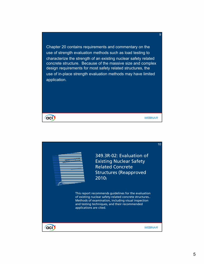
349.3R-02: Evaluation of Existing Nuclear Safety Related Concrete Structures (Reapproved 2010)
This report recommends guidelines for the evaluation of existing nuclear safety-related concrete structures.. Methods of examination, including visual inspection and testing techniques, and their recommended applications are cited.

6
WEBINAR
11
Analytical investigations: GeneralThorough field investigation shall be made of dimensions and details of
members, properties of materials, and other pertinent conditions
of the structure as actually built.
20.2-Determination of required dimensions and material properties
This section applies if it is decided to make an analytical evaluation.
Load tests: General20.3 Load tests are not confined to the complete concrete
structure; tests may be utilized to determine strength characteristics
of specific elements such as anchorages and embedments.
WEBINAR
• 20.5.2 Measured deflection shall satisfy Eq. (20-1) or (20-2) unless alternate deflection criteria are defined for the test:
•
•
12
7
WEBINAR
13
Provision for lower load rating
20.6 If the structure selected for investigation does not satisfty conditions of 20.1.2, 20.5.2, or 20.5.3, the structure shal be permitted for use as a lower load rating based on the results of load test load of analysis, if approved by licensed design professional and authority having jurisdication.
WEBINAR
14
SPECIAL DETAILS FOR SEISMIC FORCES
14Sec. 21.1

8
WEBINAR
Chapter 21 Provisions for Seismic DesignChapter 21 Provisions for Seismic Design15
WEBINAR
Chapter 21 Provisions for Seismic DesignChapter 21 Provisions for Seismic Design
Section 21.1
Elastic design under SSE (Response modification factor = 1)
Beyond Design Bases Event covered by ductile detailing similar to ACI 318 structures
Potential inelastic activity under impulsive and impactive loads – Appendix F
16

9
WEBINAR
Chapter 21 Provisions for Seismic DesignChapter 21 Provisions for Seismic Design
Section 21.1
Design Basis Earthquake (DBE) based on up to 10,000 year return period
Shearwalls and diaphragms – primary lateral load resisting systems
All Cat I structures have to be designed for Chapter 21
17
WEBINAR
ACI 349ACI 349
• The performance goal for facilities designed to ACI 349 is to achieve “safe shutdown” and maintain the facility in a safe condition.
• Consistent with the performance goal, design calls for “nearly elastic” behavior under DBE and “protection of workers, public and environment” under BDBE
18
10
WEBINAR
ACI 318ACI 318
• Response modification factors generally range from 3 to 8
• Structures designed to 318 are expected to maintain life-safety function; some inelastic deformation is expected
• Achieving appropriate levels of deformation capacity is emphasized
• The prescriptive rules are intended to deliver stable response during a DBE shaking
19
WEBINAR
20
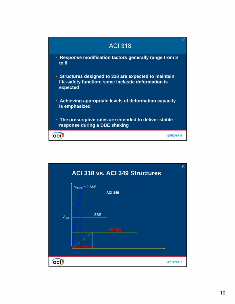
ACI 318 vs. ACI 349 Structures
VDBE
VBDBE = 2 SSE
ACI 349
ACI 318
SSE
20
11
WEBINAR
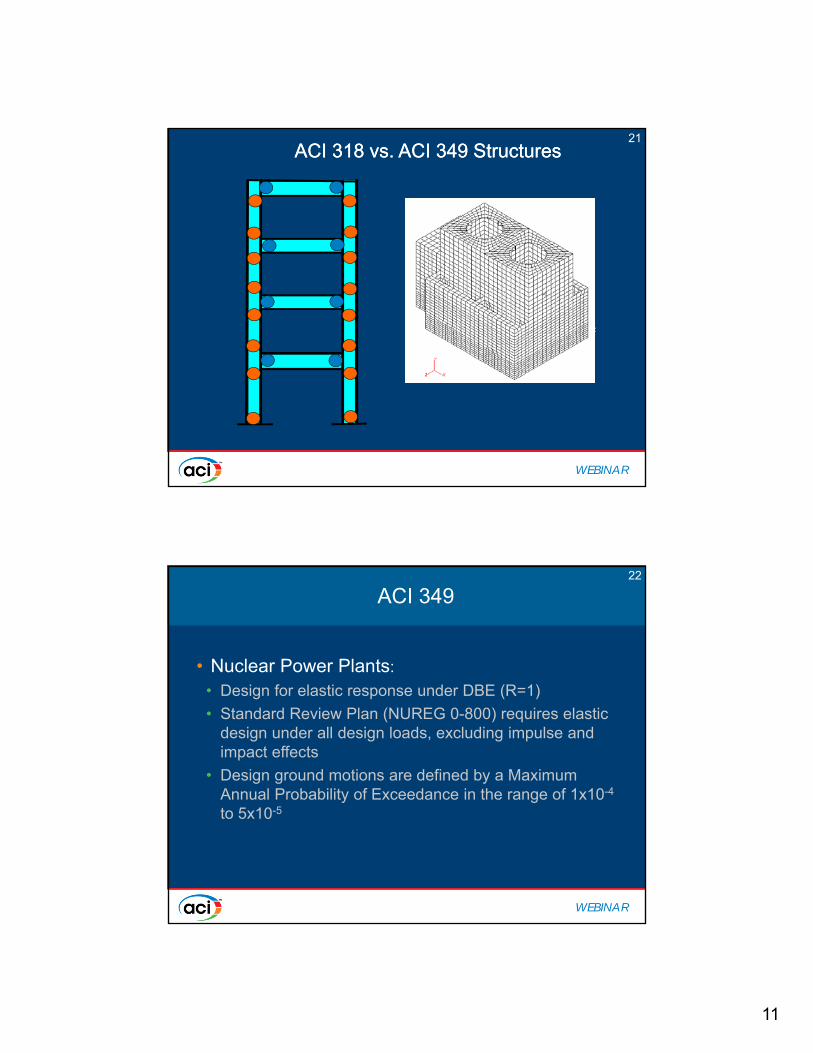
ACI 318 vs. ACI 349 StructuresACI 318 vs. ACI 349 Structures
Potential Plastic Hinges
21
WEBINAR
ACI 349ACI 349
• Nuclear Power Plants:
• Design for elastic response under DBE (R=1)
• Standard Review Plan (NUREG 0-800) requires elastic design under all design loads, excluding impulse and impact effects
• Design ground motions are defined by a Maximum Annual Probability of Exceedance in the range of 1x10⁻⁴
to 5x10⁻⁵
22

12
WEBINAR
ACI 349 (cont.)ACI 349 (cont.)
• DOE Facilities:– Design for elastic response reduced by an “energy
dissipation factor,” Fμ, which ranges from 1.5 to 2.75– In some cases Fμ cannot be more than 1.0 (e.g., out-of-
plane shear)– DBEs are generally based on seismic hazard levels of
5x10⁻⁴ to1x10-4
• For both types of facilities, safety must be maintained under the BDBE conditions
• No explicit evaluations are required for BDBE responses (at the moment)
23
WEBINAR
CHANGES MADE IN ACI 349-13CHANGES MADE IN ACI 349-13
• Only “moment frames” and “shear wall structures” are permitted
• Other structural systems are provided if “strength and toughness” equal to permitted systems are provided
• Commentary allows use of “energy dissipation factors” if permitted by the jurisdictional authority
• BDBE is introduced but level of shaking is not defined
24

13
WEBINAR
CHANGES MADE IN ACI 349-13 CHANGES MADE IN ACI 349-13
• Requirements for structural diaphragms revised eliminating chord reinforcement
• Use of higher strength rebar permitted:• 80 ksi for main reinforcement
• 100 ksi for confinement reinforcement
• Members below the base of the structure must be compatible with the seismic force-resisting system above the base
25
WEBINAR
Chapter 21 provisions for seismic designUpdate
Chapter 21 provisions for seismic designUpdate
21.1.2
All structural components that possess stiffness and strength in a NPP must be included in the mathematical model of the NPP.
26
14
WEBINAR
27
Detailing
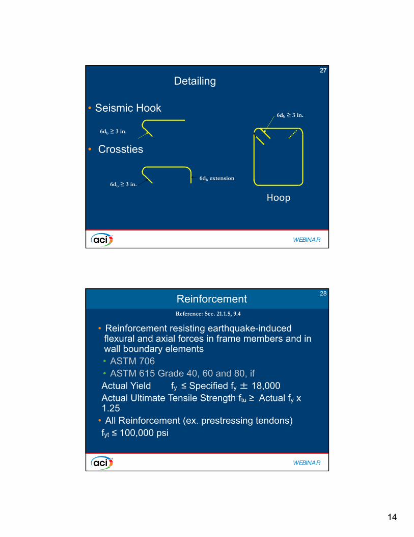
• Seismic Hook
• Crossties
6db ≥ 3 in.
6db ≥ 3 in.6db extension
Hoop
6db ≥ 3 in.
27
WEBINAR
ReinforcementReinforcement
• Reinforcement resisting earthquake-induced flexural and axial forces in frame members and in wall boundary elements • ASTM 706• ASTM 615 Grade 40, 60 and 80, if Actual Yield fy ≤ Specified fy ± 18,000Actual Ultimate Tensile Strength ftu ≥ Actual fy x 1.25
• All Reinforcement (ex. prestressing tendons)fyt ≤ 100,000 psi
Reference: Sec. 21.1.5, 9.4
28
15
WEBINAR
Reinforcement SplicesReinforcement Splices
• Mechanical Splices
• A full mechanical connection shall develop full tensile strength of the bar
• Welded Splices
• A full welded splice shall develop full tensile strength of the bar.
29
WEBINAR
30
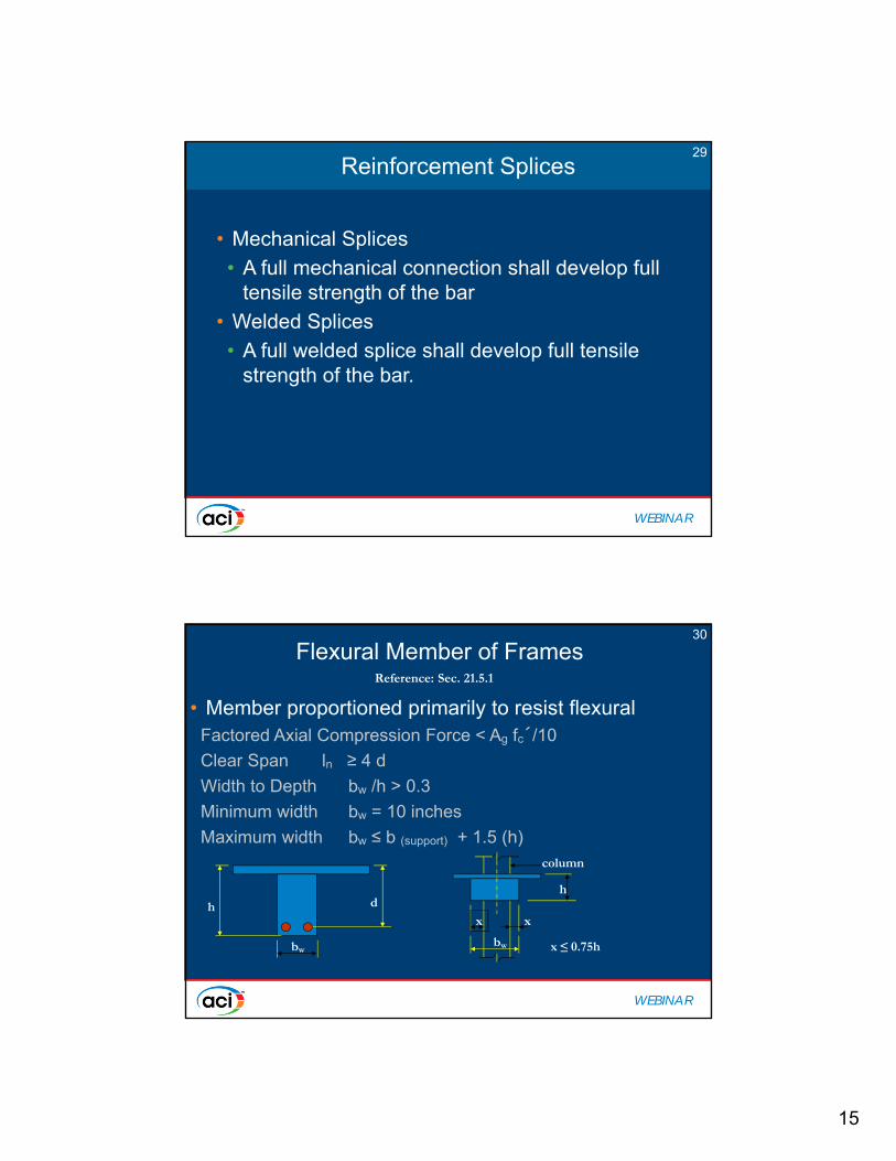
Flexural Member of Frames
• Member proportioned primarily to resist flexuralFactored Axial Compression Force < Ag fc´/10
Clear Span ln ≥ 4 d
Width to Depth bw /h > 0.3
Minimum width bw = 10 inches
Maximum width bw ≤ b (support) + 1.5 (h)
Reference: Sec. 21.5.1
h
bw
d
x x
h
bw
column
x ≤ 0.75h

16
WEBINAR
Flexural Member ReinforcementFlexural Member Reinforcement
• Longitudinal Reinforcement• Splices• Transverse Reinforcement
• Hoops • Stirrups or Ties
• Spacing of transverse reinforcement • First hoop at 2 inches from face of support• Maximum Spacing s ≤ d/4
s ≤ 8 db (smallest long. bar)
s ≤ 24 db (hoop)
s ≤ 12 inches
Reference: Sec. 21.5.2, 21.5.3
31
WEBINAR
32
Flexural Member Reinforcement
• Longitudinal ReinforcementMin. Top or Bott. Rebar As ≥ 200 bw d/fy
Maximum Steel Ratio = 0.025Minimum Number of Rebar = 2 min. cont. top & bott.Min. As at Joint face +As = 1/2 (- As) Min. As at any section ± As = 1/4 (As)max at Joint face
Reference: Sec. 21.5.2
-Mn1 -Mn2
+Mn1≥ -½Mn1 +Mn2≥ -½Mn2
-Mn or +Mn > Max ¼ Mn at either support
0.025bwd ≥ ± As ≥ 200 bw d/fy
Min. two bars cont.
Hoops not shown for clarity
- d +d

17
WEBINAR
33
Longitudinal Reinforcement Splices
• Location of lap Splices shall NOT be usedWithin the JointWithin distance = 2h from support faceAt Plastic Hinge Region
• Spacing s ≤ d/4 or 4 inches• Welded splices and mechanical connections to develop
full tensile strength
Reference: Sec. 21.5.2
≥ 2h
Hoopss ≤ d/4 or 4 inches
Splice outside plastic hinge region
h- d +d
WEBINAR
34
Flexural Member Reinforcement
• Transverse ReinforcementHoops are requiredOver Length = 2h from face of support at both ends Over Length = 2h both sides of plastic hinge regionAt JointRequired for calculated shear strengthStirrups or TiesWhen hoops are not requiredMaximum spacing = d/2
Reference: Sec. 21.5.3
2hs ≤ d/2
h
2”
s
s ≤ d/4
s ≤ 8 db (Longt’l bar)
s ≤ 8 db (Hoop ties)
s ≤ 12 inches
2h
Hoops
Stirrup tiess
- d

18
WEBINAR
Shear StrengthShear Strength
• Design Forces• Transverse Reinforcement
Reference: Sec. 21.5.4
35
WEBINAR
36Shear Strength
• Design ForcesVe = (Mpr1+Mpr2)/ln ± wuln/2 whereMpr = Probable Flexural Moment Strength
at joint face based on 1.25 fy and = 1
• Transverse ReinforcementVc = 0 whenVe ≥ one-half or more of total design shear andPu < Ag f ´c /20
Reference: Sec. 21.5.4
wu =1.2D+1.0L+0.2SMpr1 Mpr2
Ve
Shear diagram
Ve1 Ve2
ln
Beam shear
19
WEBINAR
37
Bending and Axial Loaded Member
• Frame Member subjected to Bending and Axial LoadResist earthquake induced forces, and Having a factored axial force Pu > Ag f ´c/10Dimension limitations b or h ≥ 12 inchesb/h or h/b ≥ 0.4
Reference: Sec. 21.6.1
b
h
WEBINAR
38
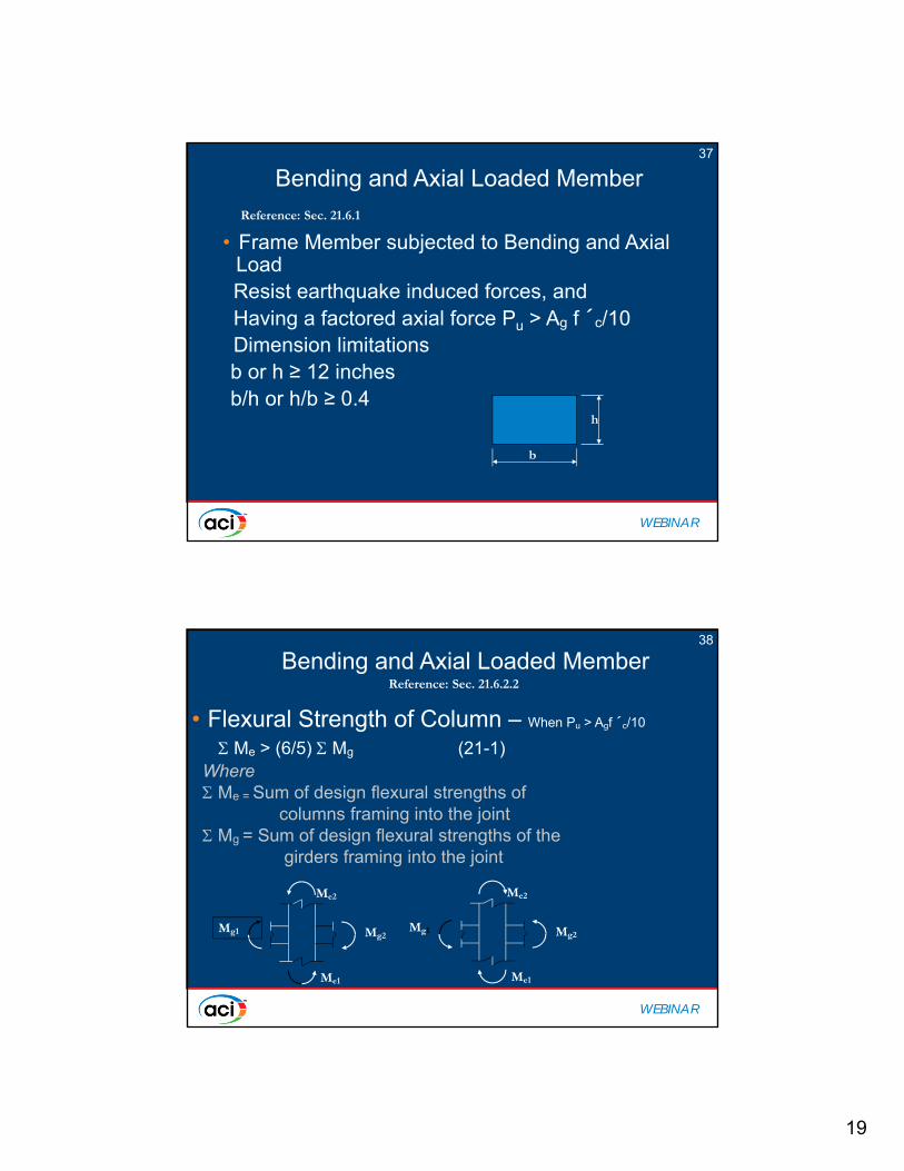
Bending and Axial Loaded Member
• Flexural Strength of Column – When Pu > Agf ´c/10
Me > (6/5) Mg (21-1)Where Me = Sum of design flexural strengths of
columns framing into the joint Mg = Sum of design flexural strengths of the
girders framing into the joint
Reference: Sec. 21.6.2.2
Mg1 Mg2
Me2
Me1
Mg1 Mg2
Me2
Me1

20
WEBINAR
39
Bending and Axial Loaded Member
• Longitudinal Reinforcement0.01 Ag ≤ st ≤ 0.06 Ag
Lap Splice of Longitudinal ReinforcementWithin center half of member lengthUse tension lap splice
Mechanical and Welded Splices (See 21.2.6)
Reference: Sec. 21.6.3
Tension lap splice
lo
lo
WEBINAR
40Bending and Axial Loaded Member
• Transverse ReinforcementRectangular HoopAsh = 0.30(sbc f ´c/f yt) [(Ag/Ach) – 1] (21-3)orAsh = 0.09 sbc f ´c/f yt (21-4)
Where
Ash = Total cross-sectional area of transverse reinforcement (including cross-ties) within spacing “s” and perpendicular to dimension bc
Rectangular HoopSingle or Overlapping HoopsCross Ties of same size as hoop secured to the peripheral hoop at 14 inches maximum on centerAlternate consecutive cross-ties end to end
Reference: Sec. 21.6.4
Hoop Cross tie
bc1
bc2
21
WEBINAR
41
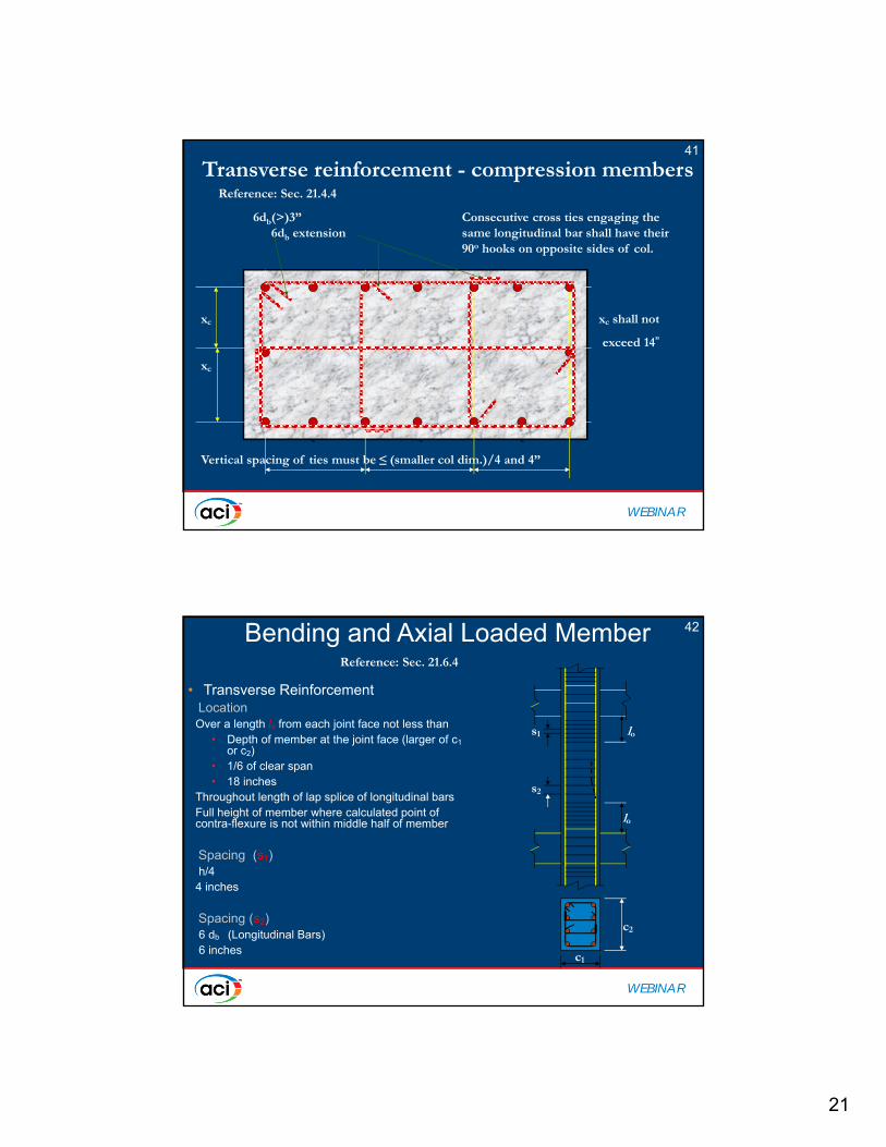
Transverse reinforcement - compression members
6db(>)3” Consecutive cross ties engaging the6db extension same longitudinal bar shall have their
90o hooks on opposite sides of col.
xc xc shall not
exceed 14”
xc
xc xc xc
Vertical spacing of ties must be ≤ (smaller col dim.)/4 and 4”
Reference: Sec. 21.4.4
WEBINAR
42Bending and Axial Loaded Member
• Transverse ReinforcementLocation Over a length lo from each joint face not less than
• Depth of member at the joint face (larger of c1or c2)
• 1/6 of clear span• 18 inches
Throughout length of lap splice of longitudinal barsFull height of member where calculated point of contra-flexure is not within middle half of member
Spacing (s1)h/4
4 inches
Spacing (s2) 6 db (Longitudinal Bars)6 inches
Reference: Sec. 21.6.4
lo
lo
s1
s2
c1
c2
22
WEBINAR
43Columns supporting Reaction from Discontinuous Stiff Member (Wall)
• Transverse Reinforcement over full height beneath level where discontinuity occurs if
Pu ≥ Ag f ´c/10• Extension of Transverse
ReinforcementDevelopment length, ld, of largest longitudinal barAt least 12 inches into footing or mat
Reference: Sec. 21.6.4.6
ld
≥12 in.
Structural wall
db open
Trans. Reinf.
WEBINAR
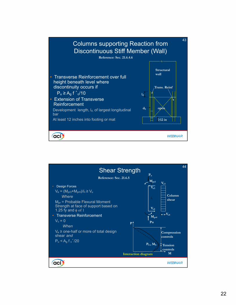
44Shear Strength
• Design Forces
Ve = (Mpr3+Mpr4)/ln ≥ Vu
WhereMpr = Probable Flexural Moment Strength at face of support based on 1.25 fy and of 1
• Transverse ReinforcementVc = 0
WhenVe ≥ one-half or more of total design shear andPu < Ag f c´/20
Reference: Sec. 21.6.5Pu
Mpr3
Ve3
Ve4
Mpr4
Pu
Column shear
Ve4
Ve3
ln
P
M
Pb , Mb
Compression controls
Tension controls
Interaction diagram
23
WEBINAR
Joints of FramesJoints of Frames
• Joint Considerations
• Stress in Flexural tensile reinforcement at 1.25 fy
• Strength Reduction Factor = 0.85
• Extend beam longitudinal reinforcement to far face of confined column core
• Minimum dimension parallel to beam reinforcement
h ≥ 20 db for normal weight concrete
Reference: Sec. 21.7
45
WEBINAR
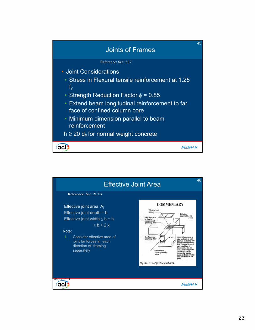
Effective Joint AreaEffective Joint Area
Effective joint area. Aj
Effective joint depth = h
Effective joint width ≤ b + h
≤ b + 2 x
Note:
1. Consider effective area of joint for forces in each direction of framing separately
46Sec. 21.1
Reference: Sec. 21.7.3
46

24
WEBINAR
47Joint Shear Strength
• Normal Shear Strength (Normal Wt. Concrete)For joints confined on all four faces 20fc´Aj
For joints confined on three faces 15fc´Aj
For joints confined on two opp. faces 15fc´Aj
For Others 12fc´Aj
• Design of joint
Reference: Sec. 21.7.3
Pu3
Pu4
T3=1.25fyAs
T4=1.25fyA's
As
A's
Mu3
Mu4
C4 = T3
C3 = T4
+Mpr-Mpr
Vh3
Vh4
Vjt= T3+C3 – Vh3
col
WEBINAR
Joint ConfinementJoint Confinement
• Provide Transverse Hoop Reinforcement
• Joint face is confined if all faces of joint is confined for at least ¾ of the face of the joint is covered by framing member. Spacing of confinement reinforcement may be 6 inches
• Transverse Reinforcement required through joint to provide confinement for longitudinal reinforcement outside column core if confinement is not provided by beam framing into joint
Reference: Sec. 21.7.2
48

25
WEBINAR
Development Length of Bars in TensionDevelopment Length of Bars in Tension
• Development Length for bars with standard 90 deg hook for normal weight concrete• ldh = fy db /(65/ (f´c) (21-6)
• 8 db
• 6 inches
Reference: Sec. 21.7.5.1
49
WEBINAR
Development Length of Bars in TensionDevelopment Length of Bars in Tension
• Development Length for Straight bars if the depth of concrete cast in one lift beneath does not exceed 12 inches.
• ldh = 2.5 fy db / (65/f´c)
• Otherwise the Development Length for Straight bars
• Ldh = 3.25 fy db / (65/f´c)
Reference: Sec. 21.7.5.2
50
26
WEBINAR
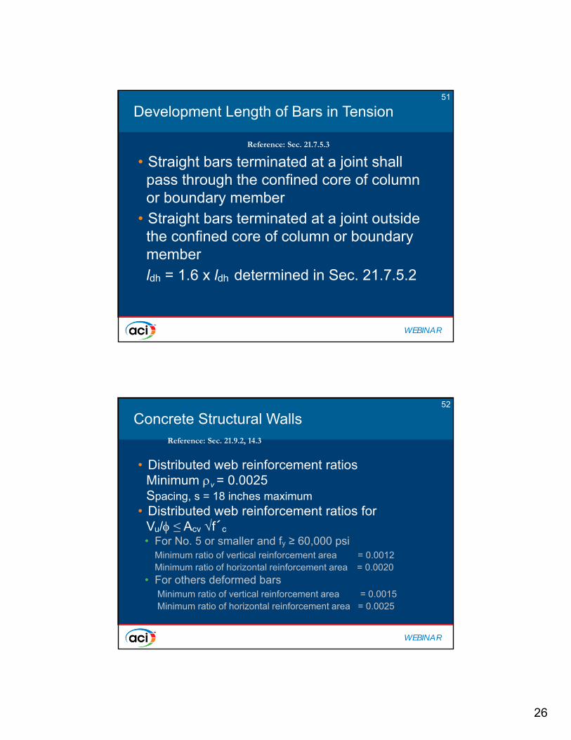
Development Length of Bars in TensionDevelopment Length of Bars in Tension
• Straight bars terminated at a joint shall pass through the confined core of column or boundary member
• Straight bars terminated at a joint outside the confined core of column or boundary memberldh = 1.6 x ldh determined in Sec. 21.7.5.2
Reference: Sec. 21.7.5.3
51
WEBINAR
Concrete Structural WallsConcrete Structural Walls
• Distributed web reinforcement ratiosMinimum v = 0.0025Spacing, s = 18 inches maximum
• Distributed web reinforcement ratios forVu/ ≤ Acv f´c
• For No. 5 or smaller and fy ≥ 60,000 psiMinimum ratio of vertical reinforcement area = 0.0012Minimum ratio of horizontal reinforcement area = 0.0020
• For others deformed barsMinimum ratio of vertical reinforcement area = 0.0015Minimum ratio of horizontal reinforcement area = 0.0025
Reference: Sec. 21.9.2, 14.3
52

27
WEBINAR
Structural WallsStructural Walls
Shear strength requirements per 21.9.4
Design for flexure and axial load per 21.9.5
s 18
s 18
Acv
53
WEBINAR
Concrete Structural WallsConcrete Structural Walls
• Distributed web reinforcement• USE double curtainVu/ > 2 Acv fc´
• Reinforcement shall be spliced for fyin tension
• Reinforcement shall be anchored in boundary element
• v ≥ n when hw/lw ≤ 2.0
Reference: Sec. 21.9.2.2, 21.9.2.4, 21.9.4.5, 21.9.5.4
54

28
WEBINAR
Concrete Structural WallsConcrete Structural Walls
• Shear Strength
Vn = Acv [ c f´c + n fy]Acv = h ( lw)Where c = 3.0 for hw/lw ≤ 1.5
c = 2.0 for hw/lw ≥ 2.0
Linear variation between 3.0 and 2.0 for hw/lw between 1.5 and 2.0
Reference: Sec. 21.9.4
(21-9)
1.0 1.5 2.0 2.51.5
2.0
2.5
3.0
hw/lw
c
55
WEBINAR
Structural Wall Shear StrengthStructural Wall Shear Strength
• Nominal Shear Strength
Vn ≤ 8 Acv f ´c
Where Acv = Acv (pier)
• Nominal Shear Strength for individual wall pier within pier group
Vn ≤ 10 Acw f ´c
Reference: Sec. 21.9.4
56

29
WEBINAR
Horizontal Wall SegmentHorizontal Wall Segment
• Nominal Shear StrengthVn ≤ 10 Acp f´c
WhereAcp = Cross-sectional area of horizontal wall segment
Reference: Sec. 21.9.4.
Horiz. wall segment
Note: openings should beConsidered in the design.
57
WEBINAR
Structural Wall –Design for Flexure and Axial Loads
Structural Wall –Design for Flexure and Axial Loads
• Based on Design Assumptions under Section 10.2• Based on General Principles and Requirements under
Section 10.3• Flexural Strength of wall segment - similar to procedures
commonly used for columns
Reference: Sec. 21.9.5
P
M
Pb , Mb
Compression controls
Tension controls
Interaction diagram
0
Po
Mo
58

30
WEBINAR
Reinforcement Details when Special Boundary Elements are Not Required
Reinforcement Details when Special Boundary Elements are Not Required
• Long. reinf. ratio at wall boundary > 430/fy• Transverse reinf. must satisfy
21.6.4.1(c), 21.6.4.3, and 21.9.6.4(a)• Maximum spacing of transverse
reinforcement in the boundary ≤ 10db
or 12 in.
(21.9.6.5)
59
WEBINAR
Reinforcement Details when Special Boundary Elements are Not Required
Reinforcement Details when Special Boundary Elements are Not Required
x
x
a
h
Acb = h(2x + a)
h
s
Acb = sh
Asb = area of long. reinf.in Acb
= Asb/ Acb
Ash
14”
s 10db or 12”
60
31
WEBINAR
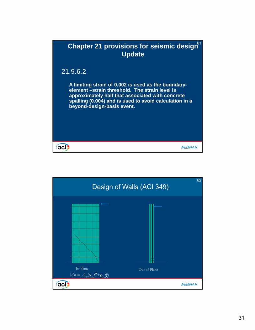
21.9.6.2
A limiting strain of 0.002 is used as the boundary-element –strain threshold. The strain level is approximately half that associated with concrete spalling (0.004) and is used to avoid calculation in a beyond-design-basis event.
Chapter 21 provisions for seismic designUpdate
61
WEBINAR
Design of Walls (ACI 349)Design of Walls (ACI 349)
In-Plane Out-of-Plane
Vn = Acv(αc fc′+ρt fy)
62
32
WEBINAR
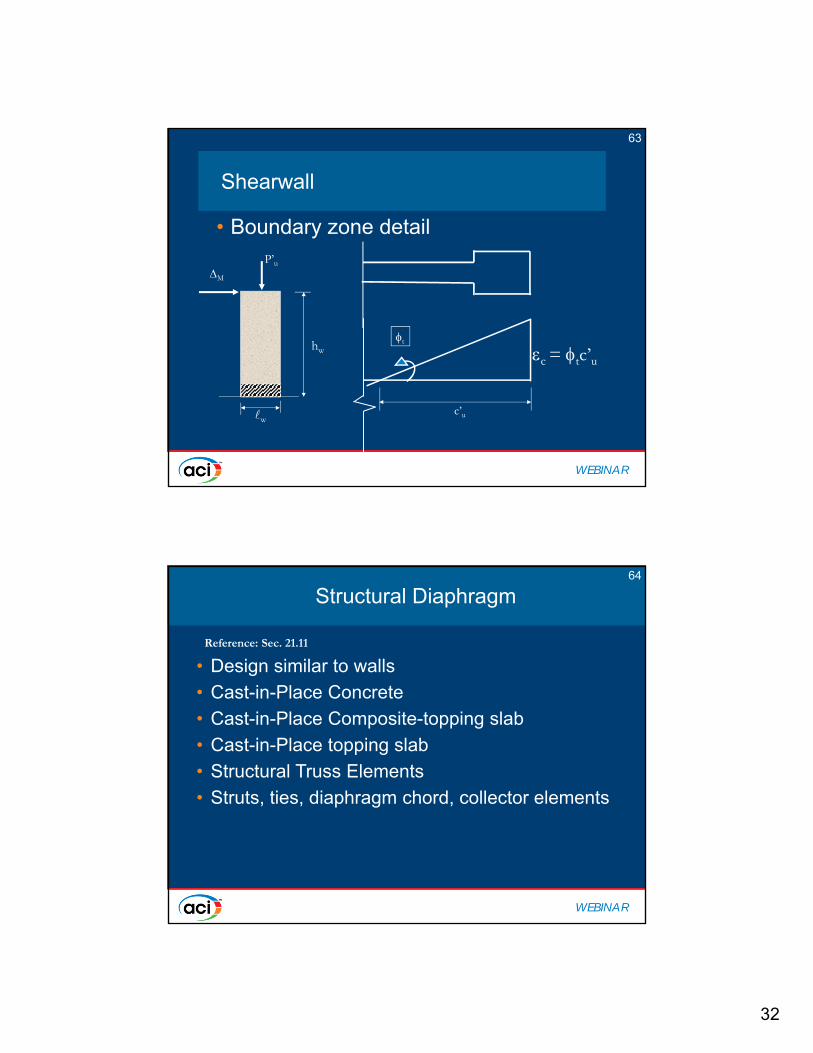
Shearwall Shearwall
• Boundary zone detail
c’u
t
c = tc’uhw
M
P’u
w
63
WEBINAR
Structural DiaphragmStructural Diaphragm
• Design similar to walls
• Cast-in-Place Concrete
• Cast-in-Place Composite-topping slab
• Cast-in-Place topping slab
• Structural Truss Elements
• Struts, ties, diaphragm chord, collector elements
Reference: Sec. 21.11
64
33
WEBINAR
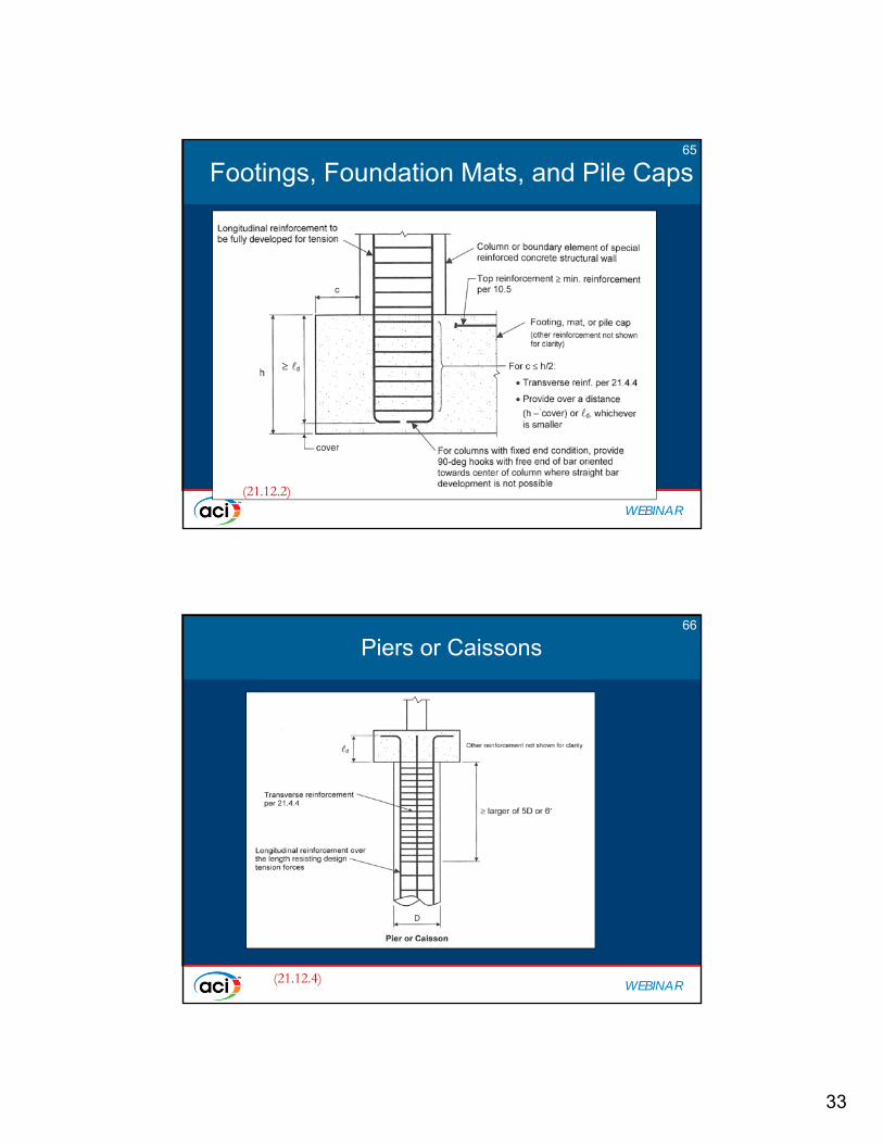
Footings, Foundation Mats, and Pile CapsFootings, Foundation Mats, and Pile Caps
(21.12.2)
65
WEBINAR
Piers or CaissonsPiers or Caissons
(21.12.4)
66

34
WEBINAR
Design ChallengesDesign Challenges
• Detailed Finite Element Models
• Two models• Static model
• SSI model
• Two step approach
• With thousands of load combinations and elements –large data processing effort
67
WEBINAR
Two Step AnalysesTwo Step Analyses
• Seismic SSI analyses are required for the design of safety-related, seismic category I structures.
• SSI analyses are regularly conducted using specialized computer codes such as SASSI2000,
• Standard structural codes such as GTSTRUDL, SAP2000 or ANSYS are used for the static load analyses.
• As a consequence, two set of independent results - seismic and static - must be used and combined during the design of seismic category I structures.
68

35
WEBINAR
How to combine results from two models?How to combine results from two models?
• 3 possible ways
• Equivalent static analysis
• Absolute peak element forces
• Time history of element forces
69
WEBINAR
• We need to be able to pick out the right kind of element level information and consolidate/interpret it in a manner that is compatible with the format of Code (ACI 349) requirements for:
– In-plane shear design– Sectional strength (Moment- axial interaction)– Out-of-plane bending and shear– Punching– Shear friction
How do we interpret the data?70

36
WEBINAR
And there are design dilemmasAnd there are design dilemmas
• Wall as a single entity or element-by-element design?
• Simultaneous in-plane and out-of-plane demands?
• What section cut length or element size is appropriate for in-plane and out-of-plane evaluations if discretized results are available?
• How should the interaction between the membrane and out-of-plane demands be accounted for?
71
WEBINAR
One ApproachOne Approach
i. Design for in-plane shear using full section cuts per ACI-349.
ii. Conduct local section reinforcement design in horizontal and vertical directions for P-M interaction effects; Sxx,|Mxx|+|Mxy| and Syy, |Myy|+|Mxy| respectively.
iii. Add the reinforcement from steps i and ii both in horizontal and vertical direction and check minimum reinforcement ratio.
72

37
WEBINAR
Thank you
For the most up-to-date information please visit the American Concrete Institute at:
www.concrete.org
END