code of conduct broadband equipment v3...
TRANSCRIPT
Broadband Equipment Code of Conduct – Version 3 18 November 2008
EUROPEAN COMMISSION DIRECTORATE-GENERAL JRC JOINT RESEARCH CENTRE Institute for the Energy Renewable Energy Unit
Ispra, 18 November 2008
Code of Conduct on Energy Consumption of Broadband Equipment
Version 3
18 November 2008

Broadband Equipment Code of Conduct - Version 3 21-Nov-08
2
INTRODUCTION
Expectations are that broadband equipment will contribute considerably to the electricity consumption of households in European Community in the near future. Depending on the penetration level, the specifications of the equipment and the requirements of the service provider, a total European consumption of up to 50 TWh per year can be estimated for the year 2015. With the general principles and actions resulting from the implementation of this Code of Conduct the (maximum) electricity consumption could be limited to 25 TWh per year, this is equivalent to 5,5 Millions tons of oil equivalent (TOE) and to total saving of about € 7,5 Billions per year.
The potential new electrical load represented by this equipment needs to be addressed by EU energy and environmental policies. It is important that the electrical efficiency of broadband equipment is maximised.
To help all parties to address the issue of energy efficiency whilst avoiding competitive pressures to raise energy consumption of equipment all service providers, network operators, equipment and component manufacturers are invited to sign this Code of Conduct.
This Code of Conduct sets out the basic principles to be followed by all parties involved in broadband equipment, operating in the European Community, in respect of energy efficient equipment.
HIGH-LEVEL DEFINITIONS
Full power state is the normal operating mode of the equipment or device where all design functionality is enabled and available for useful purposes.
Low power state(s) are modes of operation where the equipment or device has a level of operational functionality which is over and above the standby state, but not at a level associated with full power state (aka normal operation). These modes are normally defined in the component technology standards. ADSL2/2+ for example has two low power modes (L2 and L3). In L2 mode the ADSL2 transceiver is able to transport downstream user data at lower rates and lower consumed power than the normal (L0) mode where full power and data rate is available. L3 mode is associated with the standby state.
Standby state is defined as a state whereby the equipment or device is switched on and operating at the lowest level of power consumption, whilst still drawing energy from the mains. One or more internal functions or external interfaces (e.g. wired or wireless) may be effectively switched off. For example, in the case of an ADSL2/2+ based Router the DSL WAN side interface may be in the L3 mode (awaiting a wake up signal), and the WiFi interface switched off during the night (e.g. via an internal timer function set by the user).
Further supplementary definitions are also used in the main body of this Code of Conduct.

Broadband Equipment Code of Conduct - Version 3 21-Nov-08
3
1. EQUIPMENT COVERED
This Code of Conduct covers equipment for broadband services both on the customer side as listed in Table 1, and on the network side as listed in Table 2. Note that not all the equipment listed in these Tables may yet have a complete set of associated power targets (e.g. WiMax). Any such missing values may be added to future versions of the Code of Conduct, as may any additional technologies that become significant in the Broadband space. Figure 1 below gives examples of home gateway/modem configurations with the boundary between customer premises and network equipment that this Code of Conduct takes into account. Terminals like PCs, TVs are not covered by this Code of Conduct.
Figure 1. Examples of configurations
Home gateway
Consumer: End-use equipment
Network: Network equipment
Modem NT
Access line
LT
IP- network
Router LT
LT
Modem NT
Modem NT
Terminal(s)
HNID
HNID
ATA
Printer server
Broadband access equipment is defined by its incorporation of a transmission technology capable of providing more than 2048 kbit/s (ITU-T recommendation I.113 [1] ) full-rate capacity in at least one direction. When the equipment is in a low-power-state broadband services need to be offered to a user with almost the same quality and setup times as in on-state (note that this may or may not mean the various functional elements transitioning to full-power state). This requirement holds regardless of whether the service is initiated from the WAN-side, or the LAN-side.
In this Code of Conduct these categories of equipment will subsequently be referred to as “customer premises equipment” (CPE) and “network equipment” or “broadband equipment” in general.
Broadband Equipment Code of Conduct - Version 3 21-Nov-08
4
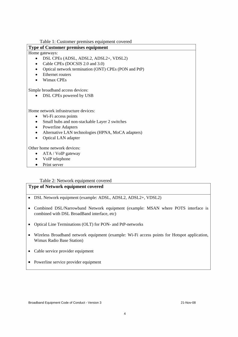
Table 1: Customer premises equipment covered Type of Customer premises equipment Home gateways:
• DSL CPEs (ADSL, ADSL2, ADSL2+, VDSL2) • Cable CPEs (DOCSIS 2.0 and 3.0) • Optical network termination (ONT) CPEs (PON and PtP) • Ethernet routers • Wimax CPEs
Simple broadband access devices:
• DSL CPEs powered by USB Home network infrastructure devices:
• Wi-Fi access points • Small hubs and non-stackable Layer 2 switches • Powerline Adapters • Alternative LAN technologies (HPNA, MoCA adapters) • Optical LAN adapter
Other home network devices: • ATA / VoIP gateway • VoIP telephone • Print server
Table 2: Network equipment covered Type of Network equipment covered
• DSL Network equipment (example: ADSL, ADSL2, ADSL2+, VDSL2)
• Combined DSL/Narrowband Network equipment (example: MSAN where POTS interface is combined with DSL BroadBand interface, etc)
• Optical Line Terminations (OLT) for PON- and PtP-networks
• Wireless Broadband network equipment (example: Wi-Fi access points for Hotspot application, Wimax Radio Base Station)
• Cable service provider equipment
• Powerline service provider equipment

Broadband Equipment Code of Conduct - Version 3 21-Nov-08
5
2. AIM
To target reduced energy consumption of broadband communication equipment without hampering the fast technological developments and the service provided.
Broadband Equipment Code of Conduct - Version 3 21-Nov-08
6
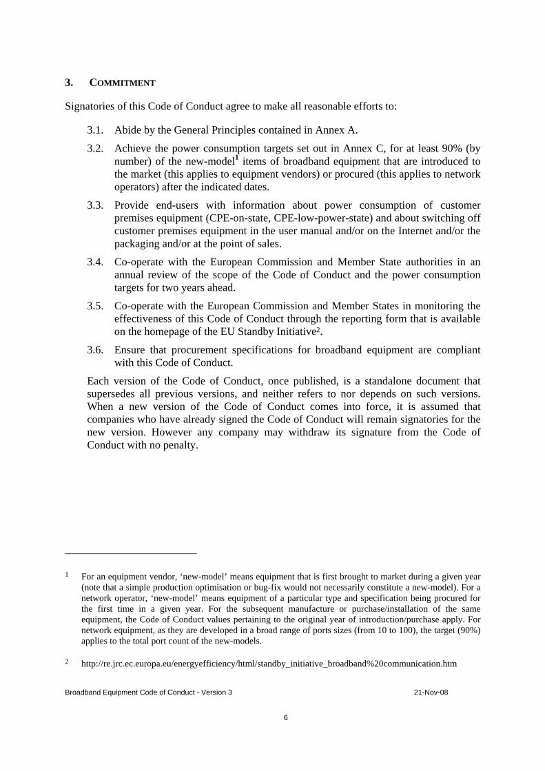
3. COMMITMENT
Signatories of this Code of Conduct agree to make all reasonable efforts to:
3.1. Abide by the General Principles contained in Annex A.
3.2. Achieve the power consumption targets set out in Annex C, for at least 90% (by number) of the new-model1 items of broadband equipment that are introduced to the market (this applies to equipment vendors) or procured (this applies to network operators) after the indicated dates.
3.3. Provide end-users with information about power consumption of customer premises equipment (CPE-on-state, CPE-low-power-state) and about switching off customer premises equipment in the user manual and/or on the Internet and/or the packaging and/or at the point of sales.
3.4. Co-operate with the European Commission and Member State authorities in an annual review of the scope of the Code of Conduct and the power consumption targets for two years ahead.
3.5. Co-operate with the European Commission and Member States in monitoring the effectiveness of this Code of Conduct through the reporting form that is available on the homepage of the EU Standby Initiative2.
3.6. Ensure that procurement specifications for broadband equipment are compliant with this Code of Conduct.
Each version of the Code of Conduct, once published, is a standalone document that supersedes all previous versions, and neither refers to nor depends on such versions. When a new version of the Code of Conduct comes into force, it is assumed that companies who have already signed the Code of Conduct will remain signatories for the new version. However any company may withdraw its signature from the Code of Conduct with no penalty.
1 For an equipment vendor, ‘new-model’ means equipment that is first brought to market during a given year (note that a simple production optimisation or bug-fix would not necessarily constitute a new-model). For a network operator, ‘new-model’ means equipment of a particular type and specification being procured for the first time in a given year. For the subsequent manufacture or purchase/installation of the same equipment, the Code of Conduct values pertaining to the original year of introduction/purchase apply. For network equipment, as they are developed in a broad range of ports sizes (from 10 to 100), the target (90%) applies to the total port count of the new-models.
2 http://re.jrc.ec.europa.eu/energyefficiency/html/standby_initiative_broadband%20communication.htm

Broadband Equipment Code of Conduct - Version 3 21-Nov-08
7
MONITORING
Signatories agree to provide to the European Commission on a yearly basis, starting with the year of the signing of the Code of Conduct, by the end of February of the following year, information concerning the power consumption of the equipment covered by the Code of Conduct they produce, specify, buy, or install etc.
The reported results will be discussed starting with the year of the signing of the Code of Conduct at least once a year in a confidential and anonymous way by the signatories, the European Commission, Member States and their representatives in order to:
a) Evaluate the level of compliance and the effectiveness of this Code of Conduct in achieving its aims.
b) Evaluate current and future developments that influence energy consumption, (i.e. Integrated Circuit development, etc.) with a view to agreeing actions and/or amendments to the Code of Conduct.
c) Set targets for future time periods.
Reporting: The presentation of the results provided to the Commission will be in the form of the Reporting sheet available on the homepage of the EU Stand-by Initiative [3].

Broadband Equipment Code of Conduct - Version 3 21-Nov-08
8
Annex A – General Principles
Signatories of this Code of Conduct should endeavour to make all reasonable efforts to ensure:
For broadband equipment in general
A.1 Broadband equipment should be designed to meet the CoC power consumption targets. However power management must not unduly impact the user experience, disturb the network, or contravene the applicable standards.
A.2 Operational and control systems are specified on the presumption that hardware has power management built in, where applicable, i.e. depending on the functionality required of the unit, the hardware will automatically switch to the state with the lowest possible power consumption.3
For customer premises equipment
A.3 Any external power supplies used for customer premises equipment shall be in accordance with the EU Code of Conduct for External Power Supplies [4]. Power consumption of the external power supply shall be included in the power measurement.
A.4 Customer premises equipment is designed on the assumption that the equipment may be physically disconnected from the mains or switched off manually by the customer, from time to time, at his or her discretion. Even though an on/off switch is not a requirement of this Code of Conduct, it is highly recommended to integrate one into equipment. A fast and dependable start-up and re-entry into operating state has to be guaranteed.
A.5 Power delivered to other equipment (e.g. over USB or PoE) shall not be included in the power consumption assessment. This further equipment shall be disconnected for the power consumption measurement, except when this is in contradiction with the operation of the product.
For network equipment
A.6 Broadband Network equipment should be designed to fulfil the environmental specifications of Class 3.1 for indoor use and even more extended environmental conditions than Class 3.1 for use at remote sites according to the ETSI Standard EN 300019-1-3 [5]. If cooling is necessary it should be preferably cooled with fresh air (fan driven, no refrigeration). The COP (Coefficient Of Performance) of new site cooling systems, defined as the ratio of the effective required cooling power to the energy needed for the cooling system, should be more than 10.
3 For DSL systems, this function will have to be activated when concerns about problems related to the non-stationary noise have been solved. To this end signatories will endeavour to develop the necessary standards. Until then a special focus is put on the reduction of the power consumption in DSL-full power state.

Broadband Equipment Code of Conduct - Version 3 21-Nov-08
9
Annex B – Definition of operation states
B.1. Definitions of CPE operation states
Off-state:
In the off-state the device is not providing any functionality. This state is entered when the CPE is switched off or when it is disconnected from the mains. The only possible power consumption remaining is due to the power supply which should comply with the Code of Conduct for External Power Supplies [4]. The equipment can only leave this state by being switched on manually.
Low-power-state:
In the low-power-state the device is idle, with all the components being in their individual low-power states. In this state the device is not processing or transmitting a significant amount of traffic, but is ready to detect activity.
The low-power-state of a home gateway is defined as all the components of the home gateway being in their low-power-state as defined in Table 3.
Table 3: Definition of the low-power-state for home gateways
Port / component Low-power-state
Central functions (processor and memory: routing, firewall, OAM (e.g. TR-069), user interface)
Not processing user traffic
WAN interface Idle (link established, but no user traffic transmission)
LAN Ethernet ports Ports not connected (or no Ethernet link) but with Ethernet link detection active
Wi-Fi Beacon on, but no user traffic transmitted
Alternative LAN technologies (HPNA, MoCA, Powerline, POF…)
MoCA, Powerline, HPNA or POF capability is activated, but no user traffic transmitted
FXS 1 phone connected, on hook. Off hook detection active. If there are multiple FXS ports only 1 is connected.
FXO No active call , incoming call detection enabled

Broadband Equipment Code of Conduct - Version 3 21-Nov-08
10
DECT interface No active call , incoming call detection enabled
DECT charging station for DECT handset
DECT handset on cradle, in trickle charge
USB No devices connected, detection of USB devices active
When activity is detected on a component the appropriate components transition to the on-state. The transition time should be less than 1 second wherever possible in order to not adversely impact the customer experience. The detection of the Ethernet link may take more than 1 second, but must stay below 3 seconds. This longer transition time can be tolerated in this case because it requires some user interaction to bring up the link (e.g. connect a device or boot a PC).
Note that because only those components required to support the activated service go into their on-state, for a complete device (as opposed to a functional component) there will in fact be a range of power states. At any given time the CPE should consume the minimum power commensurate with its current level of activity (with the appropriate hysteresis).
Table 4: Definition of the low-power-state for Home Network Infrastructure Devices (HNID)
Port / component Low-power-state
Ethernet port Port idle (connected, but no user traffic transmission), cable length = 5m
Wi-Fi Beacon on, no user traffic transmitted
Alternative LAN technologies (HPNA, MoCA, Powerline, optical LAN adapters …) interface
No user traffic being transmitted
Table 5: Definition of the low-power-state for other home networking devices
Port / component Low-power-state
Ethernet port Port idle (connected, but no user traffic transmission), cable length = 5m
VoIP/telephony No active call , call detection active, inactive display
Print server No print job active

Broadband Equipment Code of Conduct - Version 3 21-Nov-08
11
On-state:
The on-state of a home gateway is defined as all the components of the home gateway being in their on-state as defined in Table 6. For the interfaces carrying user traffic a throughput of 25% of the available bandwidth in both directions (i.e. 25% Tx and 25% Rx) is to be considered.
Table 6: Definition of the on-state for home gateways
Port / component On-state
Central functions (processor and memory: routing, firewall, OAM (e.g. TR-069), user interface)
Processing typical level of user traffic
WAN port Active (link established at full line rate and passing user traffic)
LAN Ethernet ports All 4 ports active (link established at max rate and passing user traffic), cable length=5m
Wi-Fi Beacon on, with user traffic
Alternative LAN technologies (HPNA, MoCA, Powerline, POF…)
MoCA, Powerline, HPNA or POF capability is activated, with user traffic transmitted
FXS 1 phone connected, off hook, 1 active call. If there are multiple FXS ports only 1 is connected.
FXO 1 active call
DECT interface 1 active call
DECT charging station for DECT handset
DECT handset not on cradle, no charging
USB No USB device connected, detection of USB devices active
Table 7: Definition of the on-state for Home Network Infrastructure Devices (HNID)
Broadband Equipment Code of Conduct - Version 3 21-Nov-08
12
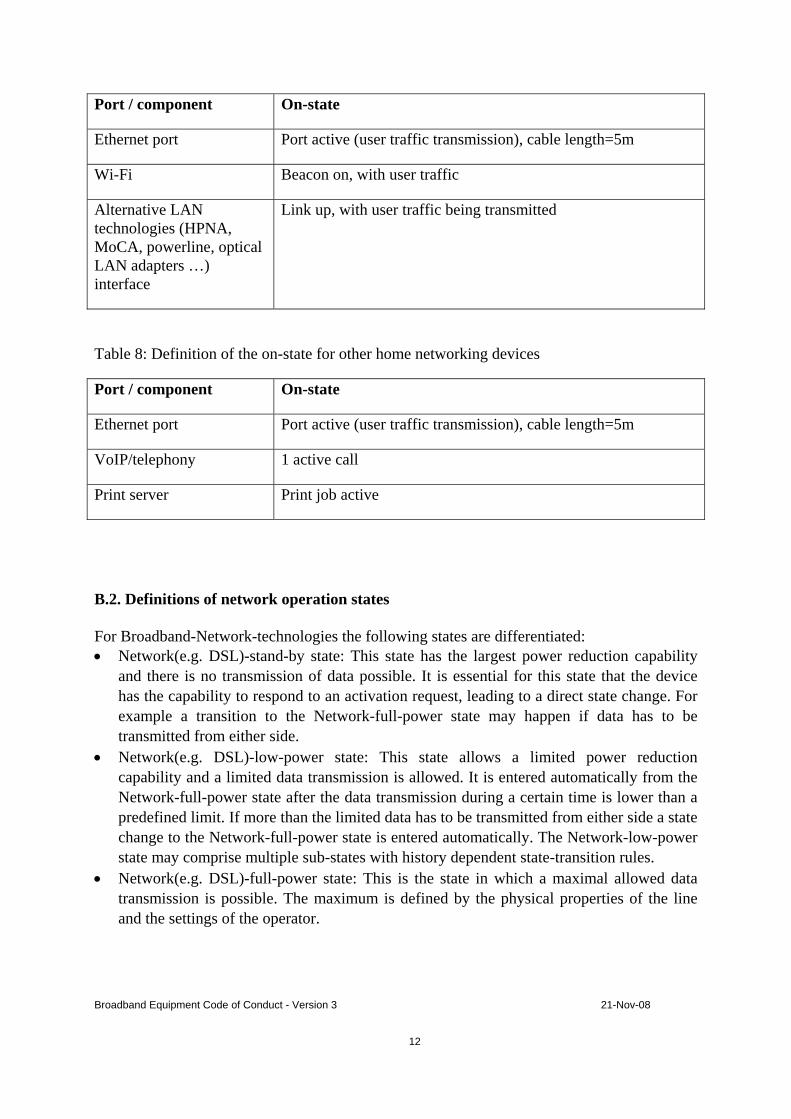
Port / component On-state
Ethernet port Port active (user traffic transmission), cable length=5m
Wi-Fi Beacon on, with user traffic
Alternative LAN technologies (HPNA, MoCA, powerline, optical LAN adapters …) interface
Link up, with user traffic being transmitted
Table 8: Definition of the on-state for other home networking devices
Port / component On-state
Ethernet port Port active (user traffic transmission), cable length=5m
VoIP/telephony 1 active call
Print server Print job active
B.2. Definitions of network operation states For Broadband-Network-technologies the following states are differentiated: • Network(e.g. DSL)-stand-by state: This state has the largest power reduction capability
and there is no transmission of data possible. It is essential for this state that the device has the capability to respond to an activation request, leading to a direct state change. For example a transition to the Network-full-power state may happen if data has to be transmitted from either side.
• Network(e.g. DSL)-low-power state: This state allows a limited power reduction capability and a limited data transmission is allowed. It is entered automatically from the Network-full-power state after the data transmission during a certain time is lower than a predefined limit. If more than the limited data has to be transmitted from either side a state change to the Network-full-power state is entered automatically. The Network-low-power state may comprise multiple sub-states with history dependent state-transition rules.
• Network(e.g. DSL)-full-power state: This is the state in which a maximal allowed data transmission is possible. The maximum is defined by the physical properties of the line and the settings of the operator.

Broadband Equipment Code of Conduct - Version 3 21-Nov-08
13
Annex C – Power levels: targets and time schedule
C.1. Customer premises equipment
The customer premises equipment covered by this Code of Conduct (home gateways, home network infrastructure devices and other home network devices) should meet the following maximum power consumption targets in the on-state and in the low-power-state (as defined in section B.1). In the off-state it must meet the requirements of the Code of Conduct for External Power Supplies [4].
The equipment should apply all possible energy saving actions, minimizing the overall power consumption whenever possible (e.g. when all or some of its functions are not operating).
The power levels in this document for all states are mean values based on sufficiently long measurement periods during which the equipment remains continuously in that same state. Power is measured at the 230V AC input.
C.1.1 Home Gateways
The home gateway4 is composed of several components, namely a processor plus memory, a WAN interface and several LAN interfaces. Depending on the purpose of a given home gateway different components may be included. The power consumption targets for each type of home gateway are calculated by summing the values of its individual components. The home gateway as a whole has to meet the summed targets for its various modes of operation and activity. Component power consumption values are used to compute the overall home gateway target for a given configuration and mode of operation, but are not themselves normative.
The home gateway must meet the power targets for low-power-state and for on-state as defined in section B.1. Depending on the actual state of the individual components, several intermediate power consumption levels for the home gateway exist.
The values per component for the low-power-state and the on-state are given in the following tables.
4 A home gateway is used here as a generic term which encompasses all kinds of access interfaces (e.g. DSL, cable, fibre, etc.)

Broadband Equipment Code of Conduct - Version 3 21-Nov-08
14
Table 9: Power values for home gateway central functions plus WAN interface
Tier 2009/2010: 1.1.2009- 31.12.2010
Tier 2011: 1.1.- 31.12.2011
Home gateway central functions plus WAN interface
Low-Power-State (W)
On-State (W)
Low-Power-State (W)
On-State (W)
ADSL/ADSL2/ADSL2+ 4,2 5,0 2,6 3,8
VDSL2 5,5 7,5 3.5 6,0
Fast Ethernet WAN (100Base-T) 2,9 4,2 2,5 3,3
Gigabit Ethernet WAN (1000Base-T) 4,0 7,0 3,2 6,2
Fibre Ptp Ethernet WAN (100/1000Base-BX or FX)
3,4 7,1 2,9 5,6
GPON 5,0 9,7 4,0 7,7
DOCSIS 2.0 5,5 5,5 3,7 4,6
DOCSIS 3.0 8,0 8,0 6,2 7,1
WiMAX 8,2 11,0 7,7 10,6
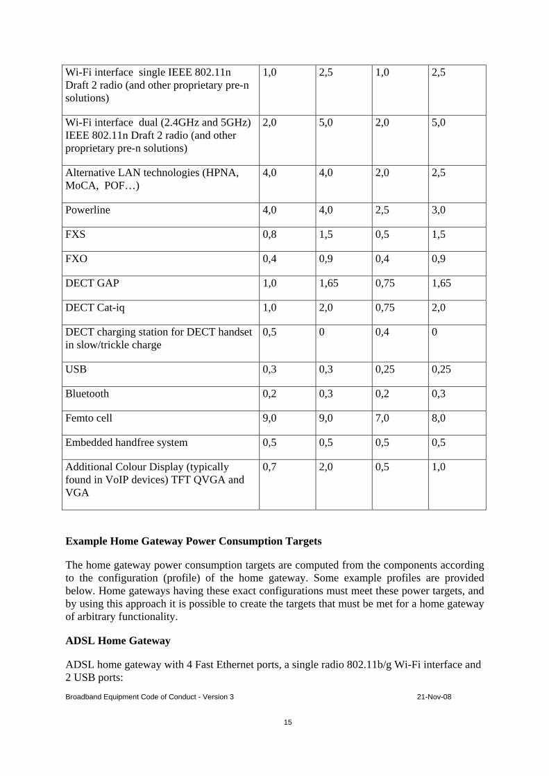
Table 10: Power values for home gateway LAN interfaces and additional functionality
Tier 2009/2010: 1.1.2009- 31.12.2010
Tier 2011: 1.1.- 31.12.2011
Home gateway LAN interfaces and additional functionality
Low-Power-State (W)
On-State (W)
Low-Power-State (W)
On-State (W)
Fast Ethernet switch, up to 4 ports 0,8 2,2 0,6 1,8
1 Fast Ethernet port 0,3 0,5 0,3 0,4
Gigabit Ethernet switch, up to 4 ports 1,5 4,5 1,2 3,7
1 Gigabit Ethernet port 0,3 1,7 0,3 1,3
Wi-Fi interface single IEEE 802.11b/g or 11a radio
1,0 2,0 0,7 2,0
Broadband Equipment Code of Conduct - Version 3 21-Nov-08
15
Wi-Fi interface single IEEE 802.11n Draft 2 radio (and other proprietary pre-n solutions)
1,0 2,5 1,0 2,5
Wi-Fi interface dual (2.4GHz and 5GHz) IEEE 802.11n Draft 2 radio (and other proprietary pre-n solutions)
2,0 5,0 2,0 5,0
Alternative LAN technologies (HPNA, MoCA, POF…)
4,0 4,0 2,0 2,5
Powerline 4,0 4,0 2,5 3,0
FXS 0,8 1,5 0,5 1,5
FXO 0,4 0,9 0,4 0,9
DECT GAP 1,0 1,65 0,75 1,65
DECT Cat-iq 1,0 2,0 0,75 2,0
DECT charging station for DECT handset in slow/trickle charge
0,5 0 0,4 0
USB 0,3 0,3 0,25 0,25
Bluetooth 0,2 0,3 0,2 0,3
Femto cell 9,0 9,0 7,0 8,0
Embedded handfree system 0,5 0,5 0,5 0,5
Additional Colour Display (typically found in VoIP devices) TFT QVGA and VGA
0,7 2,0 0,5 1,0
Example Home Gateway Power Consumption Targets
The home gateway power consumption targets are computed from the components according to the configuration (profile) of the home gateway. Some example profiles are provided below. Home gateways having these exact configurations must meet these power targets, and by using this approach it is possible to create the targets that must be met for a home gateway of arbitrary functionality.
ADSL Home Gateway
ADSL home gateway with 4 Fast Ethernet ports, a single radio 802.11b/g Wi-Fi interface and 2 USB ports:

Broadband Equipment Code of Conduct - Version 3 21-Nov-08
16
- in low-power-state: all Ethernet ports disconnected, no traffic on Wi-Fi
- in on-state: all Ethernet ports active, traffic on Wi-Fi
low-power-state on-state Function
2009/2010 2011 2009/2010 2011
Central functions + ADSL WAN interface
4,2 2,6 5,0 3,8
4 port Ethernet switch 0,8 0,6 2,2 1,8
single radio IEEE 802.11b/g Wi-Fi interface
1,0 0,7 2,0 2,0
USB ports 0,3x2 0,25x2 0,3x2 0,25x2
Total equipment 6,6 W 4,4 W 9,8 W 8,1 W
VDSL2 Home Gateway
VDSL2 home gateway with 4 Fast Ethernet ports, a single radio 802.11n Wi-Fi interface, 2 USB ports and 1 FXS port:
- in low-power-state: all Ethernet ports disconnected, no traffic on Wi-Fi, no active voice call
- in on-state: all Ethernet ports active, traffic on Wi-Fi, 1 active voice call
low-power-state on-state Function
2009/2010 2011 2009/2010 2011
Central functions + VDSL2 WAN interface
5,5 3,5 7,5 6,0
4 port Ethernet switch 0,8 0,6 2,2 1,8
single IEEE 802.11n Draft 2 radio Wi-Fi interface
1,0 1,0 2,5 2,5

Broadband Equipment Code of Conduct - Version 3 21-Nov-08
17
USB ports 0,3x2 0,25x2 0,3x2 0,25x2
FXS ports 0,8 0,5 1,5 1,5
Total equipment 8,3 W 6,1 W 14,3 W 12,3 W
Ethernet router with 4 Fast Ethernet LAN ports
Fast Ethernet router with 1 WAN and 4 LAN Ethernet ports:
- in low-power-state: all LAN Ethernet ports disconnected
- in on-state: all LAN Ethernet ports active
low-power-state on-state Function
2009/2010 2011 2009/2010 2011
Central functions + Fast Ethernet WAN interface
2,9 2,5 4,2 3,3
4 port Fast Ethernet switch
0,8 0,6 2,2 1,8
Total equipment 3,7 W 3,1 W 6,4 W 5,1 W
Simple Cable DOCSIS 2.0 CPE
DOCSIS 2.0 CPE with 1 Fast Ethernet port:
- in low-power-state: the Ethernet port is disconnected
- in on-state: the Ethernet port is active
low-power-state on-state Function
2009/2010 2011 2009/2010 2011
Central functions + DOCSIS 2.0 WAN interface
5,5 3,7 5,5 4,6
Broadband Equipment Code of Conduct - Version 3 21-Nov-08
18
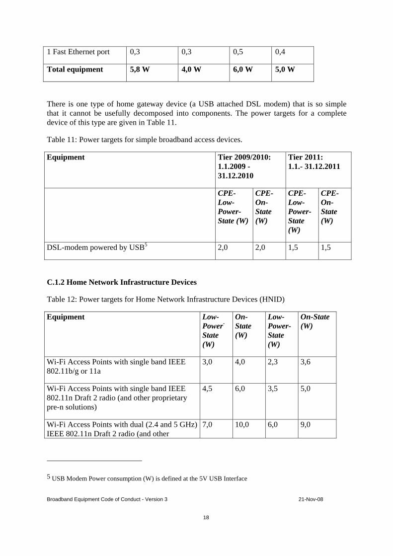
1 Fast Ethernet port 0,3 0,3 0,5 0,4
Total equipment 5,8 W 4,0 W 6,0 W 5,0 W
There is one type of home gateway device (a USB attached DSL modem) that is so simple that it cannot be usefully decomposed into components. The power targets for a complete device of this type are given in Table 11.
Table 11: Power targets for simple broadband access devices.
Equipment Tier 2009/2010: 1.1.2009 - 31.12.2010
Tier 2011: 1.1.- 31.12.2011
CPE-Low-Power-State (W)
CPE-On-State (W)
CPE-Low-Power-State (W)
CPE-On-State (W)
DSL-modem powered by USB5 2,0 2,0 1,5 1,5
C.1.2 Home Network Infrastructure Devices
Table 12: Power targets for Home Network Infrastructure Devices (HNID)
Equipment Low-Power-
State (W)
On-State (W)
Low-Power-State (W)
On-State (W)
Wi-Fi Access Points with single band IEEE 802.11b/g or 11a
3,0 4,0 2,3 3,6
Wi-Fi Access Points with single band IEEE 802.11n Draft 2 radio (and other proprietary pre-n solutions)
4,5 6,0 3,5 5,0
Wi-Fi Access Points with dual (2.4 and 5 GHz) IEEE 802.11n Draft 2 radio (and other
7,0 10,0 6,0 9,0
5 USB Modem Power consumption (W) is defined at the 5V USB Interface

Broadband Equipment Code of Conduct - Version 3 21-Nov-08
19
proprietary pre-n solutions)
Small hubs and non-stackable Layer 2 switches (up to 8 Ethernet 10/100/1000 ports) without CPU (no VPN or VoIP)
3.0 8,0 2.5 7.0
Optical LAN adapter (fiber converter) 10/100/1000 Mbit/s
4,0 4,0 3,5 3,5
Powerline adapters 4,5 5,0 3,5 4,5
Alternative LAN technologies (HPNA, MoCA, powerline adapters …)
5,0 5,0 4,5 4,5
An HNID is typically a relatively simple device, but for more complex HNIDs the same allowances for additional functionality apply as for home gateways (see Table 10).
C.1.3 Other Home Network Devices
Table 13: Power targets for other home network devices
Equipment Low-Power-State
(W)
On-State (W)
Low-Power-State
(W)
On-State (W)
ATA / VoIP gateway 2,0 2,7 1,5 2,2
VoIP telephone 3,5 4,2 3,0 3,7
Print server (without Wi-Fi) 3,0 4,5 2,0 4,0
Some types of other home network devices require additional functionality; in that case the same allowances for additional functionality apply as for home gateways (see Table 10).

Broadband Equipment Code of Conduct - Version 3 21-Nov-08
20
C.2 Network equipment
The following targets are power consumption targets per port.
a) All power values measured at the “A” interface as described in the standard ETSI 102 533 [8] or at the AC input, in case of directly mains powered systems. For directly mains powered systems, the power limits stated in Table 14 through Table 20, will be increased by 10%.
b) The stated target figures apply for equipment operating in their native modes only. In other words, the targets for ADSL2+ equipment apply for equipment that are designed to operate natively in ADSL2+ mode and not VDSL2 equipment operating in ADSL2+ Fallback mode.
C.2.1 Broadband DSL Network equipment
Table 14: Broadband ports – DSL-full-power-state Equipment Tier 2009-2010
(1.1.2009-31.12.2010) (W)
Tier 2011 (1.1.2011-31.12.2011)
(W)
ADSL 2+ (including ADSL and ADSL2 and with transmission power of 19,8 dBm)
1,3 1,2
VDSL2 (profile 8b) 2,0 1,8
VDSL2 (profile 12a and 17a) 1,8 1,6
VDSL2 (profile 30a) 2,5 2,0
The above values are for fully equipped with maximum configuration DSLAMs with more than 100 ports. For equipment up to 100 ports (and with maximum configuration) 0,3 W per line may be added to the above values, with a minimum value of 10 W for the whole DSLAM. The additional allowance for the uplink interface (which is applicable for all Power States (Full, Low & Standby) is:
• 4,5W per equipment for each Point to Point 1000Mbit/s interface • 18W per equipment for each Point to Point 10Gbit/s interface • 6W per equipment for each Point to Multipoint (GPON) interface

Broadband Equipment Code of Conduct - Version 3 21-Nov-08
21
Table 15: Broadband ports – DSL-low power state6 Equipment Tier 2009-2010
(1.1.2009-31.12.2010) (W)
Tier 2011 (1.1.2011-31.12.2011)
(W)
ADSL 2+ (including ADSL2) 1,1 0,8
VDSL2 7 -- 1,2
Start-up/Wake-up times from DSL-low-power-state to DSL-full-power-state should be less than 1 second to guarantee a good quality of service (e.g. voice calls).
Table 16: Broadband ports – DSL-standby-state 8 Equipment Tier 2009-2010
(1.1.2009-31.12.2010) (W)
Tier 2011 (1.1.2011-31.12.2011)
(W))
ADSL 2+ (including ADSL and ADSL2) 0,4 0,4
VDSL2 0,8 0,6
The above values for DSL-low-power- and -standby-states are for fully equipped with maximum configuration for DSLAMs with more than 100 ports. For equipment up to 100 ports (and with maximum configuration) 0,3W per line may be added to the above values for the whole DSLAM, with a minimum value of 10W
6 The DSL-Low Power State should allow a bit rate of a configurable value (e.g. for keep-alive-signals, voice). The DSL-Low Power State-levels shall not hamper the quality of service. In order to solve the issues caused by non stationary cross talk, further investigations need to be done. They could be attenuated by the application of much longer time intervals between state transitions (15-30 minutes) than those defined today (1-255 sec.). This requirement comes into effect when the issues on the quality of service have been solved by the standardization bodies.
7 The DSL-Low-Power-State is not foreseen today in the standard for VDSL2. Operators and manufacturers are invited, through their representatives in the standardization bodies, to make effort towards low power states with corresponding values, which are indicated here as targets for future standard revisions. This requirement comes into effect when relevant standards will be available.
8 A short start up time of <1 second has to be realized to guarantee triple-play functions like VoIP and Video over IP (while the current value for this start up time is around 3 seconds). This requirement comes into effect when relevant standards will be available.
Broadband Equipment Code of Conduct - Version 3 21-Nov-08
22
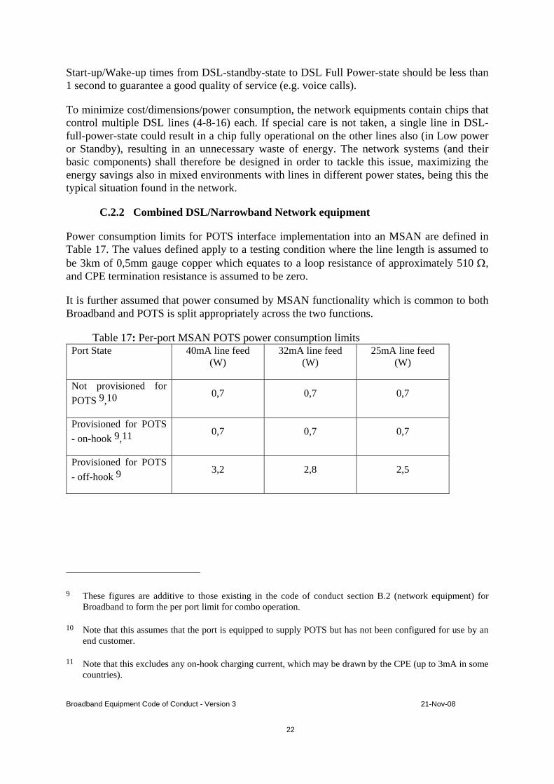
Start-up/Wake-up times from DSL-standby-state to DSL Full Power-state should be less than 1 second to guarantee a good quality of service (e.g. voice calls).
To minimize cost/dimensions/power consumption, the network equipments contain chips that control multiple DSL lines (4-8-16) each. If special care is not taken, a single line in DSL-full-power-state could result in a chip fully operational on the other lines also (in Low power or Standby), resulting in an unnecessary waste of energy. The network systems (and their basic components) shall therefore be designed in order to tackle this issue, maximizing the energy savings also in mixed environments with lines in different power states, being this the typical situation found in the network.
C.2.2 Combined DSL/Narrowband Network equipment
Power consumption limits for POTS interface implementation into an MSAN are defined in Table 17. The values defined apply to a testing condition where the line length is assumed to be 3km of 0,5mm gauge copper which equates to a loop resistance of approximately 510 Ω, and CPE termination resistance is assumed to be zero.
It is further assumed that power consumed by MSAN functionality which is common to both Broadband and POTS is split appropriately across the two functions.
Table 17: Per-port MSAN POTS power consumption limits Port State 40mA line feed
(W) 32mA line feed
(W) 25mA line feed
(W)
Not provisioned for POTS 9,10
0,7 0,7 0,7
Provisioned for POTS - on-hook 9,11
0,7 0,7 0,7
Provisioned for POTS - off-hook 9
3,2 2,8 2,5
9 These figures are additive to those existing in the code of conduct section B.2 (network equipment) for Broadband to form the per port limit for combo operation.
10 Note that this assumes that the port is equipped to supply POTS but has not been configured for use by an end customer.
11 Note that this excludes any on-hook charging current, which may be drawn by the CPE (up to 3mA in some countries).

Broadband Equipment Code of Conduct - Version 3 21-Nov-08
23
C.2.3 Optical Line Terminations (OLT) for PON- and PtP-networks
Table 18: Optical Line Terminations Equipment Tier 2009 (01.01.09)
(W) Tier 2010 (01.01.2010)
(W) Tier 2011 (01.01.2011)
(W)
OLT (GPON, fully equipped with maximum configuration implementing standard Layer-2 (Ethernet) aggregation functionalities, including Multicast)
18 15 11
OLT (GPON, fully equipped with maximum configuration implementing also functionalities at the IP layer such as routing, MPLS, IP QoS)
20 16,5 12
OLT (Point to Point up to 1000Mbit/s, up to 100 ports, fully equipped with maximum configuration)
5 5 TBD
OLT (Point to Point up to 1000Mbit/s, from 100 and 300 ports, fully equipped with maximum configuration)
4 4 TBD
OLT (Point to Point up to 1000Mbit/s, with more than 300 ports, fully equipped with maximum configuration)
3 3 TBD
OLT (Point to Point at 10Gbit/s, up to 12 ports, fully equipped with maximum configuration)
38 38 TBD
OLT (Point to Point at 10Gbit/s, from 12 to 42 ports, fully equipped with maximum configuration)
28 28 TBD
OLT (Point to Point at 10Gbit/s, with more than 42 ports, fully equipped with
18 18 TBD

Broadband Equipment Code of Conduct - Version 3 21-Nov-08
24
maximum configuration)
The above values are for fully equipped with maximum configuration OLTs. The additional allowance for the uplink interface is:
• 4,5W per equipment for each Point to Point 1000Mbit/s interface • 18W per equipment for each Point to Point 10Gbit/s interface • 6W per equipment for each Point to Multipoint (GPON) interface
The above consumption for GPON OLT is per port and with ClassB+ (ITU-T G.984.2 amd1) optical modules whatever the number of ONU connected to it is. The above consumption for point to point OLT is per user port. The optical budget for the OLT P2P interfaces shall be in line with IEEE802.3 clause 58 for the 100Base-LX10 and 100Base-BX10 interfaces and IEEE802.3 clause 59 for the 1000Base-LX10 and 1000Base-BX10 interfaces. A 5 dB channel insertion loss shall be used The Pt-Pt 10Gbit/s limits are applicable only to Point to Point at 10Gbit/s, fully equipped with maximum configuration that directly connect to Customer Premises Equipment associated with broadband distribution for residential customers and SOHO.
C.2.4 Wireless Broadband network equipment
Table 19: Wireless Broadband network equipment Equipment Tier 2009 (01.01.09)
(W) Tier 2010 (01.01.2010)
(W) Tier 2011 (01.01.2011)
(W)
Wi-Fi access points (Hotspot application) 802.11b/g/n or 802.11/b/g/a – ON state and Active Standby12
13 TBD TBD
Wimax Macro Radio Base Station (3 sectors) – ON state TBD TBD TBD
Wimax Micro Radio Base Station (1 sector)– ON state TBD TBD TBD
12 The On-state is defined with no traffic on the Wi-Fi port. Therefore there is no difference in power consumption between the On-state and the Low-power-state (Active Standby) for this equipment.
Broadband Equipment Code of Conduct - Version 3 21-Nov-08
25
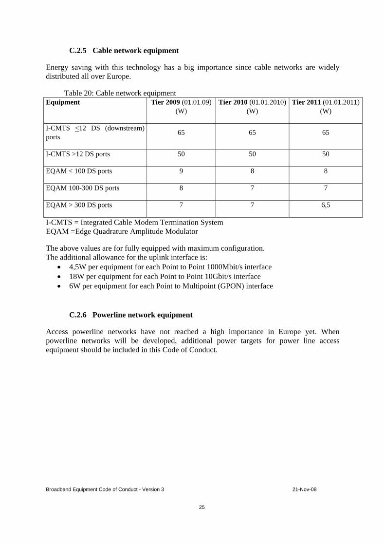
C.2.5 Cable network equipment
Energy saving with this technology has a big importance since cable networks are widely distributed all over Europe.
Table 20: Cable network equipment Equipment Tier 2009 (01.01.09)
(W) Tier 2010 (01.01.2010)
(W) Tier 2011 (01.01.2011)
(W)
I-CMTS <12 DS (downstream) ports 65 65 65
I-CMTS >12 DS ports 50 50 50
EQAM < 100 DS ports 9 8 8
EQAM 100-300 DS ports 8 7 7
EQAM > 300 DS ports 7 7 6,5
I-CMTS = Integrated Cable Modem Termination System EQAM =Edge Quadrature Amplitude Modulator
The above values are for fully equipped with maximum configuration. The additional allowance for the uplink interface is:
• 4,5W per equipment for each Point to Point 1000Mbit/s interface • 18W per equipment for each Point to Point 10Gbit/s interface • 6W per equipment for each Point to Multipoint (GPON) interface
C.2.6 Powerline network equipment
Access powerline networks have not reached a high importance in Europe yet. When powerline networks will be developed, additional power targets for power line access equipment should be included in this Code of Conduct.

Broadband Equipment Code of Conduct - Version 3 21-Nov-08
26
Annex D – Reporting Form
See Reporting Sheet on the homepage of the EU Standby Initiative [3].
Annex E – Test methods
Customer premises equipment
Customer premises equipment with an external power supply shall be measured 230V AC input in all states (when existing) as they are described in Annex B.1. In the future, standardization bodies like ETSI could provide a more detailed specification for the measurement of the power consumption in different states.
Network equipment
The values given in Annex C.2 are indicating the averaged power consumption per port for a fully equipped system as delivered by the manufacturer. Systems powered by DC Voltage shall comply with the standard ETSI ETS 300 132-2 "Environmental Engineering (EE); Power supply interface at the input to telecommunications equipment; Part 2: Operated by direct current (dc)” [7]. The method of power measurement shall comply with the Technical Specification ETSI TS 102 533 "Environmental Engineering (EE); Measurement Methods and limits for Energy Consumption in Broadband Telecommunication Networks Equipment" [8]. In case of systems powered directly by AC mains voltage, the power consumption will have to be measured at the AC input. For such systems, the power limits stated in Table 14 through Table 20, may be increased by 10%. The power limits have to be fulfilled for the system operating in the complete operational temperature range of the system itself.

Broadband Equipment Code of Conduct - Version 3 21-Nov-08
27
Annex F – List of abbreviations
ADSL Asymmetric Digital Subscriber Line ADSL2+ Second generation ADSL with extended bandwidth ATA Analogue Terminal Adapter CoC Code of Conduct COP Coefficient Of Performance CPE Customer Premises Equipment DECT Digital Enhanced Cordless Telecommunications DOCSIS Data Over Cable Service Interface Specification DSL Digital Subscriber Line DSLAM Digital Subscriber Line Access Multiplexer ETSI European Telecommunications Standards Institute FXO Foreign eXchange Office FXS Foreign eXchange Station GPON Gigabit Passive Optical Network HPNA Home PNA Alliance IEEE Institute of Electrical and Electronics Engineers IP Internet Protocol ITU International Telecommunication Union LAN Local Area Network LT Line Termination MoCA Multimedia over Coax Alliance MSAN Multi Service Access Node NAT Network Address Translation NT Network Termination ONT Optical Network Termination PtP Point-to-Point Optical Network PLC PowerLine Communication PoE Power over Ethernet PON Passive Optical Network POTS Plain Old Telephone Service SOHO Small Office, Home Office USB Universal Serial Bus VDSL2 Very High Speed Digital Subscriber Line 2nd generation VoIP Voice over IP WAN Wide Area Network Wi-Fi Wireless Fidelity; technology using 802.11 standards
Broadband Equipment Code of Conduct - Version 3 21-Nov-08
28
Annex G – List of references
[1] ITU-T recommendation I.113 Vocabulary of terms for broadband aspects of ISDN
[2] Code of Conduct for Digital TV Services (version 7 – 15 January 2008) , http://re.jrc.ec.europa.eu/energyefficiency/html/standby_initiative.htm
[3] Reporting sheet CoC BB equipment http://re.jrc.ec.europa.eu/energyefficiency/html/standby_initiative_broadband%20communication.htm
[4] EU Code of Conduct for External Power Supplies Version 3 of 28.11.2008, http://re.jrc.ec.europa.eu/energyefficiency/html/standby_initiative_External%20Power%20Supplies.htm
[5] ETSI Standard EN 300019-1-3 European Standard, Environmental Engineering (EE); Environmental conditions and environmental tests for telecommunications equipment; Part 1-3: Classification of environmental conditions; Stationary use at weather protected locations
[6] EU Code of Conduct on Energy Efficiency of Broadband Equipment Version 2 of July 17th 2007
[7] ETSI ETS 300 132-2 European Standard, Equipment Engineering (EE); Power supply interface at the input to telecommunications equipment; Part 2: Operated by direct current (dc)
[8] ETSI TS 102 533, Technical Specification, Environmental Engineering (EE), Measurement Methods and limits for Energy Consumption in Broadband Telecommunication Networks Equipment

Broadband Equipment Code of Conduct – Version 3 18 November 2008
Code of Conduct On Energy Consumption of Broadband Equipment
SIGNING FORM
The organisation/company/
………………………………………………………………..
signs the Code of Conduct on Energy Consumption of Broadband Equipment and commits itself to abide to the principles described in point 3 “Commitment” for the equipment it produces, buys, installs or specifies. The organisation, through regular upgrade reports, will keep the European Commission informed on the implementation of the Code of Conduct of Broadband Equipment.
for the organisation Director or person authorised to sign: Name: ……………………………… . . . . . . . . . . . Managerial Function: ………………………………. . . . . . . . . . . Address ……………………………………………… Tel. / Fax. ………………………/ …………….……… Email: ………………………………………………. Date: ………………………………………………. Signature …………………………………. Please send the signed form to: Paolo Bertoldi European Commission - DG JRC TP 450 I-21020 Ispra (VA) tel. +39 0332 78 9299 (secretary 9145) fax. +39 0332 78 9992
E-mail: [email protected]