coating flexible probes with an ultra fast degrading ...rci.rutgers.edu/~shreiber/bmmdprobe.pdf ·...
TRANSCRIPT
Coating flexible probes with an ultra fast degrading polymerto aid in tissue insertion
Meng-chen Lo & Shuwu Wang & Sagar Singh &
Vinod B. Damodaran & Hilton M. Kaplan &
Joachim Kohn & David I. Shreiber & Jeffrey D. Zahn
# Springer Science+Business Media New York 2015
Abstract We report a fabrication process for coating neuralprobes with an ultrafast degrading polymer to create consis-tent and reproducible devices for neural tissue insertion. Therigid polymer coating acts as a probe insertion aid, but resorbswithin hours post-implantation. Despite the feasibility forshort term neural recordings from currently available neuralprosthetic devices, most of these devices suffer from long termgliosis, which isolates the probes from adjacent neurons, in-creasing the recording impedance and stimulation threshold.The size and stiffness of implanted probes have been identi-fied as critical factors that lead to this long term gliosis.Smaller, more flexible probes that match the mechanical prop-erties of brain tissue could allow better long term integrationby limiting the mechanical disruption of the surrounding tis-sue during and after probe insertion, while being flexibleenough to deform with the tissue during brain movement.However, these small flexible probes inherently lack the me-chanical strength to penetrate the brain on their own. In thiswork, we have developed a micromolding method for coatinga non-functional miniaturized SU-8 probe with an ultrafastdegrading tyrosine-derived polycarbonate (E5005(2K)).Coated, non-functionalized probes of varying dimensionswere reproducibly fabricated with high yields. The polymererosion/degradation profiles of the probes were characterizedin vitro. The probes were also mechanically characterized inex vivo brain tissue models by measuring buckling and inser-tion forces during probe insertion. The results demonstrate theability to produce polymer coated probes of consistent quality
for future in vivo use, for example to study the effects ofdifferent design parameters that may affect tissue responseduring long term chronic intra-cortical microelectrode neuralrecordings.
Keywords Microfabrication . Neural probe . Flexible probe .
Biodegradable polymer
1 Introduction
Brain computer interfaces (BCI) establish communication be-tween the brain and external devices without transmissionthrough peripheral neural pathways (Daly and Wolpaw2008; Hochberg et al. 2006, 2012). There is rising interestand need for BCIs to assist people who have suffered fromnervous system impairments (e.g., spinal cord injury, demye-lination diseases, neurodegenerative diseases). The first stepin this process is signal recording. It is, therefore, essential todevelop suitable recording modalities that are capable ofobtaining high quality, consistent signals, while facilitatinglong-term probe implantation to enable lifetime use of BCIdevices. There has been extensive research on neural probedevelopment, covering many different design aspects such asprobe materials, probe dimensions, microfabrication process-es, electrode dimensions and the electrode-cell interface (Luet al. 2010; Ming et al. 2002; Pfurtscheller et al. 2000;Rousche and Normann 1998; Sun et al. 2014; Vaughan et al.2003).
Pioneering neural recording studies usedminiaturized 30 to50 μm diameter metal wires made from platinum, iridium,copper or stainless steel and coupled with a Teflon or polyim-ide coating as insulation (Salcman and Bak 1973; Schmidtet al. 1976). Development of microfabrication techniques en-hanced the capabilities of neural recording devices. Siliconmicrofabrication processes provide fine control over the probe
M.<c. Lo (*) : S. Singh :D. I. Shreiber : J. D. ZahnDepartment of Biomedical Engineering, Rutgers, the StateUniversity of New Jersey, Piscataway, NJ, USAe-mail: [email protected]
S. Wang :V. B. Damodaran :H. M. Kaplan : J. KohnNew Jersey Center for Biomaterials, Rutgers, the StateUniversity of New Jersey, Piscataway, NJ, USA
Biomed Microdevices (2015) 17:34 DOI 10.1007/s10544-015-9927-z
and electrode size, shape, spacing and even allow multiplerecording sites to be fabricated within each probe to increasethe device efficacy (Wise et al. 1970). Despite the feasibilityfor short term neural recordings (~2–6 weeks) (Rousche andNormann 1998; Williams et al. 1999) from these differenttypes of probes, most of the devices ultimately failed due todisruption of the electrode-cell interface by the foreign bodyresponse, which alters the recording feasibility over time untilthe probes are finally no longer able to acquire stable andconsistent signals (Edell et al. 1992; Kozai et al. 2012b;Lund et al. 2010; Polikov et al. 2005; Turner et al. 1999;Vetter et al. 2004; Wang and Thampatty 2008).
Two forms of tissue response cause this mode of failure: (1)acute activation of microglia and astrocytes (Polikov et al.2005; Turner et al. 1999); (2) chronic glial scar formation(Biran et al. 2005; Szarowski et al. 2003).When neural probesare inserted into brain tissue, the mechanical trauma causescellular damage and disruption of blood vessels which leadsto astrocyte and microglia activation (Bjornsson et al. 2006;Fujita et al. 1998; Giordana et al. 1994), which interfere withmicrocirculation. Disruption of blood vessels releases eryth-rocytes, clotting factors, and inflammatory factors that facili-tate macrophage recruitment and alter the probe’s recordingperformance (Saxena et al. 2013; Turner et al. 1999). Thisacute inflammatory response usually subsides within 1 weekpost probe insertion (Fujita et al. 1998; Leskovar et al. 2000).
However, a chronic foreign body response can then beobserved, presumably aggravated by continual shear forcesof the brain moving relative to the rigid probes (Seymourand Kipke 2007; Szarowski et al. 2003). Most functionalprobe failures result from this long term CNS response, inwhich gliosis forms an encapsulation layer that isolates theelectrodes from the adjacent neural cells (Edell et al. 1992;Rousche and Normann 1998; Szarowski et al. 2003; Turneret al. 1999). This encapsulation electrically insulates theprobes, which impairs the devices by dramatically increasingtheir recording impedance (Mercanzini et al. 2009; Williamset al. 2007), and so decreasing the signal to noise ratio (SNR)(Edell et al. 1992; Vetter et al. 2004).
Larger devices (>100 μm wide long-term) are expected tocause more tissue disruption, chronic shear injury, anda foreign body response, and ultimately induce a more severechronic glial encapsulation (Kipke et al. 2008; Kozai et al.2012a; Seymour and Kipke 2007). It is hypothesized that cre-ating miniaturized probes will help reduce the extent of bothacute and chronic tissue response through minimizing inser-tion trauma (Ebersole 1997; Subbaroyan and Kipke 2006;Takeuchi et al. 2003). In the late 1990’s, several groups sug-gested the fabrication of flexible probes from polymer mate-rials to minimize tissue responses by aiming to mechanicallymatch device compliance with that of adjacent tissues(Hoogerwerf and Wise 1994; Stieglitz et al. 1997; Takeuchiand Shimoyama 2000). Since then, more flexible materials
have been used, including SU-8, polyimide or poly(p-xylylene) (parylene) to replace or improve recording abilitycompared to rigid silicon-based probes (Altuna et al. 2012;Cho et al. 2008; González and Rodríguez 1997; Smith et al.2012). However, effective insertion of these flexible probesusually requires probes larger than their silicon counterpartsand/or large insertion shuttles to aid in implantation.
Various insertion aids have been investigated to allow in-sertion of flexible probes. An ideal insertion aid will providesufficient mechanical strength to penetrate the tissue in a nar-row and sharp form factor to minimize the tissue responseinduced by insertion. Insertion aids made from stiffer mate-rials such as needles or silicon shanks have been incorporatedwith the flexible probes as temporary insertion shuttles and areremoved after implantation (Felix et al. 2013; Kim et al.2013). However, those types of removable shuttles are usuallystiffer and larger in size, and may therefore compromise short-term probe performance due to mechanical trauma.
One other method to stiffen flexible microprobes is to en-capsulate the device within biodegradable polymers for inser-tion. Poly(ethylene glycol) (PEG) has been investigated as aninsertion aid due to its biocompatibility and solubility in thetissue body fluids (Chen et al. 2009, 2011; Takeuchi et al.2005); however PEG has limited rigidity and therefore re-quires thicker coatings or a shuttle to ensure successful inser-tion. Poly(D,L-lactide-co-glycolide) (PLGA) has also beenused as an insertion aid for flexible parylene neural probesbecause it is both biocompatible and biodegradable and iswidely used in biomedical applications (Foley et al. 2009).However, the degradation time of PLGA is around 3 to 4weeks,which exceeds the time over which the acute and even chronictissue responses occur. Carboxyl-methylcellulose (CMC) hasalso been proposed as a shuttle which can couple with neuralprobes for insertion (Gilgunn et al. 2012). It is bio-dissolvableand has also been proposed as a matrix for slow release of othermolecules such as neural regenerative drugs to prevent tissueresponses. However, when tested, the CMC composite wasreported to become gel-like instead of completely degradingwithin the body, thereby potentially limiting the proximity ofneural units.
More recently, there are groups fabricating probes usingnovel materials where the stiffness is reduced following de-vice implantation. One example is the fabrication of devicesout of shape memory polymers that are stiff during implanta-tion and soften in vivo to approach the brain tissue modulus(Ware et al. 2012). However, the device stiffness (shear mod-ulus ~700 MPa) prior to insertion is still less than silicon(~200 GPa) and therefore a larger device is required to ensuresuccessful implantation. A mechanically adaptive polymernanocomposite probe has been fabricated via film casting(Harris et al. 2011; Nguyen et al. 2014). The material is capa-ble of decreasing its tensile modulus from 5 GPa pre-insertionto 12 MPa post-insertion within 15 minutes under
34 Page 2 of 11 Biomed Microdevices (2015) 17:34
physiological conditions. However, since the study examinedthe implants without electrode traces, future investigation maybe needed to ensure that the nanocomposite casting procedurecan accommodate the patterning of recording elements.
In this work, we have developed a micromolding methodfor coating a non-functional miniaturized SU-8 probe with anultrafast degrading tyrosine-derived polycarbonate(E5005(2K)). The polymer is both biocompatible and biode-gradable, and degrades into non-toxic, resorbable tyrosine andPEG by-products that have no harmful effects (Bourke andKohn 2003; Hooper et al. 1998). Furthermore, the degradationrate of the polymer is easily tunable by variations in the poly-mer composition (Ertel and Kohn 1994; Hooper et al. 1998).This polymer is stiffer than PEG on its own, and providessufficient strength for device implantation followed by anultra-fast (~1–2 h) degradation and resorption that leaves onlythe microprobe inserted within the tissue (Lewitus et al. 2011).Previous work by our group (Lewitus et al. 2011) used a dipcoating to coat the probe. The coating dimensions were lessdefined and usually thicker than what is required for insertion.For this study, we designed a proof-of-concept fabricationprocess adapting the water and temperature sensitive charac-teristics of the polymer to produce devices with more definedprobe and coating dimensions. Specifically, SU-8 probes withdifferent probe and coating dimensions were fabricated.The polymer coated probes were chemically characterizedto investigate the coating polymer resorption profile andverify that the probe remained intact after the polymerdegraded. The probes were also mechanically examinedfor buckling force to evaluate the probe integrity. We ex-pect this coating procedure can be further utilized to coatprobes of varying dimensions fabricated from a variety ofdifferent materials such as SU-8, parylene or polyimide.
2 Materials and methods
2.1 Polymer preparation
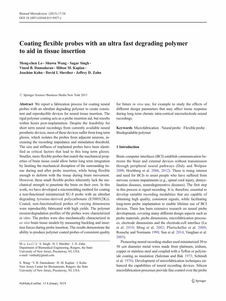
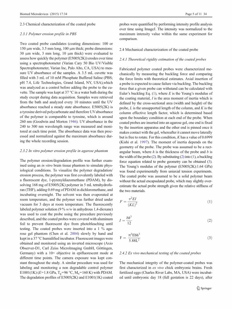
The tyrosine-derived polycarbonate based co-polymerused for coating was synthesized at the New JerseyCenter for Biomaterials according to previously publishedprocedures (Rojas et al. 2009; Schut et al. 2007) from 3mono-mers: desaminotyrosyl-tyrosine alkyl ethyl ester (DTE),desaminotyrosyl-tyrosine (DT), and low-molecular-weightpoly(ethylene glycol) (PEG). The naming convention for thistype of polymer is EXXYY(MW), meaning poly(DTE-co-XX%DT-co-YY%-PEGMW carbonate) where XX is themole percent of DT, YY is the mole percent of the PEG andthe MW is the average molecular weight of the PEG (Fig. 1).The mechanical and chemical properties of these polymersdepend on the polymer composition and relative molar per-centages of the three monomers. The DTE component
provides strength and stability, the DT component determinesresorption rate and has a carboxyl group that allows function-ality, and the PEG component determines resorbtion rate. Thepolymer degrades via hydrolysis of the carbonate linkages.The incorporation of DT and PEG in the polymer backbonemakes the polymer more hydrophilic, enhancing the degra-dation rate by allowing faster water absorption. The specifictype of polymer that was primarily used is E5005(2K) (E=1.6 GPa, Tg=57 °C, Mn=100 K) which is 50 % DT, 5 %PEG. The E5005(2K) composition was found to have theproper mechanical and chemical qualities desired for aninsertion aid, in that it has a fairly high Young’s modulus(E=1.6 GPa), while being able to chemically degrade fullywithin a few hours (Lewitus et al. 2011).
2.2 SU-8 non-functional probe fabrication and polymercoating procedure
2.2.1 Polymer coated SU-8 probe fabrication
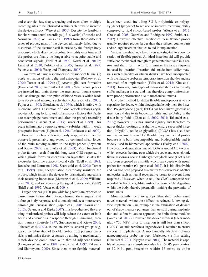
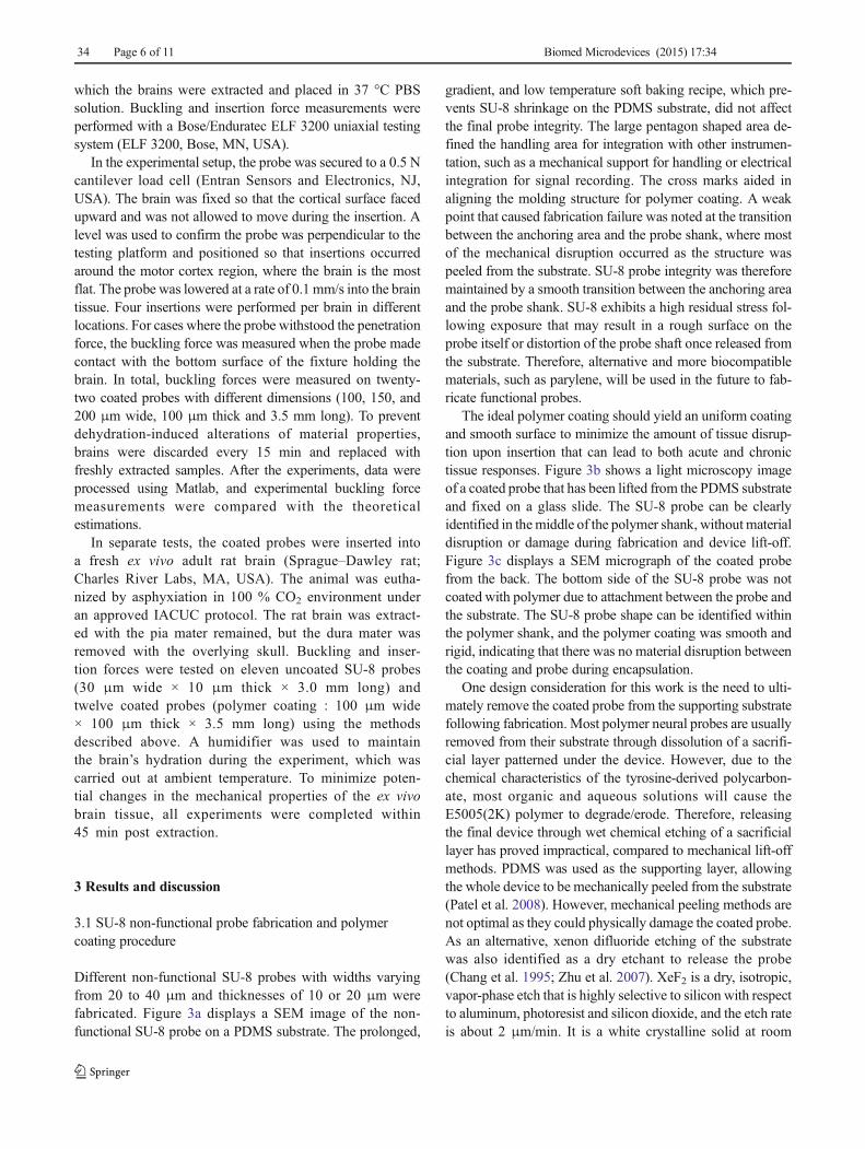
SU-8 was chosen as a test material on which to develop thecoating procedure. The microprobe fabrication can be splitinto two parts: 1) Polymer coating mold fabrication; 2)Probe fabrication and polymer coating. The polymer coatingmold was fabricated via a standard photolithography process.A thick negative photoresist (SU-8 2075) was spin-coated(1000 rpm) on a silicon substrate to the desired thickness(100 μm). The molding structure was defined and patternedby photolithography. Polydimethylsiloxane (PDMS) waspoured over the master to create the molding cavity throughsoft lithography. After curing, the PDMS molding structurewas removed from the wafer and a hole was drilled throughthe anchoring area as a solution inlet for use in the down-stream polymer coating process.
PDMSwas chosen as a substrate layer for probe fabricationto take advantage of the weak adhesion between PDMS andSU-8. This allowed for the SU-8 device to be lifted from thesubstrate while still providing support to carry out photoli-thography to define the probe structure. To prevent significantcontraction of SU-8 layer during baking because of rapid sol-vent evaporation, a special soft baking recipe at a lower tem-perature for a longer baking time was conducted. This ensuredthe desired uniform coating of SU-8 on top of the PDMSsubstrate (Fig. 2). First, PDMS was mixed with the curingagent at 10:1 weight ratio for substrate coating. A thin layerof PDMS (65 μm) was spin-coated (2000 rpm) on top of theglass substrate, and baked for 5 min to cure the PDMS.Second, a thin layer of SU-8 (SU-8 2010; 10–20 μm thick)was spin-coated on top of the cured PDMS substrate layer.The whole device was then baked at 30, 35, 40, 45, 50, 55,60 and 65 °C for 5 minutes at each temperature, and thencooled to room temperature for at least 1 hour before down-stream exposure. The SU-8 was then patterned to the probe
Biomed Microdevices (2015) 17:34 Page 3 of 11 34
geometries with standard photolithography. The probe wasimaged using scanning electron microscope (SEM)(AMRAY-1830I, AMRAY, Bedford, MA, USA) to ensureprobe integrity prior to polymer coating. Following probe def-inition, the PDMS molding piece, previously fabricated, wasaligned with the SU-8 probe under a light microscope, andpressed onto the substrate to form a conformal contact and amolding capillary.
The E5005(2K) polymer solution was infused from themolding inlet to coat the probe using the micromolding incapillaries (MIMIC) (Kim et al. 1996) process, where polymersolution is introduced into a microchannel reservoir and fillsthe cavities through capillary action. The E5005(2K) polymersolution was prepared as 9 % w/w in anhydrous 1, 4-dioxane(Sigma-Aldrich, St. Louis, MO, USA). To start the coatingprocess, 5 μL of polymer solution was introduced throughthe reservoir inlet twice at room temperature. The whole
device was then placed on a 75 °C hotplate, and 5 μL of thepolymer solution was introduced 3 times at 5 minutes inter-vals. The device remained on the hotplate for another 2 hoursto drive off the solvent. To slowly and completely evaporatethe solvent within the polymer, the whole device was placedunder −15 mmHg vacuum at 50 °C for an hour, and finally infull vacuum (−30 mmHg) for at least 1 day. The vacuum wasincreased slowly to remove any air bubbles and prevent cav-itation of the solvent and improve the coating quality. Finally,the PDMS molding structure was peeled off from the PDMSsubstrate and physically lifted away using tweezers. The coat-ed probes were then stored in 24-well cell plates that werevacuum sealed and stored in a −20 °C freezer until down-stream characterization to prevent polymer degradation fromambient humidity. For testing, probes were returned to roomtemperature under vacuum for 15 minutes and fixed on a glassslide.
Desaminotyrosyl-tyrosineester
(DTE)
Desaminotyrosyl-tyrosine
(DT)
Poly(ethylene glycol)
(PEG)
Fig. 1 Chemical structure of thetyrosine-derived polycarbonate(Poly (DTE-co-XX%DT-co-YY%PEG(Wk)))
Fig. 2 Schematic of polymercoating fabrication process. a thinlayer of PDMS (~65 μm) is spincoated on to a substrate. b Theprobe geometry is patterned ontop of the PDMS layer. c The SU-8 probe is aligned with the mold-ing structure. d Polymer solutionis infused through the inlet of themold usingMIMIC technique andthe polymer solvent is allowed toevaporate.e The device is released from thesubstrate. f The device is releasedfrom the molding structure. g Thedevice is lifted mechanically offfrom the PDMS substrate
34 Page 4 of 11 Biomed Microdevices (2015) 17:34
2.3 Chemical characterization of the coated probe
2.3.1 Polymer erosion profile in PBS
Two coated probe candidates (coating dimensions: 100 or150 μmwide, 3.5 mm long, 100 μm thick; probe dimensions:30 μm wide, 3 mm long, 10 μm thick) were evaluated toassess how quickly the polymer (E5005(2K)) erodes over timeusing a spectrophotometer (Varian Cary 50 Bio UV/VisibleSpectrophotometer, Varian Inc, Palo Alto, CA, USA) to mea-sure UV absorbance of the samples. A 3.5 mL cuvette wasfilled with 3 mL of 10 mM Phosphate Buffered Saline (PBS;pH 7.4, Life Technologies, Grand Island, NY, USA),whichwas analyzed as a control before adding the probe to the cu-vette. The sample was kept at 37 °C in a water bath during thestudy except during data acquisition. Samples were retrievedfrom the bath and analyzed every 10 minutes until the UVabsorbance reached a steady state absorbance. E5005(2K) isa tyrosine derived polycarbonate and therefore UVabsorbanceof the polymer is comparable to tyrosine, which is around260 nm (Goodwin and Morton 1946). UV absorbance in the240 to 300 nm wavelength range was measured and moni-tored at each time point. The absorbance data was then proc-essed and normalized against the maximum absorbance dur-ing the whole recording session.
2.3.2 In vitro polymer erosion profile in agarose phantom
The polymer erosion/degradation profile was further exam-ined using an in vitro brain tissue phantom to simulate phys-iological conditions. To visualize the polymer degradation/erosion process, the polymer was first covalently labeled witha fluorescent dye, 1-pyrenyldiazomethane (PDAM), by dis-solving 168 mg of E5005(2K) polymer in 5 mL tetrahydrofu-ran (THF), adding 0.69mg of PDAM in dichloromethane, andincubating overnight. The solvent was then evaporated atroom temperature, and the polymer was further dried undervacuum for 3 days at room temperature. The fluorescentlylabeled polymer solution (9 % w/w in anhydrous 1,4-dioxane)was used to coat the probe using the procedure previouslydescribed, and the coated probes were covered with aluminumfoil to prevent fluorescent dye from photobleaching untiltesting. The coated probes were inserted into a 1 % aga-rose gel phantom (Chen et al. 2004) slowly by hand andkept in a 37 °C humidified incubator. Fluorescent images wereobtained and monitored using an inverted microscope (AxioObserver-D1, Carl Zeiss MicroImaging GmbH, Göttingen,Germany) with a 10× objective in epifluorescent mode atdifferent time points. The camera exposure was kept con-stant throughout the study. A similar procedure was used forlabeling and monitoring a non degradable control polymerE1001(1K) (E=1.8 GPa, Tg=96 °C, Mn=160 K) with PDAM.The degradation profiles of E5005(2K) and E1001(1K) coated
probes were quantified by performing intensity profile analysisover time using ImageJ. The intensity was normalized to themaximum intensity value within the same experiment forcomparison.
2.4 Mechanical characterization of the coated probe
2.4.1 Theoretical rigidity estimation of the coated probes
Fabricated polymer coated probes were characterized me-chanically by measuring the buckling force and comparingthe force limits with theoretical estimates. Axial insertion ofa probe is expected to cause failure via buckling. The bucklingforce that a given probe can withstand can be calculated withEuler’s buckling Eq. (1), where E is the Young’s modulus ofthe coating material, I is the area moment of inertia which isdefined by the cross-sectional area (width and height) of theprobe, L is the unsupported length of the column, and K is thecolumn effective length factor, which is determined basedupon the boundary condition at each end of the probe. Whencoated probes are inserted into an agarose gel, one end is fixedby the insertion apparatus and the other end is pinned once itmakes contact with the gel, whereafter it cannot move laterallybut is free to rotate. For this condition,K has a value of 0.6999(Kishi et al. 1997). The moment of inertia depends on thegeometry of the probe. The probe was assumed to be a rect-angular beam, where h is the thickness of the probe and b isthewidth of the probe (2). By substituting (2) into (1), a bucklingforce equation related to probe geometry can be obtained (3).The Young’s modulus of the polymer (E5005(2K):1.64 GPa)was found experimentally from uniaxial tension experiments.The coated probe was assumed to be a solid polymer beamwithout the actual encapsulated probe, which may slightly over-estimate the actual probe strength given the relative stiffness ofthe two materials.
F ¼ π2EI
KLð Þ2 ð1Þ
I ¼ bh3
12ð2Þ
F ¼ π2Ebh3
5:88L2 ð3Þ
2.4.2 Ex vivo mechanical testing of the coated probes
The mechanical integrity of the polymer-coated probes wasfirst characterized in ex vivo chick embryonic brains. Freshfertilized eggs (Charles River Labs, MA, USA) were incubat-ed until embryonic day 18 (full gestation is 22 days), after
Biomed Microdevices (2015) 17:34 Page 5 of 11 34
which the brains were extracted and placed in 37 °C PBSsolution. Buckling and insertion force measurements wereperformed with a Bose/Enduratec ELF 3200 uniaxial testingsystem (ELF 3200, Bose, MN, USA).
In the experimental setup, the probe was secured to a 0.5 Ncantilever load cell (Entran Sensors and Electronics, NJ,USA). The brain was fixed so that the cortical surface facedupward and was not allowed to move during the insertion. Alevel was used to confirm the probe was perpendicular to thetesting platform and positioned so that insertions occurredaround the motor cortex region, where the brain is the mostflat. The probe was lowered at a rate of 0.1 mm/s into the braintissue. Four insertions were performed per brain in differentlocations. For cases where the probe withstood the penetrationforce, the buckling force was measured when the probe madecontact with the bottom surface of the fixture holding thebrain. In total, buckling forces were measured on twenty-two coated probes with different dimensions (100, 150, and200 μm wide, 100 μm thick and 3.5 mm long). To preventdehydration-induced alterations of material properties,brains were discarded every 15 min and replaced withfreshly extracted samples. After the experiments, data wereprocessed using Matlab, and experimental buckling forcemeasurements were compared with the theoreticalestimations.
In separate tests, the coated probes were inserted intoa fresh ex vivo adult rat brain (Sprague–Dawley rat;Charles River Labs, MA, USA). The animal was eutha-nized by asphyxiation in 100 % CO2 environment underan approved IACUC protocol. The rat brain was extract-ed with the pia mater remained, but the dura mater wasremoved with the overlying skull. Buckling and inser-tion forces were tested on eleven uncoated SU-8 probes(30 μm wide × 10 μm thick × 3.0 mm long) andtwelve coated probes (polymer coating : 100 μm wide× 100 μm thick × 3.5 mm long) using the methodsdescribed above. A humidifier was used to maintainthe brain’s hydration during the experiment, which wascarried out at ambient temperature. To minimize poten-tial changes in the mechanical properties of the ex vivobrain tissue, all experiments were completed within45 min post extraction.
3 Results and discussion
3.1 SU-8 non-functional probe fabrication and polymercoating procedure
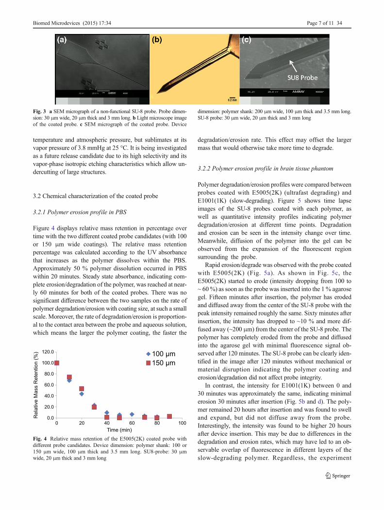
Different non-functional SU-8 probes with widths varyingfrom 20 to 40 μm and thicknesses of 10 or 20 μm werefabricated. Figure 3a displays a SEM image of the non-functional SU-8 probe on a PDMS substrate. The prolonged,
gradient, and low temperature soft baking recipe, which pre-vents SU-8 shrinkage on the PDMS substrate, did not affectthe final probe integrity. The large pentagon shaped area de-fined the handling area for integration with other instrumen-tation, such as a mechanical support for handling or electricalintegration for signal recording. The cross marks aided inaligning the molding structure for polymer coating. A weakpoint that caused fabrication failure was noted at the transitionbetween the anchoring area and the probe shank, where mostof the mechanical disruption occurred as the structure waspeeled from the substrate. SU-8 probe integrity was thereforemaintained by a smooth transition between the anchoring areaand the probe shank. SU-8 exhibits a high residual stress fol-lowing exposure that may result in a rough surface on theprobe itself or distortion of the probe shaft once released fromthe substrate. Therefore, alternative and more biocompatiblematerials, such as parylene, will be used in the future to fab-ricate functional probes.
The ideal polymer coating should yield an uniform coatingand smooth surface to minimize the amount of tissue disrup-tion upon insertion that can lead to both acute and chronictissue responses. Figure 3b shows a light microscopy imageof a coated probe that has been lifted from the PDMS substrateand fixed on a glass slide. The SU-8 probe can be clearlyidentified in themiddle of the polymer shank, without materialdisruption or damage during fabrication and device lift-off.Figure 3c displays a SEM micrograph of the coated probefrom the back. The bottom side of the SU-8 probe was notcoated with polymer due to attachment between the probe andthe substrate. The SU-8 probe shape can be identified withinthe polymer shank, and the polymer coating was smooth andrigid, indicating that there was no material disruption betweenthe coating and probe during encapsulation.
One design consideration for this work is the need to ulti-mately remove the coated probe from the supporting substratefollowing fabrication. Most polymer neural probes are usuallyremoved from their substrate through dissolution of a sacrifi-cial layer patterned under the device. However, due to thechemical characteristics of the tyrosine-derived polycarbon-ate, most organic and aqueous solutions will cause theE5005(2K) polymer to degrade/erode. Therefore, releasingthe final device through wet chemical etching of a sacrificiallayer has proved impractical, compared to mechanical lift-offmethods. PDMS was used as the supporting layer, allowingthe whole device to be mechanically peeled from the substrate(Patel et al. 2008). However, mechanical peeling methods arenot optimal as they could physically damage the coated probe.As an alternative, xenon difluoride etching of the substratewas also identified as a dry etchant to release the probe(Chang et al. 1995; Zhu et al. 2007). XeF2 is a dry, isotropic,vapor-phase etch that is highly selective to silicon with respectto aluminum, photoresist and silicon dioxide, and the etch rateis about 2 μm/min. It is a white crystalline solid at room
34 Page 6 of 11 Biomed Microdevices (2015) 17:34
temperature and atmospheric pressure, but sublimates at itsvapor pressure of 3.8 mmHg at 25 °C. It is being investigatedas a future release candidate due to its high selectivity and itsvapor-phase isotropic etching characteristics which allow un-dercutting of large structures.
3.2 Chemical characterization of the coated probe
3.2.1 Polymer erosion profile in PBS
Figure 4 displays relative mass retention in percentage overtime with the two different coated probe candidates (with 100or 150 μm wide coatings). The relative mass retentionpercentage was calculated according to the UV absorbancethat increases as the polymer dissolves within the PBS.Approximately 50 % polymer dissolution occurred in PBSwithin 20 minutes. Steady state absorbance, indicating com-plete erosion/degradation of the polymer, was reached at near-ly 60 minutes for both of the coated probes. There was nosignificant difference between the two samples on the rate ofpolymer degradation/erosion with coating size, at such a smallscale. Moreover, the rate of degradation/erosion is proportion-al to the contact area between the probe and aqueous solution,which means the larger the polymer coating, the faster the
degradation/erosion rate. This effect may offset the largermass that would otherwise take more time to degrade.
3.2.2 Polymer erosion profile in brain tissue phantom
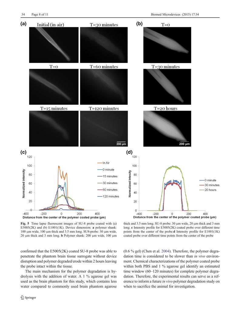
Polymer degradation/erosion profiles were compared betweenprobes coated with E5005(2K) (ultrafast degrading) andE1001(1K) (slow-degrading). Figure 5 shows time lapseimages of the SU-8 probes coated with each polymer, aswell as quantitative intensity profiles indicating polymerdegradation/erosion at different time points. Degradationand erosion can be seen in the intensity change over time.Meanwhile, diffusion of the polymer into the gel can beobserved from the expansion of the fluorescent regionsurrounding the probe.
Rapid erosion/degrade was observed with the probe coatedwith E5005(2K) (Fig. 5a). As shown in Fig. 5c, theE5005(2K) started to erode (intensity dropping from 100 to~ 60%) as soon as the probe was inserted into the 1 % agarosegel. Fifteen minutes after insertion, the polymer has erodedand diffused away from the center of the SU-8 probe with thepeak intensity remained roughly the same. Sixty minutes afterinsertion, the intensity has dropped to ~10 % and more dif-fused away (~200 μm) from the center of the SU-8 probe. Thepolymer has completely eroded from the probe and diffusedinto the agarose gel with minimal fluorescence signal ob-served after 120 minutes. The SU-8 probe can be clearly iden-tified in the image after 120 minutes without mechanical ormaterial disruption indicating the polymer coating anderosion/degradation did not affect probe integrity.
In contrast, the intensity for E1001(1K) between 0 and30 minutes was approximately the same, indicating minimalerosion 30 minutes after insertion (Fig. 5b and d). The poly-mer remained 20 hours after insertion and was found to swelland expand, but did not diffuse away from the probe.Interestingly, the intensity was found to be higher 20 hoursafter device insertion. This may be due to differences in thedegradation and erosion rates, which may have led to an ob-servable overlap of fluorescence in different layers of theslow-degrading polymer. Regardless, the experiment
0.0
20.0
40.0
60.0
80.0
100.0
120.0
0 20 40 60 80 100
Re
lative
Ma
ss R
ete
ntio
n (
%)
Time (min)
Fig. 4 Relative mass retention of the E5005(2K) coated probe withdifferent probe candidates. Device dimension: polymer shank: 100 or150 μm wide, 100 μm thick and 3.5 mm long. SU8-probe: 30 μmwide, 20 μm thick and 3 mm long
Fig. 3 a SEM micrograph of a non-functional SU-8 probe. Probe dimen-sion: 30 μm wide, 20 μm thick and 3 mm long. b Light microscope imageof the coated probe. c SEM micrograph of the coated probe. Device
dimension: polymer shank: 200 μm wide, 100 μm thick and 3.5 mm long.SU-8 probe: 30 μm wide, 20 μm thick and 3 mm long
Biomed Microdevices (2015) 17:34 Page 7 of 11 34
confirmed that the E5005(2K) coated SU-8 probe was able topenetrate the phantom brain tissue surrogate without devicedisruption and polymer degraded/erode within 2 hours leavingthe probe intact within the tissue.
The main mechanism for the polymer degradation is hy-drolysis with the addition of water. A 1 % agarose gel wasused as the brain phantom for this study, which contains lesswater compared to commonly used brain phantom agarose
(0.6 % gel) (Chen et al. 2004). Therefore, the polymer degra-dation time is considered to be slower than in vivo environ-ment. Chemical characterizations of the polymer coated probewithin both PBS and 1 % agarose gel identify an estimatedtime window (60–120 minutes) for complete polymer degra-dation. Therefore, the experimental results can serve as a ref-erence to inform a future in vivo polymer degradation study onwhen to sacrifice the animal for investigation.
Fig. 5 Time lapse fluorescent images of SU-8 probe coated with (a)E5005(2K) and (b) E1001(1K). Device dimension: a polymer shank:100 μm wide, 100 μm thick and 3.5 mm long. SU8-probe: 30 μm wide,20 μm thick and 3 mm long. b Polymer shank: 200 μm wide, 100 μm
thick and 3.5 mm long. SU-8 probe: 30 μmwide, 20 μm thick and 3 mmlong. c Intensity profile for E5005(2K) coated probe over different timepoints from the center of the probe.d Intensity profile for E1001(1K)coated probe over different time points from the center of the probe
34 Page 8 of 11 Biomed Microdevices (2015) 17:34
3.3 Mechanical characterization of the coated probe
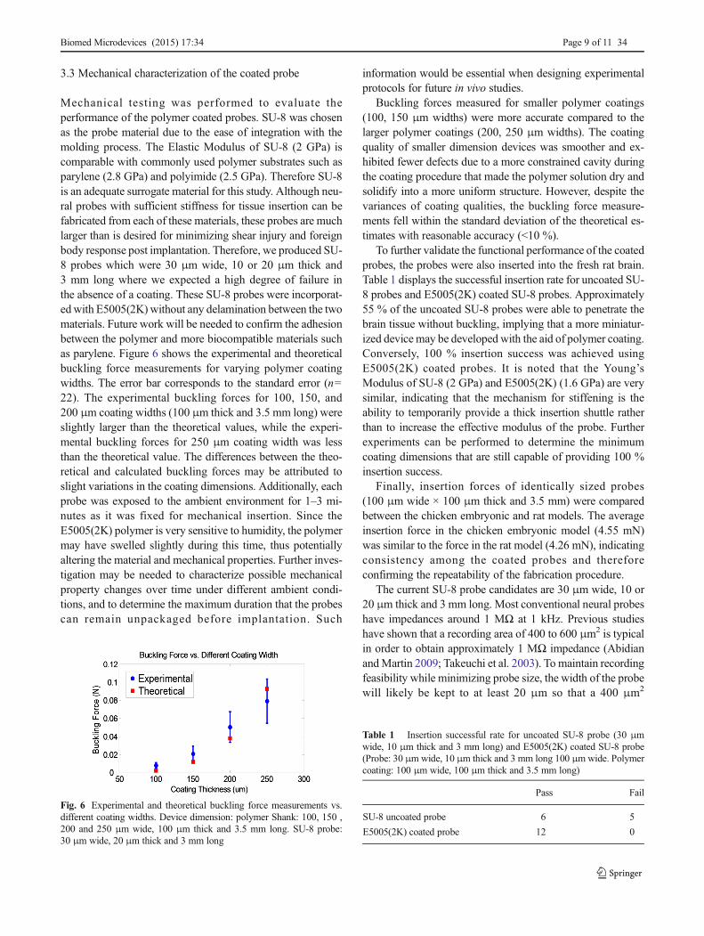
Mechanical testing was performed to evaluate theperformance of the polymer coated probes. SU-8 was chosenas the probe material due to the ease of integration with themolding process. The Elastic Modulus of SU-8 (2 GPa) iscomparable with commonly used polymer substrates such asparylene (2.8 GPa) and polyimide (2.5 GPa). Therefore SU-8is an adequate surrogate material for this study. Although neu-ral probes with sufficient stiffness for tissue insertion can befabricated from each of these materials, these probes are muchlarger than is desired for minimizing shear injury and foreignbody response post implantation. Therefore, we produced SU-8 probes which were 30 μm wide, 10 or 20 μm thick and3 mm long where we expected a high degree of failure inthe absence of a coating. These SU-8 probes were incorporat-edwith E5005(2K) without any delamination between the twomaterials. Future work will be needed to confirm the adhesionbetween the polymer and more biocompatible materials suchas parylene. Figure 6 shows the experimental and theoreticalbuckling force measurements for varying polymer coatingwidths. The error bar corresponds to the standard error (n=22). The experimental buckling forces for 100, 150, and200 μm coating widths (100 μm thick and 3.5 mm long) wereslightly larger than the theoretical values, while the experi-mental buckling forces for 250 μm coating width was lessthan the theoretical value. The differences between the theo-retical and calculated buckling forces may be attributed toslight variations in the coating dimensions. Additionally, eachprobe was exposed to the ambient environment for 1–3 mi-nutes as it was fixed for mechanical insertion. Since theE5005(2K) polymer is very sensitive to humidity, the polymermay have swelled slightly during this time, thus potentiallyaltering the material and mechanical properties. Further inves-tigation may be needed to characterize possible mechanicalproperty changes over time under different ambient condi-tions, and to determine the maximum duration that the probescan remain unpackaged before implantation. Such
information would be essential when designing experimentalprotocols for future in vivo studies.
Buckling forces measured for smaller polymer coatings(100, 150 μm widths) were more accurate compared to thelarger polymer coatings (200, 250 μm widths). The coatingquality of smaller dimension devices was smoother and ex-hibited fewer defects due to a more constrained cavity duringthe coating procedure that made the polymer solution dry andsolidify into a more uniform structure. However, despite thevariances of coating qualities, the buckling force measure-ments fell within the standard deviation of the theoretical es-timates with reasonable accuracy (<10 %).
To further validate the functional performance of the coatedprobes, the probes were also inserted into the fresh rat brain.Table 1 displays the successful insertion rate for uncoated SU-8 probes and E5005(2K) coated SU-8 probes. Approximately55 % of the uncoated SU-8 probes were able to penetrate thebrain tissue without buckling, implying that a more miniatur-ized device may be developed with the aid of polymer coating.Conversely, 100 % insertion success was achieved usingE5005(2K) coated probes. It is noted that the Young’sModulus of SU-8 (2 GPa) and E5005(2K) (1.6 GPa) are verysimilar, indicating that the mechanism for stiffening is theability to temporarily provide a thick insertion shuttle ratherthan to increase the effective modulus of the probe. Furtherexperiments can be performed to determine the minimumcoating dimensions that are still capable of providing 100 %insertion success.
Finally, insertion forces of identically sized probes(100 μm wide × 100 μm thick and 3.5 mm) were comparedbetween the chicken embryonic and rat models. The averageinsertion force in the chicken embryonic model (4.55 mN)was similar to the force in the rat model (4.26 mN), indicatingconsistency among the coated probes and thereforeconfirming the repeatability of the fabrication procedure.
The current SU-8 probe candidates are 30 μm wide, 10 or20 μm thick and 3 mm long. Most conventional neural probeshave impedances around 1 MΩ at 1 kHz. Previous studieshave shown that a recording area of 400 to 600 μm2 is typicalin order to obtain approximately 1 MΩ impedance (AbidianandMartin 2009; Takeuchi et al. 2003). To maintain recordingfeasibility while minimizing probe size, the width of the probewill likely be kept to at least 20 μm so that a 400 μm2
Fig. 6 Experimental and theoretical buckling force measurements vs.different coating widths. Device dimension: polymer Shank: 100, 150 ,200 and 250 μm wide, 100 μm thick and 3.5 mm long. SU-8 probe:30 μm wide, 20 μm thick and 3 mm long
Table 1 Insertion successful rate for uncoated SU-8 probe (30 μmwide, 10 μm thick and 3 mm long) and E5005(2K) coated SU-8 probe(Probe: 30 μmwide, 10 μm thick and 3 mm long 100 μmwide. Polymercoating: 100 μm wide, 100 μm thick and 3.5 mm long)
Pass Fail
SU-8 uncoated probe 6 5
E5005(2K) coated probe 12 0
Biomed Microdevices (2015) 17:34 Page 9 of 11 34
recording electrode, whereas the probe thickness can be fur-ther miniaturized (~5 μm).
4 Conclusion and future work
Smaller and more flexible neural probes are hypothesized toallow better long term integration with neural tissue by limit-ing the mechanical disruption of tissue and long-term shearingby being flexible enough to deformwith the surrounding braintissue duringmovement. However, such devices require inser-tion aids to provide enough mechanical support to penetratethe brain. In this work, a fabrication procedure was reportedthat produces miniaturized probes with a tyrosine-derivedpolycarbonate coating which provides sufficient rigidity fordevice insertion while degrading quickly (within hours) toenable long-term neural signal recordings. PDMS was usedas the substrate to provide sufficient bonding to conduct pho-tolithography for probe fabrication and polymer coating,while still allowing mechanical lifting off of the device. Thepolymer coated probes were mechanically characterizedex vivo to confirm probe performance. They were also char-acterized chemically to confirm that the polymer coatingseroded within 2 hours while leaving the probe intact. Thiswork also demonstrates the ability to reproduce consistentpolymer-coated probes.
Future work includes adapting the fabrication process re-ported here to develop polymer-coated probes made frommore inert and biocompatible materials such as parylene.Following characterization of the probes to identify suitabledevice dimensions, the microfabrication process will be ex-panded to functionalize the probes to create electrodes forsignal recording. Finally, the functionalized, polymer-coatedelectrodes will be implanted in vivo to assess glial tissue re-sponse, which will allow further refinement of the device de-sign and insertion protocol.
Acknowledgments This work is supported by New Jersey Commis-sion on Spinal Cord Research Award #CSCR12IRG001.
References
M.R. Abidian, D.C. Martin, Adv. Funct. Mater. 19, 573 (2009)A. Altuna, L. Menendez de la Prida, E. Bellistri, G. Gabriel, A. Guimerá,
J. Berganzo, R. Villa, L.J. Fernández, Biosens. Bioelectron. 37, 1(2012)
R. Biran, D.C. Martin, P.A. Tresco, Exp. Neurol. 195, 115 (2005)C.S. Bjornsson, S.J. Oh, Y.A. Al-Kofahi, Y.J. Lim, K.L. Smith, J.N.
Turner, S. De, B. Roysam, W. Shain, S.J. Kim, J. Neural Eng. 3,196 (2006)
S.L. Bourke, J. Kohn, Adv. Drug Deliv. Rev. 55, 447 (2003)F.I. Chang, R. Yeh, G. Lin, P.B. Chu, E.G. Hoffman, E.J. Kruglick, K.S.J.
Pister, M.H. Hecht, 117 (1995)
Z.-J. Chen, G.T. Gillies, W.C. Broaddus, S.S. Prabhu, H. Fillmore, R.M.Mitchell, F.D. Corwin, P.P. Fatouros, J. Neurosurg. 101, 314 (2004)
C.-H. Chen, S.-C. Chuang, Y.-T. Lee, S.-R. Yeh, Y.-C. Chang, D.-J. Yao,in Nano/Molecular Med. Eng. (NANOMED), 2009 I.E. Int. Conf.(2009), pp. 278–281
C.-H. Chen, S.-C. Chuang, H.-C. Su,W.-L. Hsu, T.-R. Yew, Y.-C. Chang,S.-R. Yeh, D.-J. Yao, Lab Chip 11, 1647 (2011)
S.-H. Cho, H.M. Lu, L. Cauller, M.I. Romero-Ortega, J.-B. Lee, G.A.Hughes, IEEE Sensors. J. 8, 1830 (2008)
J.J. Daly, J.R. Wolpaw, Lancet Neurol. 7, 1032 (2008)J.S. Ebersole, J. Clin. Neurophysiol. 14, 470 (1997)D.J. Edell, V.V. Toi, V.M.McNeil, L.D. Clark, Biomed. Eng. IEEE Trans.
39, 635 (1992)S.I. Ertel, J. Kohn, J. Biomed. Mater. Res. 28, 919 (1994)S.H. Felix, K.G. Shah, V.M. Tolosa, H.J. Sheth, A.C. Tooker, T.L.
Delima, S.P. Jadhav, L.M. Frank, S.S. Pannu, J. Vis. Exp. e50609(2013)
C. Foley, N. Nishimura, K. Neeves, C. Schaffer, W. Olbricht, Biomed.Microdevices 11, 915 (2009)
T. Fujita, T. Yoshimine, M. Maruno, T. Hayakawa, Acta Neurochir.(Wien) 140, 275 (1998)
P.J. Gilgunn, R. Khilwani, T.D. Y. Kozai, D.J. Weber, X.T. Cui, G. Erdos,O.B. Ozdoganlar, G.K. Fedder, in Micro Electro Mech. Syst.(MEMS), 2012 I.E. 25th Int. Conf. (2012), pp. 56–59
M.T. Giordana, A. Attanasio, P. Cavalla, A. Migheli, M.C. Vigliani, D.Schiffer, Neuropathol. Appl. Neurobiol. 20, 163 (1994)
C. González, M. Rodríguez, J. Neurosci. Methods 72, 189 (1997)T.W. Goodwin, R.A. Morton, Biochem. J. 40, 628 (1946)J.P. Harris, J.R. Capadona, R.H. Miller, B.C. Healy, K. Shanmuganathan,
S.J. Rowan, C. Weder, D.J. Tyler, J. Neural Eng. 8, 066011 (2011)L.R. Hochberg,M.D. Serruya, G.M. Friehs, J.A.Mukand,M. Saleh, A.H.
Caplan, A. Branner, D. Chen, R.D. Penn, J.P. Donoghue, Nature442, 164 (2006)
L.R. Hochberg, D. Bacher, B. Jarosiewicz, N.Y. Masse, J.D. Simeral, J.Vogel, S. Haddadin, J. Liu, S.S. Cash, P. van der Smagt, J.P.Donoghue, Nature 485, 372 (2012)
A.C. Hoogerwerf, K.D.Wise, IEEE Trans. Biomed. Eng. 41, 1136 (1994)K.A. Hooper, N.D. Macon, J. Kohn, J. Biomed. Mater. Res. 41, 443
(1998)J. Subbaroyan D.R. Kipke, in Eng. Med. Biol. Soc. 2006. EMBS’06. 28th
Annu. Int. Conf. IEEE (2006), pp. 3588–3591E. Kim, Y. Xia, G.M. Whitesides, J. Am. Chem. Soc. 118, 5722 (1996)B.J. Kim, J.T.W. Kuo, S.A. Hara, C.D. Lee, L. Yu, C.A. Gutierrez, T.Q.
Hoang, V. Pikov, E. Meng, J. Neural Eng. 10, 045002 (2013)D.R. Kipke, W. Shain, G. Buzsáki, E. Fetz, J.M. Henderson, J.F. Hetke,
G. Schalk, J. Neurosci. 28, 11830 (2008)N. Kishi, W.F. Chen, Y. Goto, J. Struct. Eng. 123, 313 (1997)T.D.Y. Kozai, N.B. Langhals, P.R. Patel, X. Deng, H. Zhang, K.L. Smith,
J. Lahann, N.A. Kotov, D.R. Kipke, Nat. Mater. 11, 1065 (2012a)T.D.Y. Kozai, A.L. Vazquez, C.L. Weaver, S.-G. Kim, X.T. Cui, J. Neural
Eng. 9, 066001 (2012b)A. Leskovar, L. Moriarty, J. Turek, I. Schoenlein, R. Borgens, J. Exp.
Biol. 203, 1783 (2000)D. Lewitus, K.L. Smith, W. Shain, J. Kohn, Acta Biomater. 7, 9 (2011)Y. Lu, T. Li, X. Zhao, M. Li, Y. Cao, H. Yang, Y.Y. Duan, Biomaterials
31, 5169 (2010)T. Lund, S.E. Hermansen, T.V. Andreasen, J.O. Olsen, B. Østerud, T.
Myrmel, K. Ytrehus, Thromb. Haemost. 104, 582 (2010)A. Mercanzini, P. Colin, J.C. Bensadoun, A. Bertsch, P. Renaud, IEEE
Trans. Biomed. Eng. 56, 1909 (2009)C. Ming, G. Xiaorong, G. Shangkai, X. Dingfeng, Biomed. Eng. IEEE
Trans. 49, 1181 (2002)J.K. Nguyen, D.J. Park, J.L. Skousen, A.E. Hess-Dunning, D.J. Tyler, S.J.
Rowan, C. Weder, J.R. Capadona, J. Neural Eng. 11, 056014 (2014)J.N. Patel, B. Kaminska, B.L. Gray, B.D. Gates, J.Micromech.Microeng.
18, 095028 (2008)
34 Page 10 of 11 Biomed Microdevices (2015) 17:34
G. Pfurtscheller, C. Neuper, C. Guger, W. Harkam, H. Ramoser, A.Schlogl, B. Obermaier, M. Pregenzer, Rehabil. Eng. IEEE Trans.8, 216 (2000)
V.S. Polikov, P.A. Tresco, W.M. Reichert, J. Neurosci. Methods 148, 1(2005)
R. Rojas, N.K. Harris, K. Piotrowska, J. Kohn, J. Polym. Sci. A Polym.Chem. 47, 49 (2009)
P.J. Rousche, R.A. Normann, J. Neurosci. Methods 82, 1 (1998)M. Salcman, M.J. Bak, Biomed. Eng. IEEE Trans. BME-20, 253 (1973)T. Saxena, L. Karumbaiah, E.A. Gaupp, R. Patkar, K. Patil, M. Betancur,
G.B. Stanley, R.V. Bellamkonda, Biomaterials 34, 4703 (2013)E.M. Schmidt, M.J. Bak, J.S. McIntosh, Exp. Neurol. 52, 496 (1976)J. Schut, D. Bolikal, I. Khan, A. Pesnell, A. Rege, R. Rojas, L. Sheihet, N.
Murthy, J. Kohn, Polymer (Guildf). 48, 6115 (2007)J.P. Seymour, D.R. Kipke, Biomaterials 28, 3594 (2007)C. Smith, K.D. Song, H. Yoon, W.-K. Kim, T. Zeng, L.D. Sanford,
834404 (2012)T. Stieglitz, H. Beutel, C. Blau, J.U. Meyer, Biomed. Tech. 42(Suppl),
449 (1997)T. Sun, W.M. Tsang, W.-T. Park, K. Cheng, S. Merugu, Microsyst.
Technol. (2014)D.H. Szarowski, M.D. Andersen, S. Retterer, A.J. Spence, M. Isaacson,
H.G. Craighead, J.N. Turner, W. Shain, Brain Res. 983, 23 (2003)S. Takeuchi, I. Shimoyama, J. Microelectromech. Syst. 9, 24 (2000)
S. Takeuchi, T. Suzuki, K. Mabuchi, H. Fujita, in Micro Electro Mech.Syst. 2003. MEMS-03 Kyoto. IEEE Sixt. Annu. Int. Conf. (2003), pp.367–370
S. Takeuchi, D. Ziegler, Y. Yoshida, K. Mabuchi, T. Suzuki, Lab Chip 5,519 (2005)
J.N. Turner, W. Shain, D.H. Szarowski, M. Andersen, S. Martins, M.Isaacson, H. Craighead, Exp. Neurol. 156, 33 (1999)
T.M. Vaughan, W.J. Heetderks, L.J. Trejo, W.Z. Rymer, M. Weinrich,M.M. Moore, A. Kübler, B.H. Dobkin, N. Birbaumer, E. Donchin,E.W.Wolpaw, J.R.Wolpaw, IEEE Trans. Neural Syst. Rehabil. Eng.11, 94 (2003)
R.J. Vetter, J.C.Williams, J.F. Hetke, E.A. Nunamaker, D.R. Kipke, IEEETrans. Biomed. Eng. 51, 896 (2004)
J.H.-C. Wang, B.P. Thampatty, Int. Rev. Cell Mol. Biol. 271, 301 (2008)T. Ware, D. Simon, D.E. Arreaga-Salas, J. Reeder, R. Rennaker, E.W.
Keefer, W. Voit, Adv. Funct. Mater. 22, 3470 (2012)J.C. Williams, R.L. Rennaker, D.R. Kipke, Brain Res. Protocol. 4, 303
(1999)J.C. Williams, J.A. Hippensteel, J. Dilgen, W. Shain, D.R. Kipke, J.
Neural Eng. 4, 410 (2007)K.D. Wise, J.B. Angell, A. Starr, Biomed. Eng. IEEE Trans. BME-17,
238 (1970)T. Zhu, P. Argyrakis, E. Mastropaolo, K.K. Lee, R. Cheung, J. Vac, Sci.
Technol. B Microelectron. Nanom. Struct. 25, 2553 (2007)
Biomed Microdevices (2015) 17:34 Page 11 of 11 34