co2-sensor with humidity and room ... - download.gira.de · device software has four logic gates....
TRANSCRIPT

KNXProduct documentation
Issue:24.03.2017
CO2-Sensor with humidity and room temperaturecontrollerOrder No. 2104 ..
21043200

Order No. 2104 ..
Table of ContentsProduct definition1 4.................................................................................................................
Product catalogue1.1 4...........................................................................................................Function1.2 4..........................................................................................................................
Mounting, electrical connection and operation2 6.................................................................
Safety instructions2.1 6...........................................................................................................Device components2.2 7........................................................................................................Fitting and electrical connection2.3 8......................................................................................Commissioning2.4 12.............................................................................................................
Technical data3 13....................................................................................................................
Software description4 14..........................................................................................................
Software specification4.1 14...................................................................................................Software "KNX CO2 sensor"4.2 15.........................................................................................
Scope of functions4.2.1 15.................................................................................................Notes on software4.2.2 18..................................................................................................Object table4.2.3 19...........................................................................................................
Object table push button interface4.2.3.1 19.................................................................Object table room temperature controller4.2.3.2 22......................................................Object table sensors4.2.3.3 36......................................................................................Object table logic gates4.2.3.4 40..................................................................................
Functional description4.2.4 41............................................................................................Application basics4.2.4.1 41..........................................................................................Push button interface4.2.4.2 43.....................................................................................
Introduction4.2.4.2.1 43.............................................................................................Function "no function"4.2.4.2.2 44............................................................................."Switching" function4.2.4.2.3 45................................................................................"Dimming" function4.2.4.2.4 46................................................................................."Venetian blind" function4.2.4.2.5 47.........................................................................Function"Value transmitter 1 byte / 2 byte"4.2.4.2.6 49............................................Function "Light scene extension with/without memory function"4.2.4.2.7 51............Response to bus voltage return4.2.4.2.8 52..............................................................Disabling function of the Inputs4.2.4.2.9 53..............................................................
Sensor function4.2.4.3 54..............................................................................................Temperature sensor4.2.4.3.1 54...............................................................................Humidity sensor4.2.4.3.2 55......................................................................................CO2 sensor4.2.4.3.3 56.............................................................................................Limiting values4.2.4.3.4 58........................................................................................
Room temperature controller4.2.4.4 64.........................................................................Operating modes and operating mode change-over4.2.4.4.1 64..............................Control algorithms and calculation of command values4.2.4.4.2 67.........................Adapting the control algorithms4.2.4.4.3 75..............................................................Operating mode switchover4.2.4.4.4 78....................................................................Temperature setpoints4.2.4.4.5 87............................................................................Room temperature measurement4.2.4.4.6 99...........................................................Command value and status output4.2.4.4.7 102.......................................................Disable functions of the room temperature controller4.2.4.4.8 109...........................
KNXProduct documentation
Page 2 of 171

Order No. 2104 ..
Valve protection4.2.4.4.9 110....................................................................................Logic gates4.2.4.5 111...................................................................................................Delivery state4.2.4.6 113...............................................................................................
Parameters4.2.5 114..........................................................................................................Parameter sensor4.2.5.1 114.........................................................................................Room temperature controller parameter4.2.5.2 125......................................................Push button interface parameter4.2.5.3 142..................................................................Logic gate parameter4.2.5.4 166...................................................................................
Appendix5 170...........................................................................................................................
Index5.1 170...........................................................................................................................
KNXProduct documentation
Page 3 of 171

Order No. 2104 ..
1 Product definition1.1 Product catalogue
Product name: CO2-Sensor
Use: Sensor
Design: FM (flush-mounted)
Order No. 2104 ..
1.2 FunctionThe device combines the functions of a KNX bus coupling unit, single-room temperaturecontroller with setpoint presetting, temperature and humidity sensor and CO2 sensor in one busdevice. The room temperature controller, humidity and CO2-Sensor functions are eachindependent function sections of the device with their own parameter blocks in the ETS. Thefunctions can be configured in the ETS.In addition, the device has two binary inputs that can be disabled during operation, and bymeans of which actuators can be controlled via KNX telegrams, e.g., for controlling fans orwindow drives. Through the combination of all functions it is possible to monitor the indoor airquality and to control measures for preserving the air quality via the bus.
CO2 sensor functionalityThe device can be used for determining the CO2 content of the ambient air. Depending onconfigured limiting values and current CO2 actual value, telegrams can be transmitted to theKNX for controlling fans or window drives. Four freely definable limiting values, which can beused by switching command telegrams for controlling actuators or indications, can beprogrammed for this purpose. The CO2 content determined can be transmitted to the bus as a2-byte measured value via a separate object and be made available to KNX displaycomponents or to supplementary filter units, for example.Since the measurement of correct values strongly depends on air pressure, a calibrationaccording to the height of the mounting location above NN (sea level) can be performed with theaid of the ETS parameters.
Room temperature controller functionalityThe device can be used for single-room temperature control. Depending on the operating mode,the current temperature set value and on the room temperature, a variable for heating or coolingcontrol can be sent to the KNX. The controller distinguishes between different operating modes(comfort, standby, night) each with their own temperature setpoints for heating or cooling.In addition to the heating or cooling basic level, activating an additional heater and/or coolingunit means that an additional heating or cooling unit can be used. In this connection, you canset the temperature setpoint difference between the basic and the additional level by aparameter in the ETS. For major deviations between the temperature setpoint and the actualtemperature, you can activate this additional level to heat up or cool down the room faster.You can assign different control algorithms to the basic and additional stages. For heating andcooling functions, you can select continuous or switching PI or switching 2-point feedbackcontrol algorithms.The room temperature can be recorded either by the internal or by an external temperaturesensor. A KNX communication object is available for the external temperature sensor by meansof which the temperature value received from the external bus, e.g. from a controller extension,can be integrated into the temperature detection.
Humidity sensor functionalityThe device can be used for determining the humidity of the ambient air. Depending onconfigured limiting values and the current air humidity, value switching telegrams can betransmitted to the KNX for controlling fans or window drives. The air humidity determined can betransmitted to the bus as a 2-byte measured value via a separate object, and in this way, be
Page 4 of 171
Product definition

Order No. 2104 ..
made available to KNX display components.The value of the air humidity measured by the humidity sensor together with the measured roomtemperature is used for calculating the dew point.
Dew point alarmThe dew point of water in the formal sense is the condensation point of pure water and thus avalue pair from air humidity and room temperature. The temperature value of the dew point, i.e.the dew point temperature, is normally equated with the dew point. This concerns thetemperature of the air with a specific humidity at which the condensation on an object iscurrently forming.The dew point temperature is calculated by the device on the basis of the determined roomtemperature and is adjusted by means of the Magnus formula. This is an approximation formulafor calculating the saturated vapour pressure depending on the temperature, which is used inmeteorology and building physics.The dew point temperature determined can be transmitted to the bus as a 2-byte value via aseparate object and be made available to KNX display components, for example. Once the dewpoint temperature has been reached, the device can transmit a dew point alarm to the bus in theform of switching or value telegrams. This dew point alarm can take place up to a maximumlead of 5 K in order to realise a pre-warning function.
Functionality of binary inputsThe device has a push-button interface with 2 independent channels and transmits telegrams tothe KNX after activation of a connected switch or push-button contact of a rocker or buttondepending on the ETS parameter setting. These can be, for instance, telegrams for switching orpush button control, for dimming or for controlling blinds. It is also possible to program valuetransmitter functions such as dimming value transmitters or light scene extensions. These inputsare lockable during operation. The insert for the presence detector is also possible.
Logic gatesIn order to implement logical dependencies from external states as well or to cascade, thedevice software has four logic gates. Each gate can have from one to a maximum of four inputs.The type of logic operation can be set as "AND", "OR", "EXCLUSIVE OR" or as "AND withfeedback" for each logic gate. In addition, each input can be operated normally or inverted.The communication objects of the outputs can be configured as 1-bit or 1-byte objects. Outputsthat transfer switching commands can also work inverted.The inputs can either be used separately with their own communication objects or can also, ifnecessary, be linked optionally to limiting values of the CO2- and humidity measurement, to theobjects of the dew point alarm or to output objects of other logic functions. The outputs can workwith a time delay if necessary. The transmission criterion for input event, output change andcyclical transmission can be set. Several logic gates can be combined with each other forcomplex logic operation functions.
GeneralThe device is flush mounted in a switchbox and covers the surface of a socket. The device is aso-called monoblock product. It does not require any separate bus coupling or additional powersupply.The programming mode of the device is indicated by a separate programming LED. It is locatedon the front of the design covers directly next to the programming button and continues flashinguntil an application is loaded. In this manner the device can be commissioned easily with theETS even in the installed state. Project design and commissioning of the device is performedusing the ETS 3.0d with Patch A or newer versions.
Page 5 of 171
Product definition

Order No. 2104 ..
2 Mounting, electrical connection and operation2.1 Safety instructionsElectrical equipment may only be installed and fitted by electrically skilled persons.Failure to observe the instructions may cause damage to the device and result in fire andother hazards.Do not use for safety-related gas measurements.During renovation work, protect the device against soiling through paint, wallpaperpaste, dust, etc. Device can be damaged.Do not clean or store the device with organic solvents or expose it to their vapours. Donot stick any adhesive labels. Do not store device in packaging or environments thatcontain softening agents, e.g. bubble wrap or polystyrene. Before starting renovationwork, remove the device from the system and store it in a suitable place. The function ofthe temperature and humidity sensor may be permanently impaired.Danger of electric shock on the KNX installation. Do not connect any external voltage tothe inputs. The device might be damaged, and the SELV potential on the KNX bus linewill no longer be available.
Page 6 of 171
Mounting, electrical connection and operation

Order No. 2104 ..
2.2 Device components
Figure 1: Device components CO2 Sensor
(1) Device connection terminal insert(2) Design frame(3) Electronics cover(4) Cover(5) Programming button and LEDs(6) Locking screw (plastic)(7) Sensor window CO2 sensor
Page 7 of 171
Mounting, electrical connection and operation
Order No. 2104 ..
2.3 Fitting and electrical connectionDANGER!When mounting with 230 V devices under a common cover, e.g. socket outlets,there is a danger of electrical shocks in the event of a fault!Electrical shocks can be fatal.Only use the preassembled plastic screw as locking screw!
CAUTION!Electrostatic dischargesDevice damage.Only operate the device with cover.
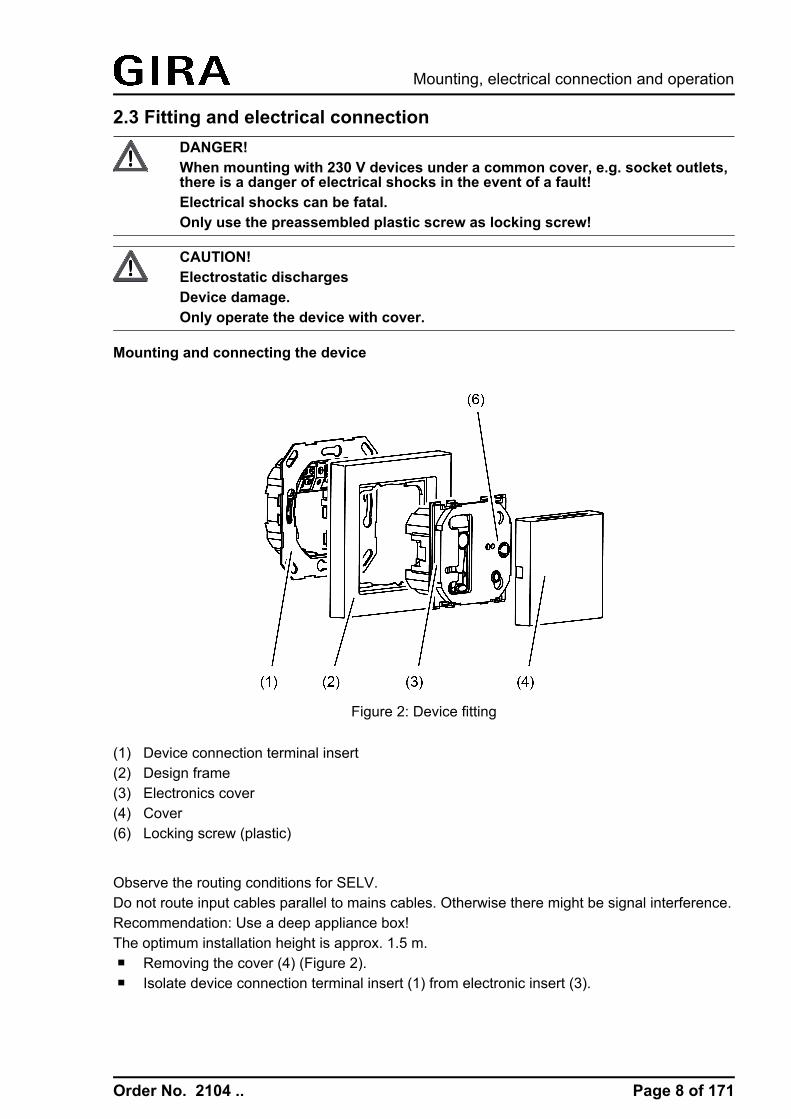
Mounting and connecting the device
Figure 2: Device fitting
(1) Device connection terminal insert(2) Design frame(3) Electronics cover(4) Cover(6) Locking screw (plastic)
Observe the routing conditions for SELV.Do not route input cables parallel to mains cables. Otherwise there might be signal interference.Recommendation: Use a deep appliance box! The optimum installation height is approx. 1.5 m. o Removing the cover (4) (Figure 2).o Isolate device connection terminal insert (1) from electronic insert (3).
Page 8 of 171
Mounting, electrical connection and operation

Order No. 2104 ..
Figure 3: Device connection terminal insert with connections
(8) Connecting strip binary inputs(9) KNX connection
o Insert the stripped bus line into the device connection terminal (9) in the device connectionterminal insert (Figure 3)
Figure 4: Connection of binary inputs
1..3 Not assigned4 Connection binary input E15 Connection binary input E26 Reference potential E1, E2
o Window contacts, NO contact or NC contact push-buttons can be connected to deviceconnection terminal 4, 5 and 6 of the connecting strip binary inputs (8).
o Insert device connection terminal insert (1) in appliance box. Note label OBEN / TOP. Thebus connection must be to the right and below.
o Fit the Design frame (2) on device connection terminal insert (1).o Insert the electronics cover (3) into the device connection terminal insert in the correct
orientation.o Fasten the electronics cover with the locking screw (6).
Page 9 of 171
Mounting, electrical connection and operation

Order No. 2104 ..
o Reattach the cover (4).
i Do not use the device in multiple combinations with other FM devices as their heatgeneration can influence the temperature and humidity measurement of the controller.
i Do not mount the device near sources of interference such as electric cookers,refrigerators, draughts or direct sunlight. This also influences the temperature and humidityreading of the controller.
Dismantling the device
Figure 5: Device dismantling
Design cover and electronics cover should be dismantled during painting and decorating work.o Insert screwdriver in slot on the bottom of the cover and raise it carefully.i Do not damage cover and design frame.o Loosen locking screw in the electronics cover.o Remove electronics cover from device connection terminal insert.
Page 10 of 171
Mounting, electrical connection and operation

Order No. 2104 ..
i During the subsequent fitting, the cover must be mounted again onto the respective insert.Therefore, please pay attention to the correct labelling of the cover and insert during thedismantling and label these accordingly.
Page 11 of 171
Mounting, electrical connection and operation

Order No. 2104 ..
2.4 CommissioningLoading the physical address and application softwareThe commissioning of the device is basically confined to programming of the physical addressand the application data with the ETS.Project design and commissioning of the device using the ETS 3.0d with Patch A or newerversions.The device is connected and ready for operation.An appropriate device must be created and configured in the ETS project.
Figure 6: Location of the programming button and LED
The programming button is located behind the blank cover (4) on the electronics cover (3) .Theprogramming button is located behind the blank cover (4) on the electronics cover (3)(Figure 6).o Remove the blank cover (4) if it is already mounted.o Activating Programming mode: push the programming button (5).
The programming LED (5) lights up red.o Program the physical address with the help of the ETS.
The programming LED goes out.o Record the physical address on the device connection terminal insert and on the back of
the electronics cover.i Observe the correct assignment of inserts and covers when assembling after painting or
wallpapering work.o Mount blank cover.o Load the application data into the device using the ETS.i If the device was programmed with wrong application data, the device is without function
after the commissioning.
Page 12 of 171
Mounting, electrical connection and operation

Order No. 2104 ..
3 Technical data GeneralProtection class IIITest mark KNX/EIBAmbient temperature -5 ... +45 °CStorage/transport temperature +10 ... +50 °CStorage/transport humidity 20 ... 60 % rel. humidity
KNXKNX medium TPCommissioning mode S-modeRated voltage KNX DC 21 ... 32 V SELVCurrent consumption KNX typ. 12.5 mACurrent consumption KNX max. 25 mA (4 s/15 s as a cycle)Connection mode KNX device connection terminal
Binary inputsCable length max. 5 mCable type J-Y(St)Y 2 x 2 x 0.8 mm
CO2 sensorMeasuring range 0 ... 2000 ppm
Humidity sensorsMeasuring range 10 ... 95 % rel. humidity
Temperature sensorsMeasuring range -5 ... +45 °C
Page 13 of 171
Technical data
Order No. 2104 ..
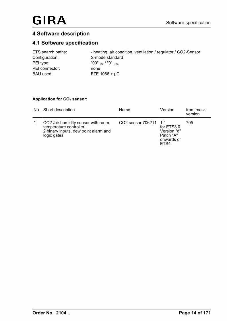
4 Software description4.1 Software specificationETS search paths: - heating, air condition, ventilation / regulator / CO2-SensorConfiguration: S-mode standardPEI type: "00"Hex / "0" Dec
PEI connector: noneBAU used: FZE 1066 + µC
Application for CO2 sensor:
No. Short description Name Version from maskversion
1 CO2-/air humidity sensor with roomtemperature controller,2 binary inputs, dew point alarm andlogic gates.
CO2 sensor 706211 1.1for ETS3.0Version "d"Patch "A"onwards orETS4
705
Page 14 of 171
Software specification

Order No. 2104 ..
4.2 Software "KNX CO2 sensor"4.2.1 Scope of functions
Pushbutton interface funcionality
General- Free allocation of the functions switching, dimming, Venetian blind and value transmitter to
max. 2 inputs.- Disable object for disabling individual inputs (polarity of the disable object is adjustable).- Delay on bus voltage return and debouncing time centrally adjustable.- The behaviour on bus voltage return can be configured separately for each input.- Telegram rate limit generally adjustable for all inputs.Switching function- Two independent switching objects are available for each input, switching commands can
be configured individually.- Command can be set independently for rising and falling edge. Executable switching
commands may include "ON", "OFF", "TOGGLE" or "no reaction".Dimming function- The choice between single-surface and dual-area operation is possible. Executable
switching commands may include "Brighter (ON)", "darker (OFF)" or "TOGGLE".- Time between dimming and switching and also the dimming step width is adjustable.- Cyclical transmission of telegram repetitions as well as transmission of a stop telegram at
the end of a dimming procedure is possible."Blind" function- Command can be set independently for rising edge. Executable switching commands may
include "no function", "UP", "DOWN" or "TOGGLE".- The operation concept is configurable (short – long – short or long – short).- In the operation concept Short – Long – Short, the time between short and long-time
operation is adjustable.- The slat adjusting time is adjustable. This is the time during which a MOVE command can
be terminated by releasing a push-button at the input.Function value transmitter (dimming, temperature, brightness)- The edge (push-button as NO contact, push-button as NC contact, switch) and the value to
be transmitted are configurable on edge.- When programming as a push-button, the value for the value transmitter can be adjusted
by a long button-press.Function light scene extension- Configuration as light scene extension with or without memory function. In the light scene
extension with memory function, a light scene can be stored by a long press of theconnected push-button.
- The edge (push-button as NO contact, push-button as NC contact, switch) and the value tobe transmitted are configurable on edge.
Room temperature controller functionality
General- 4 various operating modes can be activated: Comfort, Standby, Night and Frost/heat
protection- The operating mode switchover is performed via 1-byte object according to the KNX
specification or using up to four individual 1-bit objects.Heating / cooling- The operating modes "Heating", "Cooling" or "Heating and Cooling" are available with or
without additional level.
Page 15 of 171
Software "KNX CO2 sensor"Scope of functions

Order No. 2104 ..
- The control algorithms of the temperature control are configurable, either the switching2-point feedback control, the switching PI control (PWM) or the continuous PI control.
- The command value output 1-bit (switching) or 1-byte (continuous).- The adjustable control parameters for the PI control are "Proportional range" and "Reset
time", for the 2-point feedback control "Hysteresis".Setpoint values- Each operating mode can be assigned its own temperature-setpoints (for heating and/or
cooling).- The setpoints for the additional level are derived by a configurable level offset from the
values of the basic setpoint.- The basic setpoint shift is possible by means of communication objects.Functions- Switching between "Heating" and "Cooling" can be automatic or object-oriented.- Deactivating the feedback control possible using separate 1-bit objects.- The comfort extension is possible by pressing a configurable presence button or presence
detector in the night or frost/heat protection mode.- The length of the comfort extension can be parameterized.- The status information is configurable and can be transmitted to the bus via an object
(1-byte / 1-bit).- Deactivating the feedback control or the additional level is possible using separate 1-bit
objects.Room temperature measurement- The room temperature can be measured by means of an internal or external room
temperature sensor. The external temperature sensor must be a KNX temperature sensorcoupled via the bus. Alternatively, both temperature sensors can be combined together.The determination of the measured value from the internal to external sensor isconfigurable.
- The polling time of the external temperature sensor is settable.- The change interval for the automatic transmission of the actual temperature can be
defined in the ETS. Cyclical transmission of the room temperature is possible, too.- The room temperature measurement (actual value) can be adjusted separately for the
internal and external sensor using parameters.- The frost protection mode switch-over is possible by the window status or by the automatic
frost protection.Actuating variable output- The separate or shared command value output in heating and cooling mode is possible.
This produces one or two command value objects for each level.- Normal or inverted command value output is configurable- Automatic transmission and cycle time for command value output are configurable.
Humidity sensor functionality
Humidity measurement- The humidity is measured by the integrated measuring element.- Two limiting values can be assigned to the humidity measured value, and if exceeded or
fallen short of, ventilation controllers can be activated, for example.Dew point determination- The dew point temperature is calculated by the device on the basis of the determined room
temperature.- The determined humidity value of the sensor is adjusted by means of the Magnus formula
which is an approximation formula for calculating the saturated vapour pressure dependingon the temperature. It is very accurate (< 0.22 %) in the range between 0°C and 100°C andis primarily used in meteorology and building physics for determining the dew point.
Page 16 of 171
Software "KNX CO2 sensor"Scope of functions

Order No. 2104 ..
CO2 controller functionalityi After switch-on, the CO2 sensor requires a warm-up period of up to 5 minutes, until normal
operation is reached.The automatic calibration method is only available in the case of permanent power supplyand after 24 hours for the first time.
CO2 measurement- The CO2 is measured by means of the integrated sensor module.- The "height of the location above sea level" is configurable because the exact measured
value of the CO2 sensor is air pressure dependent.Limiting values- Four limiting values can be assigned to the CO2 measured value, and if exceeded or fallen
short of, ventilation controllers can be activated, for example.- The hysteresis and behaviour can be specified for all limiting values should the limiting
value be exceeded or undershot.- A switch-on and switch-off delay can be configured for all limiting values (also applies to
cyclical transmission).- The transmission criterion cyclical transmission is configurable for all limiting values.
Logic gates functionality- Up to four logic gates with one up to a maximum of four inputs can be configured. Each of
the inputs can be operated normal or inverted.- Possible logic operations are "AND", "OR", "Exclusive OR" or "AND with return".- The communication objects of the outputs can be configured as 1-bit or 1-byte objects.- The transmission criterion for input event, output change and cyclical transmission can be
set.- The transmission delay can be configured individually for all logic gates.
Page 17 of 171
Software "KNX CO2 sensor"Scope of functions

Order No. 2104 ..
4.2.2 Notes on software
ETS project design and commissioningFor project design and commissioning of the device, ETS3.0 from Version "d" Patch "A"onwards or ETS4 is required. Through use of these ETS version, advantages are gained withregard to the programming process (differential download).The necessary product database is offered in the *.VD4 format.
A plug-in integrated in the ETS product database permits the configuration.
Page 18 of 171
Software "KNX CO2 sensor"Notes on software

Order No. 2104 ..
4.2.3 Object table
Number of communication objects: 139(max. object number 138 - gaps in between)
Number of addresses (max): 254
Number of assignments (max): 255
Dynamic table management no
4.2.3.1 Object table push button interface
Objects of the push button interface
Function: SwitchingObject
h0, 1
FunctionSwitching object 1.1
NameB.Channel 1 / 2
Type1-bit
DPT1,001
FlagC, W, T,(R)1
Description 1-bit object for transmission of switching telegrams (ON, OFF, TOGGLE).
Function: SwitchingObject
h2, 3
FunctionSwitching object 1.2
NameB.Channel 1 / 2
Type1-bit
DPT1,001
FlagC, W, T,(R) 1
Description 1-bit object for transmission of switching telegrams (ON, OFF, TOGGLE).
Function: DimmingObject
h0, 1
FunctionSwitching
NameB.Channel 1 / 2
Type1-bit
DPT1,001
FlagC, W, T,(R)1
Description 1-bit object for transmission of switching telegrams (ON, OFF, TOGGLE).
Function: DimmingObject
h2, 3
FunctionDimming
NameB.Channel 1 / 2
Type4-bit
DPT3,007
FlagC, W, T,(R)1
Description 4-bit object for the transmission of relative dimming telegrams.
Function: Venetian blindObject
h0, 1
FunctionShort time operation
NameB.Channel 1 / 2
Type1-bit
DPT1,007
FlagC, T (R)1
Description 1-bit object for the transmission of telegrams with which a Venetian blind orshutter drive motor can be stopped or with which the blind slats can beadjusted by short time operation.
1: Each communication object can be read out. For reading, the R-flag must be set.
Page 19 of 171
Software "KNX CO2 sensor"Object table

Order No. 2104 ..
Function: Venetian blindObject
h2, 3
FunctionLong-time operation
NameB.Channel 1 / 2
Type1-bit
DPT1,008
FlagC, W, T,(R)1
Description 1-bit object for the transmission of telegrams with which a Venetian blind orshutter drive motor can be can be moved upwards or downwards.
Function: Value transmitterObject
h0, 1
FunctionDimming value
NameB.Channel 1 / 2
Type1bytes
DPT5,001
FlagC, T (R)1
Description 1-byte object for the transmission of values from 0 to 255 (corresponding tovalues from 0 % to 100 %). If the adjustment of the value is enabled, theobject can transmit telegrams cyclically after long actuation with which thevalue can be reduced or increased by a presettable amount.
Function: Value transmitterObject
h0, 1
FunctionScene extension
NameB.Channel 1 / 2
Type1bytes
DPT18,001
FlagC, T (R)1
Description 1-byte object for recalling or storing one of a maximum of 64 scenes of ascene push-button or actuator with scene function.
Function: Value transmitterObject
h0, 1
FunctionTemperature value
NameB.Channel 1 / 2
Type2bytes
DPT9,001
FlagC, T (R)1
Description 2 -byte object for the transmission of a temperature value from 0 °C to 40 °C.If the adjustment of the value is enabled, the object can transmit telegramscyclically after a long press with which the value can be reduced or increasedby 1 K.
Function: Value transmitterObject
h0, 1
FunctionBrightness value
NameB.Channel 1 / 2
Type2bytes
DPT9,004
FlagC, T (R)1
Description 2-byte object for the transmission of a brightness level value from 0 to 1500lux. If the adjustment of the value is enabled, the object can transmit cyclicaltelegrams after a long press with which the value can be reduced or increasedby 50 lux.
1: Each communication object can be read out. For reading, the R-flag must be set.
Page 20 of 171
Software "KNX CO2 sensor"Object table

Order No. 2104 ..
Function: Disable – switchingObject
h4, 5
FunctionDisabling switching object 1.1
NameB.Disable channel1 / 2
Type1-bit
DPT1,001
FlagC, W, (R)1
Description 1-bit object by which the switching object can be disabled and enabled again(polarity and behaviour at the beginning and end of the disabling function areconfigurable).
Function: Disable – switchingObject
h6, 7
FunctionDisabling switching object 1.2
NameB.Disable channel1 / 2
Type1-bit
DPT1,001
FlagC, W, (R)1
Description 1-bit object by which the switching object can be disabled and enabled again(polarity and behaviour at the beginning and end of the disabling function areconfigurable).
Function: Disabling – Dimming/Venetian blind/Value transmitterObject
h4, 5
FunctionDisabling
NameB.Disable channel1 / 2
Type1-bit
DPT1,001
FlagC, W, (R)1
Description 1-bit object by which the function can be disabled and enabled again (polarityand behaviour at the beginning and end of the disabling function areconfigurable).
1: Each communication object can be read out. For reading, the R-flag must be set.
Page 21 of 171
Software "KNX CO2 sensor"Object table

Order No. 2104 ..
4.2.3.2 Object table room temperature controller
Objects for room temperature measurement
Function: Room temperature measurementObject
h23
FunctionActual-temperature
NameC.Output
Type2bytes
DPT9,001
FlagC, -, T, R
Description 2-byte object to output the actual temperature (room temperature) determinedby the controller and used for the room temperature control. Possible valuerange: -99.9 °C to +99.9 °C / Measuring range of internal temperature sensor:0 °C to +40 °C.The temperature value is always output in the format "°C".
Function: Room temperature measurementObject
h24
FunctionReceived temperature
NameC.Input
Type2bytes
DPT9,001
FlagC, W, -,(R)1
Description 2-byte object for coupling an external KNX room temperature sensor. Thuscascading of multiple temperature sensors for room temperaturemeasurement. Possible range of values: -99.9 °C to +99.9 °C.The temperature value must always be specified in the format "°C".
Objects for setpoint temperature specification
Function: Setpoint temperature specificationObject
h26
FunctionBasic setpoint
NameC.Input
Type2bytes
DPT9,001
FlagC, W, -,(R)1
Description 2-byte object for external specification of the basic setpoint for relative setpointspecification. Depending on the operating mode, the possible range of valuesis limited by the configured frost protection and/or heat protection temperature.The controller rounds the temperature values received via the objectdepending on the configured interval of the basic setpoint shift (0.1 K or 0.5K).The temperature value must always be specified in the format "°C".
Function: Setpoint temperature specificationObject
h26
FunctionSetpoint active operatingmode
NameC.Input
Type2bytes
DPT9,001
FlagC, W, (T),(R) 1
Description 2-byte object for external setting of a setpoint for absolute setpoint presetting.Depending on the operating mode, the possible range of values is limited bythe configured frost protection and/or heat protection temperature. Thecontroller rounds the temperature values received via the object to 0.1 K.The temperature value must always be specified in the format "°C".The setpoint modified by the setpoint shift can be reported back to the bus viathe object by setting the "Transmit" flag.
1: Each communication object can be read out. For reading, the R-flag must be set.
Page 22 of 171
Software "KNX CO2 sensor"Object table

Order No. 2104 ..
Objects for operating mode change-over
Function: Operating mode switchoverObject
h28
FunctionOperating mode switchover
NameC.Input
Type1bytes
DPT20,102
FlagC, W, T,(R)1
Description 1-byte object for change-over of the operating mode of the controlleraccording to the KNX specification. This object is only available in this waywhen the operating mode switchover is to take place over 1 byte (parameter-dependent).
Function: Operating mode switchoverObject
h32
FunctionOperating mode forced-control
NameC.Input
Type1bytes
DPT20,102
FlagC, W, T,(R)1
Description 1-byte object for forced change-over (highest priority) of the operating mode ofthe controller according to the KNX specification. This object is only availablein this way when the operating mode switchover is to take place over 1 byte(parameter-dependent).
Function: Operating mode switchoverObject
h28
FunctionComfort mode
NameC.Input
Type1-bit
DPT1,001
FlagC, W, T,(R)1
Description 1-bit object for change-over to the "Comfort" operating mode. This object isonly available in this way when the operating mode change-over is to takeplace over 4 x 1 bit (parameter-dependent).
Function: Operating mode switchoverObject
h29
FunctionStandby mode
NameC.Input
Type1-bit
DPT1,001
FlagC, W, T,(R)1
Description 1-bit object for change-over to the "Standby" operating mode. This object isonly available in this way when the operating mode change-over is to takeplace over 4 x 1 bit (parameter-dependent).
Function: Operating mode switchoverObject
h30
FunctionNight operation
NameC.Input
Type1-bit
DPT1,001
FlagC, W, T,(R)1
Description 1-bit object for change-over to the "Night" operating mode. This object is onlyavailable in this way when the operating mode change-over is to take placeover 4 x 1 bit (parameter-dependent).
1: Each communication object can be read out. For reading, the R-flag must be set.
Page 23 of 171
Software "KNX CO2 sensor"Object table

Order No. 2104 ..
Function: Operating mode switchoverObject
h31
FunctionFrost/ heat protection
NameC.Input
Type1-bit
DPT1,001
FlagC, W, T,(R) 1
Description 1-bit object for change-over to the "Frost / heat protection" operating mode.This object is only available in this way when the operating mode change-overis to take place over 4 x 1 bit (parameter-dependent).
Function: Operating mode switchover presence objectObject
h33
FunctionPresence object
NameC.Input / Output
Type1-bit
DPT1,018
FlagC, W, T,(R)1
Description 1-bit object through which a presence detector or an external presence buttoncan be linked to the controller. The object also transmits the state of apresence button of the device to the bus.Polarity: presence detected = "1", presence not detected = "0".
Function: Operating mode switchover presence objectObject
h33
FunctionPresence object
NameC.Input
Type1-bit
DPT1,018
FlagC, W, -,(R)1
Description 1-bit object through which a presence detector can be linked to the controller.Polarity: presence detected = "1", presence not detected = "0".
Function: Operating mode change-over window statusObject
h34
FunctionWindow status
NameC.Input
Type1-bit
DPT1,019
FlagC, W, -,(R)1
Description 1-bit object for the coupling of window contacts. Polarity:Window open = "1", window closed = "0".
Object for operating mode switchover
Function: Operating mode switchoverObject
h35
FunctionHeating / cooling switchover 2
NameC.Input
Type1-bit
DPT1,100
FlagC, W, T,(R)1
Description 1-bit object for specifying the operating mode ("Heating" or "Cooling"). Onlyvisible if "Change-over between heating and cooling = via object".Object value "1" = Heating; Object value "0" = Cooling.
1: Each communication object can be read out. For reading, the R-flag must be set.
2: This object is only active with one control circuit in the "heating and cooling" or "basic/additional - heating/ cooling" mixed-mode operation.
Page 24 of 171
Software "KNX CO2 sensor"Object table

Order No. 2104 ..
Function: Operating mode switchoverObject
h35
FunctionHeating / cooling switchover 1
NameC.Output
Type1-bit
DPT1,100
FlagC, -, T, (R)2
Description 1 bit object to transmit the automatically set operating mode of the controller.Object value "1" = Heating; Object value "0" = Cooling.
Object for controller status
Function: Status signalObject
h36
FunctionController status
NameC.Output
Type1bytes
DPT--- 3
FlagC, -, T, (R) 2
Description 1-byte object used by the controller to output the current state of operation(e.g. to a controller extension).Only when "Controller status" = "Controller general".
Function: Status signalObject
h54
FunctionStatus signal addition
NameC.Output
Type1bytes
DPT--- 4
FlagC, -, T, (R) 2
Description 1-byte object used by the controller to output the current enlarged state ofoperation (e.g. to a controller extension).Only when "Controller status" = "Controller general".
Function: Status signalObject
h36
FunctionController status ...
NameC.Output
Type1-bit
DPT1,001
FlagC, -, T, (R)2
Description 1-bit object for single status feedback of configured controller functions. Thisobject is only available in this way when a part of the controller status is to betransmitted singly as 1-bit information (parameter-dependent).
1: This object is only active with one control circuit in the "heating and cooling" or "basic/additional - heating/ cooling" mixed-mode operation.
2: Each communication object can be read out. For reading, the R-flag must be set.
3: Non-standardised DP type (in accordance with KNX AN 097/07 rev 3).
4: Non-standardised DP type.
Page 25 of 171
Software "KNX CO2 sensor"Object table

Order No. 2104 ..
Function: Status signalObject
h36
FunctionKNX status operating mode
NameC.Output
Type1bytes
DPT20,102
FlagC, -, T, (R)1
Description 1-byte object used by the controller to output the current operating mode. Thisobject is generally used to enable controller extensions to display thecontroller operating mode correctly in the KNX compliant status display.Therefore this object should be connected with controller extensions if theKNX compliant status feedback is not configured.Only when "Controller status" = "KNX compliant".
Function: Status signalObject
h55
FunctionKNX status
NameC.Output
Type2bytes
DPT22,101
FlagC, -, T, (R)1
Description 2-byte object that the controller uses to display elementary basic functions in aKNX-harmonised manner.Only when "Controller status" = "KNX compliant".
Function: Status signalObject
h56
FunctionKNX status forced oper.mode
NameC.Output
Type1bytes
DPT20,102
FlagC, -, T, (R)1
Description 1-byte object used by the controller to output the operating mode in the eventof forced position. This object is generally used to enable controller extensionsto display the controller operating mode correctly in the KNX compliant statusdisplay. Therefore this object should be connected with controller extensions ifthe KNX compliant status feedback is not configured.Only when "Controller status" = "KNX compliant".
Objects for command value limit
Function: Command value limitObject
h57
FunctionCommand value limit
NameC.Input
Type1-bit
DPT1,001
FlagC, W, -, (R)1
Description 1-bit object for activating or deactivating the command value limit.Polarity: Limitation activated ="1", Limitation deactivated = "0".
1: Each communication object can be read out. For reading, the R-flag must be set.
Page 26 of 171
Software "KNX CO2 sensor"Object table

Order No. 2104 ..
Objects for heating / cooling signal functions
Function: Status signalObject
h37
FunctionHeating indication
NameC.Output
Type1-bit
DPT1,001
FlagC, -, T, (R)1
Description 1-bit object for the controller to report a request for heating energy. Objectvalue = "1": energy request, object value = "0": no energy request.
Function: Status signalObject
h38
FunctionCooling indication
NameC.Output
Type1-bit
DPT1,001
FlagC, -, T, (R)1
Description 1-bit object for the controller to report a request for cooling energy. Objectvalue = "1": energy request, object value = "0": no energy request.
Objects for controller disabling functions
Function: Disabling function (room temperature regulator)Object
h40
FunctionDisable controller
NameC.Input
Type1-bit
DPT1,001
FlagC, W, -, (R) 1
Description 1-bit object for deactivating the controller (activating dew point operation).Polarity: Controller deactivated = "1", controller activated = "0".
Function: Disabling function (room temperature regulator)Object
h41
FunctionDisable additional level 2
NameC.Input
Type1-bit
DPT1,001
FlagC, W, -,(R)1
Description 1-bit object for deactivating the additional level of the controller. Polarity:Additional level deactivated = "1", additional level activated = "0". This object isonly available in this way if two-level heating or cooling operation isconfigured.
Objects for command value output for heating
Function: Command valueObject
h42
FunctionCommand value for heating /command value, basicheating
NameC.Output
Type1bytes
DPT5,001
FlagC, -, T, (R)1
Description 1-byte object to output the continuous command value of the heating mode. Intwo-level heating mode, command value output for the basic heating. Thisobject is only available in this way if the type of feedback control is configuredto "Continuous PI control".
1: Each communication object can be read out. For reading, the R-flag must be set.
2: This object is only visible with activated additional stage.
Page 27 of 171
Software "KNX CO2 sensor"Object table

Order No. 2104 ..
Function: Command valueObject
h42
FunctionCommand value for heating(PWM) / command value,basic heating (PWM)
NameC.Output
Type1-bit
DPT1,001
FlagC, -, T, (R)1
Description 1-bit object to output the PWM command value of the heating mode. In two-level heating mode, command value output for the basic heating. This object isonly available in this way if the type of feedback control is configured to"Switching PI control (PWM)".
Function: Command valueObject
h42
FunctionCommand value for heating /command value, basicheating
NameC.Output
Type1-bit
DPT1,001
FlagC, -, T, (R)1
Description 1-bit object to output the switching command value of the heating mode. Intwo-level heating mode, command value output for the basic heating. Thisobject is only available in this way if the type of feedback control is configuredto "Switching 2-point feedback control".
Object for heating command value output and combined valve heating/cooling
Function: Command valueObject
h42
FunctionCommand value forheating/cooling / basic level
NameC.Output
Type1bytes
DPT5,001
FlagC, -, T, (R)1
Description 1-byte object to output the combined continuous command value of theheating and cooling mode. In two-level heating/cooling mode, command valueoutput for the basic level This object is only available in this way if thecommand values for heating and cooling mode are output to a shared object(parameter-dependent). The type of feedback control must also be configuredto "Continuous PI control".
Function: Command valueObject
h42
FunctionCommand value forheating/cooling (PWM) /basic level (PWM)
NameC.Output
Type1-bit
DPT1,001
FlagC, -, T, (R)1
Description 1-bit object to output the combined PWM command value of the heating andcooling mode. In two-level heating/cooling mode, command value output forthe basic level This object is only available in this way if the command valuesfor heating and cooling mode are output to a shared object (parameter-dependent). The type of feedback control must also be configured to"Switching PI control (PWM)".
1: Each communication object can be read out. For reading, the R-flag must be set.
Page 28 of 171
Software "KNX CO2 sensor"Object table

Order No. 2104 ..
Function: Command valueObject
h42
FunctionCommand value forheating/cooling / basic level
NameC.Output
Type1-bit
DPT1,001
FlagC, -, T, (R)1
Description 1-bit object to output the combined switching command value of the heatingand cooling mode. In two-level heating/cooling mode, command value outputfor the basic level This object is only available in this way if the commandvalues for heating and cooling mode are output to a shared object (parameter-dependent). The type of feedback control must also be configured to"Switching 2-point feedback control".
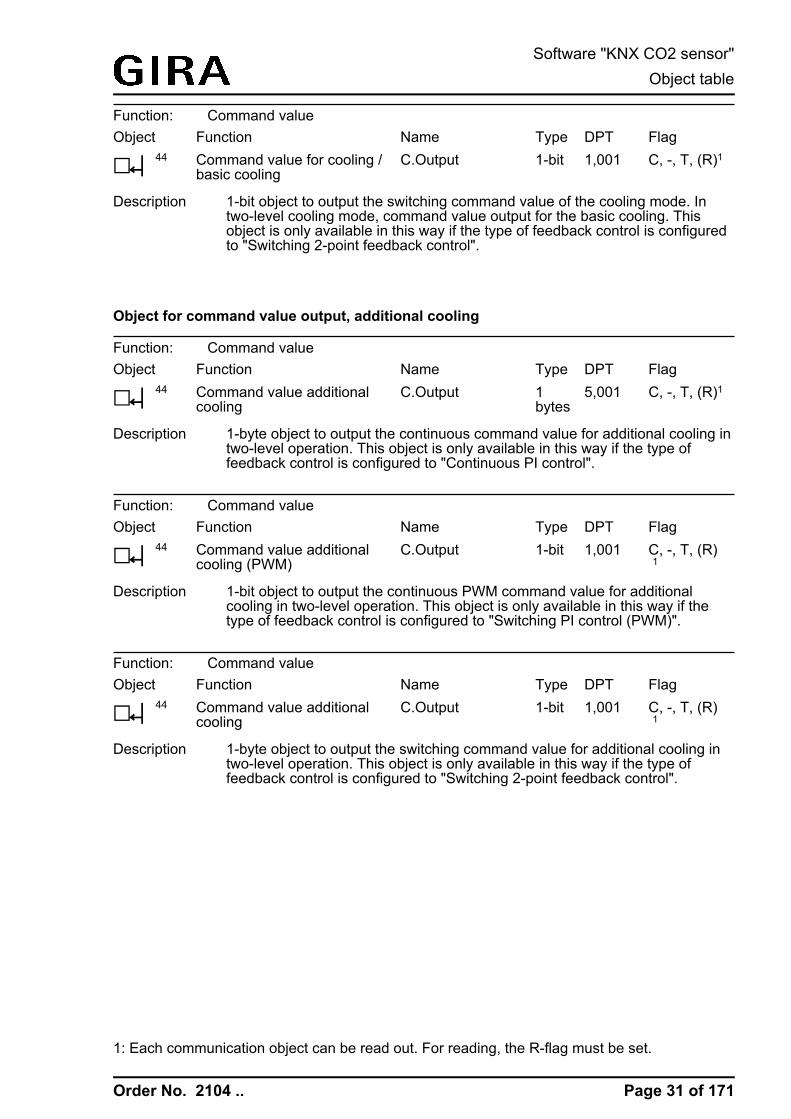
Object for command value output, additional heating and combined valve additionalheating/cooling
Function: Command valueObject
h43
FunctionCommand value additionalheating
NameC.Output
Type1bytes
DPT5,001
FlagC, -, T, (R)1
Description 1-byte object to output the continuous command value for additional heating intwo-level operation. This object is only available in this way if the type offeedback control is configured to "Continuous PI control".
Function: Command valueObject
h43
FunctionCommand value additionalheating (PWM)
NameC.Output
Type1-bit
DPT1,001
FlagC, -, T, (R) 1
Description 1-bit object to output the continuous PWM command value for additionalheating in two-level operation. This object is only available in this way if thetype of feedback control is configured to "Switching PI control (PWM)".
Function: Command valueObject
h43
FunctionCommand value additionalheating
NameC.Output
Type1-bit
DPT1,001
FlagC, -, T, (R) 1
Description 1-byte object to output the switching command value for additional heating intwo-level operation. This object is only available in this way if the type offeedback control is configured to "Switching 2-point feedback control".
Function: Command valueObject
h43
FunctionCommand value additionallevel
NameC.Output
Type1bytes
DPT5,001
FlagC, -, T, (R)1
Description 1-byte object to output the combined continuous command value for additionallevel in two-level operation. This object is only available in this way if thecommand values for heating and cooling mode are output to a shared object(parameter-dependent). The type of feedback control must also be configuredto "Continuous PI control".
1: Each communication object can be read out. For reading, the R-flag must be set.
Page 29 of 171
Software "KNX CO2 sensor"Object table
Order No. 2104 ..
Function: Command valueObject
h43
FunctionCommand value additionallevel (PWM)
NameC.Output
Type1-bit
DPT1,001
FlagC, -, T, (R) 1
Description 1-bit object to output the combined switching PWM command value foradditional level in two-level operation. This object is only available in this wayif the command values for heating and cooling mode are output to a sharedobject (parameter-dependent). The type of feedback control must also beconfigured to "Switching PI control (PWM)".
Function: Command valueObject
h43
FunctionCommand value additionallevel
NameC.Output
Type1-bit
DPT1,001
FlagC, -, T, (R) 1
Description 1-bit object to output the combined switching command value for additionallevel in two-level operation. This object is only available in this way if thecommand values for heating and cooling mode are output to a shared object(parameter-dependent). The type of feedback control must also be configuredto "Switching 2-point feedback control".
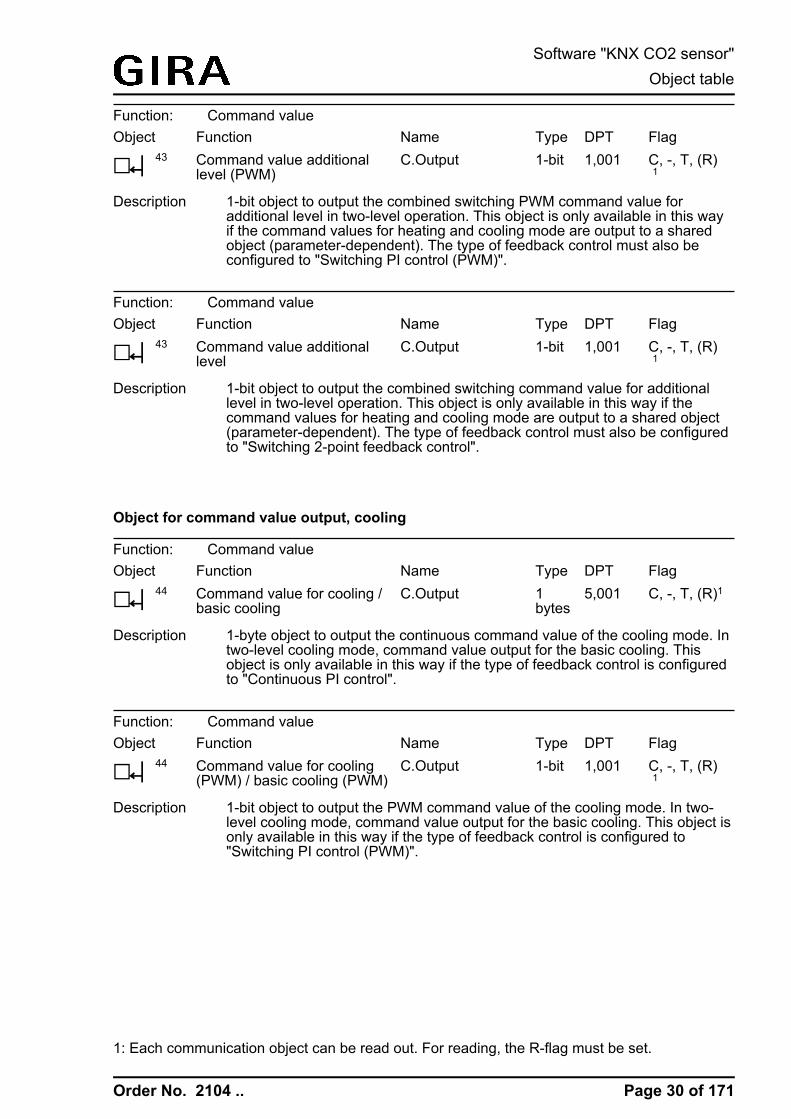
Object for command value output, cooling
Function: Command valueObject
h44
FunctionCommand value for cooling /basic cooling
NameC.Output
Type1bytes
DPT5,001
FlagC, -, T, (R)1
Description 1-byte object to output the continuous command value of the cooling mode. Intwo-level cooling mode, command value output for the basic cooling. Thisobject is only available in this way if the type of feedback control is configuredto "Continuous PI control".
Function: Command valueObject
h44
FunctionCommand value for cooling(PWM) / basic cooling (PWM)
NameC.Output
Type1-bit
DPT1,001
FlagC, -, T, (R) 1
Description 1-bit object to output the PWM command value of the cooling mode. In two-level cooling mode, command value output for the basic cooling. This object isonly available in this way if the type of feedback control is configured to"Switching PI control (PWM)".
1: Each communication object can be read out. For reading, the R-flag must be set.
Page 30 of 171
Software "KNX CO2 sensor"Object table
Order No. 2104 ..
Function: Command valueObject
h44
FunctionCommand value for cooling /basic cooling
NameC.Output
Type1-bit
DPT1,001
FlagC, -, T, (R)1
Description 1-bit object to output the switching command value of the cooling mode. Intwo-level cooling mode, command value output for the basic cooling. Thisobject is only available in this way if the type of feedback control is configuredto "Switching 2-point feedback control".
Object for command value output, additional cooling
Function: Command valueObject
h44
FunctionCommand value additionalcooling
NameC.Output
Type1bytes
DPT5,001
FlagC, -, T, (R)1
Description 1-byte object to output the continuous command value for additional cooling intwo-level operation. This object is only available in this way if the type offeedback control is configured to "Continuous PI control".
Function: Command valueObject
h44
FunctionCommand value additionalcooling (PWM)
NameC.Output
Type1-bit
DPT1,001
FlagC, -, T, (R) 1
Description 1-bit object to output the continuous PWM command value for additionalcooling in two-level operation. This object is only available in this way if thetype of feedback control is configured to "Switching PI control (PWM)".
Function: Command valueObject
h44
FunctionCommand value additionalcooling
NameC.Output
Type1-bit
DPT1,001
FlagC, -, T, (R) 1
Description 1-byte object to output the switching command value for additional cooling intwo-level operation. This object is only available in this way if the type offeedback control is configured to "Switching 2-point feedback control".
1: Each communication object can be read out. For reading, the R-flag must be set.
Page 31 of 171
Software "KNX CO2 sensor"Object table

Order No. 2104 ..
Object for additional PWM heating command value output and combined valve PWMadditional heating/cooling
Function: Command valueObject
h46
FunctionPWM command value forheating / PWM commandvalue, basic heating
NameC.Output
Type1bytes
DPT5,001
FlagC, -, T, (R)1
Description 1-byte object to output the internal continuous command value of a PWMcontroller of the heating mode. In two-level heating mode, command valueoutput for the basic heating. This object is only available in this way if the typeof feedback control is configured to "Switching PI control (PWM)". In additionto the switching 1 bit command value of the PWM, the calculated continuouscommand value of the controller can also be transmitted to the bus anddisplayed, e.g. in a visualisation.
Function: Command valueObject
h46
FunctionPWM command value forheating/cooling / PWMcommand value, basic level
NameC.Output
Type1bytes
DPT5,001
FlagC, -, T, (R)1
Description 1-byte object to output the combined continuous command value of a PWMcontroller of the heating and cooling mode. In two-level heating/cooling mode,command value output for the basic level This object is only available in thisway if the command values for heating and cooling mode are output to ashared object (parameter-dependent). The type of feedback control must alsobe configured to "Switching PI control (PWM)". In addition to the switching 1bit command value of the PWM, the calculated continuous command value ofthe controller can also be transmitted to the bus and displayed, e.g. in avisualisation.
Object for additional command value output, PWM additional heating and combinedvalve PWM additional heating/cooling
Function: Command valueObject
h47
FunctionPWM com. value, add.heating
NameC.Output
Type1bytes
DPT5,001
FlagC, -, T, (R)1
Description 1-byte object to output the internal continuous command value of a PWMcontroller for additional heating in two-level operation. This object is onlyavailable in this way if the type of feedback control is configured to"Continuous PI control". In addition to the switching 1 bit command value ofthe PWM, the calculated continuous command value of the controller can alsobe transmitted to the bus and displayed, e.g. in a visualisation.
1: Each communication object can be read out. For reading, the R-flag must be set.
Page 32 of 171
Software "KNX CO2 sensor"Object table

Order No. 2104 ..
Function: Command valueObject
h47
FunctionPWM command valueadditional level
NameC.Output
Type1bytes
DPT5,001
FlagC, -, T, (R)1
Description 1-byte object to output the combined continuous command value of a PWMfeedback controller for additional level in two-level operation. This object isonly available in this way if the command values for heating and cooling modeare output to a shared object (parameter-dependent). The type of feedbackcontrol must also be configured to "Switching PI control (PWM)". In addition tothe switching 1 bit command value of the PWM, the calculated continuouscommand value of the controller can also be transmitted to the bus anddisplayed, e.g. in a visualisation.
Object for additional command value output, PWM cooling and PWM additional cooling
Function: Command valueObject
h48
FunctionPWM command value forcooling / basic cooling
NameC.Output
Type1bytes
DPT5,001
FlagC, -, T, (R)1
Description 1-byte object to output the internal continuous command value of a PWMfeedback controller of the cooling mode. In two-level cooling mode, commandvalue output for the basic cooling. This object is only available in this way if thetype of feedback control is configured to "Switching PI control (PWM)". Inaddition to the switching 1 bit command value of the PWM, the calculatedcontinuous command value of the controller can also be transmitted to the busand displayed, e.g. in a visualisation.
Function: Command valueObject
h49
FunctionPWM com. value, add.cooling
NameC.Output
Type1bytes
DPT5,001
FlagC, -, T, (R)1
Description 1-byte object to output the internal continuous command value of a PWMfeedback controller for additional cooling in two-level operation. This object isonly available in this way if the type of feedback control is configured to"Switching PI control (PWM)". In addition to the switching 1 bit command valueof the PWM, the calculated continuous command value of the controller canalso be transmitted to the bus and displayed, e.g. in a visualisation.
1: Each communication object can be read out. For reading, the R-flag must be set.
Page 33 of 171
Software "KNX CO2 sensor"Object table

Order No. 2104 ..
Object for setpoint temperature specification
Function: Setpoint temperature specificationObject
h50
FunctionSetpoint temperature
NameC.Input
Type2bytes
DPT9,001
FlagC, -, T, R
Description 2-byte object for external setting of the temperature setpoint. Depending onthe operating mode, the possible range of values is limited by the configuredfrost protection and/or heat protection temperature.The temperature value must always be specified in the format "°C".
Object for basic setpoint shift (only for relative setpoint presetting)
Function: Basic setpoint shiftingObject
h52
FunctionCurrent setpoint shifting
NameC.Output
Type1bytes
DPT6,010
FlagC, -, T, R
Description 1-byte object for giving feedback on the current setpoint shifting. The value ofa counter value in the communication object corresponds to the configuredinterval of the basic setpoint shift. The value "0" means that no shift is active .The value is depicted in a double complement in the positive and negativedirection.This object is only available in this way if relative setpoint presetting isconfigured.
Function: Basic setpoint shiftingObject
h53
FunctionPreset setpoint shifting
NameC.Input
Type1bytes
DPT6,010
FlagC, W, -,(R)1
Description 1-byte object for presetting a basic setpoint shift. The value of a counter valuein the communication object corresponds to the configured interval of thebasic setpoint shift. The value "0" means that no shift is active . The value isdepicted in a double complement in the positive and negative direction.In case the limits of the value range are exceeded by the preset externalvalue, the controller will automatically reset the received value to the minimumand maximum limits.This object is only available in this way if relative setpoint presetting isconfigured.
1: Each communication object can be read out. For reading, the R-flag must be set.
Page 34 of 171
Software "KNX CO2 sensor"Object table

Order No. 2104 ..
Object for outputting the actual-temperature
Function: Actual-temperatureObject
h59
FunctionActual temp. not adjusted
NameC.Output
Type2bytes
DPT9,001
FlagC, -, T, R
Description 2-byte object for following-up the determined and unadjusted roomtemperature value of the internal temperature sensor.The temperature value is always output in the format "°C".
Page 35 of 171
Software "KNX CO2 sensor"Object table

Order No. 2104 ..
4.2.3.3 Object table sensors
General
Function: TemperatureObject
h80
Function Measured value
NameS.Temperature
Type2bytes
DPT9,001
FlagC, -, T, R
Description 2-byte object to output the actual measured value and, if necessary, thecompared measured value of the temperature sensor in the ETS. The objectcan be transmitted if there is a difference between the measured valuesand/or cyclically.
Function: HumidityObject
h81
Function Measured value
NameS.Humidity
Type2bytes
DPT9,007
FlagC, -, T, R
Description 2 byte object for outputting the current measured value of the humidity sensor.The object can be transmitted if there is a difference between the measuredvalues and/or cyclically.
Function: CO2
Object
h82
Function Measured value
NameS.CO2
Type2bytes
DPT9,008
FlagC, -, T, R
Description 2 byte object for outputting the current measured value of the CO2 sensor. Theobject can be transmitted if there is a difference between the measured valuesand/or cyclically.
Function: Dew pointObject
h83
Function Temperature
NameS.Dew point
Type2bytes
DPT9,001
FlagC, -, T, R
Description 2-byte object to output the current, calculated dew point value. The object canbe transmitted if there is a difference between the measured values and/orcyclically.
Limiting values
Function: Limiting valuesObject
h85,88
FunctionLimiting value 1, 2
NameS.Humidity
Type1-bit
DPT1,001
FlagC, -, T, R
Description 1 bit objects for outputting the current limiting values of the humidity sensor.The object can be transmitted if there is a change in value and/or cyclically.Switch-on and switch-off delay is parameterizable.
Page 36 of 171
Software "KNX CO2 sensor"Object table

Order No. 2104 ..
Function: Limiting valuesObject
h86,89,90,91
FunctionLimiting value 1, 2, 3, 4
NameS.CO2
Type1-bit
DPT1,001
FlagC, -, T, R
Description 1 bit objects for outputting the current limiting values of the CO2 sensor. Theobject can be transmitted if there is a change in value and/or cyclically.Switch-on and switch-off delay is parameterizable.
External limiting values
Function: External limiting valuesObject
h93,96
FunctionAbsolute value
NameS.Humidity limitingvalue spec. 1, 2
Type2bytes
DPT9,007
FlagC, W, -,(R)1
Description 2-byte objects for specifying the external limiting values for the humidity by anabsolute value.
Function: External limiting valuesObject
h93,96
FunctionPercentage
NameS.Humidity limitingvalue spec. 1, 2
Type1bytes
DPT5,001
FlagC, W, -,(R)1
Description 1-byte objects for specifying the external limiting values for the humidity by apercentage.
Function: External limiting valuesObject
h93,96
FunctionTeach
NameS.Humidity limitingvalue spec. 1, 2
Type1-bit
DPT1,001
FlagC, W, -,(R)1
Description 1-byte objects for storing the external limiting values for the humidity via aswitching object (teaching)
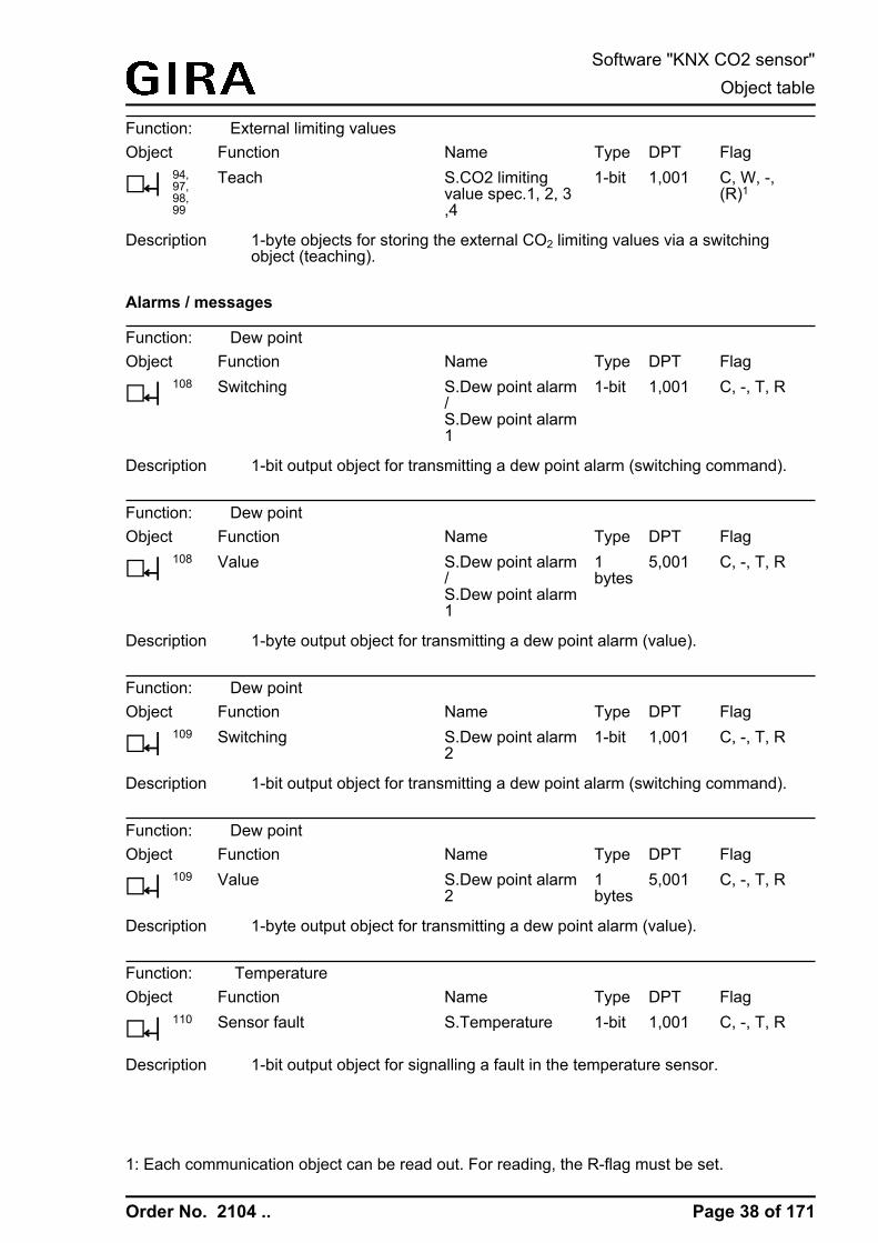
Function: External limiting valuesObject
h94,97,98,99
FunctionAbsolute value
NameS.CO2 limitingvalue spec.1, 2, 3,4
Type2bytes
DPT9,008
FlagC, W, -,(R)1
Description 2-byte objects for specifying the external CO2 limiting values by an absolutevalue.
Function: External limiting valuesObject
h94,97,98,99
FunctionPercentage
NameS.CO2 limitingvalue spec.1, 2, 3,4
Type1bytes
DPT5,001
FlagC, W, -,(R)1
Description 1-byte objects for specifying the external CO2 limiting values by a percentage.
1: Each communication object can be read out. For reading, the R-flag must be set.
Page 37 of 171
Software "KNX CO2 sensor"Object table
Order No. 2104 ..
Function: External limiting valuesObject
h94,97,98,99
FunctionTeach
NameS.CO2 limitingvalue spec.1, 2, 3,4
Type1-bit
DPT1,001
FlagC, W, -,(R)1
Description 1-byte objects for storing the external CO2 limiting values via a switchingobject (teaching).
Alarms / messages
Function: Dew pointObject
h108
FunctionSwitching
NameS.Dew point alarm/S.Dew point alarm1
Type1-bit
DPT1,001
FlagC, -, T, R
Description 1-bit output object for transmitting a dew point alarm (switching command).
Function: Dew pointObject
h108
FunctionValue
NameS.Dew point alarm/S.Dew point alarm1
Type1bytes
DPT5,001
FlagC, -, T, R
Description 1-byte output object for transmitting a dew point alarm (value).
Function: Dew pointObject
h109
FunctionSwitching
NameS.Dew point alarm2
Type1-bit
DPT1,001
FlagC, -, T, R
Description 1-bit output object for transmitting a dew point alarm (switching command).
Function: Dew pointObject
h109
FunctionValue
NameS.Dew point alarm2
Type1bytes
DPT5,001
FlagC, -, T, R
Description 1-byte output object for transmitting a dew point alarm (value).
Function: TemperatureObject
h110
FunctionSensor fault
NameS.Temperature
Type1-bit
DPT1,001
FlagC, -, T, R
Description 1-bit output object for signalling a fault in the temperature sensor.
1: Each communication object can be read out. For reading, the R-flag must be set.
Page 38 of 171
Software "KNX CO2 sensor"Object table

Order No. 2104 ..
Function: HumidityObject
h111
FunctionSensor fault
NameS.Humidity
Type1-bit
DPT1,001
FlagC, -, T, R
Description 1-bit output object for signalling a fault in the humidity sensor.
Function: CO2
Object
h112
FunctionSensor fault
NameS.CO2
Type1-bit
DPT1,001
FlagC, -, T, R
Description 1-bit output object for signalling a fault in the CO2 sensor.
Page 39 of 171
Software "KNX CO2 sensor"Object table

Order No. 2104 ..
4.2.3.4 Object table logic gates
Logic gates
Function: Inputs of the logic gatesObject
h115,116,117,118,121,122,123,124,127,128,129,130,133,134,135,136
FunctionInput /Input 1 - 4
NameL.Logic gate 1 - 4
Type1-bit
DPT1,001
FlagC, W, -,(R)1
Description 1-bit objects for activation of the logical inputs of the logic gates. Dependingon the parameterisation, the inputs can be linked normally inverted 'AND','OR', 'exclusive OR' as well as 'AND with return'.
Function: Outputs of the logic gatesObject
h119,120,125,126,131,132,137,138
FunctionOutput switching /Output 1 - 4 switching
NameL.Logic gate 1 - 4
Type1-bit
DPT1,001
FlagC, -, T, (R)1
Description 1 bit output objects of the logic gates.
Function: Outputs of the logic gatesObject
h119,120,125,126,131,132,137,138
FunctionOutput value /Output 1 - 4 value
NameL.Logic gate 1 - 4
Type1bytes
DPT5,010
FlagC, -, T ,(R)1
Description 1 byte output objects of the logic gates. A value from 0 ... 255 can be assignedto each logic operation result and output.
1: Each communication object can be read out. For reading, the R-flag must be set.
Page 40 of 171
Software "KNX CO2 sensor"Object table

Order No. 2104 ..
4.2.4 Functional description
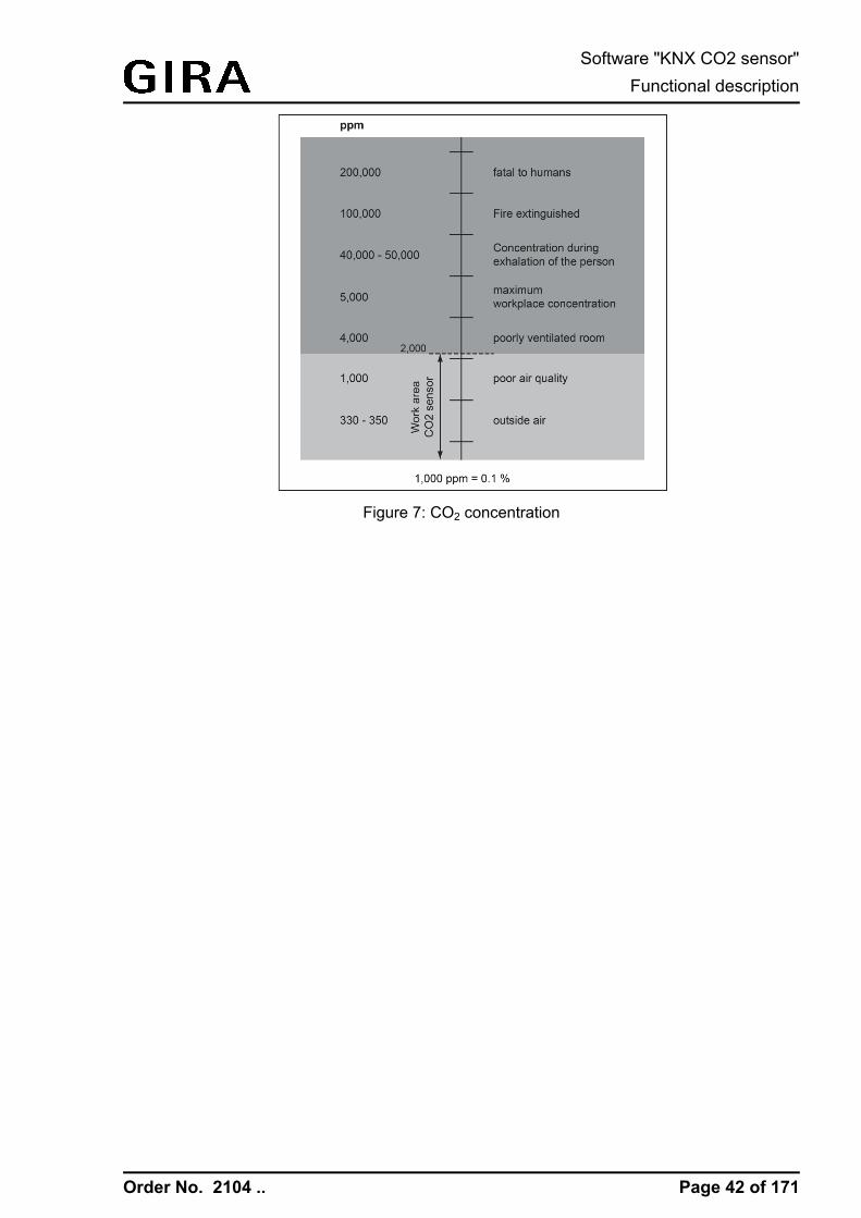
4.2.4.1 Application basicsCombination sensors that measure physical measured values at the installation location areintegrated in the device. In this way, the CO2 content of the ambient air as well as thetemperature and humidity in a room can be measured and the measured values compared aswell. From the measured temperature and air humidity values the dew point can be calculated,which is further processed in the device and can also be transmitted to the bus if necessary.The measured values of the physical sensor are output on the bus via separate communicationobjects. The integrated room temperature controller is operated entirely via communicationobjects. Indicators and controls are not present on the device. Two push-button/switching statescan be read potential-free via both binary inputs, and depending on this, telegrams can betransmitted to the bus.The device is flush mounted in a switchbox and covers the surface of a socket. The device is aso-called monoblock product. It does not require any separate bus coupling or additional powersupply.In rooms frequented by many people, such as conference rooms, meetings or classrooms, theCO2 concentration can increase rapidly. People emit carbon dioxide into the air when theyexhale. The outside air normally inhaled contains about 21 % oxygen and 0.035 % carbondioxide. The exhaled air contains about 16 % oxygen and 4 % carbon dioxide. Even thoughcarbon dioxide first becomes extremely life threatening from a concentration of about 20 %, thewell-being, power of concentration and physical fitness already becomes impaired from 0.08 %,which is first unnoticeable for the person affected, however.Hence, various standards recommend a maximum value of 0.1 % carbon dioxide in the roomair. In view of today's construction standard and high air tightness of the building shell, thisvalue is very often exceeded. The result: as from a ratio of 1,000 ppm (0.1%), people becometired, lack concentration and subsequently complain of a headache. In the case of higherconcentrations, increased heart beat, shortness of breath and unconsciousness occur (the so-called CO2 anaesthesia). CO2 concentrations of 8 percent and more can cause death within 30to 60 minutes.
Automatic monitoring of the air quality and automatically controlled ventilation can prevent thiseffect. The work area of the CO2 sensor is between 0% and 0.2% because rooms with theseCO2 concentrations should already be ventilated (Figure 7).
Page 41 of 171
Software "KNX CO2 sensor"Functional description
Order No. 2104 ..
Figure 7: CO2 concentration
Page 42 of 171
Software "KNX CO2 sensor"Functional description

Order No. 2104 ..
4.2.4.2 Push button interface
4.2.4.2.1 IntroductionThe device incorporates the function of a 2-gang push-button interface, i.e. it has twoindependent binary inputs. The push-button interface permits up to two potential-free push-button/switching states with common reference potential to be read and evaluated. The deviceis fitted with a 3-pin device connection terminal strip for the binary inputs.It is possible to specify separately for each input whether and which reactions should take placeon signal edges and after bus voltage return. This means that a defined telegram can betransmitted to the bus according to the input signal or with forced control. The configured "Delayafter reset or bus voltage return" must first have elapsed before the pre-set reaction is executed.Within the delay, any pending edges or signals at the inputs are not evaluated and arediscarded. The delay time is configured generally for all the inputs.It is also possible to configure a general telegram rate limit. In this case, no telegram istransmitted within the first 17 s after bus voltage return.It should be noted that the configured "Delay after reset or bus voltage return" is also activeduring this time and the configured behaviour is not executed after bus voltage return if thedelay time elapses within the first 17 seconds.The telegram rate limit is configurable globally for all inputs. The telegram rate limit has noinfluence on the telegrams of the room temperature controller function, sensor measuredvalues, limiting values or logic gates.
Page 43 of 171
Software "KNX CO2 sensor"Functional description

Order No. 2104 ..
4.2.4.2.2 Function "no function"If the function of an output is configured to "No function", the device deactivates the inputchannel completely. Consequently, all respective communication objects are hidden in the ETS.
Page 44 of 171
Software "KNX CO2 sensor"Functional description

Order No. 2104 ..
4.2.4.2.3 "Switching" functionIf the function of the input is configured to "Switching", the parameters "Command on risingedge" and "Command on falling edge" are visible for two separate switching objects.The selectable switching commands are "OFF", "ON" or "TOGGLE". "TOGGLE" will switch andtransmit the value, which is stored in the switching object. In addition, the transmission of aswitching command may be suppressed (setting "no reaction").Optionally, cyclical transmission can be activated by the parameter of the same name. Theinternally or externally tracked object value in the switching objects is always transmitted. Theobject value is then also transmitted cyclically when "no reaction" is assigned to a rising orfalling edge.Cyclical transmission always occurs immediately after bus voltage return if the configured valueof the telegram after bus voltage return corresponds to the object value configuration for cyclicaltransmission. If telegram rate limit is enabled, the cyclical transmission occurs after 17 secondsat the earliest.During an active disable, no cyclical transmissions take place via the disabled input.
Page 45 of 171
Software "KNX CO2 sensor"Functional description

Order No. 2104 ..
4.2.4.2.4 "Dimming" functionIf the function of the input is configured to "Dimming", various parameters for the dimmingfunction and the "Switching" and "Dimming" objects are visible.The "Operation" parameter determines whether this channel ("single-area operation") alone isused or in conjunction with the another channel ("dual-area operation"). The switching ordimming commands, which should be transmitted to the bus in the case of a positive signaledge, are also defined here. The executable commands are "Darker (OFF)", "Brighter (ON)" or"TOGGLE".In the "Darker (OFF)" setting, an OFF telegram is triggered in the case of a short signal edge,and a dimming telegram (darker) is triggered in the case of a long signal edge.In the "Brighter (ON)" setting, an ON telegram is triggered in the case of a short signal edge,and a dimming telegram (brighter) is triggered in the case of a long signal edge.In the "TOGGLE" setting, the switching state stored internally in the switching object is toggledin the case of a short signal edge.In addition, the dimming step width can be adjusted for "increasing and decreasing brightness"and the "time between switching and dimming ". A "stop telegram" can also be released at theend of the dimming operation (telegram transmission on releasing the button).If the parameter "telegram repetition" is set to "Yes", dimming telegrams can be transmittedcyclically during an active signal edge. The "time between two dimming telegrams" isadjustable. In each case this time has elapsed, a new dimming telegram is issued with theparameterized dimming step width.
Page 46 of 171
Software "KNX CO2 sensor"Functional description

Order No. 2104 ..
4.2.4.2.5 "Venetian blind" functionIf the function of the input is configured to "Venetian blind", various parameters for the Venetianblind function and the "Short time operation" and "Long-time operation" objects are visible. The"operation concept" parameter predefines the telegram sequence for short and long-timetelegrams that are transmitted with or during button actuation.For controlling the Venetian blind, shutter or awning operations the push button interface issupported by two operation concepts, in which the telegrams are transmitted with a differenttime sequence. Therefore a wide variety of drive configurations can be operate. The differentoperation concepts are described in detail in the following chapters.
Operation concept "short – long – short"In the operation concept "short – long – short", the input shows the following behaviour...- Immediately after a rising edge the device transmits a short time telegram. Pressing the
button stops a running drive and starts time T1 ("time between short time and long timecommand"). No other telegram will be transmitted, if the key is released within T1. Thisshort time serves the purpose of stopping a continuous movement. The "time betweenshort and long time command" should be selected shorter than the short time operation ofthe actuator to prevent a jerky movement of the blind.
- If the button is kept depressed longer than T1, the device transmits a long time telegramafter the end of T1 for starting up the drive and time T2 ("slat adjusting time") is started.
- If a falling edge is detected within the slat adjustment time, the device transmits anadditional short time telegram. This function is used for adjusting the slats of a blind. Thefunction permits stopping the slats in any position during their rotation. The "slat adjustingtime" should be chosen as required by the drive for a complete rotation of the slats.
- If the "slat adjusting time" is selected longer than the complete travelling time of the drive, apushbutton function is possible as well. In this case, the driver only remains on while thebutton is kept depressed at the input. If the button is kept depressed longer than T2, thedevice transmits no further telegram. The drive remains on until the end position isreached.
Figure 8: Operation concept "short – long – short"
Operation concept "long – short":In the operation concept "long – short", the input shows the following behaviour...- Immediately after a rising edge the device transmits a long time telegram. The drive begins
to move and time T1 ("slat adjusting time") is started.- If a falling edge is detected within the slat adjustment time, the device transmits a short
time telegram. This function is used for adjusting the slats of a blind. The function permitsstopping the slats in any position during their rotation.The "slat adjusting time" should be chosen as required by the drive for a complete rotationof the slats. If the "slat adjusting time" is selected longer than the complete travelling time ofthe drive, a pushbutton function is possible as well. In this case, the driver only remains onwhile the button is kept depressed at the input.
- If the button is kept depressed longer than T1, the device transmits no further telegram.The drive remains on until the end position is reached.
Page 47 of 171
Software "KNX CO2 sensor"Functional description

Order No. 2104 ..
Figure 9: Operation concept "long – short"
The parameter "Command on rising edge" specifies which polarity the telegrams have for longor short-time operation. The executable commands are "UP", "DOWN" or "TOGGLE".
Page 48 of 171
Software "KNX CO2 sensor"Functional description

Order No. 2104 ..
4.2.4.2.6 Function"Value transmitter 1 byte / 2 byte"
For each input whose function is set to "Value transmitter", the ETS indicates either a 1-byte ora 2-byte object. The data format of the value object is dependent on the set function of the valuetransmitter. The "Function as" defines the function on one of the following value transmitterapplications...- Dimming value transmitter (1-byte),- Temperature value transmitter (2-byte),- Brightness value transmitter (2-byte),- Light scene extension without memory function (1-byte),- Light scene extension with memory function (1-byte).
The dimming value transmitter, temperature and brightness value transmitter different in dataformat and in the range of values. The independent function of the light scene extension isspecial and is described (see page 51).
Dimming value transmitter, temperature and brightness value transmitterIn the function as a dimming value transmitter, the input can transmitted unformatted integers inthe range 0 ... 255 to the bus. As a brightness value transmitter, the input transmits formattedfloating point values in the range 0 … 1500 Lux and, as a temperature value transmitter, in therange 0 … 40 °C. Table 1 shows a summary of the value ranges of the value encoders. Thevalues to be transmitted are configured in the ETS and can be adjusted later during deviceoperation (see value adjustment below).The edge evaluation of the device means that it can transmit values only on a rising edge, onlyon a falling edge or on a rising and falling edge. In this way, it is possible to make adjustmentsto the contact connected at the input (push-button as NC contact or NO contact and switch).
Value transmitter type Function Lower numericallimit
Upper numericallimit
Dimming value transmitter 0 ... 255 0 255
Temperature valuetransmitter
Temperaturevalue
0 °C 40 °C
Brightness value transmitter Brightness value 0 lux 1.500 lux
Table 1: Value ranges of dimming value transmitter, temperature and brightness valuetransmitter
Value adjustment for dimming value transmitter, temperature and brightness value transmitterIn the dimming value transmitter and temperature and brightness value transmitter, anadjustment of the value to be transmitted during device operation can be configured. A valueadjustment can only be configurable in the ETS when the value is to be transmitted only on arising edge or only on a falling edge, i.e. a push-button is connected to the input.A value adjustment is introduced by a long signal at the input (> 5 s) and continues for as longas the signal is detected as active, i.e. the push-button is actuated. With the first adjustmentafter commissioning, the value programmed by the ETS is increased cyclically by the step widthconfigured for the dimming value transmitter and transmitted. The step width of thetemperature value transmitter (1K) and the brightness value transmitter (50 Lux) is permanentlydefined. The previously transmitted value is saved after releasing the pushbutton. The next longpushbutton actuation adjusts the saved value and the direction of the value adjustmentchanges.The time between two telegrams on adjusting values can be configured in the ETS.
Example of value adjustment (Figure 10):- Function as dimming value transmitter
Page 49 of 171
Software "KNX CO2 sensor"Functional description

Order No. 2104 ..
- Transmit value on = Rising edge- Value configured in the ETS for rising edge = 17- Step width = 5
Figure 10: Example to change the value for dimming value transmitter
i There is no value over- or underrun on adjustment. If, during an adjustment, the maximumor minimum value is reached (see Table 1), no more telegrams are transmitted.
i To ensure that, during a value adjustment, for example the controlled lighting switches offor switches on at the maximum, the limit values (e.g. the values "0" or "255") are alwaystransmitted when the limits of the adjustable range are reached. This also takes placewhen the configured step width of these values is not immediately taken into account (seeexample above: step width = 5; value "2" is transmitted, then value "0").In this case, to ensure that the original starting value can be reset on resetting with achange to the adjustment direction, the first value jump is not equal to the preset step width(see example above: step width = 5; value "0" is transmitted, then values "2"; "7" etc.).
i The newly adjusted values are stored in RAM. After a device reset (bus voltage failure orETS programming operation), the adjusted values are replaced by the values originallyconfigured in the ETS.
Page 50 of 171
Software "KNX CO2 sensor"Functional description

Order No. 2104 ..
4.2.4.2.7 Function "Light scene extension with/without memory function"With a configuration as a light scene extension without a memory function, it is possible to recalla light scene. With a rising, falling or rising and falling edge, the light scene number configuredin the ETS is immediately transmitted to the bus.
With a configuration as a light scene extension with a memory function, it is possible to generatea memory telegram according to the light scene to be transmitted. For this, the appropriatememory telegram is transmitted for a long signal according to the configured edge evaluation(push-button as NC contact or NO contact - not as switch!). In this case, the time for longactuation can be configured (but not to below 5 s). With short actuation < 1 s, the configuredlight scene number (without memory telegram) is transmitted. If the actuation last longer than1 s but less than 5 s, no telegram is triggered.In addition, there is the option of only transmitting a memory telegram without prior light scenerecall. In this case, the parameter "Only memory function ?" must be set to "Yes".
Examples for a light scene extension with memory function
1.) Only memory function = No
2.) Only memory function = Yes
Figure 11: Example of scene storage
"Only memory function = No":If a rising or falling edge is detected at the input (according to the configuration), the timerecording operation begins. If actuation ceases during the first second, the appropriate lightscene recall takes place immediately. If the signal length is longer, then the memory telegram istransmitted after 5 s.
"Only memory function = Yes":The memory telegram is transmitted immediately after detection of the appropriate signal edge.
Page 51 of 171
Software "KNX CO2 sensor"Functional description

Order No. 2104 ..
4.2.4.2.8 Response to bus voltage returnIt is possible to specify separately for each input whether or which reaction should take placeafter bus voltage return. This means that a defined telegram can be transmitted to the busaccording to the input signal or with forced control.The configured "Delay after reset or bus voltage return" must first have elapsed before the pre-set reaction is executed!Within the delay, any pending edges or signals at the inputs are not evaluated and arediscarded. The delay time is configured generally for all the inputs.
A general telegram rate limit is configurable. In this case, no telegram is transmitted within thefirst 17 s after bus voltage return.It should be noted that the configured "Delay after bus voltage return" is also active during thistime and the configured behaviour is not executed after bus voltage return if the delay timeelapses within the first 17 seconds!
i The communication objects of the room temperature controller function, sensor, limitingvalues and logic gates are independent of the configured delay time.
i The option "transmit current input state" of the button functions "switching" and "valuetransmitter" for the behaviour after bus voltage return evaluates an open switching contactas a falling edge and a closed switching contact as a rising edge. The current input state ofthe input is transmitted according to the configuration for the rising or falling edge.
Page 52 of 171
Software "KNX CO2 sensor"Functional description

Order No. 2104 ..
4.2.4.2.9 Disabling function of the InputsA specific reaction can be executed independently for each input at the beginning and end of adisable.In so doing, it is possible to configure to "No reaction". Only in this case are dimming or venetianblind control operations or value adjustments completed during an active disable. In all othercases, the configured command is transmitted instantly at the beginning of the disable.Furthermore, edges or signals on the corresponding inputs are not evaluated during an activedisable! Updates on disabling objects (disable or enable) cause the transmission every time ofthe corresponding configured command "at the beginning or end of the disable".
i For "switching" function: During an active disable, no cyclical transmissions take place viathe disabled input. If a cyclical transmission took place prior to activating the disablingfunction, no cyclical transmission will take place any more at the end of the disable in theconfiguration "no reaction". In this case, the object value is first transmitted cyclically againafter an update on the switching object. In all other cases, the object value is transmittedcyclically again after the end of the disable.
Page 53 of 171
Software "KNX CO2 sensor"Functional description

Order No. 2104 ..
4.2.4.3 Sensor function
4.2.4.3.1 Temperature sensor
Basic principlesThe temperature sensor of the device measures the actual temperature of the room cyclically.The measured value can be transmitted instantly to the bus via a separate 2-byte object, andthus be made available to KNX display components. The temperature sensor is also used forthe integrated room temperature controller for measuring the room temperature. The controlalgorithm calculates the adjusted command value from the difference between actual andsetpoint temperatures.Further information concerning the room temperature measurement of the controller can belooked up in the corresponding chapter of this product documentation (see page 99).
The temperature sensor is integrated in the room temperature controller. Alternatively (e.g. if theroom temperature controller has been installed in an unfavourable location or operates indifficult conditions, for example, in a moist atmosphere) or in addition (e.g. in large rooms orhalls), a second temperature sensor linked via bus telegrams can be used to determine theactual value. This second sensor can either be a room temperature controller coupled via theKNX or a controller extension with temperature detection.
Installation locationWhen choosing the installation location of the controller or the external sensor, the followingpoints should be considered...- The temperature sensor should not be used in multiple combinations, especially together
with flush-mounted dimmers.- Do not install the temperature sensor in the area of large electrical consumers (avoid heat
influences).- The push button sensor should not be installed in the vicinity of radiators or cooling
systems.- The temperature sensor should not be exposed to direct sun.- The installation of sensors on the inside of an outside wall might have a negative impact on
the temperature measurement.- Temperature sensors should be installed at least 30 cm away from doors, windows or
ventilation units and at least 1.5 m above the floor.i Since all parameters are oriented by the room temperature measured by the temperature
sensor, the exact temperature measurement is an essential component of the roomtemperature controller.
i Room temperature measurement by the device is always active, irrespective of the "Roomtemperature control" function and can thus be used independently (e.g. for simplemeasurement and display of a room temperature without control).
Behaviour in case of sensor faultsThe device monitors the integrated, digital, combination sensors cyclically. If communication ispermanently impaired (e.g. due to a sensor or device fault), the corresponding alarm object"sensor fault" is written with the value "ON" for the error message and a telegram is transmittedto the bus.The sensor is deactivated by the device during a fault. Afterwards, an attempt is made tocyclically reactivate the sensor. If this is achieved reliably after a certain amount of time, thedevice resumes measuring the physical values and also resets the sensor fault message by an"OFF" telegram. In case of an impaired and deactivated sensor, the value "0" is output asmeasured value.
i After a device reset (programming with the ETS, bus voltage return) the objects "sensorfault" are updated according to the current state and telegrams are transmitted to the bus.
Page 54 of 171
Software "KNX CO2 sensor"Functional description
Order No. 2104 ..
4.2.4.3.2 Humidity sensor
GeneralA combination sensor, which enables a measurement of the relative air humidity, is integrated inthe device. The measured value can be transmitted instantly to the bus via a separate 2-byteobject, and thus be made available to KNX display components. The measured value is alsoused for calculating the dew point.- Measuring range... 10 ... 95 % rel. humidity- Work area... 0 ... 95 % (non-condensing)
Humidity measurementThe humidity sensor measures the humidity in the room cyclically, which serves to improve theindoor climate. A relative air humidity between 40% and 60% is recommended as a comfortrange for offices and working areas.
To ensure that an accurate value is constantly determined for the relative humidity, it is veryimportant to also measure the exact temperature of the room air in addition to the humidityvalue. For this purpose, the determined room temperature value, and if necessary, the roomtemperature value adjusted by ETS parameters is used, whereby the self-heating of the sensoris compensated among other things.
Furthermore, the value of the relative air humidity is necessary for calculating the dew point.With the aid of the dew point and dew point alarms, the condensation of humidity can beprevented on cold thermal bridges.
Dew pointThe dew point temperature is calculated by the device on the basis of the determined roomtemperature. Digital sensors as used in this device, for example, provide the basis for this. Thedetermined humidity value of the sensor is adjusted by means of the Magnus formula which isan approximation formula for calculating the saturated vapour pressure depending on thetemperature. It is very accurate (< 0.22 %) in the range between 0°C and 100°C and is primarilyused in meteorology and building physics for determining the dew point.Before reaching the dew point temperature, an alarm object can be switched, which activatesthe room ventilation, for example. The temperature difference before reaching the dew pointtemperature, i.e. the alarm threshold, is set via the parameter "Lead dew point alarm". Theswitch-off hysteresis defines the temperature value below the alarm threshold at which point thedew point alarm is deactivated again.It is possible to select whether one or two alarm objects should be used. The data format of thealarm object can be selected between 1-bit and 1-byte.
Behaviour in case of sensor faultsThe device monitors the integrated, digital, combination sensors cyclically. If communication ispermanently impaired (e.g. due to a sensor or device fault), the corresponding alarm object"sensor fault" is written with the value "ON" for the error message and a telegram is transmittedto the bus.The sensor is deactivated by the device during a fault. Afterwards, an attempt is made tocyclically reactivate the sensor. If this is achieved reliably after a certain amount of time, thedevice resumes measuring the physical values and also resets the sensor fault message by an"OFF" telegram. In case of an impaired and deactivated sensor, the value "0" is output asmeasured value.
i After a device reset (programming with the ETS, bus voltage return) the objects "sensorfault" are updated according to the current state and telegrams are transmitted to the bus.
Page 55 of 171
Software "KNX CO2 sensor"Functional description

Order No. 2104 ..
4.2.4.3.3 CO2 sensorGeneralA CO2 sensor can be useful in all cases where CO2 develops in enclosed spaces. In somecountries, a CO2 sensor is already compulsory in schools. This CO2 sensor is designed exactlyfor this purpose and can also be used for controlling automatic room ventilation available onsite.The power supply of the CO2 sensor is supplied via the bus.
Functional descriptionAfter connecting the bus voltage of after bus voltage return, the CO2 sensor starts measuringthe CO2 concentration of the room air. The measured values are transmitted to the bus. Ifadjustable limiting values are exceeded within the range from 0...2000 ppm, specific actions canbe triggered (e.g. room ventilation). The 4 limiting values are preset as follows: 400 ppm for verygood air quality, 800 ppm for good air quality, 1,200 ppm for medium air quality and 1,600 ppmfor poor air quality.
CO2 sensor moduleThe integrated CO2 sensor module is responsible for measuring the CO2. It is maintenance-freedue to the automatic calibration method (dual beam measuring cell). It has excellent long-termstability.
i After switch-on, the CO2 sensor module requires a warm-up period of up to 5 minutes, untilnormal operation is reached.The automatic calibration method is only available in the case of permanent bus voltageand after 24 hours for the first time.
Sensor data of the CO2 sensor module- Measuring range... 0..2000 ppm- Accuracy (when 25 °C and 1013 mbar)... <± 50 ppm (+2% of the measured value)- Temperature dependency... typ. 2 ppm / K (0 ... 50 °C)- Response time... <5 min
Air pressureThe measured value of the CO2 sensor is air pressure dependent. As the air pressureincreases, so does the measured value. The parameter "Height of location above sea level" isprovided in order to compensate for this dependency. The current height of the location (inmeters above sea level) can be parameterised using this parameter. The installation height isadjusted in 1m increments.
Page 56 of 171
Software "KNX CO2 sensor"Functional description

Order No. 2104 ..
Figure 12: Pressure increase depending on the height of location
Behaviour in case of sensor faultsThe device monitors the integrated, digital, combination sensors cyclically. If communication ispermanently impaired (e.g. due to a sensor or device fault), the corresponding alarm object"sensor fault" is written with the value "ON" for the error message and a telegram is transmittedto the bus.In the case of a fault, the CO2 sensor is deactivated permanently by the device for safetyreasons. In case of an impaired and deactivated sensor, the value "0" is output as measuredvalue.
i After a device reset (ETS programming operation or bus voltage return), the CO2 sensor isrestarted again. If there is no fault anymore, the device resumes measuring the CO2concentration of the room air and updates the object "Sensor fault" with "OFF". Should thesensor still be impaired after a reset, the device deactivates the sensor and transmits thevalue "ON" to the bus via the alarm object "Sensor fault".
Page 57 of 171
Software "KNX CO2 sensor"Functional description

Order No. 2104 ..
4.2.4.3.4 Limiting valuesFour limiting values can be assigned to the CO2 measured value and two limiting values to thehumidity measured value. This makes it possible to trigger actions when the adjustable limitsare exceeded or undershot. Thus, if there is a certain CO2 content in the room air, for example,ventilation can be activated or warning messages generated.
Types of limiting value specification
The value of a limiting value itself can be specified in three ways.- Limiting value specification via the parametrization.
This is the value configured in the ETS, which comes into effect after the initialisation orafter a download. This value can be overwritten via an external object or the teachingfunction. In this case, the internal value is first reactivated after downloading the projectonce again.
- Limiting value specification via an external object.This external value overwrites permanently the value of the limiting value specification viathe parametrization. In this case, the internal value is first reactivated after downloading theproject once again.
- Limiting value specification via the teaching function.This function makes it possible to define the current measured value as the limiting valueby pressing an external push-button sensor. This value overwrites permanently the value ofthe limiting value specification via the parametrization. In this case, the internal value is firstreactivated after downloading the project once again.
i If the internal value of the limiting value specification is overwritten by parameterization atany point, this value will remain lost until a new download is performed via the ETS.
Setting limiting value specification via parametrizationThe limiting value specification for the measured values "CO2" and "Humidity" are set by meansof the parameters "Limiting value X" in the parameter node "Limiting value X"."n limiting values active" is set for the measured value on the parameter page "CO2measurement" or "humidity measurement". There is a maximum of four (n = 1…4) limitingvalues available for the CO2 measured value, and a maximum of two (n = 1…2) for the humiditymeasured value.o Enter the required value in the input field "Limiting value X".i This value is loaded to the device during initialization and renewed download.i The set value is retained until it is overwritten by an external value.
Hysteresis of the limiting valuesThe device has four limiting values for the CO2 measured value, and two limiting values for thehumidity measured value. Each limiting value has an adjustable hysteresis and a definition ofthe response when the value is exceeded or undershot. The hysteresis itself serves to preventfrequent switching backwards and forwards when there is a measured value in the approximatearea of the limiting value. This, for example, prevents a fan from constantly being switched onand off. The hysteresis values should therefore be chosen as large as possible. Thesecircumstances are explained in the following diagrams.
Page 58 of 171
Software "KNX CO2 sensor"Functional description

Order No. 2104 ..
Figure 13: Frequency of switching without hysteresis
One can see here that when no hysteresis is incorporated the limiting value object changes itsstate each time the value is undershot or exceeded. This is different if you parameterise achange of state from '1' to '0' only when the limit value is undershot by the measured valueminus hysteresis.
Figure 14: Frequency of switching with hysteresis parameterised.
Page 59 of 171
Software "KNX CO2 sensor"Functional description

Order No. 2104 ..
i The hysteresis must be selected in such a way that the start of the measurement range isnot reached or undershot and the end value is not reached or exceeded, as otherwise achange of state can only occur once and not any more until a reinitialisation.
Setting the hysteresis of the limiting valueThe hysteresis of the limiting values for the measured values "CO2" and "Humidity" is set bymeans of the parameters "Limiting value X" in the parameter node "Limiting value X"."n limiting values active" is set for the measured value on the parameter page "CO2measurement" or "humidity measurement". There is a maximum of four (n = 1…4) limitingvalues available for the CO2 measured value, and a maximum of two (n = 1…2) for the humiditymeasured value.o Enter the appropriate value in the input field "Hysteresis".
The hysteresis is set.
Response of the limiting value object when the limiting value is exceeded and undershotFor the parameter "Activation limiting value X" in the parameter node "Limiting value X" adirection-dependent setting is made for how the limiting value responds when the set limitingvalue is exceeded or undershot. If, for example, "undersh. LV=ON, exceed LV+Hyst.=OFF" isselected, the limiting value object is then set to "1" if the limiting value is undershot, and thelimiting value object will first be set to "0" when the limiting value plus hysteresis is exceeded.
Figure 15: Activation of limiting value
If for a cycle, "no telegr.", i.e. no telegram is configured, the cyclical transmission of the limitingvalue X is also prevented when this function is activated. The cyclical transmission of thelimiting value remains interrupted until the opposite state is reached once again.Example: Undersh. is configured LV=ON, exceed LV+hyst.=no telegr.- An ON telegram is sent when the limiting value is undershot. If "Cycl. sending of limiting valueX" is parametrized with '10', then this ON telegram is additionally sent every 100 seconds (10s x10).
Page 60 of 171
Software "KNX CO2 sensor"Functional description

Order No. 2104 ..
- If the limiting value plus hysteresis is undershot, no telegram is transmitted and the cyclicaltransmission is suppressed, too.- If the limiting value is undershot again, an ON telegram is transmitted in turn and the cyclicaltransmission of this ON telegram is reactivated, too.
Specifying limiting values via external objectsIf the limiting values are to be adjustable and thus dynamically adaptable while the system isrunning, then the parameter "External limiting value X" in the parameter node "limiting value X"can be set to "Absolute value via 2-byte object" or "Percentage via 1-byte object". Thecommunication objects "S... Limiting value specification - Absolute value" (2-byte) or "S...Limiting value specification - percentage" (1-byte) can, for instance, be linked to the valuetransmitter objects of an external push-button.i If the value specification is triggered by a push-button sensor, this push-button sensor
should be configured in such a way that it first transmits the configured value after a longbutton-press (more than 3 seconds) in order to prevent operating errors.
Limiting value specification via teaching functionIf the user should have the option to use the current measured value as a new limiting valuewithout knowing the numerical value himself, the parameter "External limiting value X" in theparameter node "Limiting value X" can be set to "Store limiting value via switching object(teaching)". Once the object "S... Limiting value specification - Learning" thus receives atelegram with the value "1", the device applies the last measured value as new limiting value.Telegrams with the value "0" are ignored.i If the Teaching function is triggered by a push-button sensor, this push-button sensor
should be configured in such a way that it first transmits the value "1" after a long button-press (more than 3 seconds) in order to prevent operating errors.
Setting limiting value specification via external objects or by means of teachingLimiting value specification via an external object for the measured values "CO2" and "Humidity"is set by means of the parameter "External limiting value X" on parameter node "Limiting valueX"."n limiting values active" is set for the measured value on the parameter page "CO2measurement" or "humidity measurement". There is a maximum of four (n = 1…4) limitingvalues available for the CO2 measured value, and a maximum of two (n = 1…2) for the humiditymeasured value.o In the input field "External limiting value X", select from the list whether the limiting value
specification should be set by "Absolute value via 2-byte object", by "Percentage via 1-byteobject" or by "Teaching".
i The set value overwrites the limiting value specification via parametrization until it isoverwritten by another external value.
i The externally predefined value is overwritten by the value configured in the ETS during anETS programming operation.
Switch-on and switch-off delay of the limiting valuesAll limiting values of the device can be given switch-on and switch-off delays. It should be notedhere that not only is the transmission affected on change of this delay, but the cyclicaltransmission of the limiting value object, too.
Page 61 of 171
Software "KNX CO2 sensor"Functional description

Order No. 2104 ..
Figure 16: Block diagram for switch-on and switch-off delay
(10) Measured value(11) Limiting value and hysteresis processing(12) Internal limiting value(13) ON delay and OFF delay(14) Delayed, internal limiting value(15) Processing of cyclic sending, sending when change, activation of limiting value(16) Limiting value object
When the value of an internal limiting value (12) changes from "0" to "1", the parameter value ofthe switch-on delay is evaluated. When the value of an internal limiting value changes from "1"to "0", the parameter value of the switch-off delay is evaluated. If "no delay" is set, then thevalue of the delayed internal limiting value immediately takes the value of the internal limitingvalue. When a delay time is set, a timer with the delay time (13) is loaded and started. Onlywhen it expires is the value of the internal limiting value accepted as the value for the delayedinternal limiting value (14) and the limiting value sent in accordance with the parameterisation.The cyclic sending is also affected by this delay. If the internal limiting value changes before thetimer expires, then it is stopped and the limiting value remains unchanged. Consequently, nolimiting value telegram, triggered by the parameter "Transmission on change of the limitingvalue object", is transmitted either.
Setting the switch-on delayA switch-on delay can be set for all limiting values by means of the parameter "Switch-on delayinternal limiting value object"."n limiting values active" is set for the measured value on the parameter page "CO2measurement" or "humidity measurement".o In the parameter ""Switch-on delay for internal limiting value object", select the appropriate
value from the list.The switch-on delay is set.
Setting the switch-off delayAn internal switch-off delay can be set for all limiting values by means of the parameter "Switch-off delay for internal limiting value object"."n limiting values active" is set for the measured value on the parameter page "CO2measurement" or "humidity measurement".o In the parameter "Switch-off delay for internal limiting value object", select the appropriate
value from the list.The switch-off delay is set.
Page 62 of 171
Software "KNX CO2 sensor"Functional description

Order No. 2104 ..
Setting sending of a limiting value when there is a changeThe transmission property of the limiting values can be influenced by means of the parameter"Transmission on change of the limiting value object" in the parameter node "Limiting value X"."n limiting values active" is set for the measured value on the parameter page "CO2measurement" or "humidity measurement". There is a maximum of four (n = 1…4) limitingvalues available for the CO2 measured value, and a maximum of two (n = 1…2) for the humiditymeasured value.o Set the parameter "Transmission on change of the limiting value object" to "Yes".
The value is transmitted on a change of state from "0" to "1" or from "1" to "0".i The object value is sent again if the limiting value even occurs again, even if the reversed
event is is parametrized to "No telegr."
Cyclic sending of the limiting valuesAll limiting value objects of the sensors can transmit their state cyclically to the bus.i Telegrams of limiting value objects generated by the automatic transmission
("Transmission on change of the limiting value object") do not influence the cycle time forthe cyclical transmission of the limiting value objects.
i If a combination with "no telegr." is set during activation of the limiting value, thecorresponding object value is not transmitted on change nor cyclically via the limiting valueobject.
Setting cyclical transmission of a limit value"n limiting values active" is set for the measured value on the parameter page "CO2measurement" or "humidity measurement". There is a maximum of four (n = 1…4) limitingvalues available for the CO2 measured value, and a maximum of two (n = 1…2) for the humiditymeasured value.o Set the parameter "Cyclical transmission of the limiting value object" to the required cycle
time.The limiting value is sent at the set interval.
i If the setting is "0", the limiting value is not transmitted cyclically.
Page 63 of 171
Software "KNX CO2 sensor"Functional description

Order No. 2104 ..
4.2.4.4 Room temperature controllerThe device can be used for single-room temperature control. Depending on the operating mode,the current temperature setpoint and on the room temperature, command values for heating orcooling control can be sent to the KNX. Usually, these command values are then converted by asuitable KNX actuator, e.g. heating or switching actuators or directly by bus-compatibleactuating drives, evaluated and converted to physical variables for air conditioning control.
The room temperature control is an independent function section of the device. It has its ownparameter and object range in the ETS configuration. The room temperature controller istherefore available independent of the function of the inputs, logic gates and humidity and CO2sensor.
4.2.4.4.1 Operating modes and operating mode change-over
IntroductionThe room temperature controller distinguishes between two different operating modes. Theoperating modes specify whether you want the controller to use its variable to trigger heatingsystems ("heating" single operating mode) or cooling systems ("cooling" single operating mode).You can also activate mixed operation, with the controller being capable of changing overbetween "Heating" and "Cooling" either automatically or, alternatively, controlled by acommunication object.In addition, you can establish two-level control operation to control an additional heating orcooling unit. For two-level feedback control, separate command values will be calculated as afunction of the temperature deviation between the setpoint and the actual value and transmittedto the bus for the basic and additional levels. The parameter "Operating mode" in the "Roomtemperature control -> Controller general" parameter branch specifies the operating mode and,if necessary, enables the additional level(s).
"Heating" or "cooling" single operating modesIn the single "Heating" or "Cooling" operating modes without any additional level, the controllerwill always work with one command value and, alternatively, when the additional level isenabled, it will use two command value in the configured operating mode. Depending on theroom temperature determined and on the specified setpoint temperatures of the operatingmodes, the room temperature controller will automatically decide whether heating or coolingenergy is required and calculates the command value for the heating or cooling system. Thecontroller indicates whether it is currently heating or cooling by means of the objects "Heatingmessage" or "Cooling message". If it is defined in the configuration that a basic and additionallevel are used, then the basis for the messages "Heating" and "Cooling" is the state that thebasic level is currently in.
Page 64 of 171
Software "KNX CO2 sensor"Functional description

Order No. 2104 ..
"Heating and cooling" mixed operating mode
In the "Heating and cooling" mixed operating mode, the controller is capable of triggeringheating and cooling systems. In this connection, you can set the change-over behaviour of theoperating modes...
- "Change over between heating and cooling" parameter in the "Room temperature control ->Controller general -> Setpoints" parameter branch set to "Automatic".In this case, a heating or cooling mode will be automatically activated, depending on theroom temperature determined and on the given temperature basic setpoint, or on thedeadband, respectively. If the room temperature is within the preset deadband neitherheating nor cooling will take place (both command values = "0"). If the room temperature ishigher than the cooling temperature setpoint cooling will take place. If the roomtemperature is lower than the cooling temperature setpoint heating will take place.When the heating/cooling operating mode is switched over automatically, the informationcan be actively output to the bus via the object "Heating/cooling switchover" to indicatewhether the controller is working in the heating mode ("1" telegram) or in the cooling mode("0" telegram). In this connection, the "Automatic heating/cooling change-overtransmission" parameter specifies when an operating mode change-over will betransmitted...- Setting "On changing the operating mode": In this case, a telegram will be transmittedsolely on switchover from heating to cooling (object value = "0") or from cooling to heating(object value = "1"), respectively.- Setting "On changing the output command value": with this setting, the current operatingmode will be transmitted whenever there is a modification of the output command value. Ifthe variable = "0" the operating mode which was active last will be transmitted. If the roomtemperature determined is within the dead band the operating mode activated last will beretained in the object until a switch-over into the other operating mode takes place, ifnecessary. In addition, the object value can be output in cycles when automatic switch-overis being made.The "Cyclical transmission heating/cooling change-over" parameter enables cyclictransmission (factor > "0" setting) and specifies the cycle time.With an automatic operating mode change-over, it should be noted that under certaincircumstances there will be continuous change-over between heating and cooling if thedeadband is too small. For this reason, you should, if possible, not set the deadband(temperature difference between the setpoint temperatures for the comfort heating andcooling modes) below the default value (2 K).
Page 65 of 171
Software "KNX CO2 sensor"Functional description

Order No. 2104 ..
- "Change-over between heating and cooling" parameter in the "Room temperature control -> Controller general -> Setpoints" parameter branch set to "Via object".In this case, the operating mode is controlled via the object "Heating/cooling switchover",irrespective of the deadband. This type of change-over can, for example, becomenecessary if both heating and cooling should be carried out through a one-pipe system(heating and cooling system). For this, the temperature of the medium in the single-pipesystem must be changed via the system control. Afterwards the heating/cooling operatingmode is set via the object (often the single-pipe system uses cold water for cooling duringthe summer, hot water for heating during the winter).The "Heating/cooling change-over" object has the following polarities: "1": heating; "0"cooling. After a reset, the object value will be "0", and the "Heating/cooling operating modechange-over after reset" set in the ETS will be activated. You can use the "Heating/coolingoperating mode after reset" parameter to set which mode you want to activate after a reset.For the "Heating" or "Cooling" settings, the controller will activate the configuredheating/cooling operating mode immediately after the initialisation phase. In case ofparameterisation "Operating mode before reset" the operating mode which was selectedbefore the reset will be activated.If a switchover is made through the operating mode object, the operating mode will first bechanged into the one specified after a reset. A change-over to the other operating modewill only take place after the device receives an object update, if necessary.Notes on the setting "Operating mode before reset": frequent changing of the operatingmode (e. g. several times a day) during running operation can adversely affect the life ofthe device as the read-only memory (EEPROM) used has been designed for less frequentwrite access events only.
i Temperature setpoints can be preset for each operating mode in the ETS as part of firstconfiguration. It is possible to configure the setpoints for the "Comfort", "Standby" and"Night" modes directly (absolute setpoint presetting) or relatively (derivation from basicsetpoint). With absolute setpoint presetting there is no basic setpoint and also no deadbandin the mixed operating mode "Heating and cooling" (if necessary also with additional level).Consequently, the room temperature controller cannot control the switchover of theoperating mode automatically, which is why, in this configuration, the setting for theparameter "Switchover between heating and cooling" is fixed in the ETS to "Via object".
Page 66 of 171
Software "KNX CO2 sensor"Functional description

Order No. 2104 ..
4.2.4.4.2 Control algorithms and calculation of command values
IntroductionTo facilitate convenient temperature control in living or business spaces a specific controlalgorithm which controls the installed heating or cooling systems is required. Taking account ofthe preset temperature setpoints and the actual room temperature, the controller thusdetermines command values which trigger the heating or the cooling system. The controlsystem (control circuit) consists of a room temperature controller, a valve actuator or switchactuator (when ETD electrothermal drives are used), the actual heating or cooling element (e.g.radiator or cooling ceiling) and of the room. This results in a controlled system ReglerRegelstrecke (T-id=964872587 L-id=1014951692 Link auf Ressource).
Figure 17: Controlled system of single-room temperature control
(17) Setpoint temperature specification(18) Room temperature controller(19) Control algorithm(20) Command value(21) Valve control (actuating drive, ETD, heating actuator, ...)(22) Heat / cold exchanger (radiator, cooling ceiling, FanCoil, ...)(23) Fault variable (sunlight penetration, outdoor temperature, illumination systems, ...)(24) Room(25) Actual temperature (room temperature)
The controller measures the actual temperature (25) and compares it with the given setpointtemperature (17). With the aid of the selected control algorithm (19), the command value (20) isthen calculated from the difference between the actual and the setpoint temperature. Thecommand value controls valves or fans for heating or cooling systems (21), meaning thatheating or cooling energy in the heat or cold exchangers (22) is passed into the room (24).Regular readjustment of the command value means that the controller is able to compensate forsetpoint / actual temperature differences caused by external influences (23) in the control circuit.In addition, the flow temperature of the heating or cooling circuit influences the control systemwhich necessitates adaptations of the variable.
The room temperature controller facilitates either proportional/integral (PI) feedback control as acontinuously working or switching option, or, alternatively, switching 2-point feedback control. Insome practical cases, it can become necessary to use more than one control algorithm. Forexample, in bigger systems using floor heating, one control circuit which solely triggers the floorheating can be used to keep the latter at a constant temperature. The radiators on the wall, andpossibly even in a side area of the room, will be controlled separately by an additional level withits own control algorithm. In such cases, distinction must be made between the different types ofcontrol, as floor heating systems, in most cases, require control parameters which are differentto those of radiators on the wall, for example. It is possible to configure up to four independentcontrol algorithms in two-level heating and cooling operation.
Page 67 of 171
Software "KNX CO2 sensor"Functional description

Order No. 2104 ..
It is possible to configure "Heating", "Cooling" or alternatively the mixed mode "Heating andCooling" as the operating mode. Using the additional stages is also possible. In this connection,you can set different control algorithms for the heating and/or cooling system. Thus, you canuse up to four separate algorithms for two-stage heating or cooling operation.The command values calculated by the control algorithm are output via the "Heating commandvalue" or "Cooling command value" communication objects. Depending on the control algorithmselected for the heating and/or cooling mode, the format of the command value objects is,among other things, also specified. 1-bit or 1-byte actuating objects can be created in this wayRegler Regelstrecke (T-id=964872587 L-id=1014951692 Link auf Ressource). The controlalgorithm is specified by the parameters "Type of heating control" or "Type of cooling control" inthe "Room temperature control -> Controller general" parameter branch and, if necessary, alsowith a distinction of the basic and additional stages.
Continuous PI controlPI control is an algorithm which consists of a proportional part and an integral part. Through thecombination of these control properties, you can obtain room temperature control as quickly andprecisely as possible without or only with low deviations.When you use this algorithm, the room temperature controller will calculate a new continuouscommand value in cycles of 30 seconds and send it to the bus via a 1-byte value object if thecalculated command value has changed by a specified percentage. You can use the "Automatictransmission on change by…" parameter in the "Room temperature control -> Command valueand status output" parameter branch to set the change interval in percent.
Figure 18: Continuous PI control
An additional heating or cooling level as PI control works in the same way as the PI control ofthe basic level, with the exception that the setpoint will shift, taking account of the configuredlevel width.
Switching PI controlWith this type of feedback control, the room temperature will also be kept constant by the PIcontrol algorithm. Taking the mean value for a given time, the same behaviour of the controlsystem will result as you would obtain with a continuous controller. The difference comparedwith continuous feedback control is only the way how the command value is output. Thecommand value calculated by the algorithm in cycles of every 30 seconds is internallyconverted into a pulse-width-modulated (PWM) command value signal and sent to the bus via a1-bit switching object after the cycle time has elapsed. The mean value of the command valuesignal resulting from this modulation, taking into account the adjustable cycle time (parameter
Page 68 of 171
Software "KNX CO2 sensor"Functional description

Order No. 2104 ..
"Cycle time of the switching command value..." in the parameter branch "Room temperaturecontrol –> command value and status output") is a gauge for the averaged valve position of thecontrol valve and thus a reference for the set room temperature.A shift of the mean value, and thus a change in the heating capacity, can be obtained bychanging the duty factor of the switch-on and switch-off pulses of the command value signal.The duty factor will be adapted by the regulator only at the end of a time period, depending onthe variable calculated. This applies to any change of the command value, regardless of whatthe ratio is by which the command value changes (the "Automatic transmission on change by…"and "Cycle time for automatic transmission..." parameters will have no function in this case).Each command value calculated last during an active time period will be converted. Even afteryou have changed the setpoint temperature, for example, by switching over the operating mode,the command value will still be adapted after the end of an active cycle time. The diagram belowshows the command value switching signal output according to the internally calculatedcommand value (first of all, a command value of 30 %, then of 50 %, with the command valueoutput not being inverted).
Figure 19: Switching PI control
For a command value of 0 % (permanently off) or of 100 % (permanently on), a command valuetelegram corresponding to the command value ("0" or "1") will always be sent after a cycle timehas elapsed.For switching PI control, the controller will always use continuous command values for internalcalculation. Such continuous values can additionally be sent to the bus via a separate1-byte value object, for example, as status information for visualisation purposes (if necessary,also separately for the additional levels). The status value objects will be updated at the sametime as the command value is output and will only take place after the configured cycle time haselapsed. The parameters "automatic transmission on change by..." and "Cycle time forautomatic transmission..." parameters will have no function in this case. An additional heating orcooling level as switching PI control works in the same way as the PI control of the basic stage,with the exception that the setpoint will shift, taking account of the configured level width. AllPWM control options will use the same cycle time.
Cycle time:
The pulse-width-modulated command values are mainly used for activating electrothermaldrives (ETD). In this connection, the room temperature controller sends the switching commandvalue telegrams to a switch actuator equipped with semiconductor switching elements to whichthe drives are connected (e.g. heating actuator or room actuator). By setting the cycle time ofthe PWM signal on the controller, you can adapt the feedback control to the drives used. Thecycle time sets the switching frequency of the PWM signal and allows adaptation to theadjusting cycle times of the actuators used (the adjusting time it takes the drive to bring thevalve from its completely closed to its completely opened position). In addition to the adjustingcycle time, take account of the dead time (the time in which the actuators do not show any
Page 69 of 171
Software "KNX CO2 sensor"Functional description
Order No. 2104 ..
response when being switched or off). If different actuators with different adjusting cycle timesare used, take account of the longest of the times. Always note the information given by themanufacturers of the actuators.
During cycle time configuration, a distinction can always be made between two cases...Case 1: Cycle time > 2 x adjusting cycle time of the electrothermal drives used (ETD)
In this case, the switch-on or switch-off times of the PWM signal are long enough for theactuators to have sufficient time to fully open or fully close within a given time period.
Advantages:The desired mean value for the command value and thus for the required room temperature willbe set relatively precisely, even for several actuators triggered at the same time.
Disadvantages:It should be noted, that, due to the full valve lift to be continuously 'swept', the life expectancy ofthe actuators can diminish. For very long cycle times (> 15 minutes) with less sluggishness inthe system, the heat emission into the room, for example, in the vicinity of the radiators, canpossibly be non-uniform and be found disturbing.i This setting is recommended for sluggish heating systems (such as underfloor heating).i Even for a bigger number of triggered actuators, maybe of different types, this setting can
be recommended to be able to obtain a better mean value of the adjusting travels of thevalves.
Case 2: Cycle time < adjusting cycle time of the electrothermal drives used (ETD)
In this case, the switch-on or switch-off times of the PWM signal are too short for the actuatorsto have enough time to fully open or fully close within a given period.
Advantages:This setting ensures continuous water flow through the radiators, thus facilitating uniform heatemission into the room.If only one actuator is triggered the regulator can continuously adapt the variable to compensatethe mean value shift caused by the short cycle time, thus setting the desired room temperature.
Disadvantages:If more than one drive is triggered at the same time the desired mean value will become thecommand value, which will result in a very poor adjustment of the required room temperature, orin adjustment of the latter with major deviations, respectively.The continuous flow of water through the valve, and thus the continuous heating of the drivescauses changes to the dead times of the drives during the opening and closing phase. Theshort cycle time and the dead times means that the required variable (mean value) is only setwith a possibly large deviation. For the room temperature to be regulated constantly after a settime, the controller must continually adjust the command value to compensate for the meanvalue shift caused by the short cycle time. Usually, the control algorithm implemented in thecontroller (PI control) ensures that control deviations are compensated.i This setting is recommended for quick-reaction heating systems (such as surface
radiators).
Switching 2-point feedback control2-point feedback control represents a very simple temperature control. For this type of feedbackcontrol, two hysteresis temperature values are set. The actuators are triggered by the controllervia switch-on and switch-off command value commands (1-bit type). A continuous variable isnot calculated for this type of control.The room temperature is also evaluated by this type of control in cycles every 30 seconds. Thus
Page 70 of 171
Software "KNX CO2 sensor"Functional description

Order No. 2104 ..
the command values change, if required, only at these times. The disadvantage of acontinuously varying temperature as a result of this feedback control option is in contrast withthe advantage of this very simple 2-point room temperature control. For this reason, quick-reaction heating or cooling systems should not be triggered by a 2-point feedback controlsystem, for this can lead to very high overshooting of the temperature, thus resulting in loss ofcomfort. When presetting the hysteresis limiting values, you should distinguish between theoperating modes.
"Heating" or "cooling" single operating modes:
In heating mode, the controller will turn on the heating when the room temperature has fallenbelow a preset limit. In heating mode, the feedback control will only turn off the heating if thepreset temperature limit has been exceeded.In cooling mode, the controller will turn on the cooling system when the room temperature hasexceeded a preset limit. The control system will only turn off the cooling system if thetemperature has fallen below a preset limit. In this connection, variable "1" or "0" will be output,depending on the switching status, if the temperature exceeds or falls below the hysteresislimits.The hysteresis limits of both operating modes can be configured in the ETS.
The following two images each show a 2-point feedback control for the individual operatingmodes "Heating" (Figure 20) or "Cooling" (Figure 20). The images take two temperaturesetpoints, one-stage heating or cooling and non-inverted command value output.
Figure 20: 2-point feedback control for the single "Heating" operating mode
Page 71 of 171
Software "KNX CO2 sensor"Functional description

Order No. 2104 ..
Figure 21: 2-point feedback control for the single "Cooling" operating mode
An additional 2-point feedback control heating or cooling level works exactly the same as the2-point feedback control of the basic level. The difference is that the setpoint and the hysteresisvalues will shift by taking into account the configured level offset.
"Heating and cooling" mixed operating mode:
In mixed operation, a distinction is made whether the change-over between heating and coolingis to be effected automatically or in a controlled way through the object.
- With automatic operating mode change-over, in the heating mode the controller will turn onthe heating when the room temperature has fallen below the preset hysteresis limit. In thiscase, as soon as the room temperature exceeds the setpoint of the current operatingmode, the feedback control will turn off the heating in the heating mode. Similarly, incooling mode, the controller will turn on the cooling system when the room temperature hasexceeded the preset hysteresis limit. As soon as the room temperature falls below thesetpoint of the current operating mode, the feedback control will turn off the cooling systemin the cooling mode. Thus, in mixed operation, there is no upper hysteresis limit for heatingor no lower one for cooling, respectively, for these values would be in the deadband. Withinthe deadband, neither heating nor cooling will take place.
- With operating mode change-over via the object, in the heating mode, the controller willturn on the heating when the room temperature has fallen below the preset hysteresis limit.The feedback control will only turn off the heating in the heating mode if the preset upperhysteresis limit has been exceeded. Similarly, in cooling mode, the controller will turn onthe cooling system when the room temperature has exceeded the preset hysteresis limit.The feedback control will only turn off the cooling system in the cooling mode if thetemperature has fallen below the preset lower hysteresis limit. As with the individual modesof heating or cooling, there are two hysteresis limits per operating mode. Although there isa deadband for the calculation of the temperature setpoints for cooling, it has no influenceof the calculation of the two-point control value, as the operating mode is switched over"manually" through the corresponding object. Within the hysteresis spans, it thus will bepossible to request heating or cooling energy for temperature values that are located withinthe deadband.
i Also with an automatic operating mode switch, an upper hysteresis limit for heating and alower hysteresis limit for cooling can be configured in the ETS for 2-point feedback control,although they have no function.
Page 72 of 171
Software "KNX CO2 sensor"Functional description

Order No. 2104 ..
The following two images show 2-point feedback control for the mixed operating mode "Heatingand cooling", distinguishing between heating mode (Figure 20) and cooling mode (Figure 20).The images take two temperature setpoints, a non-inverted command value output and anautomatic operating mode change-over. When the operating mode is switched over via theobject, an upper hysteresis for heating and a lower hysteresis for cooling can be configured.
Figure 22: 2-point feedback control for mixed "Heating and cooling" mode with active heatingmode.
Figure 23: 2-point feedback control for mixed "Heating and cooling" mode with active coolingoperation.
Depending on the switching state, the command value "1" or "0" will be output if the valuesexceed or remain under the hysteresis limits or the setpoints.
i It has to be pointed out that the message objects for heating and cooling will alreadybecome active as soon as the temperature falls short of the temperature setpoint of theactive operating mode in case of heating or exceeds the temperature setpoint in case ofcooling. In this case the hysteresis is not being considered.
An additional 2-point feedback control heating or cooling level works exactly the same as the2-point feedback control of the basic level. The difference is that the setpoint and the hysteresisvalues will shift by taking into account the configured level offset.
Page 73 of 171
Software "KNX CO2 sensor"Functional description

Order No. 2104 .. Page 74 of 171
Software "KNX CO2 sensor"Functional description

Order No. 2104 ..
4.2.4.4.3 Adapting the control algorithms
Adapting the PI controlThere are several systems available, which may heat or cool a room. One option is to uniformlyheat or cool the surroundings via heat transfer media (preferably water or oil) in connection withroom air convection. Such systems are used, for example, with wall mounted heaters,underfloor heating or cooling ceilings.Alternatively or additionally forced air systems may heat or cool rooms. In most cases suchsystems are electrical forced hot air systems, forced cool air systems or refrigeratingcompressors with fan. Due to the direct heating of the room air such heating and coolingsystems work quite swiftly.
The control parameters need to be adjusted so that the PI control algorithm may efficientlycontrol all common heating and cooling systems thus making the room temperature controlwork as fast as possible and without deviation. Certain factors can be adjusted with a PI controlthat can influence the control behaviour quite significantly at times. For this reason, the roomtemperature controller can be set to predefined ‘experience values’ for the most commonheating and cooling systems. In case the selection of a corresponding heating or cooling systemdoes not yield a satisfactory result with the default values, the adaptation can optionally beoptimised using control parameters.Predefined control parameters for the heating or cooling stage and, if applicable, also for theadditional stages are adjusted via the "type of heating" or "type of cooling" parameters. Thesefixed values correspond to the practical values of a properly planned and executed airconditioning system and will result in an ideal behaviour of the temperature control. The heatingand cooling types shown in the following tables can be specified for heating and coolingoperation.
Type of heating Proportionalrange (preset)
Reset time(preset)
RecommendedPI control type
RecommendedPWM cycle time
Heat waterheating
5 Kelvin 150minutes
Continuous / PWM 15 min.
Underfloor heating 5 Kelvin 240minutes
PWM 15-20 min.
Electrical heating 4 Kelvin 100minutes
PWM 10-15 min.
Fan coil unit 4 Kelvin 90 minutes Continuous ---
Split unit (splitclimate control unit)
4 Kelvin 90 minutes PWM 10-15 min.
Table 2: Predefined control parameters and recommend control types for heating systems
Cooling type Proportionalrange (preset)
Reset time(preset)
RecommendedPI control type
RecommendedPWM cycle time
Cooling ceiling 5 Kelvin 240minutes
PWM 15-20 min.
Fan coil unit 4 Kelvin 90 minutes Continuous ---
Split unit (splitclimate control unit)
4 Kelvin 90 minutes PWM 10-15 min.
Table 3: Predefined control parameters and recommend control types for cooling systems
Page 75 of 171
Software "KNX CO2 sensor"Functional description

Order No. 2104 ..
If the "Type of heating" or "Type of cooling" parameters are set to "Via control parameters" it willbe possible to adjust the control parameter manually. The feedback control may beconsiderably influenced by presetting the proportional range for heating or for cooling (Pcomponent) and the reset time for heating or for cooling (I component).
i Even small adjustments of the control parameters will lead to noticeable different controlbehaviour.
i The adaptation should start with the control parameter setting for the correspondingheating or cooling system according to the fixed values mentioned in tables 2 and 3.
Figure 24: Function of the command value of a PI control
y: Command valuexd: Control difference (xd = xset - xact)P = 1/K : Configurable proportional bandK = 1/P : Gain factorTN: Configurable reset time
PI control algorithm: Command value y = K xd [1 + (t / TN)]
Deactivation of the reset time (setting = "0") ->P control algorithm: Command value y = K xd
Parametersetting
Effect
P: Smallproportional range
Large overshoot in case of setpoint changes (possibly permanently),quick adjustment to the setpoint
P: Largeproportional range
no (or small) overshooting but slow adjustment
TN: Short reset time Fast compensation of control deviations (ambient conditions), risk ofpermanent oscillations
TN: Long reset time Slow compensation of control deviations
Table 4: Effects of the settings for the control parameters
Page 76 of 171
Software "KNX CO2 sensor"Functional description

Order No. 2104 ..
Adapting the 2-point feedback control
2-point feedback control represents a very simple temperature control. For this type of feedbackcontrol, two hysteresis temperature values are set. The upper and lower temperature hysteresislimits can be adjusted via parameters. It has to be considered that… - A small hysteresis will lead to small temperature variations but to a higher bus load.- A large hysteresis switches less frequently but will cause uncomfortable temperature
variations.
Figure 25: Effects of the hysteresis on the switching behaviour of the command valueof 2-point feedback control
Page 77 of 171
Software "KNX CO2 sensor"Functional description

Order No. 2104 ..
4.2.4.4.4 Operating mode switchover
Introduction - The operating modes
The room temperature controller has various operating modes. The selection of these modeswill, for example, facilitate the activation of different temperature setpoints, depending on thepresence of a person, on the state of the heating or cooling system, on the time of the day, oron the day of the week. The following operating modes can be distinguished…
- Comfort modeComfort mode is usually activated if persons are in a room, and the room temperatureshould, for this reason, be adjusted to an adequately convenient value. The change-over tothis operating mode can take place either by pressing a button or with presence control, forexample, using a PIR motion detector on the wall or a ceiling mounted detector.
- Standby modeIf a room is not used during the day because persons are absent, you can activate theStandby mode. Thereby, you can adjust the room temperature on a standby value, thus tosave heating or cooling energy, respectively.
- Night operationDuring the night hours or during the absence of persons for a longer time, it mostly makessense to adjust the room temperature to lower values for heating systems (e.g. inbedrooms). In this case, cooling system can be set to higher temperature values, if airconditioning is not required (e.g. in offices). For this purpose, you can activate the Nightmode.
- Frost/heat protection modeFrost protection will be required if, for example, the room temperature must not fall belowcritical values while the window is open. Heat protection can be required where thetemperature rises too much in an environment which is always warm, mainly due toexternal influences. In such cases, you can activate the Frost/heat protection operatingmode and prescribe some temperature setpoint of its own for either option, depending onwhether "Heating" or "Cooling" has been selected, to prevent freezing or overheating of theroom.
- Comfort extension (temporary Comfort mode)You can activate the comfort extension from the night or frost/heat protection mode (nottriggered by the "Window status" object) and use it to adjust the room temperature to acomfort value for some time if, for example, the room is also 'used' during the night hours.This mode can exclusively be activated by a presence button or also by the presenceobject, respectively. The comfort extension option will be automatically deactivated after adefinable time has elapsed, or by pressing the presence button once more, or by receivinga presence object value = 0, respectively. You cannot retrigger this extension.
i You can assign an own temperature setpoint to the "Heating" or "Cooling" operating modesfor each operating mode.
Operating mode switchoverThe operating modes can be activated or switched over by means of the 1-bit communicationobject available separately for each operating mode, or alternatively, by means of the KNXobjects. In the last case, also through a controller extension.
Page 78 of 171
Software "KNX CO2 sensor"Functional description

Order No. 2104 ..
Change-over of the operating mode using KNX communication objectsA distinction is made whether the operating modes should be changed over via separate 1-bitobjects or, alternatively, by the 1-byte KNX objects.
The "Operating mode change-over" parameter in the "Room temperature control -> Controllergeneral" parameter branch specifies the switching method as follows.
- Operating mode change-over "Via switching (4 x 1 bit)"
There is a separate 1-bit change-over object for each operating mode. Each of theseobjects allows the current operating mode to be switched over or to be set, depending onthe priority. Taking account of the priority, a specific hierarchy will result from the operatingmode change-over by the objects, a distinction being made between presence detection bythe presence button (Figure 26) or the presence detector (Figure 26). In addition, the statusof the window in the room can be evaluated using the "Window status" object, meaningthat, when the window is open, the controller can switch to Frost/heat protection mode,irrespective of the set operating mode, in order to save energy .Table 5 also shows the status of the communication objects and the resulting operatingmode.
Figure 26: Operating mode change-over through 4 x 1-bit objects with presence button
Page 79 of 171
Software "KNX CO2 sensor"Functional description

Order No. 2104 ..
Figure 27: Operating mode change-over through 4 x 1-bit objects with presence detector
objectFrost-/Heatprotection
objectComfo-rtmode
objectStandb-ymode
obje-ctNightmode
objectWindo-wstatus
Pres-encebutto-n
Pres-encedetecto-r
Operationmode
1 X X X 0 0 - Frost/heat protection
0 1 X X 0 0 - Comfortmode
0 0 1 X 0 0 - Standby mode
0 0 0 1 0 0 - Night operation
0 0 0 0 0 0 - no change / laststate
X X X X 1 X - Frost/heat protection
1 X X X 0 1 - Comfort extension
0 1 X X 0 1 - Comfortmode
0 0 1 X 0 1 - Comfortmode
0 0 0 1 0 1 - Comfort extension
0 0 0 0 0 1 - Comfortmode-/ extension *
1 X X X 0 - 0 Frost/heat protection
0 1 X X 0 - 0 Comfortmode
0 0 1 X 0 - 0 Standby mode
0 0 0 1 0 - 0 Night operation
0 0 0 0 0 - 0 no change / laststate
X X X X 1 - X Frost/heat protection
Page 80 of 171
Software "KNX CO2 sensor"Functional description
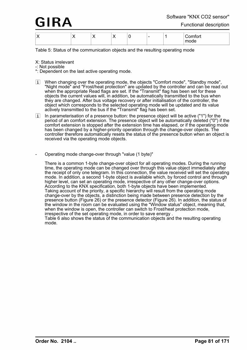
Order No. 2104 ..
X X X X 0 - 1 Comfortmode
Table 5: Status of the communication objects and the resulting operating mode
X: Status irrelevant-: Not possible*: Dependent on the last active operating mode.
i When changing over the operating mode, the objects "Comfort mode", "Standby mode","Night mode" and "Frost/heat protection" are updated by the controller and can be read outwhen the appropriate Read flags are set. If the "Transmit" flag has been set for theseobjects the current values will, in addition, be automatically transmitted to the bus whenthey are changed. After bus voltage recovery or after initialisation of the controller, theobject which corresponds to the selected operating mode will be updated and its valueactively transmitted to the bus if the "Transmit" flag has been set.
i In parameterisation of a presence button: the presence object will be active ("1") for theperiod of an comfort extension. The presence object will be automatically deleted ("0") if thecomfort extension is stopped after the extension time has elapsed, or if the operating modehas been changed by a higher-priority operation through the change-over objects. Thecontroller therefore automatically resets the status of the presence button when an object isreceived via the operating mode objects.
- Operating mode change-over through "value (1 byte)"
There is a common 1-byte change-over object for all operating modes. During the runningtime, the operating mode can be changed over through this value object immediately afterthe receipt of only one telegram. In this connection, the value received will set the operatingmode. In addition, a second 1-byte object is available which, by forced control and throughhigher level, can set an operating mode, irrespective of any other change-over options.According to the KNX specification, both 1-byte objects have been implemented.Taking account of the priority, a specific hierarchy will result from the operating modechange-over by the objects, a distinction being made between presence detection by thepresence button (Figure 26) or the presence detector (Figure 26). In addition, the status ofthe window in the room can be evaluated using the "Window status" object, meaning that,when the window is open, the controller can switch to Frost/heat protection mode,irrespective of the set operating mode, in order to save energy .Table 6 also shows the status of the communication objects and the resulting operatingmode.
Page 81 of 171
Software "KNX CO2 sensor"Functional description

Order No. 2104 ..
Figure 28: Operating mode change-over through KONNEX object with presence button
Figure 29: Operating mode change-over through KONNEX object with presence detector
objectOperatingmodeswitch-over
objectForced objectOperatingmode
objectWindo-wstatus
Pres-encebutto-n
Pres-encedetect-or
Operating mode
00 00 0 X 0 undefined status, nomodification
01 00 0 0 - Comfort mode
02 00 0 0 - Standby mode
03 00 0 0 - Night operation
04 00 0 0 - Frost/heat protection
01 00 0 1 - Comfort mode
02 00 0 1 - Comfort mode
Page 82 of 171
Software "KNX CO2 sensor"Functional description

Order No. 2104 ..
03 00 0 1 - Comfort ex-tension
04 00 0 1 - Comfort ex-tension
01 00 0 - 0 Comfort mode
02 00 0 - 0 Standby mode
03 00 0 - 0 Night operation
04 00 0 - 0 Frost/heat protection
X 00 0 - 1 Comfort mode
X 00 1 - X Frost/heat protection
X 00 1 X - Frost/heat protection
X 01 X X X Comfort mode
X 02 X X X Standby mode
X 03 X X X Night operation
X 04 X X X Frost/heat protection
Table 6: Status of the communication objects and the resulting operating modeX: Status irrelevant-: Not possible
i When changing over the operating mode, the KNX change-over object is updated by thecontroller and can be read out if the "Read" flag is set. If the "Transmit" flag has been setfor this object the current value will, in addition, be automatically transmitted to the buswhen it is changed.After a device reset, the value corresponding to the set operating mode will be activelytransmitted to the bus if the "Transmit" flag has been set.
i In parameterisation of a presence button: the presence object will be active ("1") for theperiod of an active comfort extension. The presence object will be automatically deleted("0") if the comfort extension is stopped after the extension time has elapsed, or if theoperating mode has been changed by a higher-priority operation through the change-overobjects or by local control or a forced operating mode is deactivated by the KNX forcedobject (forced object -> "00"). The controller therefore automatically resets the status of thepresence button when an object value is received via the operating mode objects or theforced object is reset.
Page 83 of 171
Software "KNX CO2 sensor"Functional description

Order No. 2104 ..
Additional information on the Presence function / Comfort extension
With presence detection, the room temperature controller can quickly change over to a comfortextension upon push button actuation or go into the Comfort mode when movement by a personin the room is detected. In this connection, the "Presence detection" parameter in the "Roomtemperature control -> Controller functionality" parameter node sets whether presence detectionshould be movement-controlled by a presence detector or manual through presence buttonactuation.
- Presence detection by the presence buttonPresence detection by the presence button is configured under "Controller functionality".Then the "presence object" is enabled, too. In this way, you can actuate the presencebutton or use a presence object value = "1" to change over to comfort extension when theNight or the Frost/heat protection mode is active (not activated by the "window status"object). The extension will be automatically deactivated as soon as the configured "Lengthof comfort extension" time has elapsed. If you press the presence button once more, or ifthe presence object receives a value ="0", you can deactivate the comfort extension earlier.You cannot re-trigger such extension time.If you have set the length of comfort extension to "0" in the ETS, you cannot activate acomfort extension from the night or frost/heat protection mode. In this case, the operatingmode will not be changed, although the presence function has been activated.If the standby mode is active you can operate the presence button or use a presenceobject value = "1" to change over to the comfort mode. This will also be the case if youhave configured the length of comfort extension to "0". The comfort mode will remain activeas long as the presence function remains active, or until another operating mode comesinto effect.The presence object or the presence function, respectively, will always be deletedwhenever a change-over to a different operating mode takes place, or after a forcedoperating mode has been deactivated (associated with KNX forced change-over). Apresence function activated before a device reset (programming operation, bus voltagefailure) is always deleted, along with the object value, after the reset.
- Presence detection by the presence detectorIf a motion detector is configured for motion detection, then the controller only evaluatesthe "Presence object". With this object, it is possible to integrate presence detectors intoroom temperature control. If a movement is detected ("1" telegram) the controller willchange over into the Comfort mode. In this connection, it is irrelevant what has been set bythe change-over objects directly on the device. Only a window contact or the KNX forcedobject are of higher priority.After the movement delay time has elapsed in the presence detector ("0" telegram), thecontroller will return to the operating mode which was active before presence detection, orit will compensate the telegrams of the operating mode objects received during presencedetection, respectively. During active presence detection, you cannot change-over theoperating mode on the room temperature controller.A presence function activated before a device reset (programming operation, bus voltagefailure) is always deleted, along with the object value, after the reset. In this case, thepresence detector must transmit a new "1" telegram to the controller to activate thepresence function.
Additional information on the window status and the automatic frost protection
The room temperature controller offers various options to change over into the Frost/heatprotection mode. In addition to switching-over by means of the corresponding operating modeswitch-over object, the frost/heat protection can be activated by a window contact, oralternatively, the frost protection can be activated by an automatic temperature function. Withthese options, the window contact or the automatic function has higher priority. You can use the"frost/heat protection" parameter in the "room temperature control -> controller general"parameter branch to set the way how such higher-priority switch-over will take place...
Page 84 of 171
Software "KNX CO2 sensor"Functional description
Order No. 2104 ..
- Frost/heat protection switch-over "via window status"The 1-bit object, "window status" is enabled. A telegram having the value of = "1" (openwindow) and sent to this object will activate the frost/heat protection mode. If this is thecase, the operating mode cannot be deactivated by the switch-over object (except for theKNX forced object). Only a telegram with the value of = "0" (closed window) will reset thewindow status and deactivate the frost/heat protection mode. After this, the operating modeset before the opening of the window or that mode carried by the bus while the window wasopen will be activated.You can optionally configure a window status delay. Such delay can make sense if shortventilation of the room by opening the window is not supposed to change the operatingmode. You can use the "window status delay" parameter to set this delay time between 1and 255 minutes. The window status will only be changed and thus the frost/heat protectionmode activated after this parameterized time has elapsed. A setting of "0" will effect theimmediate activation of the frost/heat protection mode when the window is open. Thewindow status will be in effect in the heating and in the cooling mode. The value of theobject "window status" is deleted after a reset.
- Frost protection mode switch-over by "automatic frost protection"For this setting, automatic switch-over to the frost protection mode can be made at times,depending on the room temperature determined. If there are no window contacts, thissetting can prevent unnecessary heating up of the room when windows or external doorsare open. In connection with this function, a quick temperature drop can be detected bymeasuring the actual temperature every minute as, for example, is the case when awindow is open. If the temperature decrease detected reaches a parameterised value theroom temperature regulator will automatically switch over to the frost protection mode. Youcan use the "automatic frost protection temperature drop" parameter to set the maximumtemperature drop in K/min for switching over to the frost protection mode. After the timepreset by the "frost protection period in automatic mode" parameter has elapsed, theregulator will return into the mode which was set before frost protection. Re-triggering willnot be possible.If a new operating mode was received during the frost protection when switching over by1-byte via the KNX switch-over object, this tracked mode is set according to the automaticfrost protection. If a switch-over was made by 4 x 1 bit during frost protection via thechange-over object, then this newly received mode will be discarded after the end of theautomatic frost protection. The controller then remains in frost protection. Only after thatcan the operating mode be switched over by the objects. The KNX override object has ahigher priority than the automatic frost protection mode and can interrupt the latter.
i The automatic frost protection mode only acts on heating for temperatures below the setvalue temperature of the operating mode selected. Thus, no automatic switchover to frostprotection can take place at room temperatures in the deadband or in the active coolingmode if the "Heating and cooling" operating mode is on. Automatic heat protectionactivation is not intended with this parameterization.
i Frequent draughts in a room can cause unintentional activation/deactivation of frostprotection when the automatic frost protection mode is active, and if the parameterizedtemperature decrease is not low enough. Therefore switching into the frost/heat protectionmode by window contacts should generally be preferred to the automatic option.
Additional information on the operating mode after a reset
In the ETS, it is possible to use the "Operating mode after reset" parameter in the "Roomtemperature control -> Controller general" parameter node to set which operating mode shouldbe activated after bus voltage recovery or re-programming by the ETS. The following settingsare possible...
Page 85 of 171
Software "KNX CO2 sensor"Functional description

Order No. 2104 ..
- "Comfort operation" -> The comfort mode will be activated after the initialisation phase.- "Standby mode" -> The standby mode will be activated after the initialisation phase.- "Night operation" -> The night mode will be activated after the initialisation phase.- "Frost/heat protection operation" -> The frost/heat protection mode will be activated after
the initialisation phase.- "Restore operation mode before reset" -> The mode set before a reset according to the
operating mode object will be restored after the initializing phase of the device. Operatingmodes set by a function with a higher priority before the reset (Forced, Window status,Presence status) are not effected.
The operating mode objects will be updated after a reset.
i Note on the "restore operation mode before reset" setting:Frequent changing of the operating mode (e. g. several times a day) during runningoperation can adversely affect the life of the device as the read-only memory (EEPROM)used has been designed for less frequent write access events only.
Page 86 of 171
Software "KNX CO2 sensor"Functional description

Order No. 2104 ..
4.2.4.4.5 Temperature setpoints
Setpoint temperature presettingTemperature setpoints can be preset for each operating mode in the ETS as part of firstconfiguration. It is possible to configure the setpoints for the "Comfort", "Standby" and "Night"modes directly (absolute setpoint presetting) or relatively (derivation from basic setpoint). Thesetpoint temperatures can later be adapted during regular operation if desired, controlled by theKNX communication objects.i The "Frost/heat protection" operating mode allows the separate configuration of two
temperature setpoints for heating (frost protection) and cooling (heat protection) solely inthe ETS. These temperature values cannot be changed later during controller operation.
The "Setpoint presetting" parameter on the parameter page "Room temperature control ->Controller general -> Setpoints" defines the way the setpoint temperature is preset...- "Relative (setpoint temperatures from basic setpoint)" setting:
When presetting the set-temperatures for comfort, standby and night mode, attention hasto be paid to the fact that all setpoints depend on each other as all values are derived fromthe basic temperature (basic setpoint). The "Basic temperature after reset" parameter in the"Room temperature control -> Controller general -> Setpoints" parameter page determinesthe basic setpoint, which is loaded when the device is programmed via the ETS. Takinginto account the "Reduce / increase the setpoint temperature in standby mode" or "Reduce/ increase the setpoint temperature in night mode" parameters the temperature setpointsfor the standby and night mode are derived from this value depending on the heating orcooling operating mode. The deadband will be additionally considered for the "Heating andcooling" operating mode. The 2-byte object "Basic setpoint" provides the option of changing the basic temperature,and thus all the dependent setpoint temperatures during device operation. A change via theobject must always be enabled in the ETS by configuring the parameter "Change the basictemperature setpoint via bus" to "Approve". If the basic setpoint adjustment via the bus isdisabled, the "Basic setpoint" object will be hidden. The controller rounds the temperaturevalues received via the object to the configured interval of the basic setpoint shift(0.1 K or 0.5 K).
- "Absolute (independent setpoint temperatures)" settingThe setpoint temperatures for comfort, standby and night mode are independent of eachother. Depending on the operating mode and heating/cooling mode, various temperaturevalues can be specified in the ETS within the range +7.0 °C to +40.0 °C. The ETS plug-indoes not validate the temperature values. It is thus possible, for example, to select smallersetpoint temperatures for cooling mode than for heating mode, or to specify lowertemperatures for comfort mode than for standby mode.After commissioning using the ETS the setpoint temperatures can be changed via the busby means of temperature telegrams. This can be done using the communication object"Setpoint active operating mode". When the controller receives a telegram via this object, itimmediately sets the received temperature as the new setpoint of the active operatingmode, and operates from then on with this setpoint. In this manner it is possible to adaptthe setpoint temperatures of all operating modes separately for eating and cooling mode.The frost or heat protection temperature programmed in using the ETS cannot be changedin this manner.
i With absolute setpoint presetting there is no basic setpoint and also no deadband in themixed operating mode "Heating and cooling" (if necessary also with additional level).Consequently, the room temperature controller cannot control the switchover of theoperating mode automatically, which is why, in this configuration, the setting for theparameter "Switchover between heating and cooling" is fixed in the ETS to "Via object".Furthermore, setpoint shifting does not exist for absolute setpoint presetting.
The temperature setpoints programmed in the room temperature controller by the ETS duringcommissioning can be changed via communication objects. In the ETS the parameter
Page 87 of 171
Software "KNX CO2 sensor"Functional description
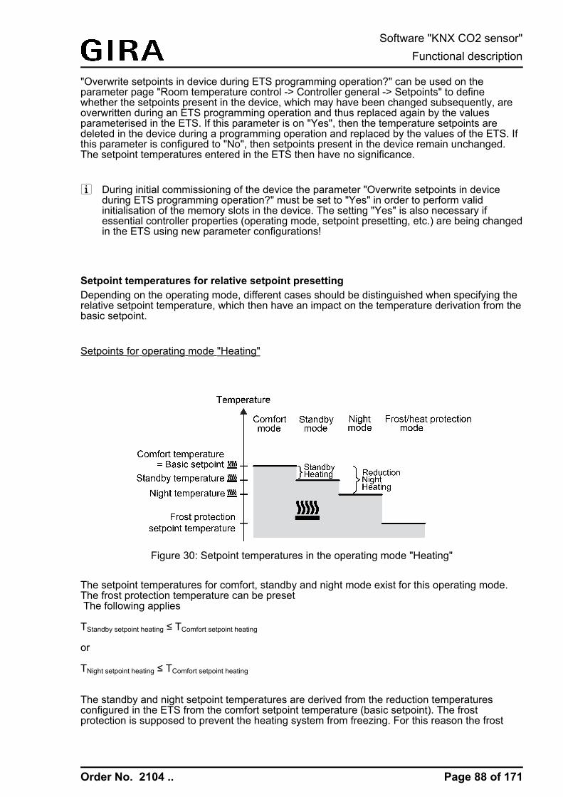
Order No. 2104 ..
"Overwrite setpoints in device during ETS programming operation?" can be used on theparameter page "Room temperature control -> Controller general -> Setpoints" to definewhether the setpoints present in the device, which may have been changed subsequently, areoverwritten during an ETS programming operation and thus replaced again by the valuesparameterised in the ETS. If this parameter is on "Yes", then the temperature setpoints aredeleted in the device during a programming operation and replaced by the values of the ETS. Ifthis parameter is configured to "No", then setpoints present in the device remain unchanged.The setpoint temperatures entered in the ETS then have no significance.
i During initial commissioning of the device the parameter "Overwrite setpoints in deviceduring ETS programming operation?" must be set to "Yes" in order to perform validinitialisation of the memory slots in the device. The setting "Yes" is also necessary ifessential controller properties (operating mode, setpoint presetting, etc.) are being changedin the ETS using new parameter configurations!
Setpoint temperatures for relative setpoint presettingDepending on the operating mode, different cases should be distinguished when specifying therelative setpoint temperature, which then have an impact on the temperature derivation from thebasic setpoint.
Setpoints for operating mode "Heating"
Figure 30: Setpoint temperatures in the operating mode "Heating"
The setpoint temperatures for comfort, standby and night mode exist for this operating mode.The frost protection temperature can be preset The following applies
TStandby setpoint heating ≤ TComfort setpoint heating
or
TNight setpoint heating ≤ TComfort setpoint heating
The standby and night setpoint temperatures are derived from the reduction temperaturesconfigured in the ETS from the comfort setpoint temperature (basic setpoint). The frostprotection is supposed to prevent the heating system from freezing. For this reason the frost
Page 88 of 171
Software "KNX CO2 sensor"Functional description

Order No. 2104 ..
protection temperature (default: +7 °C) should be to a set smaller value than the nighttemperature. In principle, however, it is possible to select frost protection temperature valuesbetween +7.0 °C and +40.0 °C. The possible range of values for a setpoint temperature liesbetween +7.0 °C and +99.9 °C for "heating" and is bounded by the frost protectiontemperature in the lower range.The level offset configured in ETS will be additionally considered in a two-level heating mode.
Figure 31: Setpoint temperatures in the operating mode "Basic and additional heating"
TComfort setpoint additional level heating ≤ TComfort setpoint basic level heatingTStandby setpoint additional level heating ≤ TStandby setpoint basic level heatingTStandby setpoint heating ≤ TComfort setpoint heating
or
TComfort setpoint additional level heating ≤ TComfort setpoint basic level heatingTNight setpoint additional level heating ≤ TNight setpoint basic level heatingTNight setpoint heating ≤ TComfort setpoint heating
Setpoints for the "cooling" operating mode
Figure 32: Setpoint temperatures in the operating mode "Cooling"
The setpoint temperatures for comfort, standby and night mode exist for this operating mode.The heat protection temperature can be presetThe following applies…
Page 89 of 171
Software "KNX CO2 sensor"Functional description

Order No. 2104 ..
TComfort setpoint cooling ≤ TStandby setpoint cooling
or
TComfort setpoint cooling ≤ TNight setpoint cooling
The standby and night set-temperatures are derived after the configured increase temperaturesfrom the comfort set-temperature (basic setpoint). The heat protection is supposed to ensurethat the temperature does not exceed the maximum permissible room temperature in order toprotect system components. For this reason the heat protection temperature (default: +35 °C)should be set to a larger value than the night temperature. In principle, however, it is possible toselect heat protection temperature values between +7.0 °C and +45.0 °C.The possible range of values for a setpoint temperature lies between -99.9 °C and +45.0 °C for"Cooling" and is bounded by the heat protection temperature in the upper range.
The level offset configured in ETS will be additionally considered in a two-level cooling mode.
Figure 33: Setpoint temperatures in the operating mode "Basic and additional cooling"
TComfort setpoint basic level heating ≤ TComfort setpoint additional level heatingTStandby setpoint basic level heating ≤ TStandby setpoint additional level heatingTComfort setpoint cooling ≤ TStandby setpoint cooling
or
TComfort setpoint basic level heating ≤ TComfort setpoint additional level heatingTNight setpoint basic level heating ≤ TNight setpoint additional level heatingTComfort setpoint cooling ≤ TNight setpoint cooling
Setpoints for the "heating and cooling" operating mode
Page 90 of 171
Software "KNX CO2 sensor"Functional description

Order No. 2104 ..
Figure 34: Setpoint temperatures in the operating mode "Heating and cooling" with symmetricaldeadband
Figure 35: Setpoint temperatures in the operating mode "Heating and cooling" withasymmetrical deadband
Page 91 of 171
Software "KNX CO2 sensor"Functional description

Order No. 2104 ..
For this heating/cooling operating mode, the setpoint temperatures of both heating/coolingmodes exist for the Comfort, Standby and Night operating modes as well as the deadband. Adistinction is made in the deadband position with combined heating and cooling. A symmetricalor an asymmetrical deadband position can be configured. In addition, the frost protection andthe heat protection temperatures can be preset.The following applies…
TStandby setpoint heating ≤ TComfort setpoint heating ≤ TComfort setpoint cooling ≤ TStandby setpoint cooling
or
TNight setpoint heating ≤ TComfort setpoint heating ≤ TComfort setpoint cooling ≤ TNight setpoint cooling
The set-temperatures for "Standby" and "Night" are derived from the comfort setpointtemperatures for heating or cooling. The temperature increase (for cooling) and the temperaturedecrease (for heating) of both operating modes can be preset in ETS. The comfort temperaturesitself are derived from the deadband and the basic setpoint.The frost protection is supposed to prevent the heating system from freezing. For this reasonthe frost protection temperature (default: +7 °C) should be set to a smaller value than the nighttemperature for heating. In principle, however, it is possible to select frost protectiontemperature values between +7.0 °C and +40.0 °C. The heat protection is supposed to ensurethat the temperature does not exceed the maximum permissible room temperature in order toprotect system components. For this reason the heat protection temperature (default: +35 °C)should be set to a larger value than the night temperature for cooling. In principle, however, it ispossible to select heat protection temperature values between +7.0 °C and +45.0 °C.The possible range of values for a setpoint temperature ("heating and cooling") lies between+7.0 °C and +45.0 °C and is bounded by the frost protection temperature in the lower range andby the heat protection temperature in the upper range.
The level offset configured in ETS will be additionally considered in a two-level heating orcooling mode.
Page 92 of 171
Software "KNX CO2 sensor"Functional description

Order No. 2104 ..
Figure 36: Setpoint temperatures in the operating mode "Basic and additional heating andcooling" with symmetrical deadband
Page 93 of 171
Software "KNX CO2 sensor"Functional description

Order No. 2104 ..
Figure 37: Setpoint temperatures in the operating mode "Basic and additional heating andcooling" with asymmetrical deadband
TComfort setpoint add. level Heating ≤ TComfort setpoint basic level Heating ≤ TComfort setpoint basic level Cooling ≤ TComfortsetpoint add. level CoolingTStandby setpoint add. level Heating ≤ TStandby setpoint basic level Heating ≤ TStandby setpoint basic level Cooling ≤ TStandbysetpoint add. level CoolingTStandby setpoint heating ≤ TComfort setpoint heating ≤ TComfort setpoint cooling ≤ TStandby setpoint cooling
or
TComfort setpoint add. level Heating ≤ TComfort setpoint basic level Heating ≤ TComfort setpoint basic level Cooling ≤ TComfortsetpoint add. level CoolingTNight setpoint add. level Heating ≤ TNight setpoint basic level Heating ≤ TNight setpoint basic level Cooling ≤ TNight setpoint add. levelCoolingTNight setpoint heating ≤ TComfort setpoint heating ≤ TComfort setpoint cooling ≤ TNight setpoint cooling
deadband and deadband positions in the combined heating and cooling operating mode
With relative setpoint presetting, the comfort setpoint temperatures for heating and cooling arederived from the basic setpoint in consideration of the adjusted Dead band. The deadband(temperature zone for which there is neither heating nor cooling) is the difference between thecomfort setpoint temperatures. This deadband does not exist for absolute setpoint presetting.
Page 94 of 171
Software "KNX CO2 sensor"Functional description

Order No. 2104 ..
The "deadband between heating and cooling", "deadband position" parameters as well as the"Basic temperature after reset" parameter are preset in the ETS configuration. Onedistinguishes between the following settings...
- deadband = "symmetrical"The deadband preset in the ETS is divided into two parts at the basic setpoint. The comfortsetpoint temperatures are derived directly from the basic setpoint resulting from the halfdeadband.The following applies...TBasic setpoint – ½Tdeadband = TComfort heating setpoint
and
TBasic setpoint + ½Tdeadband = TComfort setpoint cooling-> TComfort cooling setpoint – TComfort heating setpoint = Tdeadband-> TComfort cooling setpoint ≥ TComfort heating setpoint
- deadband position = "Asymmetrical"With this setting the comfort setpoint temperature for heating equals the basic setpoint. Thedeadband preset in the ETS is effective only from the basic setpoint in the direction ofcomfort temperature for cooling. Thus the comfort set-temperature for cooling is deriveddirectly from the comfort setpoint for heating.The following applies...TBasic setpoint = TComfort heating setpoint-> TBasic setpoint + Tdeadband = TComfort cooling setpoint-> TComfort cooling setpoint – TComfort heating setpoint = Tdeadband-> TComfort cooling setpoint ≥ TComfort heating setpoint
Page 95 of 171
Software "KNX CO2 sensor"Functional description
Order No. 2104 ..
Accept setpoints permanently
If the basic setpoint has been modified by the communication objects "Basic setpoint" or"Setpoint of active operating mode", two possible cases can be distinguished, which are set bythe parameter "Permanently apply change to basic temperature setpoint" (with relative setpointpresetting) or "Accept modification of the setpoint permanently" (with absolute setpointpresetting)...
- Case 1: The setpoint adjustment is permanently accepted ("Yes" setting):If, with this setting, the temperature setpoint is adjusted, the controller saves the valuepermanently to the EEPROM (permanent storage). The newly adjusted value will overwritethe initial value, i.e. the basic temperature originally configured via the ETS after a reset orthe absolute setpoint temperature loaded using the ETS. The changed values are alsoretained after a device reset, after a switchover of the operating mode or after a switchoverof the heating/cooling mode (with absolute setpoint specification individually for eachoperating mode for heating and cooling).With this setting, it should be noted that frequent changing of the basic temperature (e.g.several times a day because of cyclical telegrams) can affect the product life of the deviceas the non-volatile storage is designed for less frequent write access.The "Basic setpoint" object (relative setpoint presetting) is not bidirectional, meaning that ashifted basic setpoint is not signalled back to the KNX. The object "Setpoint activeoperating mode" (absolute setpoint presetting) can be bidirectional if necessary (set"Transmit" flag!). This makes it possible to use this object to feedback to the bus thesetpoint temperature resulting from a setpoint shift.
- Case 2: The basic setpoint adjustment is only temporarily accepted ("No" setting):The setpoints received via the objects remain active only temporarily. In case of a busvoltage failure, after a switchover to another operating mode (e.g. Comfort to Standby, oralso Comfort to Comfort), or after a switchover of the heating/cooling mode (e.g. Heating toCooling), the last setpoint changed will be discarded and replaced by the initial value.
i If the setpoint is accepted on a non-temporary basis ("Yes" setting), the setpoints restoredafter a device reset are not effected immediately in the communication objects. Only afterthe telegrams have been received from the bus via the objects and the room temperaturecontroller accepts the newly received setpoint can the objects be read out, for example forvisualisation purposes (Set "Read" flag!).
i With relative setpoint presetting: Independent of the "Permanently apply change to basictemperature setpoint" parameter, the temperature setpoints for the standby or night modeor "cooling" comfort mode (deadband) will always be stored in the non-volatile EEPROMmemory.With absolute setpoint presetting: As described, dependent on the "Accept modification ofthe setpoint permanently" parameter, the temperature setpoints for the standby or nightmode for heating or cooling will always be stored in the volatile or non-volatile memory.
Basic setpoint shift for relative setpoint presetting In addition to presetting individual temperature setpoints by the ETS or basic setpoint object,the user, when presetting relative setpoints, can shift the basic setpoint in predefined limitswithin a specific range. When doing so, the basic setpoint is adjusted up or down in levels. Thevalue of a level can be adjusted to 0.1 K or 0.5 K by the parameter "Value of the setpoint shift".i No basic setpoint shift can be performed if the controller is configured for absolute setpoint
presetting.
Page 96 of 171
Software "KNX CO2 sensor"Functional description

Order No. 2104 ..
i It has to be considered that a shift of the displayed setpoint temperature (temperatureoffset of the basic temperature) will directly affect the basic setpoint and as a result shift allother temperature setpoints.A positive shift is possible up to the configured heat protection temperature. A negativeshift is possible up to the set frost protection temperature.
i The "Basic setpoint" object is not bidirectional, meaning that a shifted basic setpoint is notsignalled back to the KNX.
Whether a basic setpoint shifting only affects the currently active operating mode or whether itinfluences all other set-temperatures of the remaining operating modes is determined by the"Permanently apply change to basic setpoint shift" parameter in the "Room temperature control-> Controller general -> Setpoints" parameter page...
- "No" setting:The basic setpoint shifting carried out is in effect for only as long as the operating mode orheating/cooling mode has not changed or the basic setpoint is maintained. Otherwise thesetpoint shift will be reset to "0".
- Setting "yes":In general, the shifting of the basic setpoint carried out affects all operating modes. Theshift is maintained even after a switchover of the operating mode or the heating/coolingmode or adjusting the basic setpoint.
i Since the value for the basic setpoint shift is stored exclusively in volatile memory (RAM),the shift will get lost in case of a reset (e.g. bus voltage failure).
i A setpoint shift does not affect the temperature setpoints for frost or heat protection!
Communication objects for the basic setpoint shift:
The setpoint shift of the controller can be adjusted externally by the communication object"Setpoint shift specification" with a 1-byte counter value (in compliance with KNX DPT 6.010 –Depiction of positive and negative values in a double complement. By connecting to the"Setpoint shift specification" object the controller extensions are able to directly adjust thecurrent setpoint shift of the controller. As soon as the controller receives a value, it will adjustthe setpoint shift correspondingly. Values that lie within the possible value range of the basicsetpoint shift can be directly jumped to.The controller monitors the received value independently. As soon as the external preset valueexceeds the limits of the adjustment options for the setpoint shift in positive or negativedirection, the controller will correct the received value and adjust the setpoint shift to maximum.Depending on the direction of the shift, the value feedback is set to the maximum value via thecommunication object "Current setpoint shift".
The current setpoint shift is tracked by the controller in the communication object "Currentsetpoint shift". This object has the same data point type and value range as the object "Setpointshift specification" (see above). By connecting to this object the controller extensions are alsoable to display the current setpoint shift. As soon as there is an adjustment by one temperatureincrement in positive direction, the controller counts up the value. The counter value will becounted down if there is a negative adjustment of the temperature. A value of "0" means that nosetpoint shifting has been adjusted.
Example:Initial situation: Current setpoint temperature = 21.0 °C / value of the setpoint shift = 0.5 K / /
Page 97 of 171
Software "KNX CO2 sensor"Functional description
Order No. 2104 ..
counter value in the object "Current setpoint shift" = "0" (no setpoint shift active)After the setpoint shifting:-> A setpoint shift by one temperature increment in the positive direction will count up the valuein the "Current setpoint shift" object by one = "1".-> Current setpoint temperature = 21.5°C-> An additional setpoint shift by one temperature increment in the positive direction will againcount up the value in the "Current setpoint shift" object by one = "2".-> Current setpoint temperature = 22.0°C-> A setpoint shift by one temperature increment in the negative direction will count down thevalue in the "Current setpoint shift" object by one = "1".-> Current setpoint temperature = 21.5°C-> An additional setpoint shift by one temperature increment in the negative direction will againcount down the value in the "Current setpoint shift" object by one = "0".-> Current setpoint temperature = 21.0°C-> An additional setpoint shift by one temperature increment in the negative direction will againcount down the value in the "Current setpoint shift" object by one = "-1".-> Current setpoint temperature = 20.5°C, etc. ...
i To ensure that controller extensions indicate the correct shifts and also control thefunctions of the controller (as main unit) correctly, it is necessary for the controllerextensions to be set to the same shift limits of the setpoint shift as the main unit. Controllerextensions must also be set to the same step width for the setpoint shift as the controlleritself (0.1 K or 0.5 K).
Transmitting the setpoint temperatureThe setpoint temperature, which is given by the active operating mode can be activelytransmitted onto the bus via the 2-byte "Set temperature" object. The "Transmission at setpointtemperature modification by..." parameter in the "Room temperature control -> controllergeneral -> setpoint values" parameter node determines the temperature value by which thesetpoint has to change in order to have the setpoint temperature value transmitted automaticallyvia the object. Possible temperature value changes lie within a range of 0.1 K and 25.5 K. Thesetting "0" at this point will deactivate the automatic transmission of the setpoint temperature.
In addition, the setpoint can be transmitted periodically. The "Cyclical transmission of setpointtemperature" parameter determines the cycle time (1 to 255 minutes). The value "0" willdeactivate the periodical transmission of the setpoint temperature value. It has to be pointed outthat with deactivated periodical transmission and deactivated automatic transmission, nosetpoint temperature telegrams will be transmitted in case of a change.Setting the "Read" flag on the "Setpoint temperature" object makes it possible to read out thecurrent setpoint. Following the return of bus voltage or after re-programming via the ETS, theobject value will be initialised according to the current setpoint temperature value and activelytransmitted to the bus.
Page 98 of 171
Software "KNX CO2 sensor"Functional description

Order No. 2104 ..
4.2.4.4.6 Room temperature measurement
Basic principlesThe room temperature regulator periodically measures the actual temperature of the room andcompares it with the given setpoint temperature of the active operating mode. The controlalgorithm calculates the adjusted command value from the difference between actual andsetpoint temperatures. In order to ensure a fault-free and effective room temperature control, itis very important to determine the exact actual temperature.The room temperature controller possesses an integrated temperature sensor, using which theroom temperature can be detected. Alternatively (e.g. if the room temperature controller hasbeen installed in an unfavourable location or operates in difficult conditions, for example, in amoist atmosphere) or in addition (e.g. in large rooms or halls), a second temperature sensorlinked via bus telegrams can be used to determine the actual value. This second sensor caneither be a room temperature controller coupled via the KNX or a controller extension withtemperature recording.
When choosing the installation location of the controller or the external sensor, the followingpoints should be considered...- The controller or temperature sensor should not be used in multiple combinations,
especially together with flush-mounted dimmers.- Do not install the temperature sensor in the area of large electrical consumers (avoid heat
influences).- The push button sensor should not be installed in the vicinity of radiators or cooling
systems.- The temperature sensor should not be exposed to direct sun.- The installation of sensors on the inside of an outside wall might have a negative impact on
the temperature measurement.- Temperature sensors should be installed at least 30 cm away from doors, windows or
ventilation units and at least 1.5 m above the floor.
i Room temperature measurement by the device is always active, irrespective of the "Roomtemperature control" function and can thus be used independently (e.g. for simplemeasurement and display of a room temperature without control).
Temperature detection and measured value formation
The parameter "Temperature detection" in the parameter node "Sensor -> Temperaturemeasurement" specifies by which sensor the room temperature is determined.The following settings are possible for temperature detection
- "internal sensor"The temperature sensor integrated in the room temperature controller is activated. Thus,the actual temperature value is determined only locally on the device.In this configuration, the feedback control will start directly after a device reset.
Page 99 of 171
Software "KNX CO2 sensor"Functional description
Order No. 2104 ..
- "received temperature value"The actual temperature is determined solely via a temperature value received from the bus.In this case, the sensor must either be a KNX room thermostat coupled via the2-byte object "Received temperature" or a controller extension with temperature detection.The room temperature controller can request the current temperature value cyclically. Forthis purpose, the parameter "Request time of the received temperature value" must be setto a value > "0". The request interval can be configured within the limits of1 minute to 255 minutes.After a device reset the room temperature controller will first wait for a valid temperaturetelegram until the feedback control starts and a command value, if applicable, is output.
- "internal sensor + received temperature value"This setting is used to combine the selected temperature sources. The sensors can eitherbe a KNX room thermostat coupled via the 2-byte object "received temperature" orcontroller extensions with temperature detection.With the setting "Received temperature value" the room temperature controller can requestthe current temperature value cyclically. For this purpose, the parameter "Request time ofthe received temperature value" must be set to a value > "0". The request interval can beconfigured within the limits of 1 minute to 255 minutes. After a device reset the roomtemperature controller will first wait for a valid temperature telegram until the feedbackcontrol starts and a command value, if applicable, is output.When evaluating, the real actual temperature is made up from the two respectivemeasured temperature values. At the same time, the weighting of the temperature values isdefined by the parameter "Measured value formation to receive internally". Depending onthe different locations of the sensors or a possible non-uniform heat distribution inside theroom, it is thus possible to adjust the actual temperature measurement. Often, thosetemperature sensors that are subject to negative external influences (for example,unfavourable location because of exposure to sun or heater or door / window directly nextto it) are weighted less heavily.
Example: a room temperature controller is installed next to the entrance to the room(internal sensor). An additional wired temperature sensor has been mounted on an innerwall in the middle of the room below the ceiling.Internal sensor: 21.5 °CExternal sensor: 22.3 °CDetermination of measured value: 30 % to 70 %
-> TResult internal = T internal · 0.3 = 6.45 °C,-> TResult external = Texternal = 22.3 °C · 0.7 = 15.61 °C-> TResult actual = TResult internal + TResult external = 22.06 °C
Calibrating the measured valuesIn some cases during room temperature measurement, it may be necessary to adjust the singletemperature values. Adjustment becomes necessary, for example, if the temperature measuredby the sensors stays permanently below or above the actual temperature in the vicinity of thesensor. To determine the temperature deviation, the actual room temperature should bedetected with a reference measurement using a calibrated temperature measuring device.The parameters "Internal sensor calibration" and "Calibration of received temperature value" inthe parameter node "Sensor -> Temperature measurement" can parameterise the positive(temperature increase, factors: 1 ... 127) or negative (temperature decrease, factors -128... -1)temperature calibration in levels of 0.1 K. Thus, the calibration is made only once statically andis the same for all operating modes of the controller.
i The measured value has to be increased, if the value measured by the sensor lies belowthe actual room temperature. The measured value has to be decreased, if the valuemeasured by the sensor lies above the actual room temperature.
Page 100 of 171
Software "KNX CO2 sensor"Functional description

Order No. 2104 ..
i During room temperature control, the controller always uses the adjusted temperaturevalue to calculate the command values. The adjusted temperature value is transmitted tothe bus via the "Actual temperature" object (see "Transmission of the actual temperature").When determining the measured value using combined sensors, the two adjusted valuesare used to calculate the actual value.
i The object value of the communication object No. 80 (s.measured value for temperature) isthe determined and corrected temperature value of the integrated sensor (self-heating).The parameter "Calibration of internal temperature sensors" is added to the object value asoffset.
i The object value of the communication object No. 23 (actual temperature) is the read outvalue of the communication object No. 80 (S.measured value for temperature), to which theparameterised calibration value was already applied. The application of a parameterisedevaluation and weighting might possibly still take place. This temperature value serves asthe actual temperature for the room temperature controller function
i The object value of the communication object No. 59 (actual temperature non-calibrated) isthe read out value of the communication object No. 80 (S.measured value for temperature)without temperature calibration. This value is the actual room temperature measured by theinternal temperature sensor.
Transmission of the actual temperatureThe determined actual temperature can be actively transmitted to the bus via the2-byte "Actual temperature" object. The parameter "Transmission when room temperaturechange by..." in the parameter node "Sensor -> Temperature measurement" defines thetemperature value by which the actual value must change so that the actual temperature valueis transmitted automatically via the object. Possible temperature value changes lie within arange of 0.1 K and 25.5 K. Setting to "0" at this point will deactivate the automatic transmissionof the actual temperature.
In addition, the actual value can be transmitted periodically. The "Cyclical transmission of theroom temperature" parameter determines the cycle time (1 to 255 minutes). The value "0" willdeactivate the periodical transmission of the actual temperature value.Setting the "Read" flag on the "actual temperature" object makes it possible to read out thecurrent actual value at any time over the bus. It has to be pointed out that with deactivatedperiodical transmission and deactivated automatic transmission, no more actual-temperaturetelegrams will be transmitted".Following the return of bus voltage, new programming via the ETS, the object value will beupdated according to the actual temperature value and transmitted on the bus. During roomtemperature control, the controller always uses the adjusted temperature value to calculate thecommand values. The adjusted temperature value is transmitted to the bus via the "Actualtemperature" object.If, when using a separate KNX sensor, no temperature value telegram of the separate sensorwas received, only the value formed by the internal sensor is transmitted. If the separate sensoris used exclusively, the value "0" is in the object after a reset. For this reason, the separate KNXtemperature sensor should always transmit the current value after a reset.
Page 101 of 171
Software "KNX CO2 sensor"Functional description

Order No. 2104 ..
4.2.4.4.7 Command value and status output
Command value objectsThe format of the command value objects are determined depending on the control algorithmselected for heating and / or cooling and, if applicable, also for the additional levels. 1 bit or 1byte command value objects can be created in the ETS. The control algorithm calculates thecommand values in intervals of 30 seconds and outputs them via the objects. With the pulsewidth modulated PI control (PWM) the command value is updated, if required, solely at the endof a time cycle.
Possible object data formats for the command values separately for both heating/coolingoperating modes, for the basic and the additional level or for both control circuits are…- continuous PI control: 1 byte- Switching PI control: 1 bit + additionally 1 byte (for example for the status indication with
visualisations),- switching 2-point feedback control: 1 bit.
Depending on the set heating/cooling operating mode, the controller is able to address heatingand / or cooling systems, to determine command values and to output them via separateobjects. One distinguishes between two cases for the "Heating and cooling" mixed operatingmode...- Case 1: Heating and cooling system are two separate systems
In this case the "Transmit heating and cooling command value to one common object"parameter should be set to "No" in the "Room temperature control -> Controller functions"parameter node. Thus, there are separate objects available for each command value,which can be separately addressed via the individual systems.This setting allows to define separate types of control for heating and cooling.
- Case 2: Heating and cooling system are a combined systemIn this case the "Transmit heating and cooling command value to one common object"parameter may be set, if required, to "Yes". This will transmit the command values forheating and cooling to the same object. In case of a two-level feedback control, anothershared object will be enabled for the additional levels for heating and cooling.With this setting it is only possible to define the same type of feedback control for heatingand for cooling as the feedback control and the data format must be identical. The ("Typeof heating / cooling") control parameter for cooling and heating still has to be definedseparately.A combined command value object may be required, for example, if heating as well ascooling shall take place via a single-pipe system (combined heating and cooling system).For this, the temperature of the medium in the single-pipe system must be changed via thesystem control. Afterwards the heating/cooling operating mode is set via the object (oftenthe single-pipe system uses cold water for cooling during the summer, hot water for heatingduring the winter).
If required, the command value can be inverted before the transmission to the KNX. With outputvia a combined object, the parameters "Output of heating command value", "Output of coolingcommand value" or "Output of command values..." output the command value in invertedfashion according to the object data format. The parameters for inverting the additional level(s)are additionally available in the two-level control.
The following applies…For continuous command values:-> not inverted: Command value 0 % ... 100 %, value 0 ... 255-> inverted: Command value 0 % ... 100 %, value 255 ... 0For switching command values:-> not inverted: Command value off / on, value 0 / 1-> inverted: Command value off / on, value 1 / 0
Page 102 of 171
Software "KNX CO2 sensor"Functional description

Order No. 2104 ..
Automatic transmission
On automatic transmission of the command value telegrams, a distinction is made with regardto the type of control...
- Continuous PI control:In case of a continuous PI control, the room temperature controller calculates a newcommand value periodically every 30 seconds and outputs it to the bus via a1-byte value object. The change interval of the command value can be determined inpercent according to which a new command value is to be output on the bus via the"Automatic transmission on change by..." parameter in the "Room temperature control ->Controller general -> Command values and status output" parameter node. The changeinterval can be configured to "0" so that a change in the command value will not result in anautomatic transmission.In addition to the command value output following a change, the current command valuevalue may be periodically transmitted on the bus. In addition to the times when changesare to be expected, other command value telegrams will be output according to the activevalue after a configurable cycle time. This ensures that, during cyclical security monitoringof the command value in servo drive or in the addressed switch actuator, telegrams arereceived within the monitoring time. The time interval predetermined by the "Cycle time forautomatic transmission..." parameter should correspond to the control interval in theactuator (cycle time in the controller is preferably to be configured smaller). The "0" settingwill deactivate the periodic transmission of the command value.With continuous PI control it must be noted that if the cyclical and the automatictransmission are both deactivated, no command value telegrams will be transmitted in caseof a change!
- Switching PI control (PWM):In case of a switching PI control (PWM), the room temperature controller calculates a newcommand value internally every 30 seconds. With this control, however, the update of thecommand value takes place, if required, solely at the end of a PWM cycle. The parameters"automatic transmission on change by..." and "Cycle time for automatic transmission..." arenot enabled with this control algorithm. The parameter "Cycle time of the switchingcommand value..." defines the cycle time of the PWM command value signal.
- 2-point feedback control:In case of a 2-point feedback control, the room temperature and thus the hysteresis valuesare evaluated periodically every 30 seconds, so that the command values, if required, willchange solely during these times. The "Automatic transmission on change by..." parameteris not enabled as this control algorithm does not calculate continuous command values.In addition to the command value output following a change, the current command valuevalue may be periodically transmitted on the bus. In addition to the times when changesare to be expected, other command value telegrams will be output according to the activevalue after a configurable cycle time. This ensures that, during cyclical security monitoringof the command value in servo drive or in the addressed switch actuator, telegrams arereceived within the monitoring time. The time interval predetermined by the "Cycle time forautomatic transmission..." parameter should correspond to the control interval in theactuator (cycle time in the controller is preferably to be configured smaller). The "0" settingwill deactivate the periodic transmission of the command value.
Page 103 of 171
Software "KNX CO2 sensor"Functional description

Order No. 2104 ..
Controller status
The room temperature controller can transmit its current status to the KNX/EIB. A choice of dataformats is available for this. The "Controller status" parameter in the "Room temperature control-> Controller general -> Command value and status output" parameter branch will enable thestatus signal and set the status format...
- "KNX compliant"The KNX compliant controller status feedback is harmonised on a manufacturer-specificbasis, and consists of 3 communication objects. The 2-byte object "KNX status" (DPT22.101) indicates elementary functions of the controller (see Table 7). This object issupplemented by the two 1-byte objects "KNX status operating mode" and "KNX statusforced operating mode" (DPT 20.102), which report back the operating mode actually seton the controller . The last two objects mentioned above are generally used to enablecontroller extensions to display the controller operating mode correctly in the KNXcompliant status display. Therefore these objects should be connected with controllerextensions if the KNX compliant status feedback is not configured.
Bit of the statustelegram
Meaning
0 Controller error status ("0" = no error / "1" = error)
1 not used (permanent "0")
2 not used (permanent "0")
3 not used (permanent "0")
4 not used (permanent "0")
5 not used (permanent "0")
6 not used (permanent "0")
7 not used (permanent "0")
8 Operating mode ("0" = Cooling / "1" = Heating)
9 not used (permanent "0")
10 not used (permanent "0")
11 not used (permanent "0")
12 Controller disabled (dew point operation) ("0" = Controller enabled/"1" = Controller disabled)
13 Frost alarm ("0" = Frost protection temperature exceeded /"1" = frost protection temperature undershot)
14 Heat alarm ("0" = heat protection temperature exceeded /"1" = Heat protection temperature exceeded)
15 not used (permanent "0")
Table 7: Bit encoding of the 2 byte KNX compliant status telegram
Page 104 of 171
Software "KNX CO2 sensor"Functional description

Order No. 2104 ..
- "Controller general":The general controller status collects essential status information of the controller in two1-byte communication objects. The "Controller status" object contains fundamental statusinformation (see Table 8). The "Status signal addition" object collects in a bit-orientatedmanner further information that is not available via the "Controller status" object(see Table 9). For example, controller extensions can evaluate the additional statusinformation, in order to be able to display all the necessary controller status information onthe extension display.
Bit of the status telegram Meaning0 On "1": Comfort operation activated
1 On "1": Standby mode active
2 On "1": Night mode active
3 On "1": Frost/heat protection mode active
4 On "1": Controller disabled
5 On "1": Heating, on "0": Cooling
6 On "1": Controller inactive (deadband)
7 On "1": Frost alarm (TRoom ≤ +5 °C)
Table 8: Bit encoding of the 1 byte status telegram
Bit of thestatus telegram
Meaning on "1" Meaning on "0"
0 Normal operating mode Forced operating mode
1 Comfort extension active No comfort extension
2 Presence (Presence detector) No presence(Presence detector)
3 Presence (Presence button) No presence(Presence button)
4 Window opened No window opened
5 Additional level active Additional level inactive
6 Heat protection active Heat protection inactive
7 Controller disabled(dew point operation)
Controller not disabled
Table 9: Bit encoding of the 1 byte additional status telegram
Page 105 of 171
Software "KNX CO2 sensor"Functional description

Order No. 2104 ..
- "Transmit individual state"The 1 bit status object "Controller status, ..." contains the status information selected by the"Single status" parameter. Meaning of the status signals:
"Comfort mode active" -> Active if operating mode "Comfort " or a comfort extension "" isactivated.
"Standby mode active" -> active if the "standby " operating mode is activated.
"Night-mode active" -> active if the "night " operating mode is activated.
"Frost/heat protection active" -> active if the "frost/heat protection" operating mode isactivated.
"Controller disabled" -> Active if controller disable is activated (dew point mode).
"Heating / cooling" -> Active if heating is activated and inactive if cooling is activated.Inactive if controller is disabled.
"Controller inactive" -> Active with the "heating and cooling" operating mode when themeasured room temperature lies within the dead zone. This status information is always "0"for the individual "Heating" or "Cooling" operating modes. Inactive if controller is disabled.
"Frost alarm" -> Is active if the detected room temperature reaches or falls below +5 °C.This status signal will have no special influence on the control behaviour.
i Upon a reset, the status objects will be updated after the initialisation phase. After this,updating is performed cyclically every 30 seconds in parallel with the command valuecalculation of the controller command values. Telegrams are only transmitted to the buswhen the status changes.
Command value limitOptionally a command value limit can configured in the ETS. The command value limit allowsthe restriction of calculated command values to the range limits "minimum" and "maximum". Thelimits are permanently set in the ETS and, if command value limitation is active, can be neitherundershot or exceeded during device operation. It is possible, if available, to specify variouslimiting values for the basic and additional stages and for heating and cooling.
i It should be noted that the command value limit has no effect with "2-point feedbackcontrol" and with "Transmitting of command values for heating and cooling via a commonobject"! In that case it is still possible to configure the command value limit in the ETS, but itwill have no function.
The "Command value limit" parameter on the parameter page "Room temperature control ->Controller general -> Command values and status output" defines the mode of action of thelimiting function. The command value limit can either be activated or deactivated using the 1-bitcommunication object "Command value limit", or be permanently active. When controlling viathe object, it is possible to have the controller activate the command value limit automaticallyafter bus voltage return or an ETS programming operation. Here the "Command value limit afterreset" parameter defines the initialisation behaviour. In the "Deactivated" setting, the commandvalue limit is not automatically activated after a device reset. A "1" telegram must first bereceived via the "Command value limit" object for the limit to be activated. In the "Activated"setting, the controller activates the command value limit automatically after a device reset. Todeactivate the limit a "0" telegram must be received via the "Command value limit" object. Thelimit can be switched on or off at any time using the object.
Page 106 of 171
Software "KNX CO2 sensor"Functional description

Order No. 2104 ..
With a permanently active command value limit, the initialisation behaviour cannot beconfigured separately after a device reset, as the limit is always active. In this case it is also notpossible to configure any object.
As soon as the command value limit is active, calculated command values are limited accordingto the limiting values from the ETS. The behaviour with regard to the minimum or maximumcommand value is then as follows...
- Minimum command value:The "Minimum command value" parameter specifies the lower command value limitingvalue. The setting can be made in 5 % increments in the range 5 % ... 50 %. With an activecommand value limit, the set minimum command value is not undershot by commandvalues. If the controller calculates smaller command values, it sets the configured minimumcommand value. The controller transmits a 0% command value if no more heating orcooling energy has to be demanded.
- Maximum command value:The "Maximum command value" parameter specifies the upper command value limitingvalue. The setting can be made in 5 % increments in the range 55 % ... 100 %. With anactive command value limit, the set maximum command value is not exceeded. If thecontroller calculates larger command values, it sets the configured maximum commandvalue.
If the limit is removed, the device automatically repositions the most recently calculatedcommand value to the unlimited values when the next calculation interval for the commandvalues (30 seconds) has elapsed.
i If the controller executes a valve protection function, the command value limit is temporarilydeactivated in order to make use of the full motion range of the valve.
i An active command value limit has a negative effect on the control result when thecommand value range is very restricted. A control deviation must be expected.
Page 107 of 171
Software "KNX CO2 sensor"Functional description

Order No. 2104 ..
Special case for command value 100% (Clipping mode)
If with a PI control the calculated command value of the controller exceeds the physical limits ofthe actuator, in other words if the calculated command value is greater than 100%, then thecommand value is set to the maximum value (100%) and thus limited. This special, necessarycontrol behaviour is also called "clipping". With PI control the command value can reach thevalue "100%" if there is a large deviation of the room temperature from the setpoint temperatureor the controller requires a long time to adjust to the setpoint with the heating or cooling energythat is being applied. The controller can evaluate this state in a particular manner and react to itin various ways.The parameter "Behaviour with command value = 100% (clipping mode PI control)" on theparameter page "Room temperature control -> Controller general -> Command values andstatus output" defines the functions of the PI controller when the command value is 100%...
- "keep 100% until setpoint = actual, then 0%" setting:The controller keeps the maximum command value until the room temperature (actualvalue) reaches the setpoint temperature. After that is reduces the command value down to0% all at once (controller reset).The advantage of this control behaviour is that in this way sustainable heating up ofundercooled rooms or effective cooling of overheated rooms will be achieved byovershooting the setpoint. The disadvantage is the in some circumstances theovershooting of the room temperature may be found disturbing.
- Setting "keep 100% as required, then adjust downwards":The controller maintains the maximum command value only as long as it is necessary.After that it adjusts the command value downwards according to the PI algorithm. Theadvantage of this control characteristic is the fact that the room temperature does notexceed the setpoint temperature at all, or only slightly. The disadvantage is that this controlprinciple increases the tendency to oscillate about the setpoint.
Which of the methods of functioning described above is used often depends on what heating orcooling system is used (underfloor heating, radiators, fan coils, cooling ceilings, etc.), and howeffective these systems are. We recommend selecting the setting "keep 100% until setpoint =actual, then 0%" (default setting). Only if this control behaviour has an adverse effect on thepeople's perception of the temperature in a room should the setting "keep 100% as required,then adjust downwards" be used.
i Clipping may also occur when a command value limit is active (maximum command value).In this case, if the internally calculated command value reaches 100%, then the controlleronly transmits to the bus the maximum command value according to the ETS configuration.The clipping (switching off when setpoint = actual or adjusting downwards) is performed,however.
i It should be noted that the clipping mode has no effect with "2-point feedback control"! Inthat case it is still possible to configure the parameter "Behaviour with command value =100%" in the ETS, but it will have no function.
Page 108 of 171
Software "KNX CO2 sensor"Functional description

Order No. 2104 ..
4.2.4.4.8 Disable functions of the room temperature controller
Disable controllerCertain operation conditions may require the deactivation of the room temperature control.For example, the controller can be switched-off during the dew point mode of a cooling systemor during maintenance work on the heating or cooling system. The parameter "Switch offcontroller (dew point operation)" in the parameter node "Room temperature control -> Controllerfunctionality" enables the 1-bit object "Disable controller" when set to "Via bus". In addition, thecontroller disable function can be switched off when set to "No".
In case a "1" telegram is received via the enabled disable object, the room temperature controlwill be completely deactivated. In this case, the command values are equal "0" (wait 30 s forupdate interval of the command values). The controller, however, can be operated in this case.
The additional stage can be separately disabled when in two-stage heating or cooling mode.When set to "Yes", the "Additional level disabling object" parameter in the "Room temperaturecontrol -> Controller general" parameter node will enable the1 bit "Disable additional level" object. In addition, the disable function of the additional level canbe switched off when set to "No". In case a "1" telegram is received via the enabled disableobject, the room temperature control is completely deactivated by the additional level. Thecommand value of the additional level is "0" while the basic level continues to operate.
i A disable is always deleted after a reset (return of bus voltage, ETS programmingoperation).
Page 109 of 171
Software "KNX CO2 sensor"Functional description

Order No. 2104 ..
4.2.4.4.9 Valve protectionValve protection may be carried out periodically in order to prevent the addressed control valvesof the heater or cooling system from becoming calcified or stuck. When set to "Yes", the "Valveprotection" parameter in the "Room temperature control -> Controller functionality" parameternode activates valve protection.This type of protection is generally started not only for non-active command value objects, i.e.for objects which have not requested any heating or cooling energy over the past 24 hours. Forthese objects, by taking into account the following parameterisation the controller willperiodically set the command value to the maximum value once a day for a duration ofapprox. 5 minutes.
Command value output not inverted:-> 1-bit command value: "1", 1-byte command value: "255"Command value output inverted:-> 1-bit command value: "0", 1-byte command value: "0"
Thus even long closed valves will be opened briefly on a regular basis.
i A controller disable has no influence on the valve protection. This means that valveprotection is carried out, even when the controller is disabled.
i The controller checks the 24-h time cycle for the valve protection based on a 24-hourcounter. (Owing to inaccuracies, it can be assumed that this time will shift.) After a reset ofthe device (programming with the ETS or return of bus voltage), this will be resetautomatically and restarted.
Page 110 of 171
Software "KNX CO2 sensor"Functional description

Order No. 2104 ..
4.2.4.5 Logic gates
Logic gatesIn order to implement logical dependencies from external states as well or to cascade, thedevice software has four logic gates. Each gate can have from one to a maximum of four inputs.For each logic gate, the type of logic operation "AND","OR", "exclusive OR", "AND withfeedback" can be set. In addition, each input can be operated normally or inverted.The communication objects of the outputs can be configured as 1-bit or 1-byte objects.Switching outputs can also work inverted. The inputs can be used separately with their owncommunication objects. Alternatively, an input can be assigned to a limiting value, dew pointalarm or 1-bit logic gate output. The outputs can work with a time delay. The transmissioncriterion for input event, output change and cyclical transmission can be set.For more complex functions it is possible to combine a number of logic gates. Feedback, i.e.connecting an output with an input of the same gate (poss. also via other logic gates) is notprevented by the configuration software. This does not interfere with the other device functions.
i Because feedback can lead to a very large number of telegrams, reasonable switch-on orswitch-off delays should be set in such cases.
i As a rule, a logic operation is only evaluated when an input telegram is received. If afeedback with a cyclically sending output is created, it may occur that the device will sendtelegrams independently after the application is loaded or after a reset. In this case, too,switch-on or switch-off delays are highly advisable.
i With an "AND with return" the value of the output is fed back internally to input 1. The resultof this is that the output can only have the value "1" again if input 1 is set to "1" after thevalue "1" is already present on all of the other inputs. As soon as one of the other inputs isgiven the value "0", the output and thus input 1 is set to "0" because of the feedback.Example: A luminaire that should first be switched on manually at dusk and switched offagain automatically at dawn. Here the push-button is linked to input 1 and the limiting valueof the twilight sensor is linked to input 2. After the twilight sensor has set input 2 to "1", thepush-button on input 1 can be used to switch on the light. If the user forgets to switch thelight off again manually, when daylight comes the feedback ensures that input 1 is resetinternally to "0". Without this feedback the light would be switched on again automatically atthe next twilight.
Parametrizing logic gatesThe following settings must be made in order to use a logic gate...o Configure the "Number of logic gates" required (max. four) on the parameter page
"Configure logic gates".
On the parameter page "Logic gates -> Logic gates X"...o Select the "Type of logic operation".o In the parameter "Number of inputs", select a number of inputs between 1 and 4.o Select the number of outputs and data format in the parameter "Number and type of output
objects".o In parameter "Send output when", select under what precondition the output object should
be sent.o Set the parameter "Transmission behaviour for logic "1".o Set the parameter "Transmission behaviour for logic "0".
Page 111 of 171
Software "KNX CO2 sensor"Functional description

Order No. 2104 ..
i When using the delays, ensure that the time delays can be retriggered. Thus, in the case of"Transmission behaviour for logic 1", a "1" telegram on a gate input always causes a restartof the time delay. A "0" state on a gate output in "Transmission behaviour for logic 0"retriggers the switch-off delay each time. Consequently, input states are only evaluated andoutput states are transmitted to the bus as a telegram only once the time delays haveelapsed completely.This should be observed particularly when input states are sent cyclically to the gate. For acombination of cyclic transmission and delays, the delay times must always be set smallerthan the times for the cyclic transmission.
o In the parameter "Transmit output object(s) cyclically", set whether, and if yes, in whichtime interval the output object or output objects should be sent.
On the parameter page "Logic gate -> Logic gate X -> Inputs" (the following settings can bemade for each of the max. 4 inputs)...o In the parameter "Connection", define whether an internal or external input value should be
assigned. If an "internal input value" should be selected for the input, select the value fromthe list of all internal 1-bit values.
o Define the "behaviour" of the input. A normal or inverted evaluation can be defined.
On the parameter page "Logic gate -> Logic gate X -> Outputs" (the following settings can bemade for each of the possible outputs)...o Set the parameter "Switching command for logic 0 / 1" for 1-bit outputs and "Value for logic
0 / 1" for 1-byte outputs.The logic gate has been completely parameterised.
Page 112 of 171
Software "KNX CO2 sensor"Functional description

Order No. 2104 ..
4.2.4.6 Delivery stateIn the state as delivered, the application program is unloaded. After connecting the bus voltage,the programming LED will therefore start flashing at a fixed frequency of 0.5 Hz. The devicedoes not react any further in this state. It transmits no telegrams to the bus. The physicaladdress is preset to 15.15.255The device has to be programmed and put into operation via the ETS (see chapter 2.4.Commissioning).
Page 113 of 171
Software "KNX CO2 sensor"Functional description

Order No. 2104 ..
4.2.5 Parameters
4.2.5.1 Parameter sensor
Description Values Commenth Sensorh Sensor -> CO2 measurementHeight of location abovesea level(0...2000) * 1 m
0...500...2000 The measured value of the CO2 sensormodule is air pressure dependent. Theparameter "Height of location above sealevel" is provided in order tocompensate for this dependency. Theuser can enter the current locationheight freely here.
Transmit on change ofthe measured value by(Transmission delay:10 s)
inactive0.5%1%3%10%
So as not to burden the bus with veryfrequent telegrams, the measured valueshould not be sent for every tiny change.While taking the measurement task intoaccount, a maximum possible valueshould be set here.The setting here refers to the measuringrange of the CO2 measurement(here: 2000 ppm).
Cycl. sending of themeasured value(0...120) * 10 s;0 = inactive
0 ... 120 Here you can set whether and withinwhich time interval the value istransmitted. The set value multiplied by10 is the repeat time in seconds. It isthus possible to set the cycle time instep widths of 10 seconds.The value "0" means that no cyclicsending is carried out.
Limiting values Inactive1 Limiting value active2 Limiting values active3 Limiting values active4 Limiting values active
Here you can set whether and howmany limiting values are activated forthe CO2 measurement.
Behaviour of the limitingvalue 1 and 2 infrost/heat protectionmode of the controller,Operating mode heatingandoperating mode cooling
No actionsend ONsend OFFON, no telegramOFF, no telegram
The values can be set separatelyaccording to heating operating mode,cooling operating mode for the limitingvalues 1 and 2.If the controller changes to the operatingmode frost/heat protection, then thebehaviour of the limiting valuesparameterised here is executed infrost/heat protection mode according tothe operating mode of the controller.
In the "no action" setting, the behaviourof all limiting values of the measuredvalue is unaffected and they continue
Page 114 of 171
Software "KNX CO2 sensor"Parameters

Order No. 2104 ..
working normally.
The "send ON" and "send OFF" settingsset the limiting values of the measuredvalue to the value ON or OFF andtrigger an ON or OFF telegram of thelimiting values to the bus.
If "ON, no telegram" or "OFF, notelegram" was configured, then only theobject values of all limiting values of themeasured value are set to the value ONor OFF. Telegrams are not triggered inthis case.
No further evaluation of the limitingvalues takes place during the activefrost/heat protection mode. The limitingvalues are first evaluated and updatedagain after changing to anotheroperating mode (comfort, standby ornight mode).
If the controller is in the frost/heatprotection operating mode and theoperating mode changes from heating tocooling or vice versa, then theparameterised behaviour of the limitingvalues is executed according to thecurrent operating mode of the controller.
The cyclical transmission of the limitingvalues of the measured values is notinfluenced.
Behaviour of the limitingvalue 3 and 4 infrost/heat protectionmode of the controller,Operating mode heatingandoperating mode cooling
No actionsend ONsend OFFON, no telegramOFF, no telegram
The values can be set separatelyaccording to heating operating mode,cooling operating mode for the limitingvalues 3 and 4.If the controller changes to the operatingmode frost/heat protection, then thebehaviour of the limiting valuesparameterised here is executed infrost/heat protection mode according tothe operating mode of the controller.
In the "no action" setting, the behaviourof all limiting values of the measuredvalue is unaffected and they continueworking normally.
The "send ON" and "send OFF" settingsset the limiting values of the measuredvalue to the value ON or OFF andtrigger an ON or OFF telegram of thelimiting values to the bus.
If "ON, no telegram" or "OFF, notelegram" was configured, then only theobject values of all limiting values of themeasured value are set to the value ON
Page 115 of 171
Software "KNX CO2 sensor"Parameters

Order No. 2104 ..
or OFF. Telegrams are not triggered inthis case.
No further evaluation of the limitingvalues takes place during the activefrost/heat protection mode. The limitingvalues are first evaluated and updatedagain after changing to anotheroperating mode (comfort, standby ornight mode).
If the controller is in the frost/heatprotection operating mode and theoperating mode changes from heating tocooling or vice versa, then theparameterised behaviour of the limitingvalues is executed according to thecurrent operating mode of the controller.
The cyclical transmission of the limitingvalues of the measured values is notinfluenced.
h Sensor -> CO2 measurement -> Limiting value x (x = 1...4)Limiting value 1 to 4(0..2000) * 1ppm
0...400...2000 The limiting value can be configuredhere.
Hysteresis(0...50) * 1% related tolimiting value range
0...5...50 The hysteresis of the limiting value isdefined by this parameter. The value sethere refers to the limiting valuemeasuring range (here: 2000 ppm).
External limiting value1 to 4
No
Absolute value via 2-byteobject
Percentage via 1-byteobject
Save limiting value viaswitching obj. (teaching)
With "No" no external limiting value isconfigured.With "Absolute value via 2-byte object"the limiting value is predefined via a2-byte value object.With "Percentage via 1-byte object" thelimiting value is predefined via a 1-bytevalue object.When using the external switchingobject "Store limiting value via switchingobject", the current measured value ofthe sensor can be defined as limitingvalue.
Activation of limitingvalue1 to 4(LV = Limiting value,Hyst = Hysteresis)
Exceed LV=ON,undershoot LV-hyst.=OFF
Exceed LV=OFF,Undershoot LV-hyst.=ON
Undershoot LV=ON,exceed LV-hyst.=OFF
Determines in which case the limitingvalues are activated.
Page 116 of 171
Software "KNX CO2 sensor"Parameters

Order No. 2104 ..
Undershoot LV=OFF,exceed LV-hyst.=ON
Exceed LV=ON,undershoot LV-hyst.=notelegram
Exceed LV=OFF,Undershoot LV-hyst.=notelegram
Undershoot LV=ON,exceed LV-hyst.=notelegram
Undershoot LV=OFF,exceed LV-hyst.=notelegram
Exceed LV-hyst.=notelegram, undershoot LV-hyst.=OFF
Exceed LV-hyst.=notelegram, undershoot LV-hyst.=ON
Undershoot LV-hyst.=notelegram, exceed LV-hyst.=OFF
Undershoot LV-hyst.=notelegram, exceed LV-hyst.=ON
Switch-on delay forinternal limiting valueobject
none 1s 3s 5s 10s 15s 30s1min3 min5 min10 min15 min30 min60 min
The state "1" of the limiting value is firsttransferred to the limiting value objectafter changing from "0" to "1" accordingto the time set here.
Switch-off delay forinternal limiting valueobject
none 1s 3s 5s 10s 15s 30s1min3 min
The state "0" of the limiting value is firsttransferred to the limiting value objectafter changing from "1" to "0" accordingto the time set here.
Page 117 of 171
Software "KNX CO2 sensor"Parameters

Order No. 2104 ..
5 min10 min15 min30 min60 min
Transmission onchange of the limitingvalue object
YesNo
With "No" the limiting value object is nottransmitted following a change.With "Yes" the limiting value object istransmitted following a change from "0"to "1" or from "1" to "0".
Cyclical transmission ofthe limiting value object(0...120) * 10 s;0 = inactive
0...120 Here you can set whether and withinwhich time interval the limiting value istransmitted. The set value multiplied by10 is the repeat time in seconds. It isthus possible to set the cycle time instep widths of 10 seconds.The value "0" indicates that the limitingvalue object is not transmitted cyclically.
h Sensor -> Temperature measurementInternal sensorcalibration(-128...127) * 0.1 K
-128...0...127 Determines the value by which the roomtemperature measured value of theinternal temperature sensor iscalibrated.To ensure that an accurate value isconstantly determined for the relativehumidity, it is very important to alsomeasure the exact temperature of theroom air in addition to the humidityvalue. The determined roomtemperature value and calibrated roomtemperature value is also used for thehumidity measurement at this point.
Transmit on change ofthe measured value by(Transmission delay:10 s)
inactive0.5%1%3%10%
So as not to burden the bus with veryfrequent telegrams, the measured valueshould not be sent for every tiny change.While taking the measurement task intoaccount, a maximum possible valueshould be set here.
Cycl. sending of themeasured value(0...120) * 10 s; 0 =inactive
0...120 Here you can set whether and withinwhich time interval the measured valueis transmitted. The set value multipliedby 10 is the repeat time in seconds. It isthus possible to set the cycle time instep widths of 10 seconds.The value "0" indicates that themeasured value object is not transmittedcyclically.
Page 118 of 171
Software "KNX CO2 sensor"Parameters

Order No. 2104 ..
Temperature detection internal sensor
received temperature value
internal sensor + receivedtemperature value
The "Temperature detection" parameterspecifies the sensors to detect the roomtemperature.Setting "internal sensor": thetemperature sensor integrated in theroom temperature controller is activated.Thus, the actual temperature value isdetermined only locally on the device. Inthis configuration, the feedback controlwill start directly after a device reset."Received temperature value" setting;Actual temperature is determined solelyvia a temperature value received fromthe bus. The sensor, in this case, can bea KNX room thermostat coupled via the2-byte object "Received temperature".After a device reset the roomtemperature controller will first wait for avalid temperature telegram until thefeedback control starts and a commandvalue, if applicable, is output.Setting "internal sensor + receivedtemperature value": In these settings,the selected temperature sources arecombined together. The sensors caneither be the integrated temperaturesensor or a KNX room thermostatcoupled via the 2-byte object "Receivedtemperature". After a device reset theroom temperature controller will first waitfor a valid temperature telegram until thefeedback control starts and a commandvalue, if applicable, is output.
Measured valueformation, temperaturevalue to be receivedinternally
10% to 90%20% to 80%30% to 70%40% to 60%50% to 50%60% to 40%70% to 30%80% to 20%90% to 10%
The weighting of the measuredtemperature value for the internal sensorand the temperature value received fromthe bus is specified here. That results inan overall value, which will be used forthe further interpretation of the roomtemperature.This parameter is only visible with"temperature detection = internal sensor+ received temperature value!
Calibration of receivedtemperature value(-128...127) * 0.1 K
-128...0...127 Determines the value by which thetemperature value received from the busis calibrated.This parameter is only visible when thetemperature detection system requiresthat a temperature value is received.
Request time forreceived temperaturevalue
0...255 The request time for the temperaturevalue received from the bus is specifiedhere. In the "0" setting, the temperaturevalue is not automatically polled by the
Page 119 of 171
Software "KNX CO2 sensor"Parameters
Order No. 2104 ..
(0...255) * 1 min;0 = inactive
controller. In this case thecommunication partner (e.g. controllerextension) must transmit its temperaturevalue itself.This parameter is only visible when thetemperature detection system requiresthat a temperature value is received.
Transmission whenroom temperaturechange by(0...255) * 0.1 K; 0 =inactive
0...3...255 Determines the size of the value changeof the room temperature after which thecurrent values are automaticallytransmitted on the bus via the "Actualtemperature" object.
Cyclical transmission ofroom temperature(0...255) * 1 min;0 = inactive
0...15...255 This parameter specifies whether andwhen the determined room temperatureis to be periodically output via the"Actual temperature" object.
h Sensor -> humidity measurementTransmit on change ofthe measured value by(Transmission delay:10 s)
inactive0.5%1%3%10%
So as not to burden the bus with veryfrequent telegrams, the measured valueshould not be sent for every tiny change.While taking the measurement task intoaccount, a maximum possible valueshould be set here.The setting here refers to the measuringrange of the humidity measurement(here: 100% RH).
Cycl. sending of themeasured value(0...120) * 10 s;0 = inactive
0...120 Here you can set whether and withinwhich time interval the value istransmitted. The set value multiplied by10 is the repeat time in seconds. It isthus possible to set the cycle time instep widths of 10 seconds.The value "0" means that no cyclicsending is carried out.
Limiting values Inactive1 Limiting value active2 Limiting values active
Here you can set whether and howmany limiting values are activated forthe humidity measurement.
Behaviour of the limitingvalues in frost/heatprotection mode of thecontroller,Operating mode heatingandoperating mode cooling
No actionsend ONsend OFFON, no telegramOFF, no telegram
If the controller changes to the operatingmode frost/heat protection, then thebehaviour of the limiting valuesparameterised here is executed infrost/heat protection mode according tothe operating mode of the controller.
In the "no action" setting, the behaviourof all limiting values of the measured
Page 120 of 171
Software "KNX CO2 sensor"Parameters
Order No. 2104 ..
value is unaffected and they continueworking normally.
The "send ON" and "send OFF" settingsset the limiting values of the measuredvalue to the value ON or OFF andtrigger an ON or OFF telegram of thelimiting values to the bus.
If "ON, no telegram" or "OFF, notelegram" was configured, then only theobject values of all limiting values of themeasured value are set to the value ONor OFF. Telegrams are not triggered inthis case.
No further evaluation of the limitingvalues takes place during the activefrost/heat protection mode. The limitingvalues are first evaluated and updatedagain after changing to anotheroperating mode (comfort, standby ornight mode).
If the controller is in the frost/heatprotection operating mode and theoperating mode changes from heating tocooling or vice versa, then theparameterised behaviour of the limitingvalues is executed according to thecurrent operating mode of the controller.
The cyclical transmission of the limitingvalues of the measured values is notinfluenced.
h Sensor -> Humidity measurement -> Limiting value x (x = 1...2)Limiting value 1 or 2(20...100) * 1%RH
20...60...100 The limiting value can be configuredhere.
Hysteresis(0...50) * 1%RH
0...3...50 The hysteresis of the limiting value isdefined by this parameter. The value sethere refers to the limiting valuemeasuring range (here: 100% RH).
External limiting value 1or 2
No
Absolute value via 2-byteobject
Percentage via 1-byteobject
Save limiting value viaswitching obj. (teaching)
With "No" no external limiting value 1 isconfigured.With "Absolute value via 2-byte object"the limiting value is predefined via a2-byte value object.With "Percentage via 1-byte object" thelimiting value is predefined via a 1-bytevalue object.When using the external switchingobject "Store limiting value via switchingobject", the current measured value ofthe sensor can be defined as limiting
Page 121 of 171
Software "KNX CO2 sensor"Parameters

Order No. 2104 ..
value, e.g. by .button-press.
Activation of limitingvalue 1 or 2(LV = Limiting value,Hyst = Hysteresis)
Exceed LV=ON,undershoot LV-hyst.=OFF
Exceed LV=OFF,Undershoot LV-hyst.=ON
Undershoot LV=ON,exceed LV-hyst.=OFF
Undershoot LV=OFF,exceed LV-hyst.=ON
Exceed LV=ON,undershoot LV-hyst.=notelegram
Exceed LV=OFF,Undershoot LV-hyst.=notelegram
Undershoot LV=ON,exceed LV-hyst.=notelegram
Undershoot LV=OFF,exceed LV-hyst.=notelegram
Exceed LV-hyst.=notelegram, undershoot LV-hyst.=OFF
Exceed LV-hyst.=notelegram, undershoot LV-hyst.=ON
Undershoot LV-hyst.=notelegram, exceed LV-hyst.=OFF
Undershoot LV-hyst.=notelegram, exceed LV-hyst.=ON
Determines in which case the limitingvalues are activated.
Switch-on delay forinternal limiting valueobject
none 1s 3s 5s 10s 15s 30s1min3 min5 min10 min15 min30 min
The state "1" of the limiting value is firsttransferred to the limiting value objectafter changing from "0" to "1" accordingto the time set here.
Page 122 of 171
Software "KNX CO2 sensor"Parameters

Order No. 2104 ..
60 min
Switch-off delay forinternal limiting valueobject
none 1s 3s 5s 10s 15s 30s1min3 min5 min10 min15 min30 min60 min
The state "0" of the limiting value is firsttransferred to the limiting value objectafter changing from "1" to "0" accordingto the time set here.
Transmission onchange of the limitingvalue object
YesNo
With "No" the limiting value object is nottransmitted following a change.With "Yes" the limiting value object istransmitted following a change from "0"to "1" or from "1" to "0".
Cyclical transmission ofthe limiting value object(0...120) * 10 s;0 = inactive
0...120 Here you can set whether and withinwhich time interval the limiting value istransmitted. The set value multiplied by10 is the repeat time in seconds. It isthus possible to set the cycle time instep widths of 10 seconds.The value "0" indicates that the limitingvalue object is not transmitted cyclically.
h Sensor -> Dew pointTransmit on dew pointchange by(Transmission delay:10 s)
inactive0.5%1%3%10%
So as not to burden the bus with veryfrequent telegrams, the measured valueshould not be sent for every tiny change.While taking the measurement task intoaccount, a maximum possible valueshould be set here.The setting here refers to the measuringrange of the temperature measurementof the dew point alarm(-30 °C ... +70 °C -> 100 °C).
Cyclic transmission ofthe dew pointtemperature(0...120) * 10 s;0 = inactive
0...120 Here you can set whether and withinwhich time interval the dew pointtemperature calculated by the device istransmitted. The set value multiplied by10 is the repeat time in seconds. It isthus possible to set the cycle time instep widths of 10 seconds.The value "0" indicates that thetemperature value is not transmittedcyclically.
Page 123 of 171
Software "KNX CO2 sensor"Parameters

Order No. 2104 ..
Lead dew point alarm(0...5) * 1K
0...2...5 The alarm threshold is defined herebefore reaching the dew pointtemperature.
Switch-off hysteresis(0...5) * 1K
0...1...5 The alarm hysteresis is defined here,i.e., starting from the alarm thresholdset, how many Kelvin the temperaturemust decrease by before the alarm isstopped.
Number and type ofalarm objects
1 switching object1 value object2 switching objects2 value objects1 switching object and 1value object
Determines the type and number ofconfigured alarm objects.
Switching command fordew point alarm
ONOFF
This parameter defines the commandthat should be output during dew pointalarm.Only when "Type of alarm objects" =switching object"
Value for dew pointalarm active(0...100) * 1%
0...100 This parameter defines which valueshould be output during an active dewpoint alarm.
Value for dew pointalarm inactive(0...100) * 1%
0...100 This parameter defines which valueshould be output during an inactive dewpoint alarm.
Page 124 of 171
Software "KNX CO2 sensor"Parameters

Order No. 2104 ..
4.2.5.2 Room temperature controller parameter
Description Values Commenth Room temperature control -> Controller generalOperating mode Heating
Cooling
Heating and cooling
Basic and additionalheating
Basic and additionalcooling
Basic and additionalheating and cooling
The room temperature controllerdistinguishes between two differentoperating modes. The operating modesspecify whether you want the controllerto use its variable to trigger heatingsystems ("heating" single operatingmode) or cooling systems ("cooling"single operating mode). You can alsoactivate mixed operation, with thecontroller being capable of changingover between "Heating" and "Cooling"either automatically or, alternatively,controlled by a communication object.In addition, you can establish two-levelcontrol operation to control an additionalheating or cooling unit. For two-levelfeedback control, separate commandvalues will be calculated as a function ofthe temperature deviation between thesetpoint and the actual value andtransmitted to the bus for the basic andadditional levels.This parameter specifies the operatingmode and, if necessary, enables theadditional level(s).
Additional stage inhibitobject
YesNo
The additional stages can be separatelydisabled via the bus. The parameterenables the disable object as necessary.This parameter is only visible in two-level heating and cooling operation.
Transmit heating andcooling commandvalues to one commonobject
YesNo
If the parameter is set to "Yes", thecommand value will be transmitted on ashared object during heating or cooling.This function is used, if the sameheating system is used to cool the roomin the summer and used to heat theroom in the winter.This parameter is only visible with"heating and cooling" mixed operatingmode, if applicable, with additionallevels.
Type of heating control(if applicable, for basicand additional stage)
Continuous PI control
Switching PI control (PWM)
Switching 2-point feedbackcontrol (ON/OFF)
Selecting a feedback control algorithm(PI or 2-point) with data format (1 byte or1 bit) for the heating system.
Page 125 of 171
Software "KNX CO2 sensor"Parameters

Order No. 2104 ..
Type of heating (ifapplicable, for basic andadditional level)
Hot water heater(5 K / 150 min)
Underfloor heating(5 K / 240 min)
Electric heating(4 K / 100 min)
Fan convector(4 K / 90 min)
Split unit (4 K / 90 min)
via control parameter
Adapting the PI algorithm to differentheating systems using predefinedvalues for the proportional range andreset time control parameters.With the "Using control parameters"setting, it is possible to set the controlparameters in a manner deviating fromthe predefined values within specificlimits.This parameter is only visible if "Type ofheating control = Continuous PI control".
Proportional rangeheating(10 ... 127) * 0.1 K
10...50...127 Separate setting of the "Proportionalrange" control parameter.This parameter is only visible if "Type ofheating = via control parameter" and theheating control type "PI control".
Reset time heating(0 ... 255) * 1 min;0 = inactive
0...150...255 Separate setting of the "Reset time"control parameter.This parameter is only visible if "Type ofheating = via control parameter" and theheating control type "PI control".
Top hysteresis of the2-point controllingheating(5 ... 127) * 0.1 K
5...127 Definition of top hysteresis (switch-offtemperatures) of the heating.This parameter is only visible if "Type ofheating control = Switching 2-pointfeedback control (ON/OFF)".
Bottom hysteresis of the2-point controllingheating(-128 ... –5) * 0.1 K
-128...-5 Definition of bottom hysteresis (switch-on temperatures) of the heating.This parameter is only visible if "Type ofheating control = Switching 2-pointfeedback control (ON/OFF)".
Type of cooling control(if applicable, for basicand additional stage)
Continuous PI control
Switching PI control (PWM)
Switching 2-point feedbackcontrol (ON/OFF)
Selecting a feedback control algorithm(PI or 2-point) with data format (1 byte or1 bit) for the cooling system.
Type of cooling (ifapplicable, for basic andadditional level)
Cooling ceiling(5 K / 240 min)
Fan convector
Adapting the PI algorithm to differentcooling systems using predefined valuesfor the proportional range and reset timecontrol parameters.
Page 126 of 171
Software "KNX CO2 sensor"Parameters

Order No. 2104 ..
(4 K / 90 min)
Split unit (4 K / 90 min)
via control parameter
With the "Using control parameters"setting, it is possible to set the controlparameters in a manner deviating fromthe predefined values within specificlimits.This parameter is only visible if "Type ofcooling control = PI control".
Proportional rangecooling(10 ... 127) * 0.1 K
10...50...127 Separate setting of the "Proportionalrange" control parameter.This parameter is only visible if "Type ofcooling = via control parameter" and thecooling control type "PI control".
Reset time cooling(0 ... 255) * 1 min;0 = inactive
0...240...255 Separate setting of the "Reset time"control parameter.This parameter is only visible if "Type ofcooling = via control parameter" and thecooling control type "PI control".
Top hysteresis of the2-point controllingcooling(5 ... 127) * 0.1 K
5...127 Definition of top hysteresis (switch-ontemperatures) of the cooling.This parameter is only visible if "Type ofcooling control = Switching 2-pointfeedback control (ON/OFF)".
Bottom hysteresis of the2-point controllingcooling(-128 ... –5) * 0.1 K
-128...-5 Definition of bottom hysteresis (switch-off temperatures) of the cooling.This parameter is only visible if "Type ofcooling control = Switching 2-pointfeedback control (ON/OFF)".
Operating mode switch-over
via value (1 byte)via switching (4 x 1 bit)
In the setting "via value (1-byte) thechange-over of the operating modes viathe bus takes place according to theKNX specification via a 1-byte valueobject. In addition, a higher-rankingforced object is available for this setting.In the setting "via switching (4 x 1 bit)"the ‘classic’ change-over of theoperating modes via the bus is via fourseparate 1-bit objects.
Operation mode afterreset
Restore operating modebefore reset
Comfort mode
Standby mode
Night operation
Frost/heat protection mode
This parameter specifies whichoperating mode is set immediately aftera device reset.With "Restore operation mode beforereset": The mode set before a resetaccording to the operating mode objectwill be restored after the initializingphase of the device. Operating modesset by a function with a higher prioritybefore the reset (Forced, Window
Page 127 of 171
Software "KNX CO2 sensor"Parameters

Order No. 2104 ..
status, Presence status) are noteffected. Frequent changing of theoperating mode (e. g. several times aday) during running operation canadversely affect the life of the device asthe read-only memory (EEPROM) usedhas been designed for less frequentwrite access events only.
Frost/heat protection Automatic frost protection
via window status
Here it is possible to determine how theroom temperature regulator switchesinto the frost/heat protection.With "automatic frost protection": theautomatic frost protection is activated.Depending on the room temperature thisallows an automatic switch-over into thefrost protection mode.With "Via window status": switch-overinto the frost/heat protection takes placevia the "window status" object.
Automatic frostprotection temperaturedrop
Off0.2 K / min.0.3 K / min.0.4 K / min.0.5 K / min.0.6 K / min.
This parameter determines the decreasetemperature by which the roomtemperature has to decrease within oneminute in order for the controller toswitch into the frost protection mode.The "OFF" setting will deactivate thefrost protection automatic.Only visible if "frost/heat protection =Automatic frost protection"!
Frost protection periodin automatic mode(1...255) * 1 min
1...20...255 The length of the automatic frostprotection is defined here. After thepreset time has elapsed, the controllerwill return to the operating mode whichwas set before frost protection. Re-triggering will not be possible.Only visible if "frost/heat protection =Automatic frost protection"!
Window status delay(0...255) * 1 min.;0 = inactive
0...255 This parameter defines the delay timefor the window status. After theparameterised time has elapsed afterthe window is opened the window statuswill be changed and thus the frost/heatprotection mode activated. Such delaycan make sense if short ventilation ofthe room by opening the window is notsupposed to change the operatingmode.Only visible if "Frost/heat protection =via window status"!
h Room temperature control -> Controller general -> Command value and status output
Page 128 of 171
Software "KNX CO2 sensor"Parameters
Order No. 2104 ..
Automatic transmissionat modification by(0...100) * 1 %;0 = inactive
0...3...100 This parameter determines the size ofthe command value change that willautomatically transmit continuouscommand value telegrams via thecommand value objects. Thus thisparameter only affects command valueswhich are configured to "Continuous PIcontrol" and to the 1 byte additionalcommand value objects of the"Switching PI control (PWM)".
Cycle time of theswitching commandvalue(1...255) * 1 min
1...15...255 This parameter specifies the cycle timefor the pulse width modulated commandvalue (PWM). Thus this parameter onlyaffects command values which areconfigured to "Switching PI control(PWM)".
Cycle time for automatictransmission(0...255) * 1 min;0 = inactive
0...10...255 This parameter determines the timeinterval for the cyclical transmission ofthe command values via all commandvalue objects.
Output of the heatingvariable
Inverted (under current, thismeans closed)
Normal (under current,this means opened)
At this point, it is possible to specifywhether the command value telegramfor heating is output normally or ininverted form.This parameter is only visible if theoperating mode "Heating" or "Heatingand cooling" is configured and not two-level operation.
Output of the commandvalue basic levelheating
Inverted (under current, thismeans closed)
Normal (under current,this means opened)
At this point, it is possible to specifywhether the command value telegramfor the heating basic level is outputnormally or in inverted form.This parameter is only visible if theoperating mode "Heating" or "Heatingand cooling" is configured along withtwo-level operation.
Output of the heatingadditional stage variable
Inverted (under current, thismeans closed)
Normal (under current,this means opened)
At this point, it is possible to specifywhether the command value telegramfor the heating additional level is outputnormally or in inverted form.This parameter is only visible if theoperating mode "Heating" or "Heatingand cooling" is configured along withtwo-level operation.
Output of the coolingvariable
Inverted (under current, thismeans closed)
At this point, it is possible to specifywhether the command value telegramfor cooling is output normally or in
Page 129 of 171
Software "KNX CO2 sensor"Parameters

Order No. 2104 ..
Normal (under current,this means opened)
inverted form.This parameter is only visible if theoperating mode "Cooling" or "Heatingand cooling" is configured and not two-level operation.
Output of the commandvalue basic level cooling
Inverted (under current, thismeans closed)
Normal (under current,this means opened)
At this point, it is possible to specifywhether the command value telegramfor the cooling basic level is outputnormally or in inverted form.This parameter is only visible if theoperating mode "Cooling" or "Heatingand cooling" is configured along withtwo-level operation.
Output of the coolingadditional stage variable
Inverted (under current, thismeans closed)
Normal (under current,this means opened)
At this point, it is possible to specifywhether the command value telegramfor the cooling additional level is outputnormally or in inverted form.This parameter is only visible if theoperating mode "Cooling" or "Heatingand cooling" is configured along withtwo-level operation.
Command value limit deactivated
continuously activated
can be activated via object
The command value limit allows therestriction of calculated commandvalues to the range limits "minimum"and "maximum". The limits arepermanently set in the ETS and, ifcommand value limitation is active, canbe neither undershot or exceeded duringdevice operation.The "Command value limit" parameterdefines the mode of action of the limitingfunction. The command value limit caneither be activated or deactivated usingthe 1-bit communication object"Command value limit", or bepermanently active.
Command value limitafter reset
deactivatedactivated
When controlling via the object, it ispossible to have the controller activatethe command value limit automaticallyafter bus voltage return or an ETSprogramming operation. This parameterdefines the initialisation behaviour here.In the "Deactivated" setting, thecommand value limit is not automaticallyactivated after a device reset. A "1"telegram must first be received via the"Command value limit" object for thelimit to be activated.In the "Activated" setting, the controlleractivates the command value limitautomatically after a device reset. Todeactivate the limit a "0" telegram must
Page 130 of 171
Software "KNX CO2 sensor"Parameters

Order No. 2104 ..
be received via the "Command valuelimit" object. The limit can be switchedon or off at any time using the object.This parameter is only visible with"Command value limit = can beactivated via object"!
Minimum commandvalue for heating(optionally also for basicand additional level)
5%, 10%, 15%, 20%, 25%,30%, 35%, 40%, 45%, 50%
The "Minimum command value"parameter specifies the lower commandvalue limiting value for heating. With anactive command value limit, the setminimum command value is notundershot by command values. If thecontroller calculates smaller commandvalues, it sets the configured minimumcommand value. The controllertransmits a 0 % command value if nomore heating or cooling energy has tobe demanded.
Maximum commandvalue for heating(optionally also for basicand additional level)
55%, 60%, 65%, 70%,75%, 80%, 85%, 90%,95%, 100%
The "Maximum command value"parameter specifies the upper commandvalue limiting value for heating. With anactive command value limit, the setmaximum command value is notexceeded. If the controller calculateslarger command values, it sets theconfigured maximum command value.
Minimum commandvalue for cooling(optionally control circuit1)(optionally also for basicand additional level)
5%, 10%, 15%, 20%, 25%,30%, 35%, 40%, 45%, 50%
The "Minimum command value"parameter specifies the lower commandvalue limiting value for cooling. With anactive command value limit, the setminimum command value is notundershot by command values. If thecontroller calculates smaller commandvalues, it sets the configured minimumcommand value. The controllertransmits a 0 % command value if nomore heating or cooling energy has tobe demanded.
Maximum commandvalue for cooling(optionally also for basicand additional level)
55%, 60%, 65%, 70%,75%, 80%, 85%, 90%,95%, 100%
The "Maximum command value"parameter specifies the upper commandvalue limiting value for cooling. With anactive command value limit, the setmaximum command value is notexceeded. If the controller calculateslarger command values, it sets theconfigured maximum command value.
Heating indication YesNo
Depending on the set operating mode, aseparate object can be used to signalwhether the controller is currently
Page 131 of 171
Software "KNX CO2 sensor"Parameters

Order No. 2104 ..
demanding heating energy and is thusactively heating. The "Yes" setting hereenables the message function forheating.
Cooling indication YesNo
Depending on the set operating mode, aseparate object can be used to signalwhether the controller is currentlydemanding cooling energy and is thusactively cooling. The "Yes" setting hereenables the message function forcooling.
Controller status no status
KNX compliant
Controller general
transmit individual state
The room temperature controller cantransmit its current status to theKNX/EIB. A choice of data formats isavailable for this. This parameterenables the status signal and sets thestatus format.
Single status Comfort operationactivated
Standby mode activated
Night mode activated
Frost/heat protection active
Controller disabled
Heating / cooling
Controller inactive
Frost alarm
Here, the status information is defined,which is to be transmitted onto the busas the 1-bit controller status.This parameter is only visible if theparameter "Controller status" is set to"Transmit single status".
Behaviour whencommand value = 100%(Clipping mode PIcontrol)
keep 100% until setpoint= actual, then 0%
keep 100% as required,then adjust downwards
If with a PI control the calculatedcommand value of the controllerexceeds the physical limits of theactuator, in other words if the calculatedcommand value is greater than 100%,then the command value is set to themaximum value (100%) and thuslimited. With PI control the commandvalue can reach the value "100%" ifthere is a large deviation of the roomtemperature from the setpointtemperature or the controller requires along time to adjust to the setpoint withthe heating or cooling energy that isbeing applied. The controller canevaluate this state in a particular manner
Page 132 of 171
Software "KNX CO2 sensor"Parameters

Order No. 2104 ..
and react to it in various ways. Thisparameter defines the functions of the PIcontroller when the command value is100%."keep 100% until setpoint = actual, then0%" setting:The controller keeps the maximumcommand value until the roomtemperature (actual value) reaches thesetpoint temperature. After that isreduces the command value down to0% all at once (controller reset). Theadvantage of this control behaviour isthat in this way sustainable heating up ofundercooled rooms or effective coolingof overheated rooms will be achieved byovershooting the setpoint. Thedisadvantage is the in somecircumstances the overshooting of theroom temperature may be founddisturbing.Setting "keep 100% as required, thenadjust downwards":The controller maintains the maximumcommand value only as long as it isnecessary. After that it adjusts thecommand value downwards accordingto the PI algorithm. The advantage ofthis control characteristic is the fact thatthe room temperature does not exceedthe setpoint temperature at all, or onlyslightly. The disadvantage is that thiscontrol principle increases the tendencyto oscillate about the setpoint.
h Room temperature control -> Controller general -> SetpointsOverwrite setpoints indevice after ETSprogrammingoperation?
YesNo
The temperature setpoints programmedin the room temperature controller bythe ETS during commissioning can bechanged via communication objects.This parameter can be used to definewhether the setpoints present in thedevice, which may have been changedsubsequently, are overwritten during anETS programming operation and thusreplaced again by the valuesparameterised in the ETS. If thisparameter is on "Yes", then thetemperature setpoints are deleted in thedevice during a programming operationand replaced by the values of the ETS.If this parameter is configured to "No",then setpoints present in the deviceremain unchanged. The setpointtemperatures entered in the ETS thenhave no significance.
Page 133 of 171
Software "KNX CO2 sensor"Parameters
Order No. 2104 ..
Setpoint presetting relative (setpointtemperatures from basicsetpoint)
absolute (independentsetpoint temperatures)
It is possible to configure the setpointsfor the "Comfort", "Standby" and "Night"modes directly (absolute setpointpresetting) or relatively (derivation frombasic setpoint). This parameter definesthe way the setpoint temperature ispreset.With "Relative": All temperaturesetpoints are derived from the basictemperature (basic setpoint).With "Absolute": The setpointtemperatures are independent of eachother. Different temperature values canbe specified for each operating modeand heating/cooling mode.
Basic temperature afterreset(7.0 ... 40.0) * 1°C
7.0...21.0...40.0 This parameter defines the temperaturevalue to be applies as the basic setpointafter commissioning by the ETS. All thetemperature setpoints are derived fromthe basic setpoint.This parameter is only visible withrelative setpoint presetting!
Value of the setpointshift
0.1 K0.5 K
In addition to presetting individualtemperature setpoints by the ETS orbasic setpoint object, the user, whenpresetting relative setpoints, can shiftthe basic setpoint in predefined limitswithin a specific range. When doing so,the basic setpoint is adjusted up ordown in levels. The value of a level canbe adjusted here to 0.1 K or 0.5 K.
Permanently applychangeto basic setpoint shift
NoYes
In addition to presetting individualtemperature setpoints by the ETS orbasic setpoint object, the user can shiftthe basic setpoint in a specific range topredefined limits. Whether a basicsetpoint shifting only affects thecurrently active operating mode orwhether it influences all other setpointtemperatures of the remaining operatingmodes is determined by this parameter.In the "Yes" setting, the shift of the basicsetpoint carried out affects all operatingmodes. The shift is maintained evenafter a switchover of the operating modeor the heating/cooling mode or adjustingthe basic setpoint.In the "No" setting, the basic setpointshift carried out is in effect for only aslong as the operating mode orheating/cooling mode has not changedor the basic setpoint is maintained.Otherwise the setpoint shift will be resetto "0".
Page 134 of 171
Software "KNX CO2 sensor"Parameters

Order No. 2104 ..
This parameter is only visible withrelative setpoint presetting!
Modification of the basictemperature setpointvalue
deactivatedapprove via bus
Here, it is possible to specify if it ispossible to change the basic setpoint viathe bus.This parameter is only visible withrelative setpoint presetting!
Accept modification ofthe basic temperaturesetpoint valuepermanently
NoYes
One has to distinguish between twocases, defined by this parameter, if thebasic setpoint has been modified via theobject. This parameter is only visiblewith relative setpoint presetting!When set to "Yes": If, with this setting,the temperature setpoint is adjusted, thecontroller saves the value permanentlyto the EEPROM (permanent storage).The newly adjusted value will overwritethe initial value, i.e. the basictemperature originally configured via theETS after a reset! The changed valuesare also retained after a device reset,after a switch-over of the operatingmode or after a switch-over of theheating/cooling mode.With this setting, it should be noted thatfrequent changing of the basictemperature (e.g. several times a daybecause of cyclical telegrams) can affectthe product life of the device as the non-volatile storage is designed for lessfrequent write access.When set to "No": The setpointsreceived via the objects remain activeonly temporarily. In case of a busvoltage failure, after a switchover toanother operating mode (e.g. Comfort toStandby, or also Comfort to Comfort), orafter a switchover of the heating/coolingmode (e.g. Heating to Cooling), the lastsetpoint changed will be discarded andreplaced by the initial value.
Accept modification ofthe setpointpermanently?
NoYes
One has to distinguish between twocases, defined by this parameter, if thesetpoint has been modified via theobject. This parameter is only visiblewith absolute setpoint presetting!When set to "Yes": If, with this setting,the temperature setpoint is adjusted, thecontroller saves the value permanentlyto the EEPROM (permanent storage).
Page 135 of 171
Software "KNX CO2 sensor"Parameters

Order No. 2104 ..
The newly adjusted value will overwritethe initial value, i.e. the absolute setpointtemperature originally loaded using theETS. The changed values are alsoretained after a device reset, after aswitchover of the operating mode orafter a switchover of the heating/coolingmode (with absolute setpointspecification individually for eachoperating mode for heating and cooling).With this setting, it should be noted thatfrequent changing of the basictemperature (e.g. several times a daybecause of cyclical telegrams) can affectthe product life of the device as the non-volatile storage is designed for lessfrequent write access.When set to "No": The setpointsreceived via the objects remain activeonly temporarily. In case of a busvoltage failure, after a switchover toanother operating mode (e.g. Comfort toStandby, or also Comfort to Comfort), orafter a switchover of the heating/coolingmode (e.g. Heating to Cooling), the lastsetpoint changed will be discarded andreplaced by the initial value.
Setpoint temp. comfortmode (heating)(7.0 °C...40.0 °C) * 1°C
7.0...21.0...40.0 With absolute setpoint presetting thesetpoint temperatures for comfort,standby and night mode areindependent of each other. Dependingon the operating mode andheating/cooling mode, varioustemperature values can be specified inthe ETS within the range+7.0 °C to +40.0 °C. The ETS plug-indoes not validate the temperaturevalues. It is thus possible, for example,to select smaller setpoint temperaturesfor cooling mode than for heating mode,or to specify lower temperatures forcomfort mode than for standby mode.After commissioning using the ETS thesetpoint temperatures can be changedvia the bus by means of temperaturetelegrams. This can be done using thecommunication object "Setpoint activeoperating mode".Presetting of the setpoint temperaturefor the comfort heating mode.These parameters are only visible withabsolute setpoint presetting!
Setpoint temp. standbymode (heating)(7.0 °C...40.0 °C) * 1°C
7.0...19.0...40.0 Presetting of the setpoint temperaturefor standby mode (heating).
7.0...17.0...40.0
Page 136 of 171
Software "KNX CO2 sensor"Parameters

Order No. 2104 ..
Setpoint temp. nightmode (heating)(7.0 °C...40.0 °C) * 1°C
Presetting of the setpoint temperaturefor night mode (heating).
Setpoint temp. comfortmode (cooling)(7.0 °C...40.0 °C) * 1°C
7.0...23.0...40.0 Presetting of the setpoint temperaturefor the comfort cooling mode.
Setpoint temp. standbymode (cooling)(7.0 °C...40.0 °C) * 1°C
7.0...25.0...40.0 Presetting of the setpoint temperaturefor standby mode (cooling).
Setpoint temp. nightmode (cooling)(7.0 °C...40.0 °C) * 1°C
7.0...27.0...40.0 Presetting of the setpoint temperaturefor night mode (cooling).
Frost protection setpointtemperature(7.0...40.0) * 1°C
7.0...40.0 This parameter specifies the setpointtemperature for frost protection. Theparameter is only visible in "Heating" or"Heating and cooling" operating modes(if necessary with additional levels).
Heat protection setpointtemperature(7.0...45.0) * 1°C
7.0...35.0...45.0 This parameter specifies the setpointtemperature for heat protection. Theparameter is only visible in "Cooling" or"Heating and cooling" operating modes(if necessary with additional levels).
Dead band position symmetricalasymmetrical
With relative setpoint presetting, thecomfort setpoint temperatures for theoperating mode "Heating and cooling"are derived from the basic setpoint inconsideration of the adjusted Deadband. The deadband (temperature zonefor which there is neither heating norcooling) is the difference between thecomfort setpoint temperatures.Symmetrical setting: the deadbandpreset in the ETS plug-in is divided intwo parts at the basic setpoint. Thecomfort setpoint temperatures arederived directly from the basic setpointresulting from the half deadband (Basicsetpoint - 1/2 deadband = Heatingcomfort temperature or Basic setpoint +1/2 deadband = Cooling comforttemperature).
Asymmetrical setting: with this settingthe comfort setpoint temperature forheating equals the basic setpoint! Thepreset deadband is effective only from
Page 137 of 171
Software "KNX CO2 sensor"Parameters

Order No. 2104 ..
the basic setpoint in the direction ofcomfort temperature for cooling. Thusthe comfort set-temperature for coolingis derived directly from the comfortsetpoint for heating.The parameter is only visible in the"Heating and cooling" operating mode (ifnecessary with additional levels) andonly with relative setpoint presetting!
Deadband betweenheating and cooling(0...127) * 0.1 K
0...20...127 With relative setpoint presetting, thecomfort setpoint temperatures forheating and cooling are derived from thebasic setpoint in consideration of theadjusted Dead band. The deadband(temperature zone for which there isneither heating nor cooling) is thedifference between the comfort setpointtemperatures. It is set using thisparameter.The parameter is only visible in the"Heating and cooling" operating mode (ifnecessary with additional levels) andonly with relative setpoint presetting!
Difference betweenbasic and additionallevels(-128...127) * 0.1 K
0...20...127 In a two stage control mode it isnecessary to determine the temperaturedifference to the basic stage with whichthe additional stage is to be incorporatedinto the control This parameter definesthe level spacing.The parameter can only be seen in two-level control operation.
Transmission atsetpoint temperaturechange by(0...255) * 0.1 K; 0 =inactive
0...1...255 Determines the size of the value changerequired to automatically transmit thecurrent value via the "Setpointtemperature" object. In the "0" setting,the setpoint temperature is nottransmitted automatically when there isa change.
Cyclical transmission ofsetpoint temperature(0...255) * 1 min;0 = inactive
0...255 This parameter determines whether thesetpoint temperature is to be transmittedperiodically via the "Setpointtemperature" object. Definition of thecycle time by this parameter In the "0"setting, the setpoint temperature is nottransmitted automatically cyclically.
Page 138 of 171
Software "KNX CO2 sensor"Parameters

Order No. 2104 ..
Upward adjustment ofthe basic setpointtemperature(0...10) * 1 K
0 K+ 1 K+ 2 K+ 3 K+ 4 K+ 5 K+ 8 K+ 9 K+ 10 K
This is used to define the maximumrange in which the basic setpointtemperature can be adjusted upwards.This parameter is only visible withrelative setpoint presetting!
Downward adjustmentof the basic setpointtemperature(0...10) * 1 K
0 K- 1 K- 2 K- 3 K- 4 K- 5 K- 8 K- 9 K- 10 K
This is used to define the maximumrange in which the basic setpointtemperature can be adjusteddownwards.This parameter is only visible withrelative setpoint presetting!
Lower the setpointtemperature duringstandby operation(heating)(-128...0) * 0.1 K
-128...-20...0 The value by which the standby setpointtemperature for heating is loweredcompared to the heating comforttemperature.The parameter is only visible in the"Heating" or "Heating and cooling"operating mode (if necessary withadditional levels) and only with relativesetpoint presetting.
Lower the setpointtemperature duringnight operation(heating)(-128...0) * 0.1 K
-128...-40...0 The value by which the night setpointtemperature for heating is loweredcompared to the heating comforttemperature.The parameter is only visible in the"Heating" or "Heating and cooling"operating mode (if necessary withadditional levels) and only with relativesetpoint presetting.
Raise the setpointtemperature duringstandby operation(cooling)(0...127) * 0.1 K
0...20...127 The value by which the standby setpointtemperature for cooling is loweredcompared to the cooling comforttemperature.The parameter is only visible in the"Heating" or "Heating and cooling"operating mode (if necessary withadditional levels) and only with relativesetpoint presetting.
Raise the setpointtemperature duringnight operation (cooling)(0...127) * 0.1 K
0...40...127 The value by which the nighttemperature for cooling is loweredcompared to the cooling comforttemperature.
Page 139 of 171
Software "KNX CO2 sensor"Parameters

Order No. 2104 ..
The parameter is only visible in the"Heating" or "Heating and cooling"operating mode (if necessary withadditional levels) and only with relativesetpoint presetting.
Change-over betweenheating and cooling
automatic
via object (heating/coolingchange-over)
In a configured mixed mode it ispossible to switch over between heatingand cooling.With "Automatic": Depending on theoperating mode and the roomtemperature, the change-over takesplace automatically.With "via object (heating/coolingchange-over)": The change-over takesplace only via the object"Heating/cooling change-over".With automatic setpoint presetting thisparameter is permanently set to "Viaobject (heating/cooling change-over)"!
Heating / cooling modeafter a reset
HeatingCoolingOperating mode beforereset
The preset operating mode for after thereturn of the bus voltage is specifiedhere.Only visible if "Change-over betweenheating and cooling = via object"!
Automaticheating/coolingtransmission switchover
on changing theoperating mode
on changing the outputvalue
Here, it is possible to specify when atelegram is transmitted automaticallyonto the bus via the object "Heating /cooling change-over".Only visible if "Change-over betweenheating and cooling = automatic".
Cyclical transmissionheating/cooling change-over(0...255) * 1 min;0 = inactive
0...255 This parameter specifies whether thecurrent object status of the "Heating /cooling change-over" object should beoutput cyclically to the bus on anautomatic change-over. The cycle timecan be set here. The "0" settingdeactivates the periodic transmission ofthe object value.Only visible if "Change-over betweenheating and cooling = automatic".
h Room temperature control -> Controller functionalityPresence detection none
Presence button
Presence detector
In the "None" setting, the presencemode is deactivated.In the "Presence button" setting,presence detection takes place via thepresence object (e.g. other push-buttonsensors). When the presence button ispressed from the night mode orfrost/heat protection, the comfort
Page 140 of 171
Software "KNX CO2 sensor"Parameters

Order No. 2104 ..
extension is activated. If the presencebutton is pressing in standby mode, thecontroller activates the comfort mode forthe duration of the presence mode.In the "Presence detector" setting,presence detection takes place using anexternal presence detector, coupled tothe presence object. Comfort mode isrecalled when a presence is detected.Comfort mode remains active until thepresence detector ceases to detectmovement. In this setting, a presencebutton on the device has no function.
Length of the comfortextension(0...255) * 1 min;0 = OFF
0...30...255 When the presence button is pressedfrom the Night mode or Frost/heatprotection, the controller switches toComfort mode for the length of timespecified here. When this time haselapsed, it switches back automatically.In the "0" setting, the comfort extensionis switched off, meaning that it cannotbe activated from Night or Frost/heatprotection mode. In this case, theoperating mode will not be changed,although the presence function hasbeen activated.This parameter is only visible whenpresence detection is configured to"Presence button".
Switch off controller(dew point operation)
No
via bus
This parameter enables the "Disablecontroller" object. If the controller isdisabled, there is no feedback controluntil enabled (command values = 0).
Valve protection NoYes
Valve protection may be carried outperiodically in order to prevent theaddressed control valves of the heateror cooling system from becomingcalcified or stuck. The "Yes" setting inthis parameter activates valveprotection.This type of protection is generallystarted not only for non-active commandvalue outputs, i.e. for outputs whichhave not requested any heating orcooling energy over the past 24 hours.For these outputs, the controller willperiodically set the command value tothe maximum value once a day for aduration of approx. 5 minutes.
Page 141 of 171
Software "KNX CO2 sensor"Parameters

Order No. 2104 ..
4.2.5.3 Push button interface parameter
Description Values Commenth Push button interfaceTransmit delay afterreset or bus voltagereturnBase
130 ms260 ms520 ms1 sec2.1 sec4.2 sec8.4 sec17 sec34 sec1.1 min2.2 min4.5 min9 min18 min35 min1.2 h
After reset or bus voltage return, theapplication program of the push-buttoninterface can be disabled for a definedtime period until the correspondingreactions are executed.No pending signals will be evaluated onthe inputs during this time! Even afeedback will only be transmitted afterthe time delay has elapsed at theearliest.
Determines the time base of the timedelay.
Time = Basic x Factor
Transmit delay afterreset or bus voltagereturnFactor (3...127)
3...17...127 Determines the time factor of the timedelay.
Time = Basic x Factor
Presetting: 1 s × 17 = 17 s
Debouncing of thebutton inputsBase
0.5 ms Specifies the time for softwaredebounce for all the binary inputs. Onthe basis of the time set here, a signaledge is evaluated at the input with adelay.
Time = Basic x Factor
Debouncing of thebutton inputsFactor (10...255)
0...60...255 Specifies the time for softwaredebounce for all the binary inputs. Onthe basis of the time set here, a signaledge is evaluated at the input with adelay.
Time = Basic x Factor
Presetting: 0,5 ms × 60 = 30 ms
Telegram ratelimit
enableddisabled
The telegram rate limit can be disabledor enabled. If telegram rate limitation isenabled, no telegram will ever betransmitted within the first 17 secondsafter bus voltage return!
Telegrams per 17 s 3060
If telegram rate limitation is enabled, themaximum number of telegrams in 17
Page 142 of 171
Software "KNX CO2 sensor"Parameters
Order No. 2104 ..
100127
seconds can be set here.
h Push button interface -> Channel 1Function input 1 No function
SwitchingDimmingVenetian blind Value transmitter
Determines the function of input 1.
Function channel 1 ="no function"
No further parameter.
Function channel 1 ="switching"
Command on risingedgeSwitching object 1.1
no reactionONOFFTOGGLE
Specifies the command transmitted on arising edge via the switching object 1.1."TOGGLE" switches over the objectvalue.
Command on fallingedgeSwitching object 1.1
no reactionONOFFTOGGLE
Specifies the command transmitted on afalling edge via the switching object 1.1."TOGGLE" switches over the objectvalue.
Command on risingedgeSwitching object 1.2
no reactionONOFFTOGGLE
Specifies the command transmitted on arising edge via the switching object 1.2."TOGGLE" switches over the objectvalue.
Command on fallingedgeSwitching object 1.2
no reactionONOFFTOGGLE
Specifies the command transmitted on afalling edge via the switching object 1.2."TOGGLE" switches over the objectvalue.
Cyclical transmission ? no cyclical transmissionRepeat on ONRepeat on OFFRepeat on ON and OFF
Cyclical transmission can occur via theswitching objects depending on theobject value.With "no cyclical transmission", nocyclical transmission occurs.With "Repeat on ON", cyclicaltransmission occurs if the object value is"ON"With "Repeat on OFF", cyclicaltransmission occurs if the object value is"OFF"With "Repeat on ON and OFF", cyclical
Page 143 of 171
Software "KNX CO2 sensor"Parameters

Order No. 2104 ..
transmission always occurs regardlessof the object value.
Time base for cyclicaltransmission ofswitching object 1.1
1 sec2.1 sec4.2 sec8.4 sec17 sec34 sec1.1 min2.2 min4.5 min9 min18 min35 min1.2 h
Determines the time base for the cyclicaltransmission via the switching object1.1.
Time = Basic x Factor
Time base for cyclicaltransmission ofswitching object 1.2
1 sec2.1 sec4.2 sec8.4 sec17 sec34 sec1.1 min2.2 min4.5 min9 min18 min35 minno cycl. Transm. viaswitching object X.2
Determines the time base for the cyclicaltransmission via the switching object1.2.The cyclical transmission via theswitching object 1.2 can be disabled if"no cycl. transmission via switchingobject X.2" is selected"!
Time = Basic x Factor
Time factor for cyclicaltransmission ofswitching object 1.1 and1.2Factor (3...127)
3...60...127 Determines the time factor for thecyclical transmission via both switchingobjects.
Time = Basic x Factor
Presetting: 1 s × 60 = 60 s
Behaviour after busvoltagereturn
no reactionSend ON telegramSend OFF telegramTransmit current inputstatus
It is possible to specify which reactionshould take place after bus voltagereturn. The configured delay time afterreset or bus voltage return must firsthave elapsed before the pre-set reactionis executed here.With "no reaction", no reaction occurs.With "transmit current input state" thecurrent input state of the inputs istransmitted according to theconfiguration for the rising and fallingedge.With "transmit ON telegram" an "ON" istransmitted.
Page 144 of 171
Software "KNX CO2 sensor"Parameters

Order No. 2104 ..
With "transmit OFF telegram" an "OFF"is transmitted.
Function channel 1 ="Dimming"
Operation Single-area operation:Brighter / darker (TOGGLE)Dual-area operation:brighter (ON)Dual-area operation: darker(OFF)Dual-area operation:brighter (TOGGLE)Dual-area operation: darker(TOGGLE)
Specifies the reaction to a rising edge atthe input.
With "Single-area operation: brighter /darker (TOGGLE)", after a brief press ofthe button at the input, the object valueof the switching object is toggled and acorresponding telegram transmitted.With a long press, a dimming telegram(brighter / darker) is triggered. Thedimming direction is only storedinternally and switched on sequentialdimming operations.With "Dual-area operation: brighter(ON)", a brief press of a button at theinput transmits an ON telegram,whereas a long press triggers a dimmingtelegram (brighter).With "Dual-area operation: darker(OFF)", a brief press of a button at theinput transmits an OFF telegram,whereas a long press triggers a dimmingtelegram (darker).With "Dual-area operation: brighter(TOGGLE)", a brief press of a button atthe input toggles the object value of theswitching object and transmits acorresponding telegram, whereas a longpress triggers a dimming telegram(brighter).With "Dual-area operation: darker(TOGGLE)", a brief press of a button atthe input toggles the object value of theswitching object and transmits acorresponding telegram, whereas a longpress triggers a dimming telegram(darker).
Increase brightness by 100 %50 %25 %12.5 %6 %3 %1.5 %
A dimming telegram can increasebrightness by a maximum of X %. Thisparameter determines the maximumdimming step width for a dimmingtelegram. This parameter depends onthe set operation.
Reduce brightness by 100 %50 %25 %12.5 %6 %
A dimming telegram can increasedarkness by a maximum of X %. Thisparameter determines the maximumdimming step width for a dimmingtelegram. This parameter depends on
Page 145 of 171
Software "KNX CO2 sensor"Parameters

Order No. 2104 ..
3 %1.5 %
the set operation.
Time between switchingand dimming,Base
130 ms260 ms520 ms1 sec
Time from which the dimming function("long press") is executed.
Time = Basic x Factor
Time between switchingand dimming,Factor (4...127)
4...127 Time from which the dimming function("long press") is executed.
Time = Basic x Factor
Presetting: 130 ms × 4 = 520 ms
Send stop telegram ? YesNo
One or no telegram is transmitted onreleasing a pushbutton at the input(falling edge).
Telegramrepeat?
YesNo
Cyclical repetition of telegrams during along press.
Time between twotelegrams,Base
130 ms260 ms520 ms1 sec
Time between two telegrams whentelegram repetition is active. A newdimming telegram is transmitted afterthis time has elapsed.Only if telegram repetition ? = "YES".
Time = Basic x Factor
Time between twotelegrams,Factor (3...127)
3...10...127 Time between two telegrams whentelegram repetition is active. A newdimming telegram is transmitted afterthis time has elapsed.Only if telegram repetition ? = "YES".
Time = Basic x Factor
Presetting: 130 ms × 10 = 1.3 s
Behaviour after busvoltagereturn
no reactionSend ON telegramSend OFF telegram
It is possible to specify which reactionshould take place after bus voltagereturn. The configured delay time afterreset or bus voltage return must firsthave elapsed before the pre-set reactionis executed here.With "no reaction", no reaction occurs.With "transmit ON telegram" an "ON" istransmitted.With "transmit OFF telegram" an "OFF"is transmitted.
Page 146 of 171
Software "KNX CO2 sensor"Parameters
Order No. 2104 ..
Function channel 1 ="Venetian blind"
Command on risingedge
no reactionUPDOWNTOGGLE
Specifies the reaction to a rising edge atthe input.
With "no function" the input isdeactivated.
With "UP" a brief press triggers a STEPtelegram (UP), a long press triggers aMOVE telegram (up).
With "DOWN" a brief press triggers aSTEP telegram (DOWN), a long presstriggers a MOVE telegram (down).
With "TOGGLE" the movement directionis toggled internally for each long press(MOVE). If a short-time actuationtransmits a STEP telegram, then thisSTEP is always switched in the oppositedirection of the last MOVE. SeveralSTEP telegrams transmittedsuccessively are switched in the samedirection.
Operation concept short - long - shortlong - short
Specifies the telegram sequence afteractuation (rising edge).
Short - long - short:A STEP is transmitted with a rising edgeand the time T1 (Time between shortand long time operation) started. ThisSTEP serves the purpose of stopping acontinuous movement. If a falling edgeis detected within T1, the binary inputtransmits no further telegram.If no falling edge was detected duringT1, the binary input transmits a MOVEautomatically after T1 elapses and startsthe time T2 (slat adjusting time). If afalling edge is then detected within T2,the binary input transmits a STEP. Thisfunction is used for slat adjustment. T2should correspond to the time requiredfor a 180° rotation of the Lamellas.
Long – short:A MOVE is transmitted when there is arising edge at the input and the time T1(slat adjustment time) started. If a fallingedge is detected within T1, the binaryinput transmits a STEP. This function isused for slat adjustment. T1 shouldcorrespond to the time required for a180° rotation of the Lamellas.
Page 147 of 171
Software "KNX CO2 sensor"Parameters
Order No. 2104 ..
Time between short andlong time operation,Base
130 ms260 ms520 ms1 sec2.1 sec4.2 sec8.4 sec17 sec34 sec
Time after which the function of a longactuation is executed. Only for operationconcept = "short – long – short".
Time = Basic x Factor
Time between short andlong time operation,Factor (4...127)
4...127 Time after which the function of a longactuation is executed. Only for operationconcept = "short – long – short".
Time = Basic x Factor
Presetting: 130 ms × 4 = 520 ms
Slat adjusting time,Base
130 ms260 ms520 ms1 sec2.1 sec4.2 sec8.4 sec17 sec34 sec
Time during which a MOVE telegram forslat adjustment can be terminated byreleasing the push-button at the input.
Time = Basic x Factor
Slat adjusting time,Factor (3...127)
3...20...127 Time during which a MOVE telegram forslat adjustment can be terminated byreleasing the push-button at the input.
Time = Basic x Factor
Presetting: 130 ms × 20 = 2.6 s
Behaviour after busvoltagereturn
no reactionUPDOWN
It is possible to specify which reactionshould take place after bus voltagereturn. The configured delay time afterreset or bus voltage return must firsthave elapsed before the pre-set reactionis executed here.With "no reaction", no reaction occurs.With "UP" a MOVE telegram (up) istransmitted.With "DOWN" a MOVE telegram (down)is transmitted.
Function channel 1 ="Value transmitter"
Page 148 of 171
Software "KNX CO2 sensor"Parameters

Order No. 2104 ..
Function as Dimming valuetransmitterLight scene extensionwithout memory functionLight scene extension withmemory functionTemperature valuetransmitterBrightness valuetransmitter
Determines the function to be executed.
Value transmitterfunction = "Dimmingvalue transmitter"
Transmit value on rising edge (push-buttonas NO contact)falling edge (push-button asNC contact)rising and falling edge(switch)
Specifies the edge which starts anactuation.
Value on risingedge(0...255)
0...100...255 Specifies the value transmitted on arising edge.
Only with "Transmit value on = risingedge (push-button as NO contact)" and"Transmit value on = rising and fallingedge (switch)"!
Value on fallingedge(0...255)
0...255 Specifies the value transmitted on afalling edge.
Only with "Transmit value on = fallingedge (push-button as NC contact)" and"Transmit value on = rising and fallingedge (switch)"!
Adjustment via longactuation?
YesNo
With a long press (< 5 s), the currentvalue can be cyclically reduced orincreased by the parameterized stepwidth (see below) and transmitted. Afterthis value adjustment, the value lasttransmitted remains stored.This parameter defines whether a valueadjustment is possible
Only with "Transmit value on = risingedge (push-button as NO contact)" and"Transmit value on = falling edge (push-button as NC contact)".
Page 149 of 171
Software "KNX CO2 sensor"Parameters
Order No. 2104 ..
Time between twotelegrams,Base
130 ms260 ms520 ms1 sec
Time base for the time between twocyclical telegrams during valueadjustment.
Only with "Adjustment via longactuation? = Yes"!
Time between twotelegrams,Factor (3...127)
3...127 Time factor for the time between twocyclical telegrams during valueadjustment.
Only with "Adjustment via longactuation? = Yes"!
Time = Basic x Factor
Presetting: 520 ms × 3 = 1.56 s
Step width (1...10) 1...10 Step width by which the adjusted valueis increased or decreased with longactuation.
Only with "Adjustment via longactuation? = Yes"!
Behaviour after busvoltagereturn
no reactionReaction as rising edgeReaction as falling edgeTransmit current inputstatus
It is possible to specify which reactionshould take place after bus voltagereturn. If a delay after bus voltage returnis configured, this time must first haveelapsed before the pre-set reaction isexecuted here.
With "no reaction", no reaction occurs.
With "Reaction as with rising edge", thevalue parameterized for the rising edgewill be transmitted.Only with "Transmit value on = risingedge (push-button as NO contact)" and"Transmit value on = rising and fallingedge (switch)"!
With "Reaction as with falling edge", thevalue parameterized for the falling edgewill be transmittedOnly with "Transmit value on = fallingedge (push-button as NC contact)" and"Transmit value on = rising and fallingedge (switch)"!
With "transmit current input state" thecurrent input state of the inputs istransmitted according to theconfiguration for the rising and fallingedge.Only with "Transmit value on = raisingand falling edge (switch)"!
Page 150 of 171
Software "KNX CO2 sensor"Parameters

Order No. 2104 ..
Value transmitterfunction = "Light sceneextension withoutmemory function"
Transmit light scenenumber on
rising edge (push-buttonas NO contact)falling edge (push-button asNC contact)rising and falling edge(switch)
Specifies the edge which starts anactuation.
Light scene on risingedge(1...64)
1...64 Specifies the light scene transmitted ona rising edge.
Only with "Transmit light scene numberon = rising edge (push-button as NOcontact)" and "Transmit light scenenumber on = rising and falling edge(switch)"!
Light scene on fallingedge(1...64)
1...64 Specifies the light scene transmitted ona falling edge.
Only with "Transmit light scene numberon = falling edge (push-button as NCcontact)" and "Transmit light scenenumber on = rising and falling edge(switch)"!
Behaviour after busvoltagereturn
no reactionReaction as rising edgeReaction as falling edgeTransmit current inputstatus
It is possible to specify which reactionshould take place after bus voltagereturn. If a delay after bus voltage returnis configured, this time must first haveelapsed before the pre-set reaction isexecuted here.
With "no reaction", no reaction occurs.
With "Reaction as with rising edge", thelight scene parameterized for the risingedge will be transmitted.Only with "Transmit light scene numberon = rising edge (push-button as NOcontact)" and "Transmit light scenenumber on = rising and falling edge(switch)"!
With "Reaction as with falling edge", thelight scene parameterized for the fallingedge will be transmitted.Only with "Transmit light scene numberon = falling edge (push-button as NC
Page 151 of 171
Software "KNX CO2 sensor"Parameters

Order No. 2104 ..
contact)" and "Transmit light scenenumber on = rising and falling edge(switch)"!
With "transmit current input state" thecurrent input state of the inputs istransmitted according to theconfiguration for the rising and fallingedge.Only with "Transmit light scene numberon = raising and falling edge (switch)"!
Value transmitterfunction = "Light sceneextension with memoryfunction"
Transmit light scenenumber on
rising edge (push-buttonas NO contact)falling edge (push-button asNC contact)
Specifies the edge which starts anactuation.
Light scene on risingedge(1...64)
1...64 Specifies the light scene transmitted ona rising edge. Only with "Transmit lightscene number on = raising edge (push-button as NO contact)"!
Light scene on fallingedge(1...64)
1...64 Specifies the light scene transmitted ona falling edge. Only with "Transmit lightscene number on = falling edge (push-button as NC contact)"!
only memory function ? YesNo
It is possible, only transmitting amemory telegram without prior lightscene recall.
Time for long actuationfor storage,Base
130 ms260 ms520 ms1 sec
Time base for time for a long actuationto transmit a storage telegram
Only when "only memory function ?" =no"!
Time = Basic x Factor
Time for long actuationfor storage,Factor (9...127)
9...10...127 Time factor for time for a long actuationto transmit a storage telegram.
Only when "only memory function ?" =NO"!
Time = Basic x Factor
Page 152 of 171
Software "KNX CO2 sensor"Parameters

Order No. 2104 ..
Presetting: 520 ms × 10 = 5.2 s
Behaviour after busvoltagereturn
no reactionReaction as rising edgeReaction as falling edge
It is possible to specify which reactionshould take place after bus voltagereturn. If a delay after bus voltage returnis configured, this time must first haveelapsed before the pre-set reaction isexecuted here.
With "no reaction", no reaction occurs.
With "Reaction as with rising edge", thelight scene parameterized for the risingedge will be transmitted. Only with"Transmit light scene number on =raising edge (push-button as NOcontact)"!
With "Reaction as with falling edge", thelight scene parameterized for the fallingedge will be transmitted. Only with"Transmit light scene number on =falling edge (push-button as NCcontact)"!
Value transmitter ="Temperature valuetransmitter"
Transmit value on rising edge (push-buttonas NO contact)falling edge (push-button asNC contact)rising and falling edge(switch)
Specifies the edge which starts anactuation.
Value on rising edge 0...20...40 °C in 1 °Cincrements
Setting of the temperature value to betransmitted.
Only with "Transmit value on = risingedge (push-button as NO contact)" and"Transmit value on = rising and fallingedge (switch)"!
Value on falling edge 0...18...40 °C in 1 °Cincrements
Setting of the temperature value to betransmitted.
Only with "Transmit value on = fallingedge (push-button as NC contact)" and"Transmit value on = rising and fallingedge (switch)"!
Page 153 of 171
Software "KNX CO2 sensor"Parameters
Order No. 2104 ..
Adjustment via longactuation?
YesNo
With a long press (< 5 s), the currentvalue can be cyclically reduced orincreased by the parameterized stepwidth (see below) and transmitted. Afterthis value adjustment, the value lasttransmitted remains stored.This parameter defines whether a valueadjustment is possible
Only with "Transmit value on = risingedge (push-button as NO contact)" and"Transmit value on = falling edge (push-button as NC contact)".
Time between twotelegrams,Base
130 ms260 ms520 ms1 sec
Time base for the time between twocyclical telegrams during valueadjustment.
Only with "Adjustment via longactuation? = Yes"!
Time = Basic x Factor
Time between twotelegrams,Factor (3...127)
3...127 Time factor for the time between twocyclical telegrams during valueadjustment.
Only with "Adjustment via longactuation? = Yes"!
Time = Basic x Factor
Presetting: 520 ms × 3 = 1.56 s
Step width 1 K The step width of the adjustment ispermanently set to 1 K. Only with"Adjustment via long actuation? = Yes".
Behaviour after busvoltagereturn
no reactionReaction as rising edgeReaction as falling edgeTransmit current inputstatus
It is possible to specify which reactionshould take place after bus voltagereturn. If a delay after bus voltage returnis configured, this time must first haveelapsed before the pre-set reaction isexecuted here.
With "no reaction", no reaction occurs.
With "Reaction as with rising edge", thevalue parameterized for the rising edgewill be transmitted.Only with "Transmit value on = risingedge (push-button as NO contact)" and"Transmit value on = rising and fallingedge (switch)"!
With "Reaction as with falling edge", the
Page 154 of 171
Software "KNX CO2 sensor"Parameters

Order No. 2104 ..
value parameterized for the falling edgewill be transmitted.Only with "Transmit value on = fallingedge (push-button as NC contact)" and"Transmit value on = rising and fallingedge (switch)"!
With "transmit current input state" thecurrent input state of the inputs istransmitted according to theconfiguration for the rising and fallingedge.Only with "Transmit value on = raisingand falling edge (switch)"!
Value transmitterfunction = "Brightnessvalue transmitter"
Transmit value on rising edge (push-buttonas NO contact)falling edge (push-button asNC contact)rising and falling edge(switch)
Specifies the edge which starts anactuation.
Value on rising edge 0...200...1500 lux in 50 luxincrements
Setting of the brightness value to betransmitted.
Only with "Transmit value on = risingedge (push-button as NO contact)" and"Transmit value on = rising and fallingedge (switch)"!
Value on falling edge 0...1500 lux in 50 luxincrements
Setting of the brightness value to betransmitted.
Only with "Transmit value on = fallingedge (push-button as NC contact)" and"Transmit value on = rising and fallingedge (switch)"!
Adjustment via longactuation?
YesNo
With a long press (< 5 s), the currentvalue can be cyclically reduced orincreased by the parameterized stepwidth (see below) and transmitted. Afterthis value adjustment, the value lasttransmitted remains stored.This parameter defines whether a valueadjustment is possible
Only with "Transmit value on = risingedge (push-button as NO contact)" and"Transmit value on = falling edge (push-
Page 155 of 171
Software "KNX CO2 sensor"Parameters

Order No. 2104 ..
button as NC contact)".
Time between twotelegrams,Base
130 ms260 ms520 ms1 sec
Time base for the time between twocyclical telegrams during valueadjustment.
Only with "Adjustment via longactuation? = Yes"!
Time = Basic x Factor
Time between twotelegrams,Factor (3...127)
3...127 Time factor for the time between twocyclical telegrams during valueadjustment.
Only with "Adjustment via longactuation? = Yes"!
Time = Basic x Factor
Presetting: 520 ms × 3 = 1.56 s
Step width 50 lux The step width of the adjustment ispermanently set to 50 Lux. Only with"Adjustment via long actuation? = Yes".
Behaviour after busvoltagereturn
no reactionReaction as rising edgeReaction as falling edgeTransmit current inputstatus
It is possible to specify which reactionshould take place after bus voltagereturn. If a delay after bus voltage returnis configured, this time must first haveelapsed before the pre-set reaction isexecuted here.
With "no reaction", no reaction occurs.
With "Reaction as with rising edge", thevalue parameterized for the rising edgewill be transmitted.Only with "Transmit value on = risingedge (push-button as NO contact)" and"Transmit value on = rising and fallingedge (switch)"!
With "Reaction as with falling edge", thevalue parameterized for the falling edgewill be transmitted.Only with "Transmit value on = fallingedge (push-button as NC contact)" and"Transmit value on = rising and fallingedge (switch)"!
With "transmit current input state" thecurrent input state of the inputs istransmitted according to theconfiguration for the rising and fallingedge.
Page 156 of 171
Software "KNX CO2 sensor"Parameters

Order No. 2104 ..
Only with "Transmit value on = raisingand falling edge (switch)"!
h Push button interface -> Channel 1 -> DisableDisable for function"Switching"
Disabling functionSwitching object 1.1 /1.2
enableddisabled
The disabling function can be disabledor enabled via its own object.
Polarity of the disablingobject
Disable = 1 (Enable = 0)Disable = 0 (Enable = 1)
This parameter sets the polarity of thedisabling object.
Behaviour at thebeginning of thedisabling functionSwitching object 1.1 /1.2
no reaction On OffToggle
Both switching objects can beseparately disabled.This parameter determines thecommands that are transmitted via therespective switching objects at the startof the disable.With "TOGGLE" the object values aretoggled.
Behaviour at the end ofthe disabling functionSwitching object 1.1 /1.2
no reaction On OffTransmit current inputstatus
Both switching objects can beseparately disabled.This parameter determines thecommands that are transmitted via therespective switching objects at the startof the disable.
With "transmit current input state" thecurrent input state of the inputs istransmitted according to theconfiguration for the rising and fallingedge.
Disable for function"Dimming"
Disabling function enableddisabled
The disabling function can be enabled ordisabled.
Polarity of the disablingobject
Disable = 1 (Enable = 0)Disable = 0 (Enable = 1)
This parameter sets the polarity of thedisabling object.
Behaviour at thebeginning of thedisabling function
no reaction On OffToggle
This parameter specifies the commandtransmitted via the "Switching" object atthe beginning of the disabling.With "TOGGLE" the object values are
Page 157 of 171
Software "KNX CO2 sensor"Parameters

Order No. 2104 ..
toggled.
Behaviour at the end ofthe disabling function
no reaction Off
This parameter specifies the commandtransmitted via the "Switching" object atthe end of the disabling.
Disable for function"Venetian blind"
Disabling function enableddisabled
The disabling function can be enabled ordisabled.
Polarity of the disablingobject
Disable = 1 (Enable = 0)Disable = 0 (Enable = 1)
This parameter sets the polarity of thedisabling object.
Behaviour at thebeginning of thedisabling function
no reactionDownupToggle
This parameter specifies the commandtransmitted via the long time object atthe beginning of the disabling.With "TOGGLE" the last executed(internally stored) movement direction istoggled.
Behaviour at the end ofthe disabling function
no reactionDownupToggle
This parameter specifies the commandtransmitted via the long time object atthe end of the disabling.With "TOGGLE" the last executed(internally stored) movement direction istoggled.
Disable for function"Dimming valuetransmitter"
Disabling function enableddisabled
The disabling function can be enabled ordisabled.
Polarity of the disablingobject
Disable = 1 (Enable = 0)Disable = 0 (Enable = 1)
This parameter sets the polarity of thedisabling object.
Behaviour at thebeginning of thedisabling function
no reactionReaction as rising edgeReaction as falling edgeTransmit current inputstatus
This parameter determines the reactionexecuted at the beginning of thedisabling.
With "no reaction", no reaction occurs.
With "Reaction as with rising edge", thevalue parameterized for the rising edgewill be transmitted.
Page 158 of 171
Software "KNX CO2 sensor"Parameters

Order No. 2104 ..
Only with "Transmit value on = risingedge (push-button as NO contact)" and"Transmit value on = rising and fallingedge (switch)"!
With "Reaction as with falling edge", thevalue parameterized for the falling edgewill be transmitted.
Only with "Transmit value on = fallingedge (push-button as NC contact)" and"Transmit value on = rising and fallingedge (switch)"!
With "transmit current input state" thecurrent input state of the inputs istransmitted according to theconfiguration for the rising and fallingedge.
Only with "Transmit value on = raisingand falling edge (switch)"!
Behaviour at the end ofthe disabling function
no reactionReaction as rising edgeReaction as falling edgeTransmit current inputstatus
This parameter determines the reactionexecuted at the end of the disabling.
With "no reaction", no reaction occurs.
With "Reaction as with rising edge", thevalue parameterized for the rising edgewill be transmitted.
Only with "Transmit value on = risingedge (push-button as NO contact)" and"Transmit value on = rising and fallingedge (switch)"!
With "Reaction as with falling edge", thevalue parameterized for the falling edgewill be transmitted.
Only with "Transmit value on = fallingedge (push-button as NC contact)" and"Transmit value on = rising and fallingedge (switch)"!
With "transmit current input state" thecurrent input state of the inputs istransmitted according to theconfiguration for the rising and fallingedge.
Only with "Transmit value on = raisingand falling edge (switch)"!
Disable for function"Light scene extensionwithout memory
Page 159 of 171
Software "KNX CO2 sensor"Parameters

Order No. 2104 ..
function "
Disabling function enableddisabled
The disabling function can be enabled ordisabled.
Polarity of the disablingobject
Disable = 1 (Enable = 0)Disable = 0 (Enable = 1)
This parameter sets the polarity of thedisabling object.
Behaviour at thebeginning of thedisabling function
no reactionReaction as rising edgeReaction as falling edgeTransmit current inputstatus
This parameter determines the reactionexecuted at the beginning of thedisabling.
With "no reaction", no reaction occurs.
With "Reaction as with rising edge", thelight scene parameterized for the risingedge will be transmitted.Only with "Transmit light scene numberon = rising edge (push-button as NOcontact)" and "Transmit light scenenumber on = rising and falling edge(switch)"!
With "Reaction as with falling edge", thelight scene parameterized for the fallingedge will be transmitted.Only with "Transmit light scene numberon = falling edge (push-button as NCcontact)" and "Transmit light scenenumber on = rising and falling edge(switch)"!
With "transmit current input state" thecurrent input state of the inputs istransmitted according to theconfiguration for the rising and fallingedge.Only with "Transmit light scene numberon = raising and falling edge (switch)"!
Behaviour at the end ofthe disabling function
no reactionReaction as rising edgeReaction as falling edgeTransmit current inputstatus
This parameter determines the reactionexecuted at the end of the disabling.
With "no reaction", no reaction occurs.
With "Reaction as with rising edge", thelight scene parameterized for the risingedge will be transmitted.Only with "Transmit light scene numberon = rising edge (push-button as NOcontact)" and "Transmit light scenenumber on = rising and falling edge(switch)"!
With "Reaction as with falling edge", thelight scene parameterized for the falling
Page 160 of 171
Software "KNX CO2 sensor"Parameters

Order No. 2104 ..
edge will be transmitted.Only with "Transmit light scene numberon = falling edge (push-button as NCcontact)" and "Transmit light scenenumber on = rising and falling edge(switch)"!
With "transmit current input state" thecurrent input state of the inputs istransmitted according to theconfiguration for the rising and fallingedge.Only with "Transmit light scene numberon = raising and falling edge (switch)"!
Disable for function"Light scene extensionwith memory function "
Disabling function enableddisabled
The disabling function can be enabled ordisabled.
Polarity of the disablingobject
Disable = 1 (Enable = 0)Disable = 0 (Enable = 1)
This parameter sets the polarity of thedisabling object.
Behaviour at thebeginning of thedisabling function
no reactionReaction as rising edgeReaction as falling edge
This parameter determines the reactionexecuted at the beginning of thedisabling.
With "no reaction", no reaction occurs.
With "Reaction as with rising edge", thevalue parameterized for the rising edgewill be transmitted. Only with "Transmitlight scene number on = raising edge(push-button as NO contact)"!
With "Reaction as with falling edge", thelight scene parameterized for the fallingedge will be transmitted. Only with"Transmit light scene number on =falling edge (push-button as NCcontact)"!
Behaviour at the end ofthe disabling function
no reactionReaction as rising edgeReaction as falling edge
This parameter determines the reactionexecuted at the end of the disabling.
With "no reaction", no reaction occurs.
With "Reaction as with rising edge", thevalue parameterized for the rising edgewill be transmitted. Only with "Transmitlight scene number on = raising edge(push-button as NO contact)"!
Page 161 of 171
Software "KNX CO2 sensor"Parameters

Order No. 2104 ..
With "Reaction as with falling edge", thelight scene parameterized for the fallingedge will be transmitted. Only with"Transmit light scene number on =falling edge (push-button as NCcontact)"!
Disable for function"Temperature valuetransmitter"
Disabling function enableddisabled
The disabling function can be enabled ordisabled.
Polarity of the disablingobject
Disable = 1 (Enable = 0)Disable = 0 (Enable = 1)
This parameter sets the polarity of thedisabling object.
Behaviour at thebeginning of thedisabling function
no reactionReaction as rising edgeReaction as falling edgeTransmit current inputstatus
This parameter determines the reactionexecuted at the beginning of thedisabling.
With "no reaction", no reaction occurs.
With "Reaction as with rising edge", thevalue parameterized for the rising edgewill be transmitted.
Only with "Transmit value on = risingedge (push-button as NO contact)" and"Transmit value on = rising and fallingedge (switch)"!
With "Reaction as with falling edge", thevalue parameterized for the falling edgewill be transmitted.
Only with "Transmit value on = fallingedge (push-button as NC contact)" and"Transmit value on = rising and fallingedge (switch)"!
With "transmit current input state" thecurrent input state of the inputs istransmitted according to theconfiguration for the rising and fallingedge.
Only with "Transmit value on = raisingand falling edge (switch)"!
Behaviour at the end ofthe disabling function
no reactionReaction as rising edgeReaction as falling edge
This parameter determines the reactionexecuted at the end of the disabling.
Page 162 of 171
Software "KNX CO2 sensor"Parameters

Order No. 2104 ..
Transmit current inputstatus
With "no reaction", no reaction occurs.
With "Reaction as with rising edge", thevalue parameterized for the rising edgewill be transmitted.
Only with "Transmit value on = risingedge (push-button as NO contact)" and"Transmit value on = rising and fallingedge (switch)"!
With "Reaction as with falling edge", thevalue parameterized for the falling edgewill be transmitted.
Only with "Transmit value on = fallingedge (push-button as NC contact)" and"Transmit value on = rising and fallingedge (switch)"!
With "transmit current input state" thecurrent input state of the inputs istransmitted according to theconfiguration for the rising and fallingedge.
Only with "Transmit value on = raisingand falling edge (switch)"!
Disable for function"Brightness valuetransmitter"
Disabling function enableddisabled
The disabling function can be enabled ordisabled.
Polarity of the disablingobject
Disable = 1 (Enable = 0)Disable = 0 (Enable = 1)
This parameter sets the polarity of thedisabling object.
Behaviour at thebeginning of thedisabling function
no reactionReaction as rising edgeReaction as falling edgeTransmit current inputstatus
This parameter determines the reactionexecuted at the beginning of thedisabling.
With "no reaction", no reaction occurs.
With "Reaction as with rising edge", thevalue parameterized for the rising edgewill be transmitted.
Only with "Transmit value on = risingedge (push-button as NO contact)" and"Transmit value on = rising and fallingedge (switch)"!
With "Reaction as with falling edge", thevalue parameterized for the falling edge
Page 163 of 171
Software "KNX CO2 sensor"Parameters

Order No. 2104 ..
will be transmitted.
Only with "Transmit value on = fallingedge (push-button as NC contact)" and"Transmit value on = rising and fallingedge (switch)"!
With "transmit current input state" thecurrent input state of the inputs istransmitted according to theconfiguration for the rising and fallingedge.
Only with "Transmit value on = raisingand falling edge (switch)"!
Behaviour at the end ofthe disabling function
no reactionReaction as rising edgeReaction as falling edgeTransmit current inputstatus
This parameter determines the reactionexecuted at the end of the disabling.
With "no reaction", no reaction occurs.
With "Reaction as with rising edge", thevalue parameterized for the rising edgewill be transmitted.
Only with "Transmit value on = risingedge (push-button as NO contact)" and"Transmit value on = rising and fallingedge (switch)"!
With "Reaction as with falling edge", thevalue parameterized for the falling edgewill be transmitted.
Only with "Transmit value on = fallingedge (push-button as NC contact)" and"Transmit value on = rising and fallingedge (switch)"!
With "transmit current input state" thecurrent input state of the inputs istransmitted according to theconfiguration for the rising and fallingedge.
Only with "Transmit value on = raisingand falling edge (switch)"!
h Push button interface -> Channel 2Channel 2
See channel 1!
h Push button interface -> Channel 2 -> DisableChannel 2 - Disable
Page 164 of 171
Software "KNX CO2 sensor"Parameters

Order No. 2104 ..
See channel 1 -Disable!
Page 165 of 171
Software "KNX CO2 sensor"Parameters

Order No. 2104 ..
4.2.5.4 Logic gate parameter
Description Values Commenth Logic gatesNumber of logic gates no logic gates
1 logic gates2 logic gates3 logic gates4 logic gates
This parameter determines how manylogic gates are available.
h Logic gate -> logic gate x (x = 1...4)Type of logic operation OR
ANDExclusive ORAND with feedback
This parameter defines which logicoperation is created by the gate. NANDand NOR gates can be implemented byinversion of the output.
Number of inputs 1 input2 inputs3 inputs4 inputs
This parameter determines how manyinputs are available to each logic gate.
Number and type ofoutput objects
1 switching object1 value object2 switching objects2 value objects1 switching object and 1value object
This parameter determines the type andnumber of output objects of the gate.
Send output at each input eventChange the output
This parameter determines when theoutput objects are updated.With "every event": the output object isupdated for every input event. If, forexample, a "1" is transmitted cyclically toan input, then the output state isupdated in the same cycle and,depending on the set transmissionbehaviour, also transmitted if necessary.With "Change the output": The outputobject is only updated, and, dependingon the set transmission behaviour, alsosaved if necessary, if the outputchanges from "0" to "1" or from "1" to"0".
Transmission behaviourfor logic 0
No telegramTransmission withoutdelayTransmission delay
The transmission behaviour of the gateoutput is defined here for the state "0".With "no telegram": No telegram isgenerally transmitted for the output state"0".With "Transmission without delay":During each update of the output state(see "Send output at), a state "0" is
Page 166 of 171
Software "KNX CO2 sensor"Parameters

Order No. 2104 ..
transmitted without delay, i.e. instantly.With "Transmission delay": During eachupdate of the output state (see "Sendoutput at), a state "0" is transmitted withdelay.
Lenght of transmissiondelayBase
100ms 1s1 min
This parameter defines the duration ofthe transmission delay for a logic "0" onthe gate output. Setting the basis of thetransmission delay.Only visible in "Transmission behaviourfor logic 0 = transmission delay".
Lenght of transmissiondelayFactor (1...100)
1...100 Setting the factor of the transmissiondelay.Only visible in "Transmission behaviourfor logic = transmission delay".
Transmission behaviourfor logic 1
No telegramTransmission withoutdelayTransmission delay
The transmission behaviour of the gateoutput is defined here for the state "1".With "no telegram": No telegram isgenerally transmitted for the output state"1".With "Transmission without delay":During each update of the output state(see "Send output at), a state "1" istransmitted without delay, i.e. instantly.With "Transmission delay": During eachupdate of the output state (see "Sendoutput at), a state "1" is transmitted withdelay.
Lenght of transmissiondelayBase
100ms 1s1 min
This parameter defines the duration ofthe transmission delay for a logic "1" onthe gate output. Setting the basis of thetransmission delay.Only visible in "Transmission behaviourfor logic 1 = transmission delay".
Lenght of transmissiondelayFactor (1...100)
1...100 Setting the factor of the transmissiondelay.Only visible in "Transmission behaviourfor logic = transmission delay".
Cyclical transmission ofoutput object(s)(0...120) * 10 s;0 = inactive
0...120 Here you can set whether and withinwhich time interval the result of the logicoperation is transmitted cyclically.The value "0" means that no cyclicsending is carried out.
h Logic gate -> logic gate x (x = 1...4) -> Input / Inputs
Page 167 of 171
Software "KNX CO2 sensor"Parameters

Order No. 2104 ..
The followingparameters for the logicgate inputs areavailable in the sameway for each configuredinput (1...4).
Connection external input objectHumidity measurement -LV1CO2 measurement - LV1Humidity measurement -LV2CO2 measurement - LV2CO2 measurement - LV3CO2 measurement - LV4Dew point alarm1(Switching)Dew point alarm2(Switching)Logic gate1 - Output1(Switching)Logic gate1 - Output2(Switching)Logic gate2 - Output1(Switching)Logic gate2 - Output2(Switching)Logic gate3 - Output1(Switching)Logic gate3 - Output2(Switching)Logic gate4 - Output1(Switching)Logic gate4 - Output2(Switching)
This parameter defines with which logicgate output, dew point alarm object orlimiting value object the correspondinginput of the gate is connected (internalconnection). In addition to the internalconnection possibilities, an external 1-bitcommunication object can also beassigned to the input of the gate (setting"external input object").Make sure that the configured internalconnection is also possible, the selectedlogic gate output, dew point alarm orlimiting value is also present and thusavailable!
Behaviour Normalinverted
This parameter defines whether the gateinput is evaluated normal or inverted.
h Logic gate -> logic gate x (x = 1...4) -> Output / OutputsThe followingparameters for the logicgate outputs areavailable in the sameway for each configuredoutput (1...2).
Switching command forlogic 0
OFFON
This parameter defines which switchingcommand should be transmitted to thebus for a logical "0" on the logic gateoutput.This parameter is only visible when thegate output is configured as "switchingobject".
Page 168 of 171
Software "KNX CO2 sensor"Parameters

Order No. 2104 ..
Switching command forlogic 1
OFFON
This parameter defines which switchingcommand should be transmitted to thebus for a logical "1" on the logic gateoutput.This parameter is only visible when thegate output is configured as "switchingobject".
Value for logic 0 0...255 This parameter defines which valueshould be transmitted to the bus for alogical "0" on the logic gate output.This parameter is only visible when thegate output is configured as "valueobject".
Value for logic 1 0...255 This parameter defines which valueshould be transmitted to the bus for alogical "1" on the logic gate output.This parameter is only visible when thegate output is configured as "valueobject".
Page 169 of 171
Software "KNX CO2 sensor"Parameters

5 Appendix5.1 Index
Numerical2-point feedback control......................... 77
AAccept setpoints permanently................ 96Adapting.............................................75,77automatic frost protection....................... 84
BBasic setpoint shift..................................96
CClipping.................................................108Comfort extension...................................84Command value limit............................ 106Command value objects....................... 102commissioning...................................12,18communication objects........................... 19control algorithm..................................... 67Controller status....................................104
Ddew point mode.................................... 109
EETS ..................................................12,18ETS search paths................................... 14
HHysteresis............................................... 58
Llimiting value specification...................... 58Logic gates........................................... 111
Mmeasured value formation...................... 99mixed operating mode............................ 65
Ooperating mode after a reset.................. 85Operating mode switchover....................78operating modes.....................................64
PPI control............................................68,75Presence function...................................84product database....................................18
Order No. 2104 ..
RResponse of the limiting valueobject
........ 60
SSetpoint temperature presetting............. 87Setpoint temperatures............................ 88single operating modes...........................64Switching 2-point feedback control.........70Switching PI control................................ 68
Tteaching function................................58,61Temperature detection............................99
VValve protection....................................110
Wwindow status......................................... 84
Page 170 of 171
Appendix

Order No. 2104 ..
GiraGiersiepen GmbH & Co. KGElektro-Installations-Systeme
Industriegebiet MermbachDahlienstraße42477 Radevormwald
Postfach 12 2042461 Radevormwald
Deutschland
Tel +49(0)21 95 - 602-0Fax +49(0)21 95 - 602-191
Page 171 of 171
Appendix