co2 capture membrane systems
TRANSCRIPT
8/11/2019 CO2 Capture Membrane Systems
http://slidepdf.com/reader/full/co2-capture-membrane-systems 1/6
42 www.aiche.org/cep April 2009 CEP
Membranes offer inherent advantages overabsorption-based CO
2 capture from
post-combustion fluegas and pre-combustion syngas,
but numerous design and scale-up challenges remain.
Capturing CO2:Membrane Systems
Move Forward
Over the last three decades, operators across the
chemical process industries (CPI) have employed
membrane-based systems to carry out various
types of separations. Because of their fundamental engi-
neering and economic advantages over competing separa-
tion technologies, membranes are now being explored forCO
2 capture from power plant emissions and other fossil-
fuel-based fluegas streams.*
The promise of system simplicity is a key driver of
membrane R&D. While conventional solvent-based sepa-
ration systems are both capital- and maintenance-intensive,
“membrane systems have no moving parts and just let the
gas streams simply pass through — so they are expected to
be more reliable and less costly,” says Jeff Phillips, senior
program manager of advanced generation, Electric Power
Research Institute (EPRI; Charlotte, NC; www.epri.com).
The unavoidable pressure and/or temperature cycling
required for solvent regeneration adds complexity andimposes cost penalties, in terms of both the capital costs
and parasitic energy losses. “All of these attributes make
membrane systems a potentially cheaper alternative to
absorption-based separation for capturing CO2,” says Jared
Ciferno, technology manager, existing plants, emissions
and capture, at the U.S. Dept. of Energy’s (DOE) National
Energy Technology Laboratory (NETL; Pittsburgh, PA;
www.netl.doe.gov).
However, the ability to parlay industry’s knowledge
and experience into a standard membrane solution for
capturing CO2 has turned out to be a much more complex
engineering challenge than many had anticipated. Rather,
several critical distinctions will shape the ultimate solution,
such as: • The nature of the separation — separating CO
2 from
nitrogen in the fluegas produced by conventional coal-
fired power plants (Figure 1a), versus separating CO2 from
hydrogen in the syngas produced by integrated gasification
combined cycle (IGCC) power plants (Figure 1b)
• The nature of the gas stream — the lower-pressure,
larger-volume, relatively dilute post-combustion fluegas
streams produced by coal-fired plants, versus the higher-
pressure, smaller-volume, CO2-enriched pre-combustion
syngas streams produced by IGCC plants
• The anticipated location in the process — at the end
of the process in a coal-fired plant for post-combustionCO
2 capture, versus further upstream, between other unit
operations within an IGCC process, to separate CO2 from
the syngas before it is combusted in the gas turbines.
Pre-combustion vs. post-combustion capture
Currently, there are two fundamentally different
approaches to coal-fired electric power generation.
Traditional pulverized-coal (PC) plants rely on air-blown
combustion of coal, whereas newer IGCC plants first react
coal with oxygen (or air) in a gasification reactor, and fire
the resulting synthesis gas (a mix of primarily H2 and CO)
Suzanne Shelley
Contributing Editor
* Editor’s note: The author has written a white paper on this topic, which provides further details as well as additional sidebars, tables andfigures.Click here to view the white paper .
8/11/2019 CO2 Capture Membrane Systems
http://slidepdf.com/reader/full/co2-capture-membrane-systems 2/6
Energy
CEP April 2009 www.aiche.org/cep 43
in one or more gas or steam turbines.†
Today, competing CO2-separation membrane systems
are being pursued to capture CO2 from both the post-com-
bustion fluegas stream (separating CO2 from N
2) produced
during coal combustion, and from the pre-combustion syn-
gas (separating CO2 from H
2) produced in an IGCC facility
before the hydrogen enters the gas turbines. Not only are these gas streams fundamentally differ-
ent, but the available pressure differentials and CO2 partial
pressures of the streams are fundamentally different as
well. This is a critical consideration during membrane
design, because the inlet gas stream pressure and the net
pressure differential across the membrane provide the
driving force for any membrane-based separation.
For example, post-combustion fluegas streams typically
have high volume (due to a high volume of N2 in the com-
bustion air passing through the combustor to the fluegas),
yet the pressure and relative concentration of the resulting
fluegas tend to be low (i.e., atmospheric pressure and CO2
present at 10–15 vol.%).
By comparison, IGCC syngas is typically smaller involume, and both the relative concentration and partial
pressure of CO2 are higher (with a partial pressure of 360–
540 psi and CO2 present at 40–50 vol.%) once the syngas
has passed through a water-gas shift reactor (WGS).
Today, an array of membrane materials and engineering
configurations is being developed for capturing CO2. How-
ever, Phillips notes, “Aside from a few that are moving
toward pilot-scale demonstration, most of today’s promising
membrane developments for CO2 separation are still being
demonstrated in the laboratory, so they have a long way to
go.” The good news, he says, is that “once they’ve been
Air Sweep to Boiler4.7% CO
2, 19% O
2
Coal Feed toBoiler
300,000 m2
350,000 m2
CO2-Enriched
Permeate68% CO
2
Fluegas19% CO
2
TreatedFluegas
1.8% CO2
CrossflowModule
CountercurrentSweep Module
Air SweepSlip Stream
Recycle toFluegas Feed
Condenser
Compressor
VacuumPump
H2O H
2O H
2O
Compressor Compressor
Liquid CO2
for Sequestration
CO2Recycle
CO2-Depleted
Residue7.4% CO
2
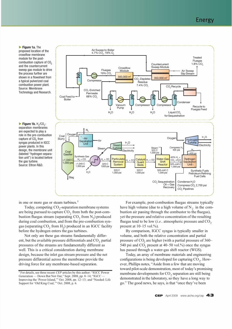
Figure 1a. Theproposed location of thecrossflow membrane
module for the post-combustion capture of CO
2
and the countercurrentsweep gas module to drivethe process further areshown in a flowsheet froma typical pulverized coalcombustion power plant.Source: MembraneTechnology and Research.
Figure 1b. H2 /CO
2-
separation membranesare expected to play arole in the pre-combustioncapture of CO
2 from
syngas produced in IGCCpower plants. In thisdesign, the membrane unit(labeled “hydrogen separa-tion unit”) is located beforethe gas turbine.Source: Eltron R&D.
Oxygen
Oxygen Air
SteamElectricity
H2O
Electricity
H2O
H2O
H2
N2
CoalSlurry
Slag
Synthesis GasH
2 + CO H
2 + CO
40% H2 +
CO2 +H
2O
CoalGasifier
>1,040˚C1,000 psi >1,040̊ C
1,000 psi
<400 psi
320̊ C1000 psi
320̊ C
1,000 psi
320̊ C
1,000 psi
Steam320̊ C
1,000 psi
Compress H2
435 psi
320–440̊ C
1,000 psi
320–440̊ C1,000 psi
ParticulateRemovalSystem
SteamTurbine
HydrogenTurbine
CatalystGuardBeds
CO2 Sequestration
Oil + GasRecovery
Synthetic Fuels
Petroleum RefiningFuel Cells
Condense H2O
Compress CO2 2,700 psi
CO2 Pipelines
Water-GasShift
Reactor
HydrogenSeparation
Unit
AirSeparation
Unit
H2 + CO H
2 + CO
† For details, see three recent CEP articles by this author: “IGCC PowerGeneration — Down But Not Out,” Sept. 2008, pp. 8–14; “IGCC —Improving the ‘Power Island,’” Oct. 2008, pp. 12–13; and “Needed: LifeSupport for ‘Old King Coal,’” Oct. 2008, p. 6.
8/11/2019 CO2 Capture Membrane Systems
http://slidepdf.com/reader/full/co2-capture-membrane-systems 3/6
44 www.aiche.org/cep April 2009 CEP
Energy
adequately proven, these systems should scale up pretty
easily (because membrane scaleup tends to be linear), so thisshould help to speed the eventual widespread commercial-
scale use of membrane systems for CO2 capture.”
A pressing need
“In terms of technical feasibility, the use of membrane
systems for the pre-combustion removal of CO2 from
syngas in IGCC facilities is the most promising because of
the higher pressures and concentrations that are available,”
says John Marano, president of JM Energy Consulting,
Inc. (Gibsonia, PA). However, Ciferno of NETL notes that
“the need for a membrane-based retrofit option for post-
combustion CO2
capture from coal-fired power plants is
perhaps even more urgent because of the severe operating
and economic penalties imposed on the power plant by
existing solvent-based absorption options.”
In general, the U.S. Dept. of Energy (DOE; Washing-
ton, D.C.; www.doe.gov) has set a target for CO2-capture
technologies to achieve 90% CO2 capture, incur less than
20% parasitic energy losses, and increase the overall cost
of electricity (COE, a metric that is a function of the energy
required for capture and the capital cost of the capture
equipment) by no more than 10% for IGCC plants and by
no more than 35% for conventional coal-fired plants.
Studies indicate that current absorption-based processes
(i.e., the Selexol, Rectisol and monoethanolamine [MEA] processes) result in 10–30% parasitic energy losses,
35–110% increased capital costs, and 30–80% increased
COE. “The hope within the engineering community is that
membrane-based approaches will eventually be able to
significantly reduce the cost of CO2 capture compared to
these existing options,” says Ciferno.
Solvent-based processes have numerous heat exchange
requirements to cool the streams for treatment and to
reheat them to meet temperature needs further downstream,
says EPRI’s Phillips. “By comparison, there are many
potential thermodynamic advantages and implied capital
cost savings when a membrane system is able to handlesyngas right out of the solids filter or WGS reactor and
carry out the separation at, say, 300°C, to separate the CO2
and send the H2 straight to the gas turbine at the needed
temperature,” he adds.
Using a sweep gas to improve separation
To improve membrane-separation ef ficiency in both
pre-combustion and post-combustion settings, several
membrane designers are investigating the use of a sweep
gas on the downstream (low-pressure) permeate side of the
membrane. Nitrogen is the sweep gas of choice for IGCC
applications, while coal-fired power plants are more likely
to use a slipstream of compressed combustion air. In an IGCC facility, the ability to use a nitrogen stream
to continuously remove product hydrogen from the perme-
ate side of the membrane — a concept devised by NETL
— helps to continuously boost the differential pressure
(which creates a larger driving force) across the membrane,
explains Marano. In addition, a nitrogen source is readily
available in most IGCC facilities, because the enormous
air separation units (ASUs) required to produce the needed
oxygen for oxygen-blown coal gasification also produce
large volumes of byproduct nitrogen.‡
Meanwhile, the use of a nitrogen sweep will serve
another important purpose in an IGCC facility. “Hydro-
gen not only has a lower density and completely different
flow geometries, but it has a broader flammability range
and a flame speed that is an order of magnitude higher
than hydrocarbon fuels,” explains Phillips. As a result, the
advanced gas turbines being designed to burn hydrogen
in IGCC plants are expected to require some fuel dilution
— for example, via the addition of 40–60 vol.% N2 —
because the high firing temperature of H2would otherwise
create excessive NO2 emissions.
“If you add a nitrogen sweep on the permeate side
of the H2/CO
2 separation membrane, you not only help
the membrane to function better, but you help the down-
stream turbine meet its own hydrogen-nitrogen blendingneeds and lower the flame temperature in the gas turbine,”
Phillips notes. “And, because the use of a sweep gas also
allows the pressure of the product hydrogen stream to be
kept at 350–450 psi or more, this could reduce the need for
a booster compressor ahead of the hydrogen turbine.”
For coal-fired power plants, the use of air as the sweep
gas (instead of nitrogen) is being investigated. A slip-
stream of air (which is already being produced to feed the
boiler’s pulverized-coal combustion system) sweeping
across the permeate side of the membrane would continu-
ously remove product CO2, thereby increasing the pressure
differential across the membrane and driving the CO2/N2 separation further.
Once the air/CO2 sweep mixture is returned to the com-
bustor inlet, the oxygen is burned and the small recycled
stream of CO2 in the sweep helps to bring the partial
pressure of the CO2 in the boiler fluegas up from about
14 vol.% to 19 vol.%, improving the overall membrane
separation, explains Tim Merkel, director of process R&D
at Membrane Technology and Research (MTR; Menlo
Park, CA; www.mtrinc.com).
‡ See another recent article by this author, “Oxygen and Nitrogen: On-ward and Upward,” CEP, Jan. 2009, pp. 6–10.

8/11/2019 CO2 Capture Membrane Systems
http://slidepdf.com/reader/full/co2-capture-membrane-systems 4/6
CEP April 2009 www.aiche.org/cep 45
Membrane systems for pre-combustion CO2 capture
As IGCC deployment picks up speed, advancedIGCC facilities are expected to be routinely designed for
carbon capture and storage (CCS). These state-of-the-art
IGCC+CCS processes are expected to include a water-
gas shift (WGS) reactor, in which the “unshifted” syngas
stream (CO + H2) is reacted with steam over a catalyst to
convert CO to CO2, producing a “shifted” syngas composed
primarily of hydrogen and CO2 (shown in Figure 1b).
This shift reaction serves two purposes. First, it yields
an enriched hydrogen stream, which can be burned in
specialized hydrogen turbines in the IGCC facility’s
combined-cycle power plant. Second, it effectively con-
centrates the carbon in the syngas into an enriched CO2
stream, making CO2 capture for industrial use or enhanced
oil recovery (EOR) applications or for long-term under-
ground sequestration in a deep geological reservoir easier
and more cost-effective.
IGCC systems provide an ideal environment for
membrane separation. “When a membrane-based separa-
tion system is placed downstream of the WGS reactor, the
shifted syngas not only has a higher concentration of CO2,
but the partial pressure of that CO2 is also higher, provid-
ing the needed driving force across the membrane, mini-
mizing the need for syngas compression,” says Phillips.
Specifically, syngas typically exits the gasifier at an
elevated pressure of 600–800 psi or more. After the WGSstep, the relative concentration of CO
2 in the shifted syngas
is 40–50 vol.% CO2, and its partial pressure is 240–400 psi.
This provides enormous driving force for membrane separa-
tion compared to post-combustion fluegas, which typically
contains just 15 vol.% CO2 and is at atmospheric pressure.
For any CO2-capture scenario, the ability to retain as
much pressure as possible through the system is key not
only to drive the separation, but also to meet the down-
stream pressure requirements. For instance, pipeline and
subsurface sequestration require the CO2 to be at pressures
near 2,200 psi so that the CO2 gas behaves like a supercrit-
ical fluid and takes up less space underground. Similarly,after syngas separation, the hydrogen stream will need
to remain at a minimum pressure of 350–450 psi to meet
downstream turbine requirements.
Eltron Research and Development (Boulder, CO;
www.eltronresearch.com) has developed a three-layer
H2/CO
2 separation membrane that combines a proprietary,
dense-phase metallic hydrogen-transport membrane with
two catalyst layers, each just 300 nm thick. On the feed side
of the membrane (which receives inlet syngas at 450–1,000
psi), the first catalyst layer dissociates the hydrogen gas into
hydrogen atoms. On the permeate side, the other catalyst
layer promotes the reassociation of the hydrogen atoms so
that hydrogen gas exits the unit at pressures up to 400 psi.“Based on this atomic transport of hydrogen, this novel
membrane design provides enhanced selectivity for hydro-
gen permeation — in the range of five or six nines purity,”
adds Doug Jack, vice president of technology for Eltron.
DOE has set a 2010 target for pre-combustion CO2/H
2
membrane-separation systems to achieve hydrogen flux
rates of 200 std. ft3/h per square foot of membrane area
(scfh/ft2) and a 2015 target of 300 scfh/ft2. Jack notes that
Eltron’s three-layer membrane/catalyst configuration has
already demonstrated hydrogen flux rates of 450 scfh/ft2.
To date, a pilot-scale unit of the Eltron process —
which will lead to a bundled shell-and-tube vessel design
(Figure 2) — has produced 5 lb/d of hydrogen as the prod-
uct, and 85 lb/d of CO2 as the retentate, under anticipated
operating conditions. The company is seeking to partner
with an existing coal-fired syngas facility to perform the
next phase of scaleup, which will demonstrate a unit that
produces 220 lb/d of hydrogen (1.9 tons/d of CO2) using a
slipstream of syngas from an actual coal gasifier.
When syngas is passed through the Eltron membrane
system, roughly 95% of the hydrogen passes through as the
product or permeate stream, while the CO2 is captured on
the upstream side of the membrane as the retentate stream.
Because the CO2 doesn’t pass through the membrane, it
doesn’t experience a pressure drop, and “this helps the CO2 stream to remain close to the gasifier pressure, minimizing
the capital costs and energy requirements to recompress
millions of tons of CO2,” says Jack.
Meanwhile, using the concept of process intensifica-
Figure 2. Developers of ceramic and metallic membranes for CO2
capture are working with shell-and-tube vessel designs, such as this Eltronprototype metallic membrane system, for the pre-combustion separation ofCO
2 and hydrogen in IGCC syngas. Source: Eltron R&D.
W a t e r - G a
s S h i f t M
i x t u r e E n t r
a n c e
Hydrogen
Exit C o n c
e n t r a t e d C
O 2 E x h
a u s t
Closed End of Tubes
Membrane Tubes
8/11/2019 CO2 Capture Membrane Systems
http://slidepdf.com/reader/full/co2-capture-membrane-systems 5/6
46 www.aiche.org/cep April 2009 CEP
Energy
tion, Eltron has also developed a specialized WGS reactor
that combines the company’s dense-phase hydrogen-trans-
port membrane within the WGS reactor. This hybrid design
accomplishes two key objectives — it separates the hydro-
gen from CO2 in the shifted syngas stream, and it drives
the shift reaction further with the continuous removal
of the product hydrogen as the WGS reaction proceeds.
“This enables simultaneous hydrogen production and CO2
capture from a single reactor vessel,” says Jack. “Continu-ously pulling out the primary product hydrogen to drive
the reaction further is the only way to beat the equilibrium
constraints of the water-gas shift reactor.” Demonstrated at
bench scale to date, the unit is ready for the next scale of
demonstration, once an industrial partner emerges.
Membrane systems for post-CO2 capture
The challenge of implementing membrane-based
separation systems becomes even more acute for coal-fired
power plants due to the nature of the fluegas stream. “Post-
combustion membrane capture wasn’t even in the DOE
project R&D portfolio until the last two or three years. Butthe need to retrofit existing coal-fired power plants is a big
driver today,” says Ciferno of NETL.
“Post-combustion systems that rely on amine-based
separation of CO2 are already taking a pretty big hit, in
terms of the cost penalty of the prevailing technique. So
that provides a pretty big incentive for membrane design-
ers to develop a system that can cost-effectively be retrofit
to existing power plants,” he adds.
To get around this fundamental engineering
challenge of handling a large-volume, low-pressure, dilute
stream, many of today’s membrane developers have been
pursuing advanced membrane materials that provide
increasedfl
ux rates and selectivity for CO2. (Mem- brane materials are discussed in the white paper cited
in the footnote on p. 42). Many are also designing
their post-combustion membrane systems to pull a
slight vacuum on the permeate side (as this is less
costly than compressing the large volume of dilute
fluegas at the inlet side), and pursuing designs that in-
corporate a sweep gas on the permeate side (discussed
earlier) to increase the pressure differential across the
membrane (shown in Figure 1a).
MTR has developed a new CO2-selective
polymeric membrane material and module — dubbed
the MTR Polaris membrane — that provides higher
CO2 permeance for post-combustion fluegas applica-
tions than existing polymeric membranes, says Merkel.
Permeance is a measure of pressure-normalized flux,
an indication of how much gas is actually flowing
acrossthe membrane per unit of pressure differential.
Permeance equals permeability (an intrinsic material
property) divided by the thickness of the selective layer, and
is expressed in gas permeance units (GPU), with 1 GPU =
10-6 cm3(STP)/cm2(scmHg) = 3.3 × 10⁻¹ mol/(m2-s-Pa).
With cellulose acetate membranes (the most common
material used to remove CO2 from methane during natural
gas processing), flux rates “are so low, you’d need too much
membrane surface area to effectively treat power plant flue-gas, so this material is not economical for power plant
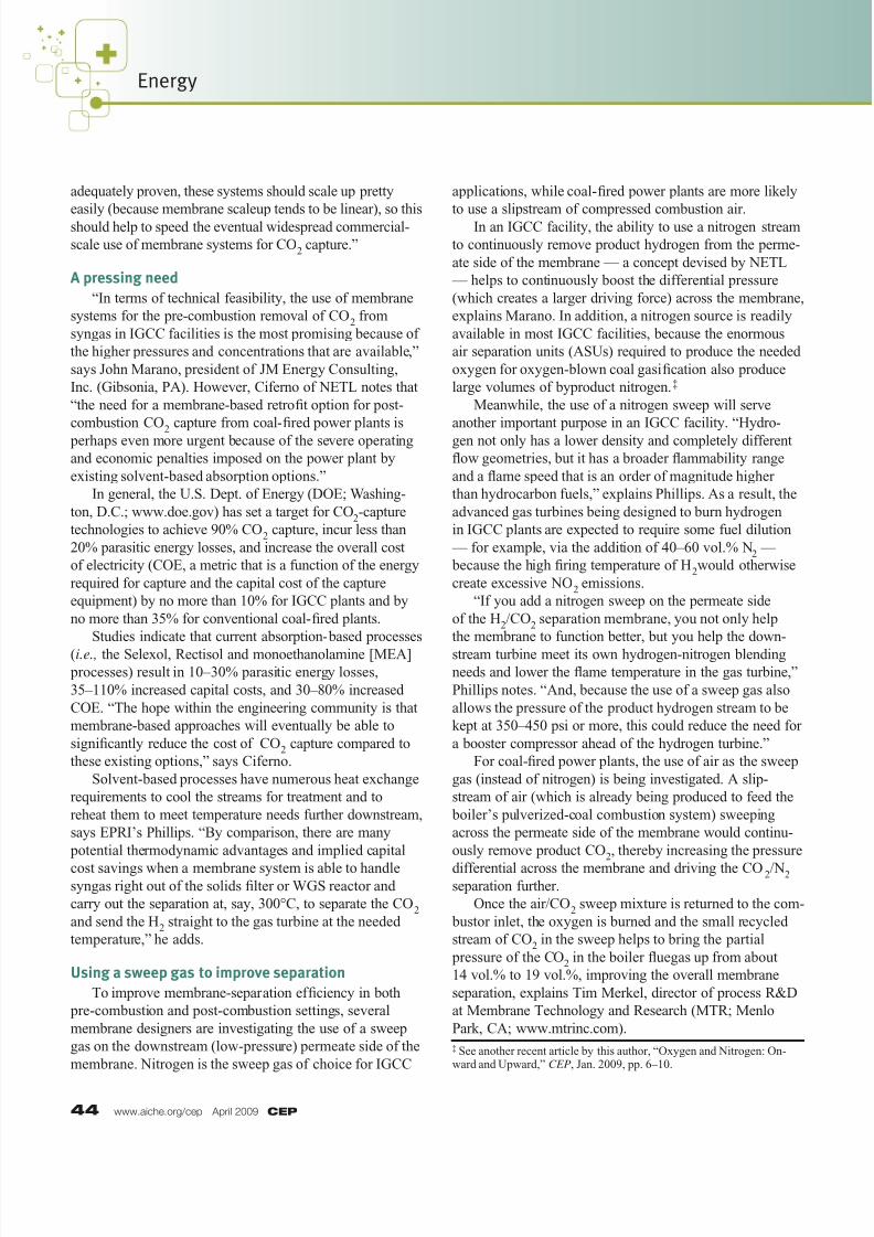
applications,” Merkel says. By comparison, the spiral-
wound MTR Polaris membrane (Figure 3) developed to
separate CO2 from nonpolar gases (such as methane or
nitrogen) has a CO2 permeance rate that is 10 times higher
than that of cellulose acetate (1,000 GPU versus 100 GPU).
Because the MTR Polaris membranes are ten times
more permeable to CO2 than conventional materials (which
reduces the required membrane area and capital costs), and
use a slipstream of combustion air as a sweep gas, “we’ve
been able to develop a system with reasonable membrane
area requirements, reduced energy requirements, andreasonable capture costs for fluegas,” says Merkel.
To date, the MTR Polaris membrane has been dem-
onstrated in 8-in.-dia. (incorporating 20 m2 of membrane
area) and 12-in.-dia. (50 m2) modules in the field treating
natural gas. In late 2009, the company will be working
with the Arizona Public Service Co. (APS) Cholla power
plant (Joseph City, AZ) to demonstrate a larger system that
will handle actual coal-fired fluegas and produce 1 ton/d
of CO2. A commercial-scale system for a 600-MW power
plant will eventually produce 10,000 ton/d of CO2,
says Merkel. To date, the air sweep system has been
Figure 3. The spiral-wound MTR Polaris membrane system, which separatesCO
2 from nonpolar gases such as nitrogen or methane, is being developed for the
post-combustion capture of CO2 from conventional power plants and for natural gas
processing applications. Source: MTR.
SelectiveLayer*
Residue
Flow
ResidueFlow
PermeateFlow
Spacer
Membrane
Spacer
Permeate Flow After Passing Through
Membrane
MicroporousLayer*
SupportWeb*
Feed Flow
Module Housing
Feed Flow
Feed Flow
*Not to Scale

8/11/2019 CO2 Capture Membrane Systems
http://slidepdf.com/reader/full/co2-capture-membrane-systems 6/6
CEP April 2009 www.aiche.org/cep 47
demonstrated at bench scale; larger-scale demonstration
will take place at the APS Cholla site.
Facilitated transport membranes
Another class of membranes — facilitated transport
membranes, or FTMs —“have been studied for over 40
years, and show tantalizingly good performance under
ideal conditions,” says Merkel. “Unfortunately, they
have never been used commercially, primarily because of
carrier-instability problems.”
Today, Carbozyme, Inc. (Monmouth Junction, N.J.;
www.carbozyme.us) is working to improve the basic FTM
concept for CO2 capture from post-combustion fluegas.
Structurally, Carbozyme’s novel design consists of a series
of hollow polymeric membrane fi bers that are woven
into a flat fabric, which provides a controlled mechanism
for maintaining a flat liquid film (Figure 4). The liquid is
trapped between the individual membrane strands in each
woven sheet, and between the sheets that are layered and
spiral-wound to fit into the process vessel. Alternating rows
of the hollow polypropylene fi bers in the fabric carry either
the feed gas or the sweep gas. “This design combines
membrane-based diffusion and liquid absorption for better
overall separation,” says Michael Trachtenberg, chairman,
CEO and CTO of Carbozyme.
Some earlier FTM designs rely on amines (which are
corrosive and toxic) as the liquid phase to bind to CO2 and promote absorption and desorption of CO
2 across the
membrane-liquid interfaces in a single device. By contrast,
Carbozyme’s FTM system relies on saltwater instead.
“Our spiral-wound units provide massive membrane
surface area, helping to minimize residence time, and the
gas runs axially in the bore of the hollow fi bers, so there’s
not much pressure drop across the system,” says Trachten- berg. “As CO2 diffuses across the microporous, hydro-
philic hollow fi bers, it is catalyzed by an enzyme (carbonic
anhydrase, or CA) that is immobilized at the gas-liquid
interface. CA converts CO2 to bicarbonate at the feed side,
and following diffusion of the bicarbonate across a very
thin film, the reverse reaction occurs via a second layer of
CA at a second surface,” he explains (Figure 5).
CA is a very ef ficient catalyst for turning CO2 into
bicarbonate, whose solubility in water is several orders
of magnitude higher than that of dissolved CO2, and this
enables high separation ef ficiencies, explains Trachten-
berg. In addition, no heating or cooling of the inlet stream
is required (fluegas enters the system at the adiabatic
temperature of 52°C), and a mild vacuum pulled on the
downstream side helps to increase the pressure differential
across the membrane fi bers. “The permeate stream has
roughly 50 vol.% CO2 with a comparable amount of water
vapor, and when the water is taken out, the dry permeate
stream is about 95 vol.% CO2,” he says.
To date, a demonstration-scale unit with 0.5 m2 of
membrane surface area has operated for 250 h using artifi-
cial gas mixtures that simulate coal fluegas. The company
is gearing up for a 40-m2 demonstration system slated for
startup later this year, which it hopes to operate for 2,000
hours using actual coal-combustion fluegas at DOE’s En-ergy and Environmental Research Center at the Univ.
of North Dakota.
As competing membrane materials and system configu-
rations continue to mature, the engineering community is
confident that this technology will provide a more cost-
effective option for CO2 capture compared to the use of
solvent-based absorption, which is the prevailing technol-
ogy option available today.
Figure 4. Many polymeric membranes used for gas-gas separationrely on a vessel containing bundled strands of hollow-fiber membranes.In the Carbozyme FTM system, the strands are woven into a fabric,which is then spiral-wound and put into the process vessel. Thismaximizes the overall surface area and enables the liquid film(described in text) to be supported throughout the entire device.Source: Carbozyme.
Figure 5. In the Carbozyme system, the enzyme carbonic anhydrase (CA),immobilized at the gas-liquid interface, acts as an effective catalyst to convertCO
2 to bicarbonate at the feed side (and to reverse the reaction later) to maxi-
mize the separation of CO2 from coal fluegas. Source: Carbozyme.
CA =Carbonic Anhydrase
DIC =DissolvedInorganicCarbon
CO2 = 15%
CO2
CO2
O2
N2
CO2 = 1.5%
CO2 ≈ 48%
H2O ≈
48%
CO2 = 0%
Feed Permeate
SweepRetentate
F l u e g a s
CA CA
DIC
CLM
S t a ck G a s
R
i ch
C O2
V a c u um
O2
N2
H2O
vapor
CEP