co tolerance of pt and ptsn intermetallic … (rgo) supports and were characterized by a combination...
TRANSCRIPT

DaltonTransactions
PAPER
Cite this: Dalton Trans., 2015, 44, 977
Received 20th August 2014,Accepted 4th November 2014
DOI: 10.1039/c4dt02544j
www.rsc.org/dalton
CO tolerance of Pt and PtSn intermetallicelectrocatalysts on synthetically modifiedreduced graphene oxide supports†
Christopher M. Sims, Audaldo A. Ponce,‡ Karen J. Gaskell and Bryan W. Eichhorn*
Pt and PtSn intermetallic nanoparticle (NP) catalysts were grown directly on various reduced graphene
oxide (rGO) supports and were characterized by a combination of X-ray photoelectron spectroscopic
(XPS), Raman microscopy, transmission electron microscopy (TEM), and powder X-ray diffraction (XRD)
studies. Electrochemical CO stripping and rotating disk electrochemical (RDE) experiments showed the four
rGO-PtSn catalysts to be superior to the four rGO-Pt catalysts for CO and CO–H2 electrooxidation in acidic
solutions regardless of the rGO support, in agreement with earlier reports on PtSn NP electrocatalysts. For
the four rGO-Pt catalysts, the rGO support causes a 70 mV spread in CO oxidation peak potential (ΔEpeak)and a 200 mV spread in CO–H2 electrooxidation onset. The more oxygenated graphenes show the lowest
CO oxidation potentials and the best CO tolerance. For the four rGO-PtSn intermetallic catalysts, a
∼160 mV spread in CO–H2 electrooxidation onset is observed. With the exception of the nitrogen-doped
graphene (NGO), a similar trend in enhanced CO electrooxidation properties with increasing oxygen
content in the rGO support is observed. The NGO-PtSn electrocatalyst was superior to the other rGO-PtSn
catalysts and showed the largest improvement in CO tolerance relative to the pure Pt system. The origin of
this enhancement appears to stem from the unique rGO-PtSn support interaction in this system. These
results are discussed in the context of recent theoretical and experimental studies in the literature.
Introduction
As a carbon-based support material for nanoparticle (NP)electrocatalysts, graphene is thought to be advantageous overtraditional carbon black (CB), due to its large surface area,1
high electronic conductivity,2 and relative ease of production.3,4
While industrial-scale production of pristine graphene sheets iscurrently impractical, reduced graphene oxides (rGO) are avail-able in large quantities and have been subjected to manystudies. In contrast to pristine graphene, rGOs can containseveral kinds of functional groups, heteroatoms and defects.Many pathways have been developed for synthesizing rGOs,including one-step thermal exfoliation/reduction,5,6 high temp-erature reduction in hydrogen atmosphere,7 wet chemicalreductions,8–10 and various combinations of these
techniques.11–13 Different synthetic methods create differentfunctional groups that alter the physical and electronic pro-perties relative to pristine graphene.5,6,8,14–20 The defects andfunctional groups in the rGOs alter the interactions between theNP and support and potentially affect the catalytic activity of asystem. For example, recent thermal studies have shown thatrGO-supported iron-based NP catalysts had markedly better per-formance in syn-gas conversions relative to the same iron-basedNP catalysts on carbon nanotubes.21
While many electrochemical studies have been conductedon rGO-supported metal NP catalysts,22–37 the influence ofrGO on the electrocatalytic activity of NPs is not well under-stood. In the context of electrooxidation of hydrogen in thepresence of CO impurities (i.e. CO tolerance), previousstudies28,36,38 have suggested that rGO-Pt NPs feature improvedactivity relative to CB-Pt catalysts due to Pt electronic structuremodification as a result of strong Pt–graphene interactions.The magnitude of this metal-support interaction is thought tobe dependent on the amount and types of chemical defectswithin the graphene structure.38–40 Since the chemistry offunctionalizing graphene has advanced significantly in recentyears, the ability to tune these metal-support interactionsthrough chemical modification of graphene is potentiallypowerful. Metal-support interactions between NPs and
†Electronic supplementary information (ESI) available: XPS and Raman spectraof heat-treated rGOs, Nitrogen 1s XPS spectra of NGO before and after heat-treat-ment, additional TEM images of rGO-supported Pt and PtSn intermetallic NPs,EDS analysis of rGO-supported PtSn intermetallic NPs. See DOI: 10.1039/c4dt02544j‡Present address: Department of Materials Science and Engineering, Universityof Maryland, College Park, MD 20742, USA.
Department of Chemistry and Biochemistry, University of Maryland, College Park,
MD 20742, USA. E-mail: [email protected]
This journal is © The Royal Society of Chemistry 2015 Dalton Trans., 2015, 44, 977–987 | 977
Publ
ishe
d on
04
Nov
embe
r 20
14. D
ownl
oade
d by
Pen
nsyl
vani
a St
ate
Uni
vers
ity o
n 30
/05/
2015
21:
53:3
2.
View Article OnlineView Journal | View Issue

inorganic supports are well known to have significant influ-ences on catalytic activities, but are not tunable in the sameway that a graphene system can be modified.41–43 This researchaims to evaluate the influence of different types of modifiedgraphene on electrocatalytic activity with the ultimate goal ofdeveloping predictability and control in the design of new elec-trocatalyst systems.
To evaluate the metal-support interactions between modi-fied graphene and metallic NP catalysts, we describe the fullcharacterization of four different rGOs and their use in prepar-ing rGO-supported Pt and PtSn electrocatalysts catalysts. Theseelectrocatalysts were evaluated for their CO electrooxidationand CO–H2 electrooxidation activities. Our studies show thatthe nature of the rGO support material affects the resulting Ptor PtSn NP size. In the case of nitrogen-doped rGOs, an anom-alous metal support interaction was found that caused amarked difference in the behavior of the Pt and PtSn systemsfor CO–H2 electrooxidation.
Experimental sectionMaterials
Vor-X graphene powder (FGS, C : O ratio = 22) was provided byVorbeck Materials. Single layer graphene (SLG, powder) andsingle layer graphene oxide (GO, flakes) were purchased fromACS Material. Platinum acetylacetonate (Pt(acac)2, 97%), tinchloride (SnCl4, 99%), sodium triethylborohydride solution(NaBEt3H, 1.0 M in toluene), sodium borohydride (NaBH4,98%), hydrazine monohydrate (H2NNH2, 98%), 1-octadecene(90%), and acetone (99.5%) were purchased from Aldrich.Methanol (MeOH, 99.8%) was purchased from VWR. Tetra-hydrofuran (THF, 99%) was purchased from Mallinckrodt. Iso-propanol (iPrOH, 99%) was purchased from Pharmco-AAPER.Sulfuric acid (H2SO4, 96.4%) was purchased from Fisher.Nafion® (5%) solution was purchased from Fluka. E-TEKPt (30% HP Pt on Vulcan® XC-72) was purchased from BASF.Ultra-pure water was obtained from deionized water using aMillipore Academic Milli-Q A10 purifier system. All materialswere used as received without further purification.
Preparation of borohydride-reduced graphene oxide (BGO)
Typically, GO (100 mg) was dissolved in ultra-pure water(40 mL) through sonication in a glass beaker and then trans-ferred into a 100 mL round-bottomed flask. NaBH4 (1 g,0.026 mol) was added to the solution, which was then heatedto 80 °C for 24 h. After cooling to room temperature, the blackprecipitate was separated by filtration, washed with copiousamounts of water, air-dried overnight and dried under reducedpressure for 24 h.
Preparation of hydrazine-reduced graphene oxide (NGO)
The same procedure as above was utilized, except H2NNH2
(1 mL, 0.02 mol) was used instead of NaBH4. All other stepswere identical.
Synthesis of rGO-supported PtSn intermetallic NPs
In a typical synthesis, rGO (13.3 mg) was mixed with 1-octa-decene (10 mL) in a glass vial and sonicated for 2 h in a soni-cation bath. The resultant mixture was then added to aschlenk flask and degassed at 80 °C while stirring. Oncedegassed, N2 was introduced and the temperature wasincreased to 200 °C. In a separate vial, Pt(acac)2 (10.0 mg,0.025 mmol Pt) was dissolved in 1-octadecene (1 mL),degassed, and placed under N2. SnCl4 (3 μL, 0.025 mmol Sn)was then added to the Pt precursor solution while stirring.NaBEt3H solution (2 mL, 1.0 M) was injected into the rGO dis-persion, immediately followed by the injection of the PtSn pre-cursor solution. All injections were performed using N2-purgedsyringes. The reaction mixture was returned to 200 °C for60 min before the heating source was removed. The flask wasallowed to cool down to room temperature before the blackslurry was transferred to a 50 mL conical centrifuge tube.MeOH (2 mL) and acetone (20 mL) were added to the tube andthe resultant mixture was sonicated for 10 min. The tube wasthen centrifuged at 6000 rpm for 15 min. The supernatant wasdiscarded and the black solid was mixed with ultra-pure water(2 mL) and acetone (10 mL) and sonicated for 10 min. Theresultant mixture was divided amongst several 1.5 mL conicalcentrifuge tubes and centrifuged at 13 000 rpm for 2 min. Thesupernatant of each tube was discarded and the black solidswere mixed with 1 mL acetone, vortexed, then centrifuged at13 000 rpm for 2 min. The acetone washing process wasrepeated five times. The black solid was then dried undervacuum for 60 min. The dried solid was placed in a ceramicboat, which was introduced into a quartz glass tube. The tubewas heated in a horizontal solid tube furnace (ThermolyneF21135, Thermo Scientific) at 400 °C for 120 min under a5% H2/95% Ar atmosphere with a flow rate of 90 cc min−1.
Synthesis of rGO-supported Pt NPs
The same procedure as above was utilized, except SnCl4 wasabsent and the amount of Pt(acac)2 was increased to maintainthe same weight percent loading of metal on rGO (11.5 mg,0.029 mmol Pt). All other steps were identical.
Sample characterization
Raman spectroscopy data were collected on a Horiba YvonLabRam ARAMIS Raman microscope using a ∼1 mW, 532 nmwavelength laser source. The rGO samples were pressed on aglass slide for analysis. X-ray photoelectron spectroscopy (XPS)data were collected on a Kratos Axis 165 X-ray photoelectronspectrometer operating in the hybrid mode using Al mono-chromatic radiation (1486.6 eV) at 280 W. Charge neutralizationwas used to minimize sample charging. Binding energies werecalibrated with respect to the C 1s peak at 284.8 eV. Casa XPSsoftware was used for data analysis peak fitting; all peaks werefit after subtraction of a Shirley background. An ad hoc asym-metric peak shape (A(0.41, 0.36, 70)GL(50)) was used to fit theprimary graphitic carbon peak for all the rGO samples. Theπ→π* shake-up satellites were fitted to have a full width at half
Paper Dalton Transactions
978 | Dalton Trans., 2015, 44, 977–987 This journal is © The Royal Society of Chemistry 2015
Publ
ishe
d on
04
Nov
embe
r 20
14. D
ownl
oade
d by
Pen
nsyl
vani
a St
ate
Uni
vers
ity o
n 30
/05/
2015
21:
53:3
2.
View Article Online

maximum (FWHM) value of 3.5 at maximum. All other peakswere fixed to have the same FWHM for each sample. Peak posi-tions for C–N, C–O, CvO, COOH, and the π→π* shake-up satel-lites were fixed relative to the graphitic peak with separations of0.9, 1.7, 3.0, 4.3, 6.4 eV respectively. Powder X-ray diffraction(XRD) patterns were obtained on a Bruker C2 Discover diffract-ometer equipped with a VÅNTEC-500 detector using a mono-chromatic Cu Kα radiation source biased at 40 kV and 40 mA.The rGO-supported NP powders were pressed on a glass slidefor analysis. Transmission electron microscope (TEM) imageswere obtained on a JEM 2100F Field Emission TEM operating at200 kV. Energy-dispersive X-ray spectroscopy (EDS) data werecollected on the same TEM operating in STEM mode. The rGO-supported NP powders were dispersed in THF, and a 6 μLaliquot of the resulting dispersion was drop cast on the TEMgrids. The TEM grids used were lacey carbon-coated Cu grids(Cu-400LC, Pacific Grid Tech).
Electrochemical analysis
iPrOH (159.2 mL), ultra-pure water (40.0 mL) and Nafion®solution (0.80 mL, 5%) were mixed and stored as a stock solu-tion. The catalyst ink was prepared by mixing the supportedNP powder with the above stock solution such that the concen-tration was 1.0 mg mL−1 of powder in solution. The resultantmixture was then sonicated for 120 min. The catalyst ink(20 μL) was cast on a glassy carbon (GC) electrode (Pine Instru-ments, 5.0 mm diameter) using a micropipette and allowed todry in air overnight while covered. Electrochemical studieswere performed on a potentiostat (Autolab PGSTAT30) with astandard rotating electrode electrochemical cell. The rotatingGC disk electrode with dried catalyst ink on its surface wasused as the working electrode. Pt wire was used as the counterelectrode and a saturated calomel electrode (SCE) was used asthe reference electrode. All potentials were recorded withrespect to the SCE. H2SO4 in ultra-pure water (0.5 M) was usedas the electrolyte. To obtain the CO stripping curves, the cata-lyst was saturated with CO by bubbling CO in the electrolytefor 20 min with the electrode potential held at −0.2 V vs. SCE,followed by Ar-purging for 40 min. Two consecutive potentialscans (20 mV s−1) were then run to obtain the CO strippingand baseline curves. To obtain polarization curves for theelectrooxidation of CO-contaminated H2, the electrolyte wasbubbled with a 1000 ppm CO–balance H2 gas mixture for60 min with the electrode potential held at −0.20 V vs. SCE,followed by a potential scan (1 mV s−1) at a rotation rate of1600 rpm.
Results
A series of rGO-supported Pt and PtSn nanoparticle catalystswere prepared from both commercial and synthetic rGOs toprobe the metal-support influences on catalytic CO–H2 electro-oxidation. We compared Pt and PtSn catalysts because they areboth well known hydrogen electrooxidation catalysts and theirrespective abilities to mitigate CO-poisoning effects are well
understood.44–51 By using the same catalysts on different rGOsupports, the relative shifts in H2 oxidation onset with a well-defined CO impurity can be used as a measure of catalyticmodification. To fully evaluate the series of rGOs, we used twocommercial rGOs, known as functionalized graphene sheets(FGS) by Vorbeck Materials and single layer graphene (SLG) byACS Material. In addition, we prepared two synthetic rGOs byreducing a synthetic graphene oxide (GO) with either boro-hydride or hydrazine. The hydrazine reduction method isknown to induce pyrazole-type N-doping at the edges of theresulting graphene sheets whereas borohydride reductionsgive “pure” graphene without B or N doping.8,14,15,20 Thesematerials are denoted as NGO (N-doped reduced grapheneoxide) and BGO (borohydride-reduced graphene oxide),respectively.
XPS (Fig. 1) and Raman microscopy studies (Fig. 2) showthat the four rGOs have different degrees of reduction (i.e. gra-phene-like character) and a range of functional groups. Fromthese data, the degree of graphitic-like character was evaluatedusing three different criteria: (1) the concentration of func-tional groups and defects from XPS data, (2) the FWHM valueof the graphitic carbon C 1s peak, and (3) the degree of struc-tural disorder through a comparison of the D and G peakintensities obtained from the Raman spectra. The normalizedC 1s XPS spectra of the rGOs are shown in Fig. 1 and the dataare summarized in Table 1. The comparative structural andspectroscopic data are summarized in Table 2.
The FGS, BGO, and NGO XPS C 1s spectra are very similar,featuring the expected intense peaks at 284.8 eV associatedwith graphitic type carbon (Fig. 1). While all of the rGOs haveshoulders at higher binding energies due to various functionalgroups, the C–O peak for the SLG material is the most pro-nounced (Fig. 1b). Previous studies8,11,13,14,52,53 have shownthat hydrazine and borohydride reduction methods leave someunreacted carboxyl and hydroxyl groups, which is consistentwith the small C–O, C(O)O and CvO peaks observed in ourstudies. The NGO spectrum also features a C–N peak consist-ent with the incorporation of nitrogen into the graphene struc-ture.13,15,54 The relative concentration of functional groups canbe assessed by calculating the area ratio (Cg/Cf ) of graphitic-type carbon, including π→π* shake-up satellites (Cg) to totalcarbon associated with the functional groups (Cf ). ExcludingNGO, these data suggest that SLG is the most oxygenated, con-taining a large concentration of C–O moieties. FGS containsthe fewest oxygen functionalities, with BGO intermediatebetween the two. After heat-treatment in H2 atmosphere, thereis a slight decrease in the C–O peaks for the SLG and BGOsamples (Fig. S1†). Accordingly, the Cg/Cf value for each rGOsample increases (less functional groups) with the exception ofFGS (Table S1†). Both observations are most likely due to areduction of some hydroxyl groups during the H2 atmosphereheat-treatment step.7
In addition to the oxygen-containing functional groupsdescribed above, NGO also contains 3.1% nitrogen resulting in7.9% carbon-based C–N functional groups (Table 1). The N 1sspectrum of the NGO (Fig. S3†) shows three types of nitrogen-
Dalton Transactions Paper
This journal is © The Royal Society of Chemistry 2015 Dalton Trans., 2015, 44, 977–987 | 979
Publ
ishe
d on
04
Nov
embe
r 20
14. D
ownl
oade
d by
Pen
nsyl
vani
a St
ate
Uni
vers
ity o
n 30
/05/
2015
21:
53:3
2.
View Article Online
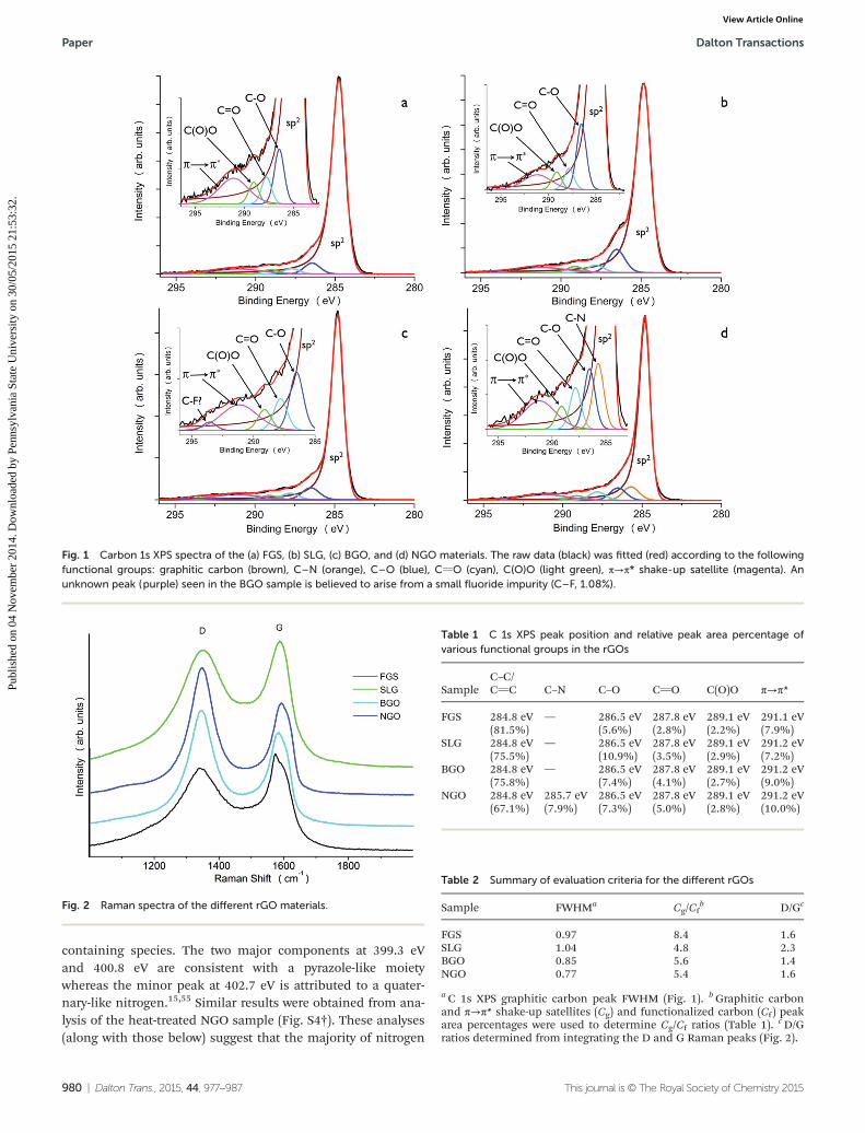
containing species. The two major components at 399.3 eVand 400.8 eV are consistent with a pyrazole-like moietywhereas the minor peak at 402.7 eV is attributed to a quater-nary-like nitrogen.15,55 Similar results were obtained from ana-lysis of the heat-treated NGO sample (Fig. S4†). These analyses(along with those below) suggest that the majority of nitrogen
Fig. 1 Carbon 1s XPS spectra of the (a) FGS, (b) SLG, (c) BGO, and (d) NGO materials. The raw data (black) was fitted (red) according to the followingfunctional groups: graphitic carbon (brown), C–N (orange), C–O (blue), CvO (cyan), C(O)O (light green), π→π* shake-up satellite (magenta). Anunknown peak (purple) seen in the BGO sample is believed to arise from a small fluoride impurity (C–F, 1.08%).
Fig. 2 Raman spectra of the different rGO materials.
Table 1 C 1s XPS peak position and relative peak area percentage ofvarious functional groups in the rGOs
SampleC–C/CvC C–N C–O CvO C(O)O π→π*
FGS 284.8 eV(81.5%)
— 286.5 eV(5.6%)
287.8 eV(2.8%)
289.1 eV(2.2%)
291.1 eV(7.9%)
SLG 284.8 eV(75.5%)
— 286.5 eV(10.9%)
287.8 eV(3.5%)
289.1 eV(2.9%)
291.2 eV(7.2%)
BGO 284.8 eV(75.8%)
— 286.5 eV(7.4%)
287.8 eV(4.1%)
289.1 eV(2.7%)
291.2 eV(9.0%)
NGO 284.8 eV(67.1%)
285.7 eV(7.9%)
286.5 eV(7.3%)
287.8 eV(5.0%)
289.1 eV(2.8%)
291.2 eV(10.0%)
Table 2 Summary of evaluation criteria for the different rGOs
Sample FWHMa Cg/Cfb D/Gc
FGS 0.97 8.4 1.6SLG 1.04 4.8 2.3BGO 0.85 5.6 1.4NGO 0.77 5.4 1.6
a C 1s XPS graphitic carbon peak FWHM (Fig. 1). bGraphitic carbonand π→π* shake-up satellites (Cg) and functionalized carbon (Cf) peakarea percentages were used to determine Cg/Cf ratios (Table 1). cD/Gratios determined from integrating the D and G Raman peaks (Fig. 2).
Paper Dalton Transactions
980 | Dalton Trans., 2015, 44, 977–987 This journal is © The Royal Society of Chemistry 2015
Publ
ishe
d on
04
Nov
embe
r 20
14. D
ownl
oade
d by
Pen
nsyl
vani
a St
ate
Uni
vers
ity o
n 30
/05/
2015
21:
53:3
2.
View Article Online

is conjugated within the delocalized π-system of the graphenestructure and remains in this state after high-temperatureheat-treatment.
The conductivity of the rGOs can be correlated with theFWHMs of their respective graphitic carbon peak. Previousstudies56,57 have shown that a smaller FWHM value is associ-ated with an increased degree of delocalization within therGO. Our data (Table 2) suggest that the NGO is most conduc-tive material (most graphene-like character), followed by theBGO, FGS, and SLG samples. This trend is essentially main-tained after heat-treatment, except FGS appears to have slightlymore graphene-like character than BGO after conditioning(Table S2†).
Raman spectroscopy provides a measure of structural dis-order in graphene-based materials through a comparison ofthe graphite-like peak (G peak) to the disorder peak(D peak).8,13,14,58 The disorder arises from intrinsic functionalgroups (ethers, epoxides, ketones), as well as atomic vacanciesand defects, which affect the interactions with supportednanoparticle catalysts. Fig. 2 shows the Raman spectra of therGOs, with the expected prominent D and G bands. The D/Gratios are listed in Table 2. Because the peak widths variedamong the different rGOs, we calculated the D/G ratios bycomparing the areas of the respective peaks and not the peakamplitudes. The rGOs examined here all have D/G ratios signi-ficantly greater than 1, which is similar to other graphene-likematerials prepared from the reduction of GO.14,29,54,59,60 Theseratios suggest that BGO is the least defective material, followedby FGS and NGO with identical values whereas SLG has thehighest defect concentration. After heat-treatment, all of the
rGO samples feature smaller D/G ratios, which are all veryclose to a value of 1 (Table S2†). This suggests the H2 atmos-phere heat-treatment induces some slight reduction of func-tional groups within the different rGO materials, in agreementwith the XPS analysis as seen elsewhere.61
From these combined analyses (Table 2), we summarize thegeneral characteristics of the rGOs as follows: (1) NGO is themost conductive rGO in our series and has few oxygen func-tional groups; the pyrazole-like nitrogen is presumably local-ized on the sheet edges15 and does not appear to impartlocalizing defects into the structure; (2) FGS is equal to NGO inthe level of disorder (D/G ratio) but FGS is less conductive andhas the smallest number of oxygen-containing functionalgroups. The defects are presumably due to atomic vacanciesassociated with the FGS synthetic method;5,6 (3) BGO has agreater amount of oxygen functionalities than FGS, but ismore conductive. This ordering is reversed after heat-treat-ment; (4) SLG is the most defective rGO, with a high concen-tration of oxygen-containing functional groups and disorderand the lowest conductivity in the series. Overall, BGO is themost graphene-like in character (low FWHM, low D/G ratio,low functional group concentration), whereas NGO is the mostconductive (lowest FWHM, low D/G ratio).
We prepared surfactant-free Pt and PtSn intermetallic(P63/mmc) NPs on the rGOs to evaluate the influence of themetal-support interactions. The rGO-supported PtSn inter-metallic NPs were synthesized through modifications of ourprevious methods.33,49 Specifically, Pt(acac)2 and SnCl4 wereco-reduced in 1-octadecene using NaBEt3H in the presence ofrGO at 200 °C. To transform the disordered PtSn alloy into its
Fig. 3 TEM images of heat-treated PtSn intermetallic NPs supported on (a) FGS, (b) SLG, (c) BGO, and (d) NGO. Lattice fringe images of singleparticles are inset.
Dalton Transactions Paper
This journal is © The Royal Society of Chemistry 2015 Dalton Trans., 2015, 44, 977–987 | 981
Publ
ishe
d on
04
Nov
embe
r 20
14. D
ownl
oade
d by
Pen
nsyl
vani
a St
ate
Uni
vers
ity o
n 30
/05/
2015
21:
53:3
2.
View Article Online
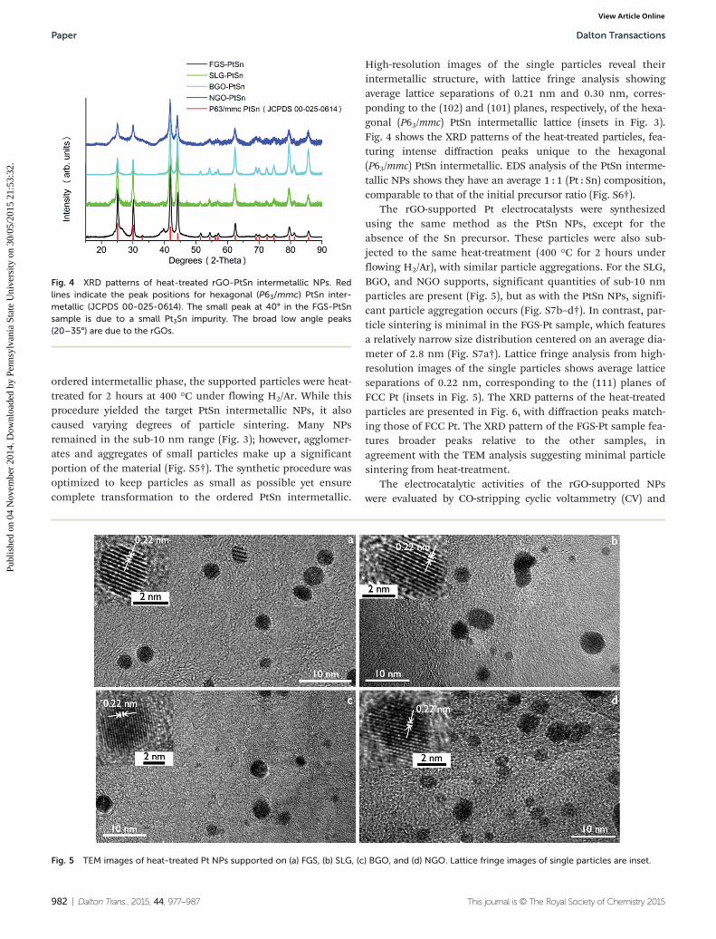
ordered intermetallic phase, the supported particles were heat-treated for 2 hours at 400 °C under flowing H2/Ar. While thisprocedure yielded the target PtSn intermetallic NPs, it alsocaused varying degrees of particle sintering. Many NPsremained in the sub-10 nm range (Fig. 3); however, agglomer-ates and aggregates of small particles make up a significantportion of the material (Fig. S5†). The synthetic procedure wasoptimized to keep particles as small as possible yet ensurecomplete transformation to the ordered PtSn intermetallic.
High-resolution images of the single particles reveal theirintermetallic structure, with lattice fringe analysis showingaverage lattice separations of 0.21 nm and 0.30 nm, corres-ponding to the (102) and (101) planes, respectively, of the hexa-gonal (P63/mmc) PtSn intermetallic lattice (insets in Fig. 3).Fig. 4 shows the XRD patterns of the heat-treated particles, fea-turing intense diffraction peaks unique to the hexagonal(P63/mmc) PtSn intermetallic. EDS analysis of the PtSn interme-tallic NPs shows they have an average 1 : 1 (Pt : Sn) composition,comparable to that of the initial precursor ratio (Fig. S6†).
The rGO-supported Pt electrocatalysts were synthesizedusing the same method as the PtSn NPs, except for theabsence of the Sn precursor. These particles were also sub-jected to the same heat-treatment (400 °C for 2 hours underflowing H2/Ar), with similar particle aggregations. For the SLG,BGO, and NGO supports, significant quantities of sub-10 nmparticles are present (Fig. 5), but as with the PtSn NPs, signifi-cant particle aggregation occurs (Fig. S7b–d†). In contrast, par-ticle sintering is minimal in the FGS-Pt sample, which featuresa relatively narrow size distribution centered on an average dia-meter of 2.8 nm (Fig. S7a†). Lattice fringe analysis from high-resolution images of the single particles shows average latticeseparations of 0.22 nm, corresponding to the (111) planes ofFCC Pt (insets in Fig. 5). The XRD patterns of the heat-treatedparticles are presented in Fig. 6, with diffraction peaks match-ing those of FCC Pt. The XRD pattern of the FGS-Pt sample fea-tures broader peaks relative to the other samples, inagreement with the TEM analysis suggesting minimal particlesintering from heat-treatment.
The electrocatalytic activities of the rGO-supported NPswere evaluated by CO-stripping cyclic voltammetry (CV) and
Fig. 4 XRD patterns of heat-treated rGO-PtSn intermetallic NPs. Redlines indicate the peak positions for hexagonal (P63/mmc) PtSn inter-metallic (JCPDS 00-025-0614). The small peak at 40° in the FGS-PtSnsample is due to a small Pt3Sn impurity. The broad low angle peaks(20–35°) are due to the rGOs.
Fig. 5 TEM images of heat-treated Pt NPs supported on (a) FGS, (b) SLG, (c) BGO, and (d) NGO. Lattice fringe images of single particles are inset.
Paper Dalton Transactions
982 | Dalton Trans., 2015, 44, 977–987 This journal is © The Royal Society of Chemistry 2015
Publ
ishe
d on
04
Nov
embe
r 20
14. D
ownl
oade
d by
Pen
nsyl
vani
a St
ate
Uni
vers
ity o
n 30
/05/
2015
21:
53:3
2.
View Article Online

rotating disk electrochemical (RDE) experiments. The resultsare benchmarked against the commercial E-TEK Pt catalyst. Allcatalysts were prepared with a 30% total metal loading byweight. Prior to the electrochemical experiments, each catalystwas subjected to 10 potential scan cycles between −0.2 V and0.8 V (vs. SCE) in 0.5 M H2SO4 saturated with Ar. Additionaldetails are found in the experimental section. The CO strip-ping curves for each of the supported Pt catalysts show thecharacteristic CO oxidation peak near 0.5 V vs. SCE (Fig. 7).62
However, the onset potentials for CO oxidation vary from0.46 V (SLG-Pt) to 0.53 V for FGS-Pt and E-TEK Pt standard.The BGO-Pt and NGO-Pt catalysts are intermediate. Fig. 8shows the RDE polarization curves for the electrooxidation of
CO–H2 mixtures (1000 ppm CO) on the Pt catalysts. The SLG-Ptand BGO-Pt show a 50 mV improvement in onset potentialsrelative to E-TEK Pt, whereas NGO-Pt and FGS-Pt are somewhatless CO tolerant than E-TEK Pt. In general, the rGO-Pt catalystsshow the expected correlation between CO stripping onset andCO–H2 electrooxidation onset where lower CO oxidation over-potentials give improved CO tolerance.
Since CO has a low affinity for binding to the PtSn surface,their CO-stripping curves are typically broad and of low inten-sity compared to their Pt counterparts (Fig. 9).44,49,63,64 Thesolid lines represent the CO stripping curves while the dashedlines are the baselines recorded after the CO stripping exper-iments. For the FGS-PtSn sample (Fig. 9), two distinct peaksare observed at 0.35 V and 0.57 V, from CO oxidation and theoxidation of surface Sn, respectively.49,50 Small Sn oxidationpeaks are present in the BGO-PtSn and NGO-PtSn samples aswell. Despite the ill-defined peak shapes, the onset potentialsfor CO oxidation can be discerned and varies from 0.08 V(NGO-PtSn) to 0.2 V (FGS-PtSn), with SLG-PtSn and BGO-PtSnintermediate.
Fig. 10 shows the polarization curves for the electrooxida-tion of CO–H2 mixtures (1000 ppm CO) on the PtSn catalystswith the E-TEK Pt reference. The rGO-PtSn polarization onsetpotentials span 160 mV and are generally 200–400 mV lowerthan their rGO-Pt counterparts. The improvement in CO toler-ance of the PtSn catalysts compared to the Pt systems is due tothe “bifunctional mechanism” of CO oxidation and is consist-ent with previous studies.49,62,65,66 The trends within therGO-PtSn catalysts also follow those of the rGO-Pt samples(SLG > BGO > FGS) with the exception of the NGO-PtSnsample, where the CO tolerance is significantly increased com-pared to its Pt counterpart. The NGO-PtSn catalyst has the bestperformance of all the rGO-Pt or rGO-PtSn catalysts and sur-passes the CO tolerance of the PtSn intermetallics supported
Fig. 6 XRD patterns of heat-treated rGO-Pt NPs. Red lines indicate thepeak positions for FCC phase Pt (JCPDS 03-065-2868). Broad peaks(20–35°, 52–56°) are due to the rGOs.
Fig. 7 CO stripping curves of rGO-Pt NP catalysts in 0.5 M H2SO4 solu-tion at 25 °C. Red line indicates E-TEK Pt catalyst as reference. Scan rate:20 mV s−1.
Fig. 8 Polarization curves for the electrooxidation of CO-contaminatedH2 (1000 ppm CO, balance H2) of rGO-Pt NP catalysts in 0.5 M H2SO4
solution. Red line indicates E-TEK Pt catalyst as reference. Curves wererecorded at 25 °C with 1 mV s−1 scan rates and 1600 rpm rotation rates.
Dalton Transactions Paper
This journal is © The Royal Society of Chemistry 2015 Dalton Trans., 2015, 44, 977–987 | 983
Publ
ishe
d on
04
Nov
embe
r 20
14. D
ownl
oade
d by
Pen
nsyl
vani
a St
ate
Uni
vers
ity o
n 30
/05/
2015
21:
53:3
2.
View Article Online

on carbon black.49 This improved CO tolerance is consistentwith the CO stripping results, where NGO-PtSn also had thelowest onset potential for CO oxidation.
Discussion
The synthetic, spectroscopic and electrochemical studiesdescribed above show that rGOs that are presumably quitesimilar in composition show a range of nanoparticle templat-ing properties and can electronically influence electrocatalyticactivity. These properties are summarized in Table 3. Twomajor tends emerge from the data.
First, the FGS support gives smaller Pt NPs with lessagglomeration and sintering after annealing relative to theother rGO supports tested. This finding is consistent with thehigh level of defects found in FGS that presumably anchor thePt seeds and NPs more tightly relative to the other rGOmaterials. Because we do not employ surfactants or disper-sants, there is always some degree of agglomeration after sin-tering, but the FGS minimizes this sintering to a large degree.The templating effect of FGS extends to other monometallicNPs,30,33 but is not apparent in the bimetallic PtSn system.The four rGO supports give similar PtSn particle sizes with nostatistical differences in diameter or agglomeration.
Second, there is an apparent catalytic enhancement of theNGO-supported PtSn system relative to the other PtSn electro-catalysts. Previous studies have shown that PtSn electrocata-lysts show a ca. 200 mV improvement in CO tolerance (ΔEonset)relative to Pt catalysts of the same size on the same supports.49
Fig. 9 CO stripping curves of (a) FGS, (b) SLG, (c) BGO, and (d) NGO supported PtSn intermetallic NP catalysts in 0.5 M H2SO4 solution at 25 °C.Scan rate: 20 mV s−1. The dotted curves are the CVs recorded after CO stripping.
Fig. 10 Polarization curves for the electrooxidation of CO-contami-nated H2 (1000 ppm CO, balance H2) of rGO-PtSn intermetallic NP cata-lysts in 0.5 M H2SO4 solution. Red line indicates E-TEK Pt catalyst asreference. Curves were recorded at 25 °C with 1 mV s−1 scan rates and1600 rpm rotation rates.
Paper Dalton Transactions
984 | Dalton Trans., 2015, 44, 977–987 This journal is © The Royal Society of Chemistry 2015
Publ
ishe
d on
04
Nov
embe
r 20
14. D
ownl
oade
d by
Pen
nsyl
vani
a St
ate
Uni
vers
ity o
n 30
/05/
2015
21:
53:3
2.
View Article Online

The SLG and BGO systems fall into this category (Table 3)showing 200 mV and 180 mV enhancements, respectively. TheFGS catalysts show a somewhat larger ΔEonset of 270 mV, butthe larger shift most likely resides in the enhanced CO poison-ing of the small Pt NPs67 formed on the FGS support and largeparticle size differences between the Pt and PtSn particles.Somewhat surprisingly, there is a large 410 mV shift in ΔEonsetfor the NGO Pt/PtSn system, despite the similarities in particlesizes of the Pt and PtSn NPs on this rGO support. In additionthe NGO-supported PtSn NPs have sizes and agglomerates thatare similar to the FGS-supported PtSn NPs, but have a 180 mVenhancement in CO tolerance. The possible origins of thisenhancement are discussed below.
Previous theoretical studies have suggested that CO bindsless tightly to Pt NPs supported on defective graphene (hetero-atom inclusions, vacancies and disorder) relative to “pristine”graphene due to a downward shift in d-band center, resultingin increased CO tolerance.38,68 Theoretical studies by Kim andJhi suggest that doping of graphene with nitrogen weakens thePt–CO bond on NGO-Pt NPs and improves their CO tolerancerelative to un-doped graphene.38 In contrast to these theore-tical predictions, our work shows that the NGO-Pt catalyst hasmuch lower CO tolerance compared to the nitrogen-free SLGand BGO analogues. However, the theoretical model employedby Kim and Jhi38 analyzed the effects of pyridine-like nitrogenwithin the graphene structure, which does not appear tomatch the structure of the NGO used in our experiments. In arecent study, Park et al. showed that hydrazine reduction ofGO results in the incorporation of pyrazole-like moieties intothe graphene structure, which are primarily located on theedges of the graphene sheets.15 Our analysis of NGO here is inagreement with their results. Other reports have suggestedthat the electronic effects of nitrogen incorporation maydiffer depending on the type of nitrogen substitution andthe location of this substitution within the graphenestructure.15,38,69–73
For PtSn intermetallic NPs, the nitrogen incorporation intothe rGO support appears to lead to significant improvement inCO tolerance. It appears that the nitrogen or other defects inthe NGO support have a substantially different interactionwith the PtSn NPs relative to the pure Pt NPs. For example, it is
possible that the surface Sn atoms form strong interactionswith the NGO defect sites that drain electron density from thePtSn particle relative to the other rGOs. Such electron transferwould reduce Pt–CO bonding and increase CO tolerance. Inour earlier work involving PtSn@Pt core–shell NPs, the PtSnintermetallic core modified the electronic structure of the Ptshell by shifting the d-band center, which promoted animprovement in CO tolerance.49 The metal-support inter-actions in the present system may promote similar electronicmodifications.
It is also possible that the anomalous activity enhancementfor the NGO-PtSn system is a result of a spillover effect fromthe nitrogen, which can be viewed as an enhancement of thebifunctional mechanism of CO oxidation. The bifunctionalmechanism proceeds via favorable OH binding to Sn surfaceatoms, which results in enhanced CO oxidation and improvedCO tolerance.48,66,74,75 A process that involves OH spilloverfrom the NGO support onto the PtSn catalyst could enhancethe bifunctional oxidation process. However, the lack of asimilar enhancement in the corresponding NGO-Pt systemsuggests that OH spillover from the NGO support not likely.Rather, the enhancement is most likely a unique metal-support interaction between the PtSn intermetallic and theNGO support.
Our results here and in earlier experiments show that theCO tolerance enhancement for the PtSn intermetallic overpure Pt is consistently 180–270 mV lower when supported onnitrogen-free carbonaceous supports (CB, SLG, BGO, FGS).49
Thus it appears that a unique 410 mV enhancement of the COtolerance observed for NGO-PtSn relative to NGO-Pt resultsfrom a combination of electronic modifications due to PtSnintermetallic formation and the NGO-PtSn metal-supportinteraction. The origin of the enhancement may result fromweakened Sn–OH bonding due to the increased electronicdonation from the nitrogen dopants in NGO.24,26,29,76 Such anincrease could enhance CO tolerance by way of the bifunc-tional mechanism. In the pure Pt systems, however, increaseddonation from the NGO would only strengthen Pt–CO bondingand decrease CO tolerance. These opposing effects on the Ptversus PtSn systems are consistent with the anomalous ΔEonsetin the NGO system (Table 3).
Table 3 Summary of representative experimental data for NP catalysts
SampleAvg. NPsizea (nm)
CO strippingEonset
bCO strippingEpeak
bH2–COoxidation Eonset
bH2–CO oxidationΔEonset (EPtSn − EPt)
E-TEK Pt N/A 0.53 0.59 0.20 —FGS-Pt 2.8 ± 0.8 0.53 0.58 0.35 −0.27FGS-PtSn 5.2 ± 3.9 0.20 c 0.08SLG-Pt 4.0 ± 2.0 0.46 0.52 0.15 −0.2SLG-PtSn 4.4 ± 2.2 0.13 c −0.05BGO-Pt 4.6 ± 2.6 0.49 0.56 0.15 −0.18BGO-PtSn 4.2 ± 1.8 0.15 c −0.03NGO-Pt 5.4 ± 3.0 0.52 0.57 0.33 −0.41NGO-PtSn 5.6 ± 3.9 0.08 c −0.08
a Calculated by counting 100 small particles and agglomerates in Fig. S2 and S4. b Potential vs. SCE. cNot determinable from experimental data.
Dalton Transactions Paper
This journal is © The Royal Society of Chemistry 2015 Dalton Trans., 2015, 44, 977–987 | 985
Publ
ishe
d on
04
Nov
embe
r 20
14. D
ownl
oade
d by
Pen
nsyl
vani
a St
ate
Uni
vers
ity o
n 30
/05/
2015
21:
53:3
2.
View Article Online

Conclusions
In summary, we have developed a simple method for the pro-duction of both Pt and PtSn intermetallic NPs supported onvarious rGO materials without the use of additional surfac-tants or dispersants. Through RDE and CO stripping electro-chemical experiments, we have shown that the rGO-PtSncatalyst is superior to the rGO-Pt catalyst regardless of the rGOmaterial, in agreement with earlier reports on PtSn NP electro-catalysts. Our results also suggest that the catalytic activity ismodulated by the rGO-catalyst support for the nitrogen-dopedNGO. It appears that while BGO and SLG have different levelsof functional group incorporation (Cg/Cf ) and structural dis-order (D/G), they show very similar metal-support interactionsand catalytic performances for both the Pt and PtSn interme-tallic systems. FGS appears to impart the strongest metal-support interactions, as evidenced by the lowest level of cata-lyst sintering of all rGOs tested. The NGO support is the mostunusual since it seems to shift the CO tolerance in both direc-tions depending on the electrocatalytic mechanism. For theNGO-PtSn system, CO tolerance may be enhanced throughweakened Sn–OH bonding whereas CO tolerance from theNGO-Pt system is reduced due to stronger Pt–CO bonding.Further studies into the nature of these metal-support inter-actions are ongoing.
Acknowledgements
We thank the Air Force Office of Scientific Research for finan-cial support of this work through AFOSR grant FA9550-09-1-0523 and AFOSR grant 4789-UM-AFOSR-0004. C. S. thanks theU.S. Department of Education for its support through theGAANN Fellowship Program. We also acknowledge the supportof the Maryland NanoCenter and its NispLab. The NispLab issupported in part by the National Science Foundation as aMRSEC Shared Experimental Facility.
References
1 A. Peigney, C. Laurent, E. Flahaut, R. Bacsa and A. Rousset,Carbon, 2001, 39, 507–514.
2 K. I. Bolotin, K. J. Sikes, J. Hone, H. L. Stormer and P. Kim,Phys. Rev. Lett., 2008, 101, 096802.
3 X. Fan, W. Peng, Y. Li, X. Li, S. Wang, G. Zhang andF. Zhang, Adv. Mater., 2008, 20, 4490–4493.
4 W. S. Hummers Jr. and R. E. Offeman, J. Am. Chem. Soc.,1958, 80, 1339–1339.
5 M. J. McAllister, J.-L. Li, D. H. Adamson, H. C. Schniepp,A. A. Abdala, J. Liu, M. Herrera-Alonso, D. L. Milius, R. Car,R. K. Prud’homme and I. A. Aksay, Chem. Mater., 2007, 19,4396–4404.
6 H. C. Schniepp, J.-L. Li, M. J. McAllister, H. Sai, M. Herrera-Alonso, D. H. Adamson, R. K. Prud’homme, R. Car,
D. A. Saville and I. A. Aksay, J. Phys. Chem. B, 2006, 110,8535–8539.
7 A. Bagri, R. Grantab, N. V. Medhekar and V. B. Shenoy,J. Phys. Chem. C, 2010, 114, 12053–12061.
8 W. Gao, L. B. Alemany, L. Ci and P. M. Ajayan, Nat. Chem.,2009, 1, 403–408.
9 S. Park, J. An, J. R. Potts, A. Velamakanni, S. Murali andR. S. Ruoff, Carbon, 2011, 49, 3019–3023.
10 B. Seger and P. V. Kamat, J. Phys. Chem. C, 2009, 113,7990–7995.
11 X. Gao, J. Jang and S. Nagase, J. Phys. Chem. C, 2010, 114,832–842.
12 D. Long, W. Li, L. Ling, J. Miyawaki, I. Mochida andS.-H. Yoon, Langmuir, 2010, 26, 16096–16102.
13 D. Yang, A. Velamakanni, G. Bozoklu, S. Park, M. Stoller,R. D. Piner, S. Stankovich, I. Jung, D. A. Field,C. A. Ventrice and R. S. Ruoff, Carbon, 2009, 47,145–152.
14 D. Luo, G. Zhang, J. Liu and X. Sun, J. Phys. Chem. C, 2011,115, 11327–11335.
15 S. Park, Y. Hu, J. O. Hwang, E.-S. Lee, L. B. Casabianca,W. Cai, J. R. Potts, H.-W. Ha, S. Chen, J. Oh, S. O. Kim,Y.-H. Kim, Y. Ishii and R. S. Ruoff, Nat. Commun., 2012,3, 638.
16 M. A. Pope, C. Punckt and I. A. Aksay, J. Phys. Chem. C,2011, 115, 20326–20334.
17 C. Punckt, M. A. Pope, J. Liu, Y. Lin and I. A. Aksay, Electro-analysis, 2010, 22, 2834–2841.
18 J. D. Roy-Mayhew, D. J. Bozym, C. Punckt and I. A. Aksay,ACS Nano, 2010, 4, 6203–6211.
19 H. C. Schniepp, K. N. Kudin, J.-L. Li, R. K. Prud’homme,R. Car, D. A. Saville and I. A. Aksay, ACS Nano, 2008, 2,2577–2584.
20 H.-J. Shin, K. K. Kim, A. Benayad, S.-M. Yoon, H. K. Park,I.-S. Jung, M. H. Jin, H.-K. Jeong, J. M. Kim, J.-Y. Choi andY. H. Lee, Adv. Funct. Mater., 2009, 19, 1987–1992.
21 S. O. Moussa, L. S. Panchakarla, M. Q. Ho andM. S. El-Shall, ACS Catal., 2014, 4, 535–545.
22 S. Bai, X. Shen, G. Zhu, M. Li, H. Xi and K. Chen, ACS Appl.Mater. Interfaces, 2012, 4, 2378–2386.
23 S. Bong, Y.-R. Kim, I. Kim, S. Woo, S. Uhm, J. Lee andH. Kim, Electrochem. Commun., 2010, 12, 129–131.
24 L. Gao, W. Yue, S. Tao and L. Fan, Langmuir, 2013, 29, 957–964.
25 S. Guo, D. Wen, Y. Zhai, S. Dong and E. Wang, ACS Nano,2010, 4, 3959–3968.
26 F. Han, X. Wang, J. Lian and Y. Wang, Carbon, 2012, 50,5498–5504.
27 W. He, H. Jiang, Y. Zhou, S. Yang, X. Xue, Z. Zou, X. Zhang,D. L. Akins and H. Yang, Carbon, 2012, 50, 265–274.
28 D. He, K. Cheng, H. Li, T. Peng, F. Xu, S. Mu and M. Pan,Langmuir, 2012, 28, 3979–3986.
29 Z. Ji, X. Shen, G. Zhu, K. Chen, G. Fu and L. Tong, J. Electro-anal. Chem., 2012, 682, 95–100.
30 R. Kou, Y. Shao, D. Wang, M. H. Engelhard, J. H. Kwak,J. Wang, V. V. Viswanathan, C. Wang, Y. Lin, Y. Wang,
Paper Dalton Transactions
986 | Dalton Trans., 2015, 44, 977–987 This journal is © The Royal Society of Chemistry 2015
Publ
ishe
d on
04
Nov
embe
r 20
14. D
ownl
oade
d by
Pen
nsyl
vani
a St
ate
Uni
vers
ity o
n 30
/05/
2015
21:
53:3
2.
View Article Online

I. A. Aksay and J. Liu, Electrochem. Commun., 2009, 11,954–957.
31 P. Kundu, C. Nethravathi, P. A. Deshpande, M. Rajamathi,G. Madras and N. Ravishankar, Chem. Mater., 2011, 23,2772–2780.
32 C. Nethravathi, E. A. Anumol, M. Rajamathi andN. Ravishankar, Nanoscale, 2011, 3, 569–571.
33 A. A. Ponce, C. M. Sims, Z. Liu, K. J. Gaskell, L. C. Lai,W. A. Chiou and B. W. Eichhorn, J. Mater. Sci., 2012, 48,2670–2680.
34 C. V. Rao, A. L. M. Reddy, Y. Ishikawa and P. M. Ajayan,Carbon, 2011, 49, 931–936.
35 C. Xu, X. Wang and J. Zhu, J. Phys. Chem. C, 2008, 112,19841–19845.
36 E. Yoo, T. Okada, T. Akita, M. Kohyama, I. Honma andJ. Nakamura, J. Power Sources, 2011, 196, 110–115.
37 X. Zhou, X. Huang, X. Qi, S. Wu, C. Xue, F. Y. C. Boey,Q. Yan, P. Chen and H. Zhang, J. Phys. Chem. C, 2009, 113,10842–10846.
38 G. Kim and S.-H. Jhi, ACS Nano, 2011, 5,130710093934005–130710093934810.
39 Y. Okamoto, Chem. Phys. Lett., 2006, 420, 382–386.40 E. Yoo, T. Okata, T. Akita, M. Kohyama, J. Nakamura and
I. Honma, Nano Lett., 2009, 9, 2255–2259.41 R. W. Joyner, J. B. Pendry, D. K. Saldin and S. R. Tennison,
Surf. Sci., 1984, 138, 84–94.42 S. J. Tauster, Acc. Chem. Res., 1987, 20, 389–394.43 Catalysis and Electrocatalysis at Nanoparticle Surfaces, ed.
A. Wieckowski and E. R. Savinova, CRC Press, 1st edn, 2003.44 M. Arenz, V. Stamenkovic, B. B. Blizanac, K. J. Mayrhofer,
N. M. Marković and P. N. Ross, J. Catal., 2005, 232, 402–410.
45 A. C. Boucher, N. Alonso-Vante, F. Dassenoy and W. Vogel,Langmuir, 2003, 19, 10885–10891.
46 G. A. Camara, E. A. Ticianelli, S. Mukerjee, S. J. Lee andJ. McBreen, J. Electrochem. Soc., 2002, 149, A748–A753.
47 H. Igarashi, T. Fujino, Y. Zhu, H. Uchida and M. Watanabe,Phys. Chem. Chem. Phys., 2001, 3, 306–314.
48 S. Lee, S. Mukerjee, E. Ticianelli and J. McBreen, Electro-chim. Acta, 1999, 44, 3283–3293.
49 Z. Liu, G. S. Jackson and B. W. Eichhorn, Angew. Chem., Int.Ed., 2010, 49, 3173–3176.
50 Z. Liu, D. Reed, G. Kwon, M. Shamsuzzoha andD. E. Nikles, J. Phys. Chem. C, 2007, 111, 14223–14229.
51 T. Schmidt, H. Gasteiger, G. Stab, P. Urban, D. Kolb andR. Behm, J. Electrochem. Soc., 1998, 145, 2354–2358.
52 P.-G. Ren, D.-X. Yan, X. Ji, T. Chen and Z.-M. Li, Nanotech-nology, 2011, 22, 055705.
53 V. Singh, D. Joung, L. Zhai, S. Das, S. I. Khondaker andS. Seal, Prog. Mater. Sci., 2011, 56, 1178–1271.
54 I. K. Moon, J. Lee, R. S. Ruoff and H. Lee, Nat. Commun.,2010, 1, 1–6.
55 A. Katrib, N. R. El-Rayyes and F. M. Al-Kharafi, J. ElectronSpectrosc. Relat. Phenom., 1983, 31, 317–321.
56 R. Rozada, J. I. Paredes, S. Villar-Rodil, A. Martínez-Alonsoand J. M. D. Tascón, Nano Res., 2013, 6, 216–233.
57 S. Villar-Rodil, J. I. Paredes, A. Martínez-Alonso andJ. M. Tascón, J. Mater. Chem., 2009, 19, 3591–3593.
58 A. C. Ferrari, Solid State Commun., 2007, 143, 47–57.59 D. Geng, Y. Chen, Y. Chen, Y. Li, R. Li, X. Sun, S. Ye and
S. Knights, Energy Environ. Sci., 2011, 4, 760–764.60 Y. T. Liang, B. K. Vijayan, K. A. Gray and M. C. Hersam,
Nano Lett., 2011, 11, 2865–2870.61 A. Bagri, C. Mattevi, M. Acik, Y. J. Chabal, M. Chhowalla
and V. B. Shenoy, Nat. Chem., 2010, 2, 581–587.62 H. Gasteiger, N. Markovic, P. Ross and E. J. Cairns, J. Phys.
Chem., 1994, 98, 617–625.63 E. M. Crabb, R. Marshall and D. Thompsett, J. Electrochem.
Soc., 2000, 147, 4440–4447.64 D. Lee, S. Hwang and I. Lee, J. Power Sources, 2005, 145,
147–153.65 B. E. Hayden, M. E. Rendall and O. South, J. Am. Chem.
Soc., 2003, 125, 7738–7742.66 K. Wang, H. Gasteiger, N. Markovic and P. Ross, Electro-
chim. Acta, 1996, 41, 2587–2593.67 S. Guerin, B. E. Hayden, C. E. Lee, C. Mormiche,
J. R. Owen, A. E. Russell, B. Theobald and D. Thompsett,J. Comb. Chem., 2004, 6, 149–158.
68 I. Fampiou and A. Ramasubramaniam, J. Phys. Chem. C,2012, 116, 6543–6555.
69 Z. Luo, S. Lim, Z. Tian, J. Shang, L. Lai, B. MacDonald,C. Fu, Z. Shen, T. Yu and J. Lin, J. Mater. Chem., 2011, 21,8038–8044.
70 N. Mahmood, C. Zhang, F. Liu, J. Zhu and Y. Hou, ACSNano, 2013, 7, 10307–10318.
71 J. P. Paraknowitsch and A. Thomas, Energy Environ. Sci.,2013, 6, 2839–2855.
72 S. Pylypenko, A. Borisevich, K. L. More, A. R. Corpuz,T. Holme, A. A. Dameron, T. S. Olson, H. N. Dinh,T. Gennett and R. O’Hayre, Energy Environ. Sci., 2013, 6,2957–2964.
73 A. L. M. Reddy, A. Srivastava, S. R. Gowda, H. Gullapalli,M. Dubey and P. M. Ajayan, ACS Nano, 2010, 4, 6337–6342.
74 H. A. Gasteiger, N. M. Marković and P. N. Ross Jr., J. Phys.Chem., 1995, 99, 8945–8949.
75 H. A. Gasteiger, N. M. Marković and P. N. Ross, Catal. Lett.,1996, 36, 1–8.
76 W.-P. Zhou, W. An, D. Su, R. Palomino, P. Liu, M. G. Whiteand R. R. Adzic, J. Phys. Chem. Lett., 2012, 3, 3286–3290.
Dalton Transactions Paper
This journal is © The Royal Society of Chemistry 2015 Dalton Trans., 2015, 44, 977–987 | 987
Publ
ishe
d on
04
Nov
embe
r 20
14. D
ownl
oade
d by
Pen
nsyl
vani
a St
ate
Uni
vers
ity o
n 30
/05/
2015
21:
53:3
2.
View Article Online