co-firing of torrefied biomass and coal in oxy‐fbc … co-firing of torrefied biomass and coal in...
TRANSCRIPT

1
Co-firing of Torrefied Biomass and Coal in Oxy‐FBC with Ilmenite Bed Material
October 24, 2017
Robin Hughes, Robert Symonds, Dennis Lu, Margarita de las Obras Loscertales, Scott Champagne
Fluidized Bed Conversion & GasificationCanmetENERGY

2
Bio-Energy CCS Using Oxy-PFBC
Bio-Energy CCS provides us with a means of removing CO2 from the atmosphere on a life cycle basis
Given that CCS systems are generally capital intensive it seems necessary that we must: Strive for very high efficiency Ensure high reliability is achieved Ensure that we have sufficient fuel
flexibility to manage variations in feedstock availability and cost
In the R&D program introduced here, oxy-pressurized fluidized bed combustion (oxy-PFBC) uses biomass and fossil fuels to produce heat and power for industrial applications at high efficiency with near zero emissions

3
Biomass in Oxy-PFBC
We have been selective in our choice of biomass fuels. We have selected torrefied wood due to its: Favourable transportation, storage and handling traits Reduced volatile plumes extent upon injection Blending with fossil fuels provides fuel flexibility and scalability Relatively high energy density
We are considering CFBC technology because it: Reduces risk of bed material agglomeration compared to
bubbling bed combustion due to particle velocity Can incorporate an external heat exchanger
We will separate combustion from HX as much as possible Allows control of gas atmosphere around main HX using
clean recycled flue gas Minimize fouling, corrosion and erosion risk to boiler
However, no demo plants have been operated at high pressure, that I am aware of, so there will be a lot of development work required
Torrefied wood provided by Airex from their facility in Quebec, Canada
4
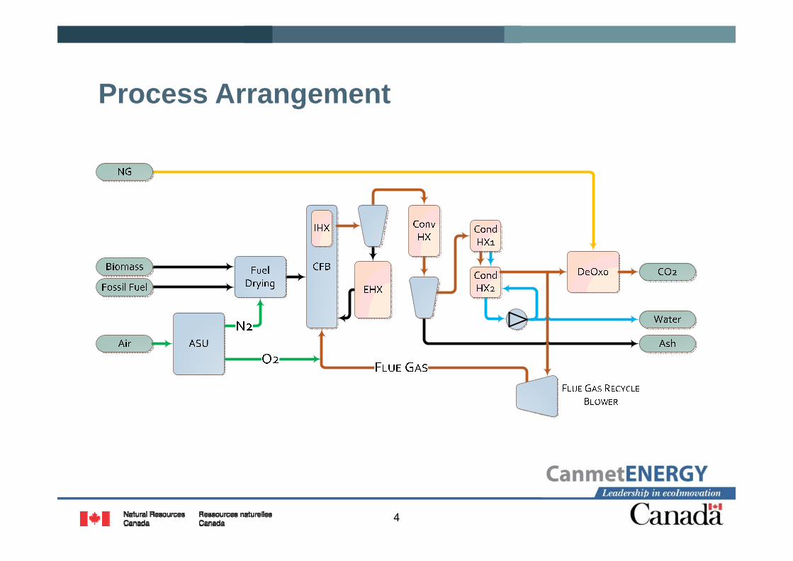
Process Arrangement

5
Oxy-fuel Process Simulation – PFBC
Process Simulations have been completed to: Generate hot composite curves (enthalpy vs temperature) of the proposed configuration to
select suitable operating conditions to match heating requirements of industrial heat and power applications
Establish how much useful heat is available for process heating for various pressures, fuels, and fluidizing gas oxygen concentrations We have assumed that heat must be above 130°C to be useful for the purpose of this study – this is
of course application specific Determine boiler efficiency (HHV): Heat input of all fuels / steam enthalpy Determine power requirements for ASU, recycle flue gas blower, condensate pump, and
CO2 compressor
Range of conditions studied Pressure 1 bar(g) to 40 bar(g) with base case of 15 bar(g) Airex torrefied wood (TW), Boundary Dam lignite, Highvale sub-bituminous coal Blends of torrefied wood and lignite with 25 wt%, 50 wt% and 75 wt% torrefied wood Oxygen concentration in fluidizing gas for riser of 21 vol%, 30 vol%, 40 vol%, and 50 vol%
with base case of 40 vol% Heating input of solid fuels (wood + coal) maintained constant at 100 MW for all cases
6
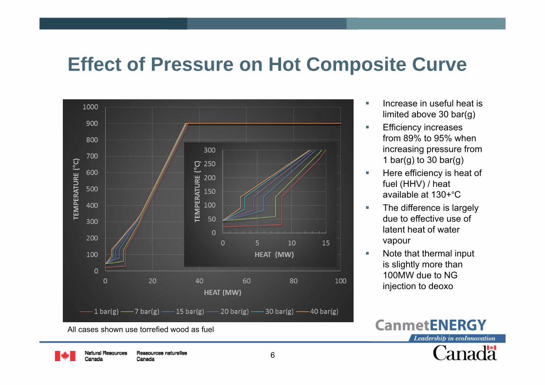
Effect of Pressure on Hot Composite Curve
Increase in useful heat is limited above 30 bar(g)
Efficiency increases from 89% to 95% when increasing pressure from 1 bar(g) to 30 bar(g)
Here efficiency is heat of fuel (HHV) / heat available at 130+°C
The difference is largely due to effective use of latent heat of water vapour
Note that thermal input is slightly more than 100MW due to NG injection to deoxo
All cases shown use torrefied wood as fuel

7
Preliminary Parasitic Power Losses vs Pressure
Study focussed on parasitic power losses that will change substantially due to combustor pressure
Air separation unit including O2 compressor, flue gas recycle blower, condensate recirculation pump for flue gas condenser, CO2compressor
As pressure increases the parasitic losses are reduced until ~10 bar(g)
Many studies show that parasitic load is at a minimum at about 5 to 10 bar(g); we need to understand why this minimum does not appear here
Fluid temperature in advanced ‘indirect’ power cycles
All cases shown use torrefied wood as fuel; 40 vol.% O2

8
Effect of Fuel on Hot Composite Curves
The difference in temperature-heat curves amongst the fuels and the fuel blends is minimal
This is in part due to the fuel drying step in which waste heat from the ASU is used
Changing fuel blends depending on market conditions and fuel availability may have a minimal effect on plant operation
HHV (MJ/kg): TW 21.0 Highvale 21.3 Boundary Dam 24.2
15 bar(g) with 40 vol.% O2 for all cases shown

9
Effect of Oxygen Concentration on Availability of High Temperature Heat
Heat available at high temperature is strongly dependent on oxygen concentration in the fluidizing gas
Higher oxygen concentration will permit Lower heat exchanger
surface area reducing capital cost
Allow higher power cycle temperatures increasing efficiency
Increase useful heat available overall
Agglomeration is the critical risk factor with high pO2; careful combustor design must mitigate this risk
Fluid temperature in advanced ‘indirect’ power cycles
All cases shown use torrefied wood as fuel; 15 bar(g)

10
Approach To Using Biomass in Oxy-PFBC
No limestone or dolomite addition to combustor Eliminates sorbent feed system Reduces quantity of ash Increases heat available at high temperature Reduce risk of agglomeration with Ca, Mg, Na, K
binary eutectics
High pressure sulphur and NOX removal 2SO2 + 2H2O + O2 → 2H2SO4
Catalyzed by NOX with oxidation of NO being the rate determining step
Reaction rate increases with pressure to the third power
End products are sulphuric and nitric acid 100% SO2 and 90 – 99% NOX removal reported
by Air Products
2NO2+H2O → HNO2+HNO3
SO2(l)+HNO3 → NOHSO4
NOHSO4+HNO2 → H2SO4+NO2+NO
SO2(l)+2HNO2 → H2SO4+2NO
2NO+O2 → 2NO2
Zheng, 2011
Chart above shows sulphur removal at elevated pressure via reactions below
11
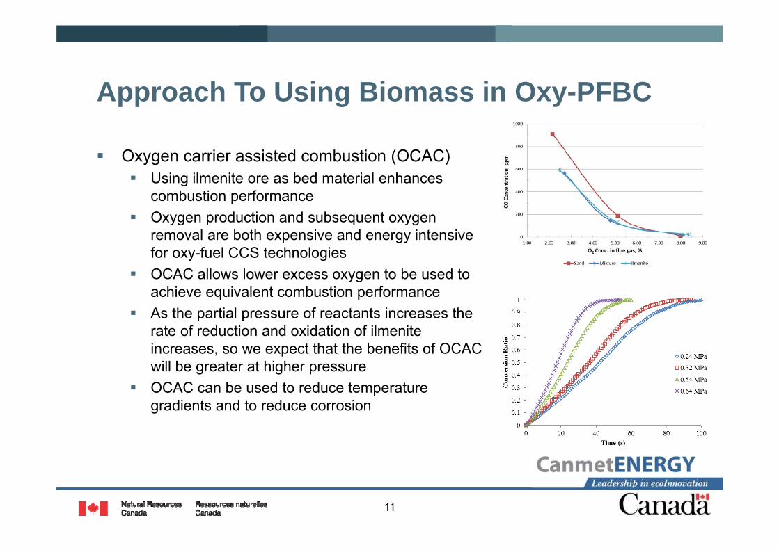
Approach To Using Biomass in Oxy-PFBC
Oxygen carrier assisted combustion (OCAC) Using ilmenite ore as bed material enhances
combustion performance Oxygen production and subsequent oxygen
removal are both expensive and energy intensive for oxy-fuel CCS technologies
OCAC allows lower excess oxygen to be used to achieve equivalent combustion performance
As the partial pressure of reactants increases the rate of reduction and oxidation of ilmenite increases, so we expect that the benefits of OCAC will be greater at higher pressure
OCAC can be used to reduce temperature gradients and to reduce corrosion

12
Approach To Using Biomass in Oxy-PFBC Given that it is relatively difficult to access, maintain,
and inspect heat exchange equipment in pressurized fluidized beds it is imperative that potassium related corrosion is minimized
Ilmenite has been shown to capture potassium at Chalmers Thunman 2013, Corcoran 2014 Formation of KTi8O16 in the ilmenite particle core
Up to about 2 to 3 wt% of K in the ilmenite Should reduce agglomeration and corrosion risk
We are now initiating bench and pilot scale studies to Determine rate of formation of KTi8O16
Determine carrying capacity of potassium in ilmenite Determine concentration of K species in the flue gas Adjust combustor design to improve K capture
Corcoran et al, 2014
Thunman, H., Lind, F., Breitholtz, C., Berguerand, N., Seemann, M. (2013). ‘Using and oxygen-carrier as bed material for combustion of biomass in a 12 MWth circulating fluidized bed boiler’, Fuel 113, pp 300 – 309.Corcoran, A., Marinkovic, J., Lind, F., Thunman, H., Knutsson, P., Seeman, M. (2014). ‘Ash properties of ilmenite used as bed material for combustion of biomass in a circulating fluidized bed boiler’, Energy & Fuels 28, pp 7676-7669.

13
50 kWthOxy-FBC
Gas Analysis
Stack
WINDBOX
RECYCLE BLOWER
BAGHOUSE
CYCLONE
CONDENSER
Condensate Sampling
PRIMARY FLOW
SolidsSampling
AIRPrimary O2 / Mixed Gases
PRESSURIZED HOPPER DRY FEED SYSTEM
CO2
CO2
Contains an internal sintered
filter for fines collection
CO2
ELECTRIC HEATERS
Gas Analysis
SolidsSampling
COMBUSTOR

14
Test Matrix for OCAC at 50 kWth
Test Firing Mode Temp. °C Fuel Bed Material Ca/S O2 % in Flue Gas
# 1 Oxy-fuel 850Highvale sub-bit Sand
0 7-9, 4-6, 2-3
# 2 Oxy-fuel 850Highvale sub-bit Ilmenite
0 7-9, 4-6, 2-3, 4-6
# 3 Oxy-fuel 850Highvale sub-bit Sand-ilmenite
(50:50)
0 7-9, 4-6, 2-3
# 4 Oxy-fuel 800, 850, 900 Poplar River lignite
Sand-ilmenite (50:50)
2 4-6, 2-3
# 5 Oxy-fuel 800, 850, 900 Poplar River lignite Ilmenite
2 4-6, 2-3
# 6 Oxy-fuel 800, 850, 900 Poplar River lignite Sand
2 4-6, 2-3
# 7 Oxy-fuel 800, 850, 900 Poplar River lignite
Fresh sand-ilmenite (50:50)
2 4-6, 2-3
Bubbling bed combustion
Hughes, R.W., Lu, D.Y., Symonds, R.T. (2017). ‘Improvement of oxy-FBC using oxygen carriers: concept and combustion performance’, Energy & Fuels 31(9), pp 10101-10115.

15
Sulphur Concentration in Flue Gas
Oxygen carrier greatly reduced SO2 concentration in flue gas
Enhanced performance of limestone sulphur sorbent CaCO3 + SO2 + 1/2O2 →
CaSO4 + CO2
Oxygen carriers have been used to burn sulphur and sulphur bearing fuels in CLC
Possible reduction to acid dew point allowing increased cycle efficiency
Potential approach to reducing SO2 emissions in air-fired CFBC

16
Carbon Monoxide
CO concentration is lower in the bed section with oxygen carrier
Combustion of CO in the riser is important both with and without oxygen carrier
Possible improvement to air blown CFBC performance Elevated NOx will need to be managed

17
Nitrogen Species Concentration
Increase in NO concentration is evidence that reducing zones are less prevalent
NO can be removed in CO2 purification system and aids in SO2 removal
Highvale
Poplar River

18
Oxy-PFBC 1 MWth Pilot Plant Process Diagram
Diagram depicts Oxy‐PFBC facility at CanmetENERGY

19
Solid Fuel & Sorbent Supply
3. The mixture of fuel and sorbent are brought to combustion pressure using a lock hopper. The fuel then falls into the injection vessel that contains an auger for metering the fuel and sorbent mixture into a conveying line for injection into the PFBC.
2. The fuel and sorbent are conveyed to hoppers equipped with gravimetric feeders that meter the fuel and sorbent into a powder blender.
1. Pulverized solid fuel and sulphur sorbent are delivered to the facility in bulk bags. The bags are placed in bulk bag unloaders.

20
Bulk Gas Supply
1. Oxygen is supplied from two cryogenic tanks. The oxygen is injected into the recycled flue gas through a diffuser.
3. Carbon dioxide is supplied from two cryogenic tanks. The CO2 is used for fuel & sorbent conveying and purges.
4. Natural gas is compressed for use in the high pressure start-up burner and for use in the Linde DeOxoreactor.
2. Twin rotary compressors provide air for the high pressure start-up burner and the PFBC in-bed heat exchanger.

21
Oxy-PFBC, Filter & RFG
1. The PFBC operates at up to 16 bar as a bubbling bed with an in-bed heat exchanger (IHX) allowing cooling via supercritical CO2, thermal fluid and air. Further heat is extracted in two convective heat exchangers via thermal fluid (CHX1 & 2).
3. The filter removes fly ash slightly above the acid dew point temperature.
4. Particulate free flue gas is recycled to moderate the combustor temperature.
2. Bed ash and fly ash are depressuredthrough lock hoppers and pneumatically conveyed to storage.

22
CO2 Purification
1. Flue gas is cooled in the direct contact cooler (packed column) by recycled process condensate. Heat is extracted from the process condensate to recover the heat of condensation (T>110°C). A condensate filter removes any remaining fine solids.
2. NOX and SOX are removed to meet CO2 pipeline specification in the LICONOX column by recycled wash water containing NaOH.
3. Natural gas is injected into the flue gas. O2 is oxidized via catalytic combustion to meet CO2 pipeline specification. Heat is recovered at T > 400°C.
4. Purified CO2is produced at up to 16 bar.