cmu series heating mantle instruction book · instruction book in order to preserve the protection...
TRANSCRIPT

Page 1 of 32 M7153 Issue 7.1
CMU SERIES HEATING MANTLE INSTRUCTION BOOK

Page 2 of 32 M7153 Issue 7.1
Please take your time to read this Instruction book in order to understand the safe and correct use of your new Thermo Fisher Scientific product. To prevent injury or equipment damage it is the manufacturer’s recommendation that the Responsible Body for use of this equipment reads this Instruction book and ensures the user(s) are suitably trained in its operation before use. Contents. Section 1. Introduction Page 3 Section 2. Symbols and using this instructions book. Page 4 Section 3. Safety Information. Page 5 Section 4. Unpack and Contents. Page 7 Section 5. Installation. Page 10 Section 6. Environmental Protection. Page 11 Section 7. Product Operation. Page 12 Section 8. Technical Specifications. Page 17 Section 9. Maintenance Page 22 Section 10. Parts and Accessories Page 27 Section 11. Customer Support Page 29 Section 12. Notes Page 31 Section 13. EC Declaration of Conformity. Page 32 Appendix ‘A’ Decontamination Certificate Page 30
© The copyright of this Instruction book is the property of Thermo Fisher Scientific. This Instruction book is supplied by Thermo Fisher Scientific on the express understanding that it is to be used solely for the purpose for which it is supplied. It may not be copied, used or disclosed to others in whole or part for any purpose except as authorised in writing by Thermo Fisher Scientific. Thermo Fisher Scientific reserve the right to alter, change or modify this document with out prior notification. In the interest of continued development Thermo Fisher Scientific reserve the right to alter or modify the design and /or assembly process of their products without prior notification.
This product is manufactured in Great Britian by Electrothermal Engineering Limited. Part of the Thermo Fisher Scientific Group of companies. Registered address. Thermo Fisher Scientific. Electrothermal House. Unit12A, Purdeys Way. Purdeys Industrial Estate. Rochford, Essex. SS4 1ND Great Britain. Tel +44(0)1702 303350 Fax+44(0)1702 468731 [email protected] www.thermo.com www.electrothermal.co.uk www.stemcorp.co.uk

Page 3 of 32 M7153 Issue 7.1
1. INTRODUCTION.
1.1. The Thermo Fisher Scientific series of heating mantles has been specifically designed to provide a comprehensive answer to heating fluids in round bottomed flasks in the modern laboratory. It combines the traditional Electrothermal heating element with many new features thus providing the user with several options to meet different applications.
1.2. For controlled mantles, heating control is provided by a built-in solid state simmerstat or an
Egostat energy regulator (Size 4 mantles only). For uncontrolled mantles, a range of external controllers are available.
1.3. All CMU products are housed in aluminium cases with stove paint finish to give good
chemical resistance.
1.4. These products are provided with ventilation slots in the base and around the rim to allow convection cooling and subsequent low case operating temperature. On all CMU sizes up to five litres a single support rod positioning clamp is provided at the side of the unit. On the 10, 12, 20 and 22 litre models there are three rod support positions. All mantles have a built in Earth Screen denoted with the suffix ‘E’ or heater element with earth Line, suffix ‘L’.

Page 4 of 32 M7153 Issue 7.1
2. SYMBOLS AND USING THIS INSTRUCTION BOOK
2.1. Throughout this Instruction book the following symbols are shown to identify conditions which pose a hazard to the user, or to identify actions that should be observed. These symbols are also shown on the product, or its packaging. When a symbol is shown next to a paragraph or statement it is recommended the user takes particular note of that instruction in order to prevent damage to the equipment or to prevent injury to one’s self or other people.
The Responsible Body and the Operator should read and be familiar with this Instruction book in order to preserve the protection afforded by the equipment.
2.2. Symbols Defined.
Caution, risk of danger. See note or adjacent symbol.
This symbol adjacent to an indication lamp means the heater power Off / On when the lamp non-illuminated / illuminated.
Protective conductor terminal to be earthed. (Do not loosen or disconnect).
This symbol adjacent to an indication lamp means mains power Off / On when lamp non-illuminated / illuminated.
Caution / risk of electric shock.
Material irritant to skin. When handling wear face mask to BS/EN 149 and protective gloves
Recyclable Packing Material.
Do not dispose of product in normal domestic waste.
Caution. Hot surface.
Refer to Instructions book
Bio Chemical Hazard. Caution required. Will require decontamination.

Page 5 of 32 M7153 Issue 7.1
3. SAFETY INFORMATION.
3.1. This product has been designed for safe operation when used as detailed in accordance with the manufacturer’s instructions.
NOTE: Failure to use this equipment in accordance with this instruction book may compromise your basic safety protection afforded by the equipment and may invalidate the warranty / guarantee. The warranty / guarantee does not cover damaged caused by faulty installation or misuse of the equipment.
3.2. Prevention of Fire and Electric shock.
To prevent a risk of fire or electric shock, DO NOT open your product case without authorisation. Only qualified Service personnel should attempt to repair this product.
Replace fuses only with the type as listed in section, Parts and Accessories and Technical Specifications. (See fuse type and rating).
Ensure the Mains Power Supply conforms to rating found on the data plate located on the product case.
Never Operate this equipment with out connection to earth / ground. Ensure the mains supply voltage is correctly earthed / grounded in accordance with current area legislation.
Do not install or remove any heating mantle from the mains input lead or external controller while power is applied.
3.3. General Safe Operating Practice.
Always follow good laboratory practice when using this equipment. Give due recognition to your company’s safety and legislative health & safety procedures and all associated legislation applicable to your areas of operation. Check laboratory procedures for substances being heated and ensure all hazards (e.g. explosion, implosion or the release of toxic or flammable gases) that might arise have been suitably addressed before proceeding. When heating certain substances the liberation of hazardous gases may require the use of a fume cupboard or other means of extraction.
Avoid Spillages: Always fill the glassware / vessel away from the heating mantle. Only introduce a charged, clean, dry flask into the heating mantle.
Ensure equipment is used on a clean, dry, non-combustible, solid work surface with at least 300mm suitable clearance all around from other equipment.
Do not position the product so that it is difficult to disconnect from the mains supply.
Do not touch the heating element or any glass vessel whilst in use.
Do not lean or stretch over equipment, glassware and fixings when in use.
Do not immerse unit in water or fluids.
Do not spill substances onto the mantle. If spillage does occur, disconnect unit from mains supply and follow instructions as detailed in Maintenance. (Section 9).

Page 6 of 32 M7153 Issue 7.1
Do not cover the mantle whilst in use. Do not block or obstruct ventilation slots / airways.
Only use an Earth screened mantle with electrically conductive vessels. Size 4 (10, 12, 20 and 22 litre) mantles should only be used with glass vessels.
Do not leave equipment switched on without a charged flask.
Do not thermally insulate the exposed upper section of the vessel, as the insulation used may obstruct the convection cooling airways around the rim of the cartridge enclosure and cause the mantle to overheat.
It is not recommended to leave any heating apparatus unattended during operation.
Only use Original Equipment manufactures spares and accessories. Ref Section 10.
Stirring versions of this equipment generate magnet fields. Keep all metal objects and magnetic data devices (e.g. credit cards) away from the stirrer unit.
The equipment is not spark, flame or explosion proof and has not been designed for use in hazardous areas in terms of BSEN 60079-14:1997. Keep flammable, low flash point substances away from the apparatus.
Do not operate or handle any part of the product with wet hands.
Mantles which do not have a built in controller should only be used with an external means of control. (Never connect directly to the mains supply).
Keep the Mains cord and moulded IEC plug and lead set away from the heating surface.
ATTENTION:- With high energy input and certain configurations of glassware in CMU products, where the heating contact of glassware is relatively small, localised heating and subsequent ‘bumping’ of the fluid being heated may occur. Application advice should be sought from the manufacturer.
NOTE: if this product is not used in accordance with the Manufacturers Instructions then the basic safety protection afforded by the equipment may not be preserved and the guarantee invalidated.

Page 7 of 32 M7153 Issue 7.1
4. UNPACKING AND CONTENTS.
4.1. Product Identification:
The following tables identify the different sizes and groups within the CMU family.
Case Size Uncontrolled. C (Controlled). (230V) (115V) (230V) (115V)
1 CMU0050/E CMU0050/EX1 CMU0050/CE CMU0050/CEX1 CMU0100/E CMU0100/EX1 CMU0100/CE CMU0100/CEX1 CMU0250/E CMU0250/EX1 CMU0250/CE CMU0250/CEX1
2 CMU0500/E CMU0500/EX1 CMU0500/CE* CMU0500/CEX1* CMU1000/E CMU1000/EX1 CMU1000/CE* CMU1000/CEX1*
3 CMU2000/E CMU2000/EX1 CMU2000/CE* CMU2000/CEX1* CMU3000/E CMU3000/EX1 CMU3000/CE* CMU3000/CEX1* CMU5000/E CMU5000/EX1 CMU5000/CE* CMU5000/CEX1*
Case Size Uncontrolled Bottom Drain Off C (Controlled) Bottom Drained Off (230V) (115V) (230V) (115V)
4 CMUV10/L CMUV10/LX1 CMUV10/CL CMUV10/CLX1 CMUV12/L CMUV12/LX1 CMUV12/CL CMUV12/CLX1 CMUV20/L CMUV20/LX1 CMUV20/CL CMUV20/CLX1 CMUV22/L CMUV22/LX1 CMUV22/CL CMUV22/CLX1
Case Size Uncontrolled 3 in 1 shaped Earth Screen
C (Controlled) 3 in 1 shaped Earth Screen.
(230V) (115V) (230V) (115V) 2 CMUT1000/E* CMUT1000/EX1* CMUT1000/CE* CMUT1000/CEX1*
Case Size C (Controlled) with Stir facility (230V) (115V)
2 CMUA0050/CE CMUA0050/CEX1 CMUA0100/CE CMUA0100/CEX1 CMUA0250/CE CMUA0250/CEX1
2 CMUA0500/CE* CMUA0500/CEX1* CMUA1000/CE* CMUA1000/CEX1*
3 CMUA2000/CE* CMUA2000/CEX1* CMUA3000/CE* CMUA3000/CEX1* CMUA5000/CE* CMUA5000/CEX1*

Page 8 of 32 M7153 Issue 7.1
A Catalogue number allocated to each type of mantle is descriptive. The method of coding is detailed below. First, second and third Characters CMU Series
Next Character ‘A’ unit with stir facility. ‘V’ Bottom opening for drain off.
Next four Characters Flask size in ml. 0050, 0100, 0500, 1000, 2000, 3000, 5000.
Next Character ‘C’ Controlled.
Next Character ‘E’ Earthed screen.
Last Characters No Characters = 230V, X1 = 115V,
Notes: On Size 4 cases ‘L’ designates the presence of an earth line adjacent to the element instead of an earth screen. Where controlled, the larger case size 4 mantles use ego stat energy regulators. All other smaller controlled mantles use a solid state simmerstat controller. * Denotes a switch fitted for two heater circuits. For uncontrolled mantles size 1, 2, & 3, the MC5 or MC5x1 controller may be used. The MC5 Controller uses solid state simmerstat controlling. For uncontrolled mantles size 4, the MC242 or MC242x1 may be used. The MC242 Controller uses an egostat energy regulator. For the three circuit models (i.e. three IEC socket inputs) these can be supplied by three MC242 controllers.
The following mantles in the table below contain three separate circuits with three IEC socket inlets.
Size 4 case CMUV10/L CMUV10/LX1 CMUV12/L CMUV12/LX1 CMUV20/L CMUV20/LX1 CMUV22/L CMUV22/LX1
The following mantles in the table below contain three separate circuits with three IEC inlets and three onboard controllers.
Size 4 case CMUV10/CL CMUV10/CLX1 CMUV12/CL CMUV12/CLX1 CMUV20/CL CMUV20/CLX1 CMUV22/CL CMUV22/CLX1

Page 9 of 32 M7153 Issue 7.1
Please check the contents of your carton against the relevant product diagram.
Applicable to all CMU product.
For future reference please record your products Serial and Model Numbers.
Serial Number Unit Model/Cat Number
Item No
Description Qty
1 Instruction Book 1
2 Mains cord and Moulded Plug and Lead set
1 or (3 - see variant)
3 CMU Product – (May vary from illustration).
1
4 Stir bar (Only on CMUA variant).
1 Pkt

Page 10 of 32 M7153 Issue 7.1
5. INSTALLATION.
5.1. Electrical safety and installation.
5.1.1. This equipment is designed to be used safely under the following conditions:-
• Indoor use.
• Altitude up to 2000 meters.
• Temperatures between 5°C and 40°C.
• Maximum relative humidity 80% for temperatures up to 31°C decreasing linearly to 50% relative humidity at 40°C.
• Mains supply voltage fluctuations up to ± 10% of the nominal voltage.
• Transient overvoltages typically present on the mains supply.
• Applicable rated pollution degree 2.
5.1.2. This equipment must be earthed / grounded to a fixed earth / grounded mains socket outlet. The mains supply is to earthed / grounded in accordance with current legislation.
5.1.3. Ensure only the correct rated mains input fuses are fitted. (Where applicable ensure
the correct Mains cord and moulded IEC plug and lead set fuse is fitted). See Technical Information Section 8 of this Instruction book.
5.1.4. Check the voltage on the product data label on this product unit and those of any
accompanying electrical accessory. Ensure the rating conforms to your local supply.
5.1.5. This product should be connected to a mains supply source which incorporates an RCD or GFCI device that has a tripping current of 30mA or less. The RCD or GFCI residual Current Device cuts off power to the equipment immediately it detects a current leakage fault. For example, cutting off the power when there is an accidental liquid spillage in a mantle protected with an earth (ground) screen.
5.1.6. Do not install this product or accessories on a surface which may become flooded.
5.1.7. The unit is supplied with a Mains cord and moulded IEC plug and lead set wired as
follows.
Green / Yellow or
Green
=
Earth / Ground
Blue or White = Neutral
Brown or Black = Live / line hot.
Observation: the surface of the heating element of a mantle cartridge will upon receipt look slightly discoloured. This discolouration is normal and occurs at the factory during test when the mantle is first heated up.
Note: Thermo Fisher Scientific controllers, series MC242 / MC5 are used on uncontrolled mantles and can also be used for external control when the mantle is used in a fume cupboard.
5.1.8. Heating Mantle product should only be directly connected to the mains power supply outlet using the moulded lead sets provided with the equipment. Extension cords should not be used unless authorised by a competent Electrician, after review of CMU equipments electrical power ratings.

Page 11 of 32 M7153 Issue 7.1
6. ENVIRONMENTAL PROTECTION.
6.1. Thermo Fisher Scientific has given due consideration to environmental issues within the design and manufacturing process without compromising end product performance and value.
6.2. Packaging materials have been selected such that they may be sorted for recycling.
6.3. At the end of your product and accessories life, it must not be discarded as domestic waste. Ref: EU Directive 2002/96/EC on Waste Electrical and Electronic Equipment Directive (WEEE). Please contact your distributor / supplier for further information. For end users outside of the EU consult applicable regulations.
6.4. This product should only be dismantled for recycling by an authorised recycling company.
This product and accessories must be accompanied by a completed Decontamination Certificate prior to any disposal. Copies of the Certificate are available from your distributor of Thermo Fisher Scientific products, or you may copy and enlarge from ‘Appendix A’ of the instruction book.
Thermo Fisher Scientific is registered as Electrothermal Engineering Limited with the Environment Agency as a producer of WEEE through an authorised compliance scheme.

Page 12 of 32 M7153 Issue 7.1
7. PRODUCT OPERATION.
7.1. CMU Mantle without Controller.
Note: This product will require an MC Controller to operate it.
7.1.1. With the mains electricity supply turned off, connect the IEC plug attached to the
lead coming out of the MC Controller to the IEC socket of the mantle as illustrated.
(Illustration of controller may be different depending on your model).
Item Description. 1
Heating Element.
2 Hot surface warning
3 Refer to Instruction Book Label.
4 Data Plate (Refer to for correct voltage).
5 Protective Conductor Terminal (Do not Loosen or disconnect).
6 Mains Input IEC socket (Contains protective fuses).
7 Support rod bracket (Note: For 10 to 22 litre size 4 cases, 3 clamps are fitted).
8 Clear Neon. (will illuminate / pulsate when the power is supplied to heater.

Page 13 of 32 M7153 Issue 7.1
7.1.2. Plug the mains lead supplied with the MC controller into the IEC socket of the controller.
7.1.3. Place a charged, clean, dry glass vessel of the size indicated on the mantle data
plate label. Wherever possible the glass vessel should be supported within the mantle by means of the support rod and clamp.
7.1.4. Switch on the mains electrical supply. Adjust the controller regulator knob to the
required setting. (Refer to Controller ‘Operating and Safety Instructions’ document for further information on the controller).
7.1.5. When the process is complete switch the controller regulator knob to the off
position. Disconnect the mains electricity supply.
7.1.6. Remove charged vessel. Handle hot charged vessel with care.
7.2. CMU Mantle with inbuilt Controller.
7.2.1. With the mains electricity supply switched off, connect the Mains cord and moulded IEC plug and lead set to the mains IEC socket.
7.2.2. Place a charged, clean, dry glass vessel of the size indicated on the mantle data
plate label. Wherever possible the glass vessel should be supported within the mantle by means of the support rod and clamp.
7.2.3. Switch on the mains electrical supply. Adjust the controller regulator knob to the
required setting. Setting 1 is low heat up to setting 10 maximum heat.
NOTE: The ‘mains power on’ indication neon will illuminate. The ‘amber heating on’ neon will illuminate / pulsate when the heaters are in operation.
7.2.4. When the process is complete switch the regulator knob to the off position.
Disconnect the mains electricity supply.
7.2.5. Remove charged vessel. Handle hot charged vessel with care.
Item Description. 1
Heating Element.
2 Hot surface warning
3 Refer to Instruction Book Label.
4 Data Plate (Refer to for correct voltage).
5 Protective Conductor Terminal (Do not Loosen or disconnect).
6 Mains Input IEC socket (Contains protective fuses).
7 Support rod bracket (Note: For 10 to 22 litre size 4 cases, 3 clamps are fitted).
8 Heating control knob.
9 Mains power on indicator.
10 Heating Element on indicator.

Page 14 of 32 M7153 Issue 7.1
7.2.6. CMU Size 4 with 3 Controller Inputs.
7.2.7. Take 3 x MC controllers. With the mains electricity turned off connect the IEC output
plug from each controller into to an input socket on the Mantle. (DO NOT USE AN EXTENSION BLOCK RUNNING FROM THE MAINS ON A SINGLE CABLE).
7.2.8. Plug each mains lead supplied with the MC controller into the IEC socket of the
controller.
7.2.9. Place a charged, clean, dry glass vessel of the size indicated on the mantle data plate label. Wherever possible the glass vessel should be supported within the mantle by means of the support rod and clamp.
7.2.10. Switch on the mains electrical supply to each controller. Adjust each controllers
regulator knob to the required setting. (Refer to Controller ‘Operating and Safety Instructions’ document for further information on the controller).
7.2.11. When the process is complete switch the controller regulator knob on each
controller to the off position. Disconnect all mains electricity supply.
7.2.12. Remove charged vessel. Handle hot charged vessel with care.
Item Description. 1 Refer to Instruction Book Label.
2 Heating Element.
3 Support rod bracket (Note: For 10 to 22 litre size 4 cases, 3 clamps are fitted).
4 Data Plate (Refer to for correct voltage).
5 Mains Input IEC socket (Contains protective fuses).
6 Protective Conductor Terminal (Do not Loosen or disconnect).

Page 15 of 32 M7153 Issue 7.1
Glassware should always be supported to maintain the glassware in a vertical position. It is recommended that for all CMU products that the round bottomed glassware should only be filled to the equator. This ensures maximum heating efficiency and, for larger mantle size 4, prevents excessive loads being applied to into the mantle where separate glassware gantry supports are not being used. For mantles without an earth screen, care needs to be taken when introducing loaded round bottomed 10L (12L) & 20 L (22L) glassware into the electromantle: glassware must be introduce vertically and not allowed to drag down the side of the knitted carrier / element. For installations where additional glassware may be stacked on top of round bottomed flask, or where bottom drain off feature is being used, then we would always recommend that the glassware is separately supported on gantry arrangement and the heating mantle be jacked up underneath the glassware, such that the full load of the glassware is not taken by the mantle.

Page 16 of 32 M7153 Issue 7.1
7.3. CMU with Stir control.
7.3.1. With the mains supply switched off. Connect the mains lead and moulded IEC plug and lead set to the mains IEC socket.
7.3.2. Place a charged, clean, dry glass vessel of the size indicated on the mantle data
plate. Wherever possible the glass vessel should be supported within the mantle by means of the support rod and clamp. Place Stir bar in vessel contents.
7.3.3. Switch on the mains electricity supply. Adjust the heater control regulator knob to
the required setting.
NOTE: The mains power on indication neon will illuminate. The amber heating on neon will illuminated when the heaters are in operation.
7.3.4. On the EMA there are three stirring functions available. a) Bi-directional with auto capture and auto reverse period of approximately 20 / 30
seconds.
b) Uni-directional up to 500RPM approximately.
c) Manual capture / reset.
7.3.5. Carefully place the stirrer bar provided into the vessel and turn the rotational speed control to its minimum position.
7.3.6. Select the centre position of the position selector switch.
7.3.7. Switch the stirrer unit on. The green LED will now illuminate.
7.3.8. Adjust the rotational speed by means of the speed control knob. Should the stirring
action be lost by over rotation, then reduce the stir speed slightly and recapture the stir bar by depressing the selector switch in the lowest position. Once the correct stirring speed has been obtained then, if desired, the selector switch may be set in the uppermost position to obtain the auto reverse function.
7.3.9. When the process is complete switch the stir speed and regulator knobs to there off
positions. Disconnect the mains electricity supply.
7.3.10. Remove charged vessel. Handle hot charged vessel with care.
Item Description. 1
Heating Element.
2 Hot surface warning
3 Refer to Instruction Book Label.
4 Data Plate (Refer to for correct voltage).
5 Protective Conductor Terminal (Do not Loosen or disconnect).
6 Mains Input IEC socket (Contains protective fuses).
7 Support rod bracket (Note: For 10 to 22 litre size 4 cases, 3 clamps are fitted).
8 Temperature control knob.
9 Power present indicator.
10 Heating on indicator 11 By directional stirring with Auto
capture switch. 12 Stir facility ‘Op’ indicating LED 13 Stir speed controller.

Page 17 of 32 M7153 Issue 7.1
8. TECHNICAL SPECIFICATIONS.
8.1. General specification for the CMU Range.
X1 Product – mains supply voltage (115V ~ AC)
115Volts ~ AC ± 10% at 50/60 Hz.
Mains input supply voltage (230V ~ AC).
230Volts ~ AC ± 10% at 50/60 Hz.
Fuse Type. 20mm x 5mm Glass Quickblow (2 per unit) See rating table below.
Heating Element Construction. Thermal insulated element wire stitched into a cartridge construction.
Maximum Element Temperature. 450°C. Nominal Max.
CMU Case Construction. Aluminium.
Thermal Insulation. Rockwool mineral insulation. Size 1, 2, and3. Ceramic Size 4.
Mains cord and moulded IEC plug and lead set cable (UK) 13A BS1362 AZ9165
3 core earthed / ground. 2 meters long Moulded IEC plug and Lead set – supply cord H05 V V-F- Replace only with equivalent cable.
Mains cord and moulded IEC plug and lead set cable (Europe) AZ6747
3 core earthed / ground. 2 meters long Moulded IEC plug and Lead set – supply cord H05 V V-F- Replace only with equivalent cable.
Mains cord and moulded IEC plug and lead set cable (USA) AZ6746
3 core earthed / ground. 2 meters long Moulded IEC plug and Lead set – supply cord SJT VW 1- 105° Replace only with equivalent cable.
Mains cord and moulded IEC plug and lead set cable (Switzerland) AZ6175
3 core earthed / ground. 2 meters long Moulded IEC plug and Lead set – supply cord W W 05 VAS-F- Replace only with equivalent cable.
Mains cord and moulded IEC plug and lead set cable (Australia) M7079
3 core earthed / ground. 2 meters long Moulded IEC plug and Lead set – supply cord H05 V V-F Replace only with equivalent cable.

Page 18 of 32 M7153 Issue 7.1
8.2. Power Consumption and fuse ratings.
Size Type Total Heating Power (Watts)
Fuse Rating (Amps)
(230v) (115v) (230v) (115v) 1 CMU0050/E 75 - 500mA - CMU0100/E 100 - 1 - CMU0250/E 200 - 1.25 - CMU0050/EX1 - 75 - 1 CMU0100/EX1 - 100 - 1.25 CMU0250/EX1 - 200 - 2.5 CMU0050/CE 60 - 500mA - CMU0100/CE 60 - 500mA - CMU0250/CE 150 - 1.25 - CMU0050/CEX1 - 75 - 1.25 CMU0100/CEX1 - 75 - 1 CMU0250/CEX1 - 150 - 2.5
2 CMUA0050/CE 60 - 1 - CMUA0100/CE 60 - 1 - CMUA0250/CE 200 - 1.25 - CMUA0050/CEX1 - 76 - 1.25 CMUA0100/CEX1 - 76 - 1.25 CMUA0250/CEX1 - 200 - 2.5 CMU0500/E 280 - 2.5 - CMU1000/E 380 - 2.5 - CMU0500/EX1 - 280 - 3.15 CMU1000/EX1 - 380 - 5 CMU0500/CE 200 - 1.25 - CMU1000/CE 300 - 2.5 - CMU0500/CEX1 - 200 - 1.25 CMU1000/CEX1 - 300 - 2.5 CMUT1000/E 300 - 2.5 - CMUT1000/EX1 - 300 - 3.15 CMUT1000/CE 300 - 2.5 - CMUT1000/CEX1 - 300 - 3.15 CMUA0500/CE 280 - 2.5 - CMUA1000/CE 380 - 2.5 - CMUA0500/CEX1 - 280 - 3.15 CMUA1000/CEX1 - 380 - 5
3 CMU2000/E 500 - 2.5 - CMU3000/E 500 - 2.5 - CMU5000/E 800 - 5 - CMU2000/EX1 - 500 - 5 CMU3000/EX1 - 500 - 5 CMU5000/EX1 - 800 - 10 CMU2000/CE 500 - 2.5 - CMU3000/CE 500 - 2.5 - CMU5000/CE 800 - 6.3 - CMU2000/CEX1 - 500 - 5 CMU3000/CEX1 - 500 - 5 CMU5000/CEX1 - 800 - 10 CMUA2000/CE 500 - 2.5 - CMUA3000/CE 500 - 2.5 - CMUA5000/CE 800 - 6.3 - CMUA2000/CEX1 - 500 - 6.3 CMUA3000/CEX1 - 500 - 6.3 CMUA5000/CEX1 - 800 - 10

Page 19 of 32 M7153 Issue 7.1
Size Type Bottom Element C1
(230V) Middle Element C2
(230V) Top Element C3
(230V) Watts Fuse Watts Fuse Watts Fuse 4 CMUV10/L 500 3.15 500 3.15 1000 6.3 CMUV12/L 500 3.15 500 3.15 1000 6.3 CMUV20/L 1000 6.3 1000 6.3 1000 6.3 CMUV22/L 1000 6.3 1000 6.3 1000 6.3 CMUV10/CL 500 3.15 500 3.15 1000 6.3 CMUV12/CL 500 3.15 500 3.15 1000 6.3 CMUV20/CL 1000 6.3 1000 6.3 1000 6.3 CMUV22/CL 1000 6.3 1000 6.3 1000 6.3 Type Bottom Element C1
(115V) Middle Element C2
(115V) Top Element C3
(115V) Watts Fuse Watts Fuse Watts Fuse CMUV10/LX1 500 6.3 500 6.3 1000 10 CMUV12/LX1 500 6.3 500 6.3 1000 10 CMUV20/LX1 1000 10 1000 10 1000 10 CMUV22/LX1 1000 10 1000 10 1000 10 CMUV10CLX1 500 6.3 500 6.3 1000 10 CMUV12/CLX1 500 6.3 500 6.3 1000 10 CMUV20/CLX1 1000 10 1000 10 1000 10 CMUV22/CLX1 1000 10 1000 10 1000 10
The Ingress Protection Rating all the CMU and CMUV Mantles is Ingress Protection Rating is IPX0.

Page 20 of 32 M7153 Issue 7.1
8.3. Dimensions and Weight (Unpacked).
Case size
Capacity Product (A)mm (B)mm (C)mm (D)mm W
1 1 1 1 2 2
50ml CMU0050/E CMU0050/EX1 CMU0050/CE CMU0050/CEX1 CMUA0050/CE CMUA0050/CEX1
52 31 150 175 0.75Kg
1 1 1 1 2 2
100ml CMU0100/E CMU0100/EX1 CMU0100/CE CMU0100/CEX1 CMUA0100/CE CMUA0100/CEX1
67 39 150 175 0.75Kg
1 1 1 1 2 2
250ml CMU0250/E CMU0250/EX1 CMU0250/CE CMU0250/CEX1 CMUA0250/CE CMUA0250/CEX1
86 48 150 175 0.75Kg
2 2 2 2 2 2
500ml CMU0500/E CMU0500/EX1 CMU0500/CE CMU0500/CEX1 CMUA0500/CE CMUA0500/CEX1
106 61 170 220 1.5Kg
3 3 3 3 3 3 3 3 3 3
1000ml CMU1000/E CMU1000/EX1 CMU1000/CE CMU1000/CEX1 CMUT1000/E CMUT1000/EX1 CMUT1000/CE CMUT1000/CEX1 CMUA1000/CE CMUA1000/CEX1
136 78 170 220 1.5Kg
3 3 3 3 3 3
2000ml CMU2000/E CMU2000/EX1 CMU2000/CE CMU2000/CEX1 CMUA2000/CE CMUA2000/CEX1
168 94 220 320 2.75Kg
3 3 3 3 3 3
3000ml CMU3000/E CMU3000/EX1 CMU3000/CE CMU3000/CEX1 CMUA3000/CE CMUA3000/CEX1
196 106 220 320 2.75Kg
3 3 3 3 3 3
5000ml CMU5000/E CMU5000/EX1 CMU5000/CE CMU5000/CEX1 CMUA5000/CE CMUA5000/CEX1
224 190 220 320 2.75Kg

Page 21 of 32 M7153 Issue 7.1
Size 4 Product (A)mm (B)mm (C)mm (D)mm (E)mm W 10Litre CMUV10/L
CMUV10/LX1 CMUV10/CL CMUV10CLX1
280 147 300 485 70 6.0Kg
12Litre CMUV12/L CMUV12/LX1 CMUV12/CL CMUV12/CLX1
330 175 300 485 70 6.0Kg
20Litre CMUV20/L CMUV20/LX1 CMUV20/CL CMUV20/CLX1
356 185 300 485 70 8.5Kg
22Litre CMUV22/L CMUV22/LX1 CMUV22/CL CMUV22/CLX1
390 211 300 485 70 8.5Kg

Page 22 of 32 M7153 Issue 7.1
9. MAINTENANCE.
9.1. General Information.
Unplug the unit from the mains voltage supply and allow it to cool before undertaking any maintenance tasks.
Maintenance should only be carried out under the direction of the Responsible Body, by a competent electrician. Failure to do so may result in damage to the product and in extreme cases be a danger to the end user. With proper care in operation this equipment has been designed to give many years of reliable service. Contamination or general misuse will reduce the effective life of this product and may cause a hazard. Maintenance for the unit should include:
• Periodic electrical safety testing (an annual test is recommended as the minimum requirement).
• Regular inspection for damage with particular attention to the mains lead and plug set.
• Routine cleaning of the equipment should be undertaken using a clean cloth. DO NOT USE SOLVENTS FOR CLEANING ANY PART OF THIS EQUIPMENT.
9.2. Fuse Replacement.
The mains fuse holder is located at rear your product. Refer to Technical Specification, ‘Fuse Rating’ for correct fuse type and rating. Turn your product off and disconnect it from the mains supply. Open the draw of the IEC mains electrical input socket. Remove fuses and fit replacement fuses of the correct rate and type – See section 8.

Page 23 of 32 M7153 Issue 7.1
9.3. Heater Cartridge Replacement. (SIZE 1, 2, 3).
CMU mantles contain Rochwool mineral insulation. When handling a suitable face mask which bears the CE mark should be used. A face mask to BS/EN 149 is adequate. When handling, wear gloves. Should skin irritation be experienced it can be lessened by rinsing hands under cold running water before washing. For further information refer to guidance note EH46 published by HMSO and technical data sheets available from Rockwool Limited. Pencoed. Bridgend. CF35 6NY. In the event of a heater element becoming damaged or open circuit the follow procedure should be adopted for its replacement.
CONTROLLED AND STIRRER (SIZE 1, 2, 3).
9.3.1. Remove any glassware from the mantle and unplug or disconnect the mantle from the power supply and allow it to cool down.
9.3.2. Turn the CMU mantle upside down onto a clean dry surface.
9.3.3. Remove the cross-head screws from around the base of the mantle and hinge the
base to one side. Note: the stir motor assembly is attached to the base on the stir version. Lift the base clear with the motor assembly remaining attached to the base.
9.3.4. Remove the cross-head screws retaining the rod support clamp to the case and
remove the clamp. Note: Not necessary on 2, 3, and 5 litre mantles.
9.3.5. Remove the M3 nuts retaining the heater cartridge.
9.3.6. Disconnect two sleeved wires from the IEC socket. On 5 litre mantles only disconnect cartridge wires from switch, IEC socket and inline connector.
9.3.7. Separate case from rim and hinge case away to one side.
9.3.8. Disconnect the Earth wire from the cartridge. (DO NOT DISCONNECT ANY
OTHER EARTH WIRE).
9.3.9. Lift and remove original cartridge.
9.3.10. Position replacement cartridge in top rim and fix in position using clips provided, which locate on the fixing studs. REPLACE THE EARTH WIRE.
9.3.11. Reconnect case ensuring correct alignment to studs cartridge and cartridge wires
are nearest to IEC socket.
9.3.12. Reverse procedure 9.3.6 to 9.3.2 to complete.
9.3.13. The responsible body shall check the electrical safety of the product before further use.

Page 24 of 32 M7153 Issue 7.1
UNCONTROLLED. (SIZE 1, 2, 3).
9.3.14. Remove the glassware from the mantle and unplug or disconnect the mantle from the power supply and allow it to cool down.
9.3.15. Turn the CMU mantle upside down onto a clean dry surface.
9.3.16. Remove the cross-head screws from around the base of the mantle and hinge thwe
base to one side.
9.3.17. Remove the M3 nuts retaining the heater cartridge. Disconnect the heater wires from the clear neon.
9.3.18. Lift the heater cartridge clear of the case.
9.3.19. Disconnect the earth wire tag attached to the heater assemble. (DO NOT
DISCONNECT ANY OTHER EARTH WIRE).
9.3.20. Take replacement heater cartridge and connect the earth lead to the heater earth terminal
9.3.21. Insert the heater cartridge into the case and fasten it to the rim using the M3 nut
previously removed.
9.3.22. Connect the heater wires to the Clear neon.
9.3.23. Fasten the base to the case using the screws previously removed.
9.3.24. The responsible body shall check the electrical safety of the product before further use.
9.4. Heater Cartridge Replacement (SIZE4).
CMUV Size 4 mantles are constructed from using a ceramic fibre under a vacuum. When handling, wear gloves. Should skin irritation be experienced it can be lessened by rinsing hands under cold running water before washing.
In the event of a heater element becoming damaged or open circuit the follow procedure should be adopted for its replacement.
9.4.1. Remove any glassware from the mantle and unplug or disconnect the mantle from
the power supply and allow it to cool down. 9.4.2. Turn the CMUV mantle upside down on a clean dry surface.
9.4.3. Remove the 6 cross head screws securing the base into position located around the
side of the case.
9.4.4. Lift the base and spacer tray assembly clear ensuring the earth wire isn’t stretched or damaged.
9.4.5. Remove the nuts retaining the heater cartridge to the top ring.
9.4.6. Disconnect the heater wire tags from the Amber neon’s (Controlled) or Clear neon
(Uncontrolled).

Page 25 of 32 M7153 Issue 7.1
9.4.7. Undo the earth post retention nut attaining to the heater earth wires and remove the heater wire tags. (DO NOT DISCONNECT ANY OTHER EARTH WIRES). Separate the heater mantle assembly from the rim and lift clear.
9.4.8. Position the replacement cartridge in the top ring.
9.4.9. Reconnect the heater earth wires and retain with previously removed M4 lock nut.
9.4.10. Reconnect the new heaters tags onto terminals of the Amber neon’s (Controlled) or
Clear neon’s (Uncontrolled).
9.4.11. Fasten base and spacer tray assembly back into position using the six screws removed previously.
9.4.12. The responsible body shall check the electrical safety of the product before further
use.

Page 26 of 32 M7153 Issue 7.1
9.5. Spillage and Decontamination.
Spillage: In the event of spillage or glassware fracture, do not touch the mantle. Disconnect the product from the mains electrical supply. Allow the product to cool. Wearing suitable hand protection (giving due consideration to substances that were being heated) carefully remove any pieces of broken glassware. If decontamination is necessary, see section below. Otherwise wipe off all excess liquid from the mantle and surrounding area using an absorbent soft cloth. Drain of any residual fluid retained in the mantle. In the case of excessive spillage/ flask fracture, invert the mantle and allow it to drain for minimum of one hour. Then proceed with the following drying out procedure. Place the complete mantle, correct way up, in a heated oven at 50 °C for a minimum period of 40 hours for sizes 1, 2 & 3 i.e. up to 5000 ml, and for 80 hours minimum for size 4, i.e. 10L up to 22L. ! Warning: The equipment cannot be assumed to meet all the safety requirements of EN 61010-2-010: 2003 during the drying out process and until the drying out process is completed. Prior to further use, the mantle must be subjected to electrical safety testing by competent service personnel. If in doubt please consult Customer Support. Refer to section 11.” NB: Replacement heater cartridges are obtainable from your Distributor/Manufacturer.
Before further use, the mantle must be subjected to electrical safety testing by competent service personnel. If in doubt please consult Customer Support. Refer to section 11.
If the equipment has been exposed to contamination, the Responsible Body is responsible for carrying out appropriate decontamination. If hazardous material has been spilt on or inside the equipment, decontamination should only be undertaken under the control of the Responsible Body with due recognition of possible hazards. Before using any cleaning or decontamination method, the Responsible Body should check with the manufacturer the proposed method will not damage the equipment. Prior to further use, the Responsible Body shall check the electrical safety of the unit. Only if all safety requirements are met can the unit be used again. The above procedure is intended as a guide. Should spillage occur with a toxic or hazardous fluid then special precautions may be necessary.
Decontamination Certificate.
Note: In the event of this equipment or any part of the unit becoming damaged, or requiring service, the item(s) should be returned to the manufacturer for repair accompanied by a decontamination certificate. Copies of the Certificate are available from Distributor/Manufacturer. Appendix A of this instructions book may be copied and enlarged.
At the end of life, this product must be accompanied by a Decontamination Certificate. See section 6.3 and 6.4

Page 27 of 32 M7153 Issue 7.1
10. PARTS AND ACCESSORIES.
10.1. Replacement Heater Cartridges. All Thermo Fisher Scientific (Electrothermal) mantles are specified by the letters RE and Flask size. Add X1 suffix when ordering for 115V.
CMU0050/E CMU0050/CE
Order RECMU0050
CMUA0050/CE Order RECMUA0050
CMU0050/EX1 CMU0050/CEX1
Order RECMU0050X1
CMUA0050/CEX1 Order RECMUA0050X1
CMU0100/E CMU0100/CE
Order RECMU0100
CMUA0100/CE Order RECMUA0100
CMU0100/EX1 CMU0100/CEX1
Order RECMU0100X1
CMUA0100/CEX1 Order RECMUA0100X1
CMU0250/E CMU0250/CE
Order RECMU0250
CMUA0250/CE Order RECMUA0250
CMU0250/EX1 CMU0250/CEX1
Order RECMU0250X1
CMUV0250/E Order RECMUV0250
CMUV0250/EX1 Order RECMUV0250X1
CMU0500/E CMU0500/CE
Order RECMU0250
CMUA0500/CE Order RECMUA0500
CMU0500/EX1 CMU0500/CEX1
Order RECMU0250X1
CMUA0500/CEX1 Order RECMUA0500X1
CMU1000/E CMU1000/CE
Order RECMU1000
CMUA1000/CE Order RECMUA1000
CMU1000/EX1 CMU1000/CEX1
Order RECMU1000X1
CMUA1000/CEX1 Order RECMUA1000X1
CMUT1000/E CMUT1000/CE
Order RECMUT1000
CMUT1000/EX1 CMUT1000/CEX1
Order RECMUT1000X1
CMU2000/E CMU2000/CE
Order RECMU2000
CMUA2000/CE Order RECMUA2000
CMU2000/EX1 CMU2000/CEX1
Order RECMU2000X1
CMUA2000/CEX1 Order RECMUA2000X1
CMU3000/E CMU3000/CE
Order RECMU3000
CMUA3000/CE Order RECMUA3000
CMU3000/EX1 CMU3000/CEX1
Order RECMU3000X1
CMUA3000/CEX1 Order RECMUA3000X1
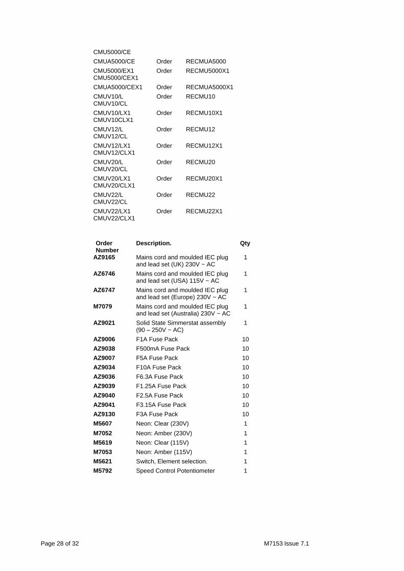
CMU5000/E Order RECMU5000
Page 28 of 32 M7153 Issue 7.1
CMU5000/CE
CMUA5000/CE Order RECMUA5000
CMU5000/EX1 CMU5000/CEX1
Order RECMU5000X1
CMUA5000/CEX1 Order RECMUA5000X1
CMUV10/L CMUV10/CL
Order RECMU10
CMUV10/LX1 CMUV10CLX1
Order RECMU10X1
CMUV12/L CMUV12/CL
Order RECMU12
CMUV12/LX1 CMUV12/CLX1
Order RECMU12X1
CMUV20/L CMUV20/CL
Order RECMU20
CMUV20/LX1 CMUV20/CLX1
Order RECMU20X1
CMUV22/L CMUV22/CL
Order RECMU22
CMUV22/LX1 CMUV22/CLX1
Order RECMU22X1
Order Number
Description. Qty
AZ9165 Mains cord and moulded IEC plug and lead set (UK) 230V ~ AC
1
AZ6746 Mains cord and moulded IEC plug and lead set (USA) 115V ~ AC
1
AZ6747 Mains cord and moulded IEC plug and lead set (Europe) 230V ~ AC
1
M7079 Mains cord and moulded IEC plug and lead set (Australia) 230V ~ AC
1
AZ9021 Solid State Simmerstat assembly (90 – 250V ~ AC)
1
AZ9006 F1A Fuse Pack 10
AZ9038 F500mA Fuse Pack 10
AZ9007 F5A Fuse Pack 10
AZ9034 F10A Fuse Pack 10
AZ9036 F6.3A Fuse Pack 10
AZ9039 F1.25A Fuse Pack 10
AZ9040 F2.5A Fuse Pack 10
AZ9041 F3.15A Fuse Pack 10
AZ9130 F3A Fuse Pack 10
M5607 Neon: Clear (230V) 1
M7052 Neon: Amber (230V) 1
M5619 Neon: Clear (115V) 1
M7053 Neon: Amber (115V) 1
M5621 Switch, Element selection. 1
M5792 Speed Control Potentiometer 1

Page 29 of 32 M7153 Issue 7.1
11. CUSTOMER SUPPORT.
For help and support in using your CMU / CMUV Mantle, please contact Thermo Fisher Scientific via Electrothermal Engineering Limited at the following address.
Thermo Fisher Scientific. Electrothermal House. Unit12A, Purdeys Way. Purdeys Industrial Estate. Rochford, Essex. SS4 1ND Great Britain. Tel +44(0)1702 303350 Fax+44(0)1702 468731 E-Mail: [email protected]

Page 30 of 32 M7153 Issue 7.1
APPENDIX ‘A’. DECONTAMINATION CERTIFICATE.
Thermo Fisher Scientific. Electrothermal House. Unit12A, Purdeys Way. Purdeys Industrial Estate. Rochford. Essex. SS4 1ND. Great Britain
Phone:+44(0)1702 303350 Fax:+44(0)1702 468731. E-mail: [email protected]
DECONTAMINATION CLEARANCE CERTIFICATE
For the Inspection, Repair or Return of Medical, Laboratory or Industrial Equipment. Prior to a Service Engineer working on equipment that has been in an environment where substances hazardous to health may have been used, you are requested to provide the following information:
CUSTOMER DETAILS Company:-
Department:-
Contact Name:- Tel No:-
Address:-
Fax No:- Post Code:-
Product Description Model No:-
Serial No:-
Has the equipment been exposed to any of the following, Please answer all questions by deleting YES/NO as applicable and by providing details in section 2 below.
A. Blood, body fluids, Pathological specimens
YES/NO Provide details if YES
B. Biodegradable material that could become a hazard
YES/NO Provide details if YES
C. Other biohazard YES/NO Provide details if YES
D. Chemical or substances hazardous to health
YES/NO Provide details if YES
E. Radioactive substances State name(s) and quantities of isotopes and checks made for residual activity
YES/NO Provide details if YES
F. Other hazards YES/NO Provide details if YES
2. Please provide details of any hazard present as indicated above. Include details of names and quantities of agents as appropriate:- 3. Your method of decontamination (please describe):- 4. Are there likely to be any areas of residual contamination (please specify) I declare that the above information is true and complete to the best of my knowledge and belief.
Authorised signature:- Name (please print):-
Title/Position:-
For and behalf of:- Date:-

Page 31 of 32 M7153 Issue 7.1
12. NOTES.

Page 32 of 32 M7153 Issue 7.1
13. EC DECLARATION OF CONFORMITY.
CE marked products and associated accessories covered by this Instructions book conform to the essential requirements of the following directives:
EMC Directive. Low Voltage Directive.
A full copy of the EC Declaration / Conformity document can be obtained from the manufacture at the email address [email protected]
Thermo Fisher Scientific. Electrothermal House. Unit12A, Purdeys Way. Purdeys Industrial Estate. Rochford, Essex. SS4 1ND Great Britain. Tel +44(0)1702 303350 Fax+44(0)1702 468731 E-Mail: [email protected] Thermo Fisher Scientific. 2555 Kerper Boulevard PO Box 797, Dubuque, Iowa 52004-0797, USA Tel:-800 553 0039 or (563) 556-2241 Fax: (563) 589-0516 Http www.thermo.com
www.electrothermal.co.uk www.stemcorp.co.uk
© 2008 Thermo Fisher Scientific Inc. All rights reserved.
Printed in Great Britain
Distributors Stamp