cmm 29-10-60r03 elec hyd pump
TRANSCRIPT

Aerospace OperationsHydraulic Systems
COMPONENT MAINTENANCE MANUALPART NO 971533
REVISION NO. 3 DATED 15 NOVEMBER 2008HIGHLIGHTS
Revised pages are outlined below together with the highlights of the revision. Pleasedelete the affected pages and add new pages. Enter date revised on the Record ofRevision Sheet and initial.
Chapter/Section and Page No. Description of Change
All Pages: Added new page header to reflect Eaton AerospaceTitle Page: Changed copyright dateRecord of Revisions: Added Revision 3.Record of Temporary Revisions:
Added Temporary Revision 29-3.
Service Bulletin List Added Service bulletin 971533-29-02 (Eaton Ref: 910386-2)ChronologicalService Eng.ChangeRecord
Add Modification letter “B” Reliability Improvement
List of EffectivePages
Added revision date of Nov. 15/08 for all applicable Revision3 change pages.
Page 101 Changed paragraph reference to 7 and removed spacePage 102 Added “Optional” to Electric Motor SA testPage 122 Added “Optional” to Electric Motor SA test record Page 127 Corrected reference in paragraph 7.A and 7.BPage 401 Removed Trichloroethane (O-T-620) and added
SkyKleen 1000Page 402 Removed Trichloroethane (O-T-620) and added SkyKleen
1000Page 601 Removed outdated materialsPage 604 Corrected typing errorPage 610 Added Corrosion Reduction-Filter Box RepairPage 701 Corrected typing errorPage 802 Changed Item 2-110 Overall Thickness to .266 inchesPage 1002 Corrected Eaton addressPage 1003 Changed Nut AN345-416 to MS35650-3252Page 1010 Corrected part number Item 45 to 342211
Corrected part number Item 55 to 331495
Highlights, Page 1
29-10-60 Nov 15/08
Aerospace OperationsHydraulic Systems
COMPONENT MAINTENANCE MANUALPART NO 971533
Page 1012 Corrected items 45 & 55Page 1017 Added Eaton part numbersPage 1018 Added Eaton part numbersPage 1019 Added Eaton part numbersPage 1020 Added Eaton part numbers
Chapter/Section and Page No. Description of Change
29-10-60 Highlights, Page 1 Nov 15/08

COMPONENT MAINTENANCE MANUAL
WITH
ILLUSTRATED PARTS LIST
DC ELECTRIC MOTORPUMP ASSEMBLY
PART NUMBER971533
MODEL NUMBERMPEV3-008-6
Original Date July 30, 1996
EATON CORPORATION -CONFIDENTIAL AND PROPRIETARYNOTICE TO PERSONS RECEIVING THIS DOCUMENT AND/OR TECHNICAL INFORMATION
This document, (which includes the drawings and information contained there on), is confidential and the exclusiveproperty of Eaton Corporation, and is merely on loan for evaluation, inspection, or configuration control purposes andsubject to recall by Eaton at any time.Disclosure of this data to the designated recipient is expressly conditioned upon therecipient’s consent that the use is limited to said use only within the recipient’s company. By taking possession of thisdocument, the recipient acknowledges and agrees that the document cannot be used in anymanner adverse to theinterests of Eaton,and that any other use, including (1) reproduction, either in part or in whole, by any means; (2) release toa third party; (3) dissemination for competitive reprocurement; (4) manufacturing purposes; or (5) for use in obtaining partsmanufacturing authority (PMA) is strictly prohibited without prior written consent of Eaton Corporation. In the case ofconflicting contractual provisions, this notice shall govern the status of this document.
Eaton Reference Only 910386
COPY RIGHT © 2008 Eaton Aerospace All Rights Reserved
29-10-60 TP 1
Nov 15/08

Aerospace OperationsHydraulic Systems
COMPONENT MAINTENANCE MANUALPART NO 971533
RECORD OF REVISION
REVNO
ISSUEDATE
DATEINSERTED BY REV
NOISSUE DATE
DATEINSERTED BY REV
NOISSUEDATE
DATEINSERTED BY
1 7/15/992 11/15/043 11/15/08
Page RR-1/RR-2
29-10-60 Nov 15/08
Aerospace OperationsHydraulic Systems
COMPONENT MAINTENANCE MANUALPART NO 971533
29-10-60
RECORD OF TEMPORARY REVISION
TEMPORARYREV NO
PAGENUMBER
ISSUEDATE BY
DATEREMOVED BY
29-3 1015-1018 Oct 15/05 Eaton Nov 15/08 Eaton
Page RTR-1/RTR-2
Nov 15/08

Aerospace OperationsHydraulic Systems
COMPONENT MAINTENANCE MANUALPART NO 971533
29-10-60
SERVICE BULLETIN LIST
SERVICE BULLETIN NUMBER
ATA CONTROL NO.
VICKERSCONTROL NO
REVISIONNUMBER
DATE BULLETININCORPORATED
INTO MANUAL971533-29-01 910386-1 - Jul 15/99971533-29-02 910386-2 - Nov 15/08
Page SBL-1/SBL-2 Nov 15/08

Aerospace OperationsHydraulic Systems
COMPONENT MAINTENANCE MANUALPART NO 971533
29-10-60
CHRONOLOGICALSERVICE ENGINEERING CHANGE RECORD
Sequential serial numbers are stamped on the identification plate of each unit at timeof manufacture. Modification letters are added to these serial numbers or recordedon a separate record plate to denote engineering changes made to the unitsubsequent to its initial release.The following service bulletins and/or change letterassignments apply.
Service Bulletin DescriptionModification
Letter
IdentificationEffective
Date971533-29-01 Motor Bearing Product Improvement A 1 Sept 98971533-29-02 Reliability Improvement B 12 July 07
Page SECR-1/SECR-2
Nov 15/08

Aerospace OperationsHydraulic Systems
COMPONENT MAINTENANCE MANUALPART NO 971533
29-10-60
LIST OF EFFECTIVE PAGES
SUBJECT PAGE DATE SUBJECT PAGE DATE
Title Page TP-1 Nov 15/08 Testing and TroubleShooting
101 Nov 15/08102 Nov 15/08
Record of Revisions
ROR-1 Nov 15/08 103 Nov 15/04ROR-2 Blank 104 Nov 15/04
105 Nov 15/04Record of Temporary
RTR-1 Nov 15/08 106 Nov 15/04RTR-2 Blank 107 Nov 15/04
Revisions 108 Nov 15/04109 Nov 15/04
Service Bulletin List
SBL-1 Nov 15/08 110 Nov 15/04SBL-2 Blank 111 Nov 15/04
112 Nov 15/04Chronologi-cal Service Engineering Change Record
SECR-1 Nov 15/08 113 Nov 15/04SECR-2 Blank 114 Nov 15/04
115 Nov 15/04116 Nov 15/04117 Nov 15/04118 Nov 15/04
List of Effec-tive Pages
LEP-1 Nov 15/08 119 Nov 15/04LEP-2 Nov 15/08 120 Nov 15/04LEP-3 Nov 15/08 121 Nov 15/04LEP-4 Blank 122 Nov 15/08
123 Nov 15/04Table of Contents
TOC-1 Nov 15/04 124 Nov 15/04TOC-2 Blank 125 Nov 15/04
126 Nov 15/04Introduction INTRO-1 Nov 15/08 127 Nov 15/08
INTRO-2 Blank 128 Nov 15/04129 Nov 15/04
Description and Operation
1 Nov 15/04 130 Blank2 Nov 15/043 Nov 15/044 Nov 15/045 Nov 15/046 Nov 15/047 Nov 15/048 Blank
LEP-1 Nov 15/08

Aerospace OperationsHydraulic Systems
COMPONENT MAINTENANCE MANUALPART NO 971533
29-10-60
LIST OF EFFECTIVE PAGES
SUBJECT PAGE DATE SUBJECT PAGE DATE
Disassembly 301 Nov 15/04 Repair 601 Nov 15/08302 Nov 15/04 602 Nov 15/04303 Nov 15/04 603 Nov 15/08304 Nov 15/04 604 Nov 15/08305 Nov 15/04 605 Nov 15/04306 Nov 15/04 606 Nov 15/04307 Nov 15/04 607 Nov 15/04308 Nov 15/04 608 Nov 15/04309 Nov 15/04 609 Nov 15/04310 Nov 15/04 610 Nov 15/08311 Nov 15/04 611 Blank312 Blank
Assembly 701 Nov 15/08Cleaning 401 Nov 15/08 702 Nov 15/04
402 Nov 15/08 703 Nov 15/04403 Blank 704 Nov 15/04
705 Nov 15/04Check 501 Nov 15/04 706 Nov 15/04
502 Nov 15/04 707 Nov 15/04503 Nov 15/04 708 Nov 15/04504 Nov 15/04 709 Nov 15/04505 Nov 15/04 710 Nov 15/04506 Nov 15/04 711 Nov 15/04507 Nov 15/04 712 Nov 15/04508 Nov 15/04 713 Nov 15/04509 Nov 15/04 714 Nov 15/04510 Nov 15/04 715 Nov 15/04511 Nov 15/04 716 Nov 15/04512 Nov 15/04 717 Nov 15/04513 Nov 15/04 718 Nov 15/04514 Nov 15/04 719 Nov 15/04515 Nov 15/04 720 Nov 15/04516 Nov 15/04 721 Blank517 Nov 15/04518 Nov 15/04519 Nov 15/04520 Blank
LEP-2 Nov 15/08

Aerospace OperationsHydraulic Systems
COMPONENT MAINTENANCE MANUALPART NO 971533
29-10-60
LIST OF EFFECTIVE PAGES
SUBJECT PAGE DATE SUBJECT PAGE DATE
Fits andClearances
801 Nov 15/04 llustrated 1001 Nov 15/04802 Nov 15/08 Parts List 1002 Nov 15/08803 Nov 15/04 1003 Nov 15/08804 Nov 15/04 1004 Nov 15/04805 Nov 15/04 1005 Nov 15/04806 Nov 15/04 1006 Nov 15/04807 Nov 15/04 1007 Nov 15/04808 Nov 15/04 1008 Nov 15/04809 Nov 15/04 1009 Nov 15/04810 Nov 15/04 1010 Nov 15/08811 Blank 1011 Nov 15/04
Special Tools,Fixtures andEquipment
1012 Nov 15/08901 Nov 15/04 1013 Nov 15/04902 Nov 15/04 1014 Nov 15/04903 Nov 15/04 1015 Nov 15/04904 Nov 15/04 1016 Nov 15/04905 Nov 15/04 1017 Nov 15/08906 Blank 1018 Nov 15/08
1019 Nov 15/081020 Nov 15/081021 Blank
LEP-3 Nov 15/08
Aerospace OperationsHydraulic Systems
COMPONENT MAINTENANCE MANUALPART NO 971533
29-10-60
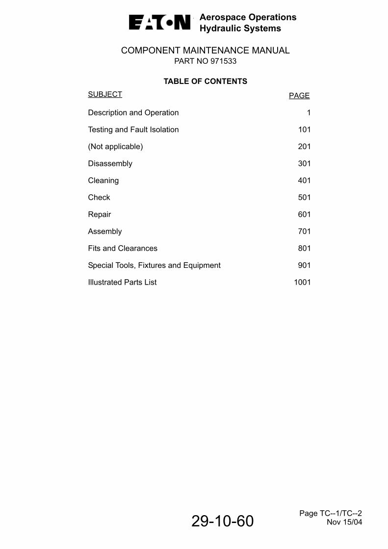
TABLE OF CONTENTSSUBJECT PAGE
Description and Operation 1
Testing and Fault Isolation 101
(Not applicable) 201
Disassembly 301
Cleaning 401
Check 501
Repair 601
Assembly 701
Fits and Clearances 801
Special Tools, Fixtures and Equipment 901
Illustrated Parts List 1001
Page TC--1/TC--2 Nov 15/04

Aerospace OperationsHydraulic Systems
COMPONENT MAINTENANCE MANUALPART NO 971533
INTRODUCTION
This publication is issued as a Component Maintenance Manual for HydraulicMotorpump Assembly, Part Number 971533 (Model Number MPEV3-008-6)manufactured by Eaton Aerospace, Hydraulics Systems Division, Jackson,Mississippi 39206. Throughout the remainder of this manual, this assembly will bereferred to as a motorpump assembly.
This publication establishes the requirements for acceptance testing, disassembly,cleaning, checking, repair and assembly of this hydraulic motorpump assembly. Anillustrated parts list is also included to provide a part number identification ofassembly components.This publication contains data converting U.S. Standardsystem of measurements to the metric system.Throughout this publication, metricequivalents (in parentheses) follow the U.S.Standard measurements.
The maintenance and test procedures contained in this publication have beenverified in actual shop practices at Eaton. These procedures should be used as aguide to develop the necessary skills for proper expedient maintenance of thesehydraulic motorpump assemblies. However some degree of flexibility is permissiblesince user experience will result in equally acceptable procedures to accomplish thesame end.
The assembly and test areas assigned for the repair and maintenance of thesehydraulic motorpump assemblies should be isolated from particle generatingequipment such as grinders, lapping machines, paint spray booths and sandblastingmachines. Adequate ventilation and good housekeeping practices should bemaintained at all times to assure minimum contamination.
Verification:
Testing/Fault Isolation: Sep 94Disassembly: Sep 94Assembly: Sep 94
Page INTRO-1/INTRO-2
29-10-60 Nov 15/08
Aerospace OperationsHydraulic Systems
COMPONENT MAINTENANCE MANUALPART NO 971533
DESCRIPTION AND OPERATION1. Description.
The hydraulic motorpump assembly consists of a DC electric motor driven variable displacement, hydraulic pump. The motorpump supplies fluid flow, as required, foroperation of aircraft hydraulic system components. Normal functions of the motor-pump, in an aircraft hydraulic system, is to provide auxiliary standby power duringflight and for system checkouts on the ground. See Fig. 1.
The pump section of the motorpump assembly consists of the following majorcomponent parts; a cylinder block (1, Fig. 2), nine piston and shoe subassemblies(2),valve block(3),yoke (4), yoke control springs (5), pressure compensator valve(6),shaft seal subassembly (7), mating ring (8), mounting flange (9), ball bearing (10),pump housing (11) and drive shaft (12).
The drive shaft (12) is supported in the pump by bearings (10 and 19). The cylinderblock is splined to the drive shaft and driven in rotation by the motor driven shaft. Thecylinderblock(1) is held against the valve block (3) valving face by the action ofspring(13).
Figure 1. Variable Displacement Hydraulic Motorpump Assembly
29-10-60 Page 1 Nov 15/04

Aerospace OperationsHydraulic Systems
COMPONENT MAINTENANCE MANUALPART NO 971533
Yoke (4) is supported in the mounting flange by two pintle bearings (14). The yokeswivels through an arc from 0° to maximum yoke angle. Yoke angle is controlledbymetered outlet fluid pressure acting on yoke control piston (15) and by yoke controlsprings (5) which oppose the metered outlet pressure. The piston and shoesubassemblies (2) are retained in the yoke by retainer (16), piston shoes retainingplate (17) and screws, and ride on the shoe bearing late (18) during drive shaftrotation.
Valve block (3), which contains the inlet and outlet ports, provides valving action todirect fluid flow to and from the cylinder block (1). The valve block also contains thepressure compensator valve (6), pressure adjusting screw (20) and needlebearing(19).
The mounting flange contains the yoke (4), seepage and case drain ports, shaft ballbearing (10), shaft seal subassembly (7) and mating ring (8).
The electric motor is a four-pole, compound-field dc motor designed specifically todrive the motorpump hydraulic pump. The motor is cooled internally by means of acooling fan directly driven by the motor shaft. Intake air is pulled through an openingequipped with a flame arrestor screen, and exhausted through a one inch (25.4 mm)O.D. port connected to outside air. Power is supplied to the motor through a RFI filteron the negative and positive leads. The purpose of the filter is to suppress radiofrequency noise that may try to escape from the motor into the system.
2. Operation.
Operation is fully automatic. The pump is designed to build up and maintain pressurewithout manual control. The pressure is maintained within a pre-adjusted range andis ready for instant use in the amount required within this range.
With electric motor operating, hydraulic fluid flows through the pump inlet port andvalve block (3, Fig. 2) valving slots, then into piston bores in cylinder block (1). Thecylinder block is driven by the drive shaft (12) in a rotary motion and the nine pistonand shoe subassemblies (2) are in turn driven by the cylinder block. At any outletpressure less than pressure adjustment setting, the yoke is moved to maximumdisplacement position by yoke control springs (5). In this position, the angle betweenyoke and centerline of the drive shaft creates a reciprocating movement of thepistons within the cylinder block bores during drive shaft rotation.
Inlet fluid enters the bores of the cylinder block on the outward stroke of the pistonsand is discharged through the outlet port on the inward stroke of pistons. This actionprovides acontinuous, non-pulsating flow of fluid to the hydraulic system.
Page 2
29-10-60 Nov 15/04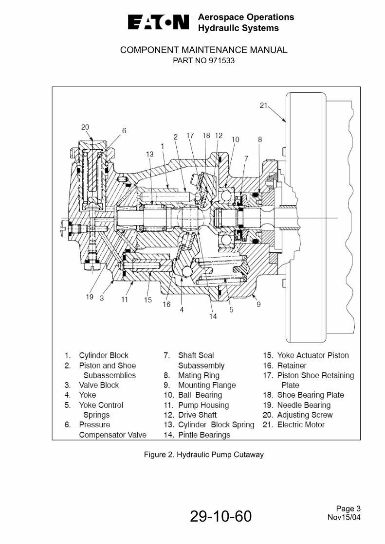
Aerospace OperationsHydraulic Systems
COMPONENT MAINTENANCE MANUALPART NO 971533
Figure 2. Hydraulic Pump Cutaway
Page 3
29-10-60 Nov15/04
Aerospace OperationsHydraulic Systems
COMPONENT MAINTENANCE MANUALPART NO 971533
Figure 3. Compensator Operation
Operation of the compensator valve is shown on Figure 3. With no load on the pumpthe yoke will be at maximum angle. As load increases, outlet pressure (Ps) increases.When (Ps) is sufficient to overcome the force of the compensator spring, thecompensator valve spool moves downward, metering increasing control pressure(Pc) to the yoke actuator piston. This causes the yoke angle to decrease. Decreasedyoke angle shortens the stroke of the pistons within the cylinder block bores andreduces outlet flow.
As outlet pressure (Ps) continues to increase, yoke angle and pump output flowcontinues to decrease. At or near maximum pressure, outlet fluid flow continues to bemetered through the pressure compensator to yoke actuator piston, until extension ofactuator piston moves the yoke to the ”zero flow” position. The yoke remains in the“zero flow” position until aircraft system demand for flow is initiated. Upon demand,outlet pressure decreases to a value that allows the yoke control springs to overridemetered fluid pressure (Pc) to the yoke actuator piston, this allows yoke angle andflow to increase as necessary to satisfy system demand.
29-10-60 Page 4 Nov 15/04

Aerospace OperationsHydraulic Systems
COMPONENT MAINTENANCE MANUALPART NO 971533
29-10-60
3. Leading Particulars:
Motorpump mounting positions Motorpump must be mounted inverted.Pump case drain connection must be connected directly to the reservoir in such a manner that the pump housing remains filled with hydraulic fluid during all operations. Pump internal parts depend on this fluid for lubrication. Mounting position must also be such that seep drain connection is at or near the 6 o’clock position. Pump case must be completely filled with fluid before operation.
Motorpump connections Provide a drain from seep drain connection Do not return seepage fluid to hydraulic system
Seep drain 0.4375-20 UNJF-3B thread (Per Specification MS33649-4)
Inlet 0.5625-18 UNJF-3B thread (Per Specification MS33649-6)
Outlet 0.4375-20 UNJF-3B thread (Per Specification MS33649-4)
Case drain 0.4375-20 UNJF-3B thread (Per Specification MS33649-4)
Electrical connectors
Motor MS3459L24-12P mates with MS3459L24-12S
Thermal switch MS3470L833P mates with MS3476L833S
Hydraulic Pump Characteristics:
Rated output flow (min) with 40 psia (276 kPa) (absolute) inlet pressure and 2750 psig (18 960 kPa) outlet
pressure. 1.5 gpm (5.7 l/m)
Theoretical displacement 0.050 cu. in/rev. (0.82 ml/rev)
Rated pressure at zero flow 2925 psig (20167 kPa)
Pressure rise as displacement is reduced to zero
150 psig (1034 kPa)
Page 5 Nov 15/04

Aerospace OperationsHydraulic Systems
COMPONENT MAINTENANCE MANUALPART NO 971533
29-10-60
Pressure at which displacement begins to reduce
2775 to 2825 psig (19133 to 19478 kPa)
Rated inlet pressure (min) 35 psia (241 kPa) (absolute)
Rated Speed-Full flow 7950 rpm
Zero flow 9300 rpm
Filtration requirements 10 micro (nominal)
Fluid temperature range -65°F to + 275°F (-54°C to +135°C)
Number of pistons 9
Direction of rotation (when viewed from motor end)
Counter clockwise
Coupling shaft spline dataMotor mating end 12 teeth, external involute, flat root, side fit,
32/64 pitch, 0.3750 pitch diameter, 30° pressure angle. 0.3960/ 0.3930 major diameter, 0.3335/0.3255 minordiameter.
Pump mating end 12 teeth, external involute, flat root, side fit,32/64 pitch, 0.3750 pitch diameter, 30° pressure angle. 0.3960/ 0.3930 major diameter 0.3335/0.3255 minor diameter.
Electric motor characteristics:
Direction of rotation (Viewing drive end)
Clockwise
Cooling Internal fan
Input voltage-VDC rated 28
VDC operating 20-32
Weight (motor only) 15.0 lbs. (8.2 kg)
Mounting pad AND 20000
Drive spline data 12 teeth, internal involute, flat root, side fit, 32/64 pitch, 0.3750 pitch diameter, 30° pressure angle, 0.4143/0.4063 major diameter, 0.3496/0.3466 min or diameter
Page 6 Nov 15/04
Aerospace OperationsHydraulic Systems
COMPONENT MAINTENANCE MANUALPART NO 971533
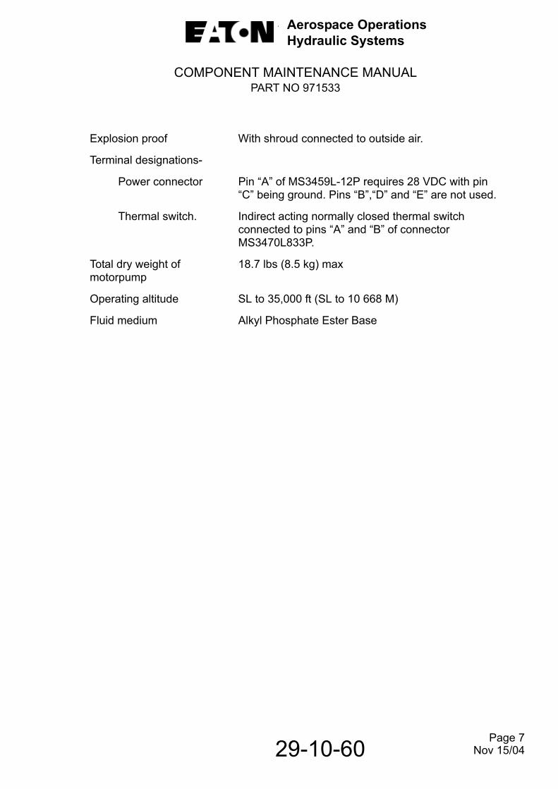
Explosion proof With shroud connected to outside air.
Terminal designations-
Power connector Pin “A” of MS3459L-12P requires 28 VDC with pin “C” being ground. Pins “B”,“D” and “E” are not used.
Thermal switch. Indirect acting normally closed thermal switch connected to pins “A” and “B” of connector MS3470L833P.
Total dry weight of motorpump
18.7 lbs (8.5 kg) max
Operating altitude SL to 35,000 ft (SL to 10 668 M)
Fluid medium Alkyl Phosphate Ester Base
Page 7
29-10-60 Nov 15/04
Aerospace OperationsHydraulic Systems
COMPONENT MAINTENANCE MANUALPART NO 971533
29-10-60
THIS PAGE LEFT BLANK INTENTIONALLY
Page 8 Nov 15/04

Aerospace OperationsHydraulic Systems
COMPONENT MAINTENANCE MANUALPART NO 971533
TESTING AND FAULT ISOLATION
1. Receiving Check.
WARNING: USE CLEANING SOLVENTS IN WELL VENTILATED AREA TO PREVENT INJURY. AVOID PROLONGED BREATHING OF FUMES. KEEP SOLVENTS AWAY FROM OPEN FLAME.
A. With all ports plugged, clean exterior of hydraulic motorpump assembly using drycleaning solvent P-D-680 (or equivalent) and a stiff bristle brush to remove anycontaminant that may have accumulated. Do not allow solvent to enter electricmotor. Air blow unit dry.
B. Visually check exterior for evidence of damage. If damage is noted and if damageis such that it will impair unit operation, refer to applicable paragraphs of overhaulsections for repair. If no external damage is noted, proceed with receiving check.
C. Remove case drain plug and drain unit. Collect discharged contents and check formetal particles. Presence of metal particles will not necessary mean deteriorationof unit but should be a warning to thoroughly check it before subjecting it toperformance tests.
D. If unit appears to be satisfactory after performing these preliminary procedures,perform as many operational tests as possible beginning with tests called for inparagraph 7. If it will pass all tests, return unit for a continuation of its timebetween overhaul period. If it will not, refer to Table 101 for repair proceduresbefore tagging unit for complete overhaul.
2. Special Tools.
Refer to SPECIAL TOOL, FIXTURES AND EQUIPMENT for a complete listing of special tools and test equipment recommended for maintenance of these motor- pump assemblies and a description of their function. Tooling and test equipment other than herein specified may be used provided they perform the required operation. Refer to the following table for tools and/or fixtures recommended for testing:
Page 101
29-10-60 Nov 15/08
Aerospace OperationsHydraulic Systems
COMPONENT MAINTENANCE MANUALPART NO 971533
Special Tools
3. Test Electric Motor Subassembly (Optional).
A. Test equipment shall include a 28 vdc power supply capable of 500 amperesstarting surge and regulated operation at 130 amperes sustained.
B. A precision dynamometer capable of operation at 25 pound inches (2.8 Nm)torque and at 7,950 rpm is required to load motor for test. A mating spline andcoupling is also required to adapt motor to dynamometer.
C. The test stand shall be equipped with suitable instrumentation to measure torque,speed, voltage and current. All equipment shall be certified to industry standards.
4. Test Conditions.
A. Motor brushes shall be seated 100% in the direction of rotation and 90% in theaxial direction.
B. The test load shall not be maintained for more than twenty (20) seconds with outallowing the motor to cool to room temperature.
CAUTION: DO NOT HI-POT FINAL MOTOR SUBASSEMBLY. INTERNALDAMAGE WILL OCCUR TO RFI FILTER CAPACITORS.
C. Direction of motor rotation shall be clockwise when viewed from drive end.
5. Acceptance Test.
The motor shall meet the following minimum performance criteria:
A. Load (Pound Inches/Nm) . . . . . . . . . . . . . . . . . . . . . . . . . . . . . . 25.0 (2.8)
B. RPM . . . . . . . . . . . . . . . . . . . . . . . . . . . . . . . . . . . . . . . . . . . . . . . . 7,950 ± 500
C. Current (Max. Amps., Continuous Operation) . . . . . . . . . . . . . 130
D. Voltage, VDC . . . . . . . . . . . . . . . . . . . . . . . . . . . . . . . . . . . . . . . . 20
T-233247 Flushing Set
T-442698 Test Plate
T-302537 A” Frame Test Stand
Local Manufacture (Refer to Description and Operation (Leading Particulars) for motor spline data)
Coupling Adapter(Adapt Dynamometer to Motor)
Page 102
29-10-60 Nov 15/08
Aerospace OperationsHydraulic Systems
COMPONENT MAINTENANCE MANUALPART NO 971533
6. Test Hydraulic Pump Subassembly (Optional).
A. Test Conditions.
(1) Use test equipment providing the arrangement shown in Fig. 101.
(2) Use a hydraulic test stand capable of supplying the following:
(a) Drive rotation, counterclockwise.
(b) Variable speed drive capable of developing a minimum of 20 horsepower(15 kw).
(c) Capable of measuring output speed to a maximum of 12,000 rpm.
(d) Capable of recording outlet pressure to a maximum of 4000 psig (27 579 kPa) and flow from zero to 2 gpm (7.6 L/m).
(e) Capable of providing inlet supercharge pressure of 25 psig (172 kPa).
(f) Capable of filtering test circuit fluid to a maximum of ten micron absolute.
(g) Capable of controlling inlet fluid temperatures of 160° ± 10°F (71° ±6°C).
(3) Maintain test conditions as follows, unless otherwise stated in the testinstructions:
(a) Maintain inlet fluid temperature at 160° ±10°F (71° ± 6°C).
(b) Maintain inlet pressure of 25 ± 5 psig (172 ± 34 kPa).
(c) Maintain case pressure of 15 ± 5 psig (103 ± 34 kPa) above inlet pressure
B. External Leakage.
(1) Shaft Seal.
Shaft seal shall not exceed two (2) drops per minute during all phases of testing.One drop is equal to approximately 1/20 ml.
(2) External Leakage.
External leakage other than a slight wetting insufficient to form a drop,through any seal or gasket (except shaft seal) shall be cause for rejection.
C. Preliminary Tests. Page 103
29-10-60 Nov 15/04
Aerospace OperationsHydraulic Systems
COMPONENT MAINTENANCE MANUALPART NO 971533
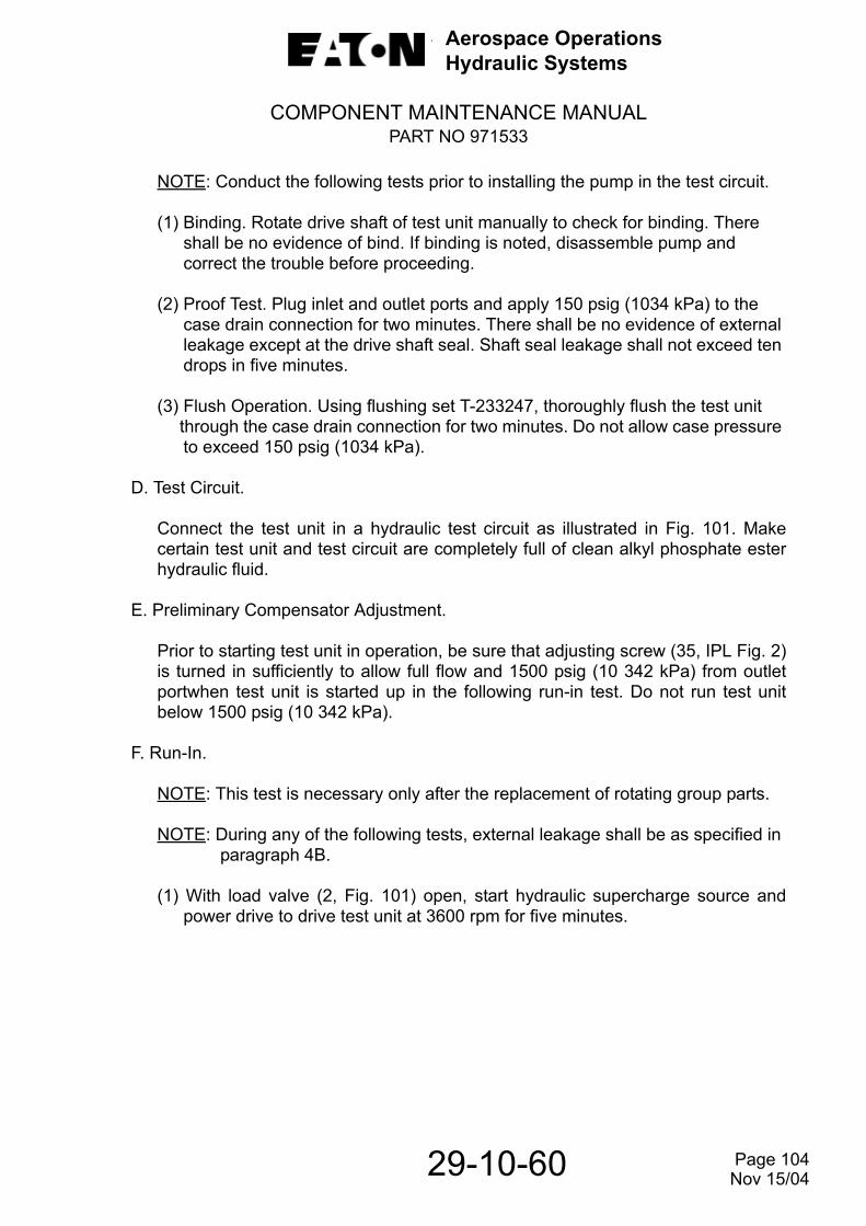
NOTE: Conduct the following tests prior to installing the pump in the test circuit.
(1) Binding. Rotate drive shaft of test unit manually to check for binding. There shall be no evidence of bind. If binding is noted, disassemble pump and correct the trouble before proceeding.
(2) Proof Test. Plug inlet and outlet ports and apply 150 psig (1034 kPa) to the case drain connection for two minutes. There shall be no evidence of external leakage except at the drive shaft seal. Shaft seal leakage shall not exceed ten drops in five minutes.
(3) Flush Operation. Using flushing set T-233247, thoroughly flush the test unit through the case drain connection for two minutes. Do not allow case pressure
to exceed 150 psig (1034 kPa).
D. Test Circuit.
Connect the test unit in a hydraulic test circuit as illustrated in Fig. 101. Makecertain test unit and test circuit are completely full of clean alkyl phosphate esterhydraulic fluid.
E. Preliminary Compensator Adjustment.
Prior to starting test unit in operation, be sure that adjusting screw (35, IPL Fig. 2)is turned in sufficiently to allow full flow and 1500 psig (10 342 kPa) from outletportwhen test unit is started up in the following run-in test. Do not run test unitbelow 1500 psig (10 342 kPa).
F. Run-In.
NOTE: This test is necessary only after the replacement of rotating group parts.
NOTE: During any of the following tests, external leakage shall be as specified in paragraph 4B.
(1) With load valve (2, Fig. 101) open, start hydraulic supercharge source andpower drive to drive test unit at 3600 rpm for five minutes.
29-10-60 Page 104 Nov 15/04

Aerospace OperationsHydraulic Systems
COMPONENT MAINTENANCE MANUALPART NO 971533
Pump Schematic Test SetupFigure 101 (Sheet 1 of 2)
Page 105
29-10-60 Nov 15/04
Aerospace OperationsHydraulic Systems
COMPONENT MAINTENANCE MANUALPART NO 971533
Pump Schematic Test SetupFigure 101 (Sheet 2 of 2)
INDEX NO NOMENCLATURE DESCRIPTION
1 Flow meter 0 to 2.0 gpm (0 to 7.6 L/m)
2 Load Valve Manual Control (high pressure)
3 Relief Valve Adjustable, Set at 3100 psig (21 374 kPa)
4 Filter High Pressure 10 micron (absolute), 3 gpm(11.4 L/m) capacity
5 Pressure Gage 0 to 4000 psig (0 to 27 579 kPa)
6 Pressure Gage 0 to 100 psig (o to 689 kPa)
7 Load Valve Manual Control (low pressure)
8 Relief Valve Adjustable, set at 50 psig (345 kPa
9 Shutoff Valve Manual Control (low pressure)
10 Beaker 2000 cc Capacity Graduated in 25 cc increments
11 Filter Low Pressure 10 micron (absolute), 3 gpm(11.4 L/m) capacity
12 Pressure Gage 0 to 100 psig (0 to 689 kPa)
13 Temperature Gage 32° to 200°F (0° to 93°C) Range
14 Filter Low Pressure 10 micron (absolute), 3 gpm(11.4 L/m) capacity
15 Supercharge Source Pump 0 to 50 psig (0 to 345 kPa) at 3 gpm (11.4 L/m) capacity
16 Test Stand 10 gal. (37.9 l) capacity Reservoir
17 Frequency (RPM) 0 to 12,000 rpm range Counter
18 Power Drive 20 horsepower (15 kw), variable to 12,000 rpm
29-10-60 Page 106 Nov 15/04

Aerospace OperationsHydraulic Systems
COMPONENT MAINTENANCE MANUALPART NO 971533
(2) Adjust supercharge pump (15) to provide inlet pressure of 25 ± 5 psig (172 ± 34 kPa) as indicated on inlet pressure gage (12).
(3) Close load valve (7) and adjust relief valve (8) to provide a case pressure of 15 ± 5 psig (103 ± 34 kPa) above inlet pressure as indicated on case pressure
gage (6).
(4) Gradually close load valve (2) to increase outlet pressure, as shown on pressure gage (5), from 1500 psig (10 342 kPa) to 2950 psig (20 340 kPa) and zero flow on flow meter (1) during the first five minutes.
(5) During the next five minutes, gradually increase speed to 9350 ± 50 rpm.
Continue at this speed and zero flow for five minutes. During this run-in, open shutoff valve (9) and measure case drain flow in beaker (10).
NOTE: Case drain flow at 9350 rpm and 2950 psig (20340 kPa) outletpressure shall not exceed 0.47 gpm (1780 cc/min.).
(6) During run-in observe unit for unusual noise or chatter. Stop test and investigate trouble observed.
G. Compensator Adjustment.
(1) With unit operating at 9350 ± 25 rpm and load valve (2) closed (zero flow),adjust compensator adjusting screw (35, IPL Fig. 2) to obtain 2900 + 50, - 0psig (19995 + 345, -0 kPa). Torque locking nut (30, IPL Fig. 2) 35 to 40 poundinches(4.0 to 4.5Nm).
NOTE: Make all pressure compensator settings on rising pressure.
(2) Alternately open and close load valve (2, Fig. 101) rapidly. This will purge anyair that may have become trapped in the compensator. After this operation,repeat step(1).
H. Pressure Shift.
(1) With unit operating at 9350 rpm, adjust load valve (2) to cycle from zero flow (2900 + 50, - 0 psig (19 995 + 345, -0 kPa) to 2700 + 50, -0 psig (19 995 +
345,-0kPa) to 2700 ± 50 psig (18 616 + 345, - 0 kPa) five times.
(2) Operate unit for three minutes at 9350 ± 25 rpm with zero delivery. Outlet pressure, as shown on pressure gage (5), shall not shift more than 25 psig (172 kPa) above or below pressure assumed at the time of shutoff.
I. Stability Check.
NOTE: During the following check, minimum time for the sweep shall be 60seconds from maximum to minimum speed and 60 seconds fromminimum to maximum speed.
Page 107
29-10-60 Nov 15/04
Aerospace OperationsHydraulic Systems
COMPONENT MAINTENANCE MANUAL PART NO 3032682-000
While operating test unit at zero flow (2900 + 50, - 0 psig (19 995 + 345, - 0 kPa),vary pump speed from 9350 rpm to 6000 rpm and back to 9350 rpm. There shallbe no indications of any persistent oscillations lasting more than one second.
J. Delivery Check.
(1) Reduce test unit speed to 7950 ±25 rpm.
(2) Adjust load valve (2) as necessary to obtain 2700 ± 50 psig (18 616 ± 345 kPa) on outlet pressure gage (5). Delivery of the pump shall not be less than 1.32 gpm(5.0 L/m) or greater than 1.72 gpm (5.5 L/m) as shown on flowmeter (1).
K. Case Flow Check.
(1) Continue to operate test unit at conditions established in paragraph 4J. Open shutoff valve (9) and measure case drain flow. Flow shall not exceed 0.22 gpm(835 cc/min).
(2) Operate test unit at 9350 ±25 rpm and 2900 + 50, - 0 psig (19 995 + 345, - 0 kPa) outlet pressure (zero flow). Measure case drain flow. Flow shall not exceed 0.47 gpm (1780 cc/min.).
L. Cylinder Block Lift Test.
NOTE: During the following tests monitor case drain leakage (flow) and outlet flow (delivery) to ascertain that cylinder block lift does not occur during acceleration and steady state conditions. Cylinder block lift will be indicated by high case drain leakage, low outlet flow (pump delivery) and pressure oscillations.
(1) Operate test unit at 9350 ± 25 rpm and reduce outlet pressure as low as possible (full flow).Record pressure for reference during test. Decelerate unit to zero rpm.
(2) Uniformly accelerate test unit to 10,300 rpm within two seconds. Continue to operate at low pressure and high speed for thirty seconds. There shall be no evidence of cylinder block lift.
M. Friction Test.
(1) After test unit has successfully passed all tests specified in this paragraph, hand torque required to turn pump drive shaft shall be measured. Breakaway torque shall not exceed 7.0 pound inches (0.8 Nm) and turning torque shall not exceed 4.0 pound inches (0.45 Nm).
Page 108
29-10-60 Nov 15/04

Aerospace OperationsHydraulic Systems
COMPONENT MAINTENANCE MANUALPART NO 971533
7. Test Motorpump Assembly.
CAUTION: A LIGHT SHALL BE INSTALLED (SEE FIG. 102) TO ALERT OPERATING PERSONNEL OF OVERTEMPERATURE CONDITION IN BRUSH AREA. IF OVERTEMPERATURE CONDITION IS EXPERIENCED THE TESTS SHALL BE DISCONTINUED UNTIL THE MOTOR HAS HAD ADEQUATE TIME TO COOL. THE THERMAL PROTECTION DEVICE FOR THE MOTOR IS LOCATED IN THE BRUSH AREA. THIS DEVICE IS NORMALLY CLOSED; THEREFORE,OVERTEMPERATURE CONDITION WILL BE INDICATED WHEN PILOT LIGHT GOES OFF DURING OPERATION.
CAUTION: ELECTRIC MOTOR IS NOT RATED FOR CONTINUOUS-DUTY AT FULL-FLOW (MAXIMUM CURRENT DRAW) CONDITIONS. MOTOR PUMP SHALL NOT BE OPERATED CONTINUOUSLY IN FULL FLOW FOR MORE THAN ONE (1) MINUTE.
A. Test Conditions.
Refer to paragraphs 3B and 4A. External leakage shall be as specified in paragraph 4B.
B. Test Equipment.
(1) Test equipment shall include a 28 vdc power supply capable of 500 amperes starting surge and 130 amperes sustaining.
(2) Test stand shall be equipped with suitable instrumentation to measure voltage and current, and pump test setup as shown in Fig. 102.
(3) MS3476L833S or equivalent connector to couple thermal switch and light to 28vdc power supply. MS3459L24-12S or equivalent connector is required for
motor power supply.
(4) The motorpump is oriented in an inverted position in the aircraft installation. If required, a fixture shall be locally manufactured to mount motorpump as shown in Fig. 102. The motor base mounting dimensions are shown in
Fig. 103.
C. Test Circuit.
Connect test unit into a test circuit as illustrated in Fig. 102. Be sure hydraulic pump and test circuit are completely full of clean alkyl phosphate ester hydraulic fluid.
29-10-60 Page 109 Nov 15/04

Aerospace OperationsHydraulic Systems
COMPONENT MAINTENANCE MANUALPART NO 971533
NOTE: Shock mounts shall not be installed on motor during test. Refer to DISASSEMBLY, paragraph 3B(3) for shock mount removal and to ASSEMBLY, paragraph 5A for reinstallation after test.
D. Break-In.
(1) Set power supply voltage at 28 vdc.
(2) Open load valve (2, Fig. 102), start hydraulic supercharge source (15) and adjust supercharged inlet pressure as shown on pressure gage (12) to 25 ± 5 psig (172 ± 34 kPa).
(3) Close load valve (7) and adjust relief valve (8) to provide a case drain pressure of 15 ± 5 psig (103 ± 34 kPa) above inlet pressure.
(4) Operate test unit for three minutes with load valve (2) adjusted to provide 0.3 gpm (1.1 L/m) as indicated on flowmeter (1). During this period, observe, motorpump for any unusual noise or indication of possible malfunction.
(5) Uniformly adjust load valve (2) to increase flow on flow meter (1) to obtain full flow pressure, (2700 ± 50 psig (18616 ± 345 kPa)) over a thirty second period. Operate at full flow for one minute.
E. Outlet Pressure Check.
(1) With test unit operating at 28 vdc, adjust load valve (2) for zero delivery (outlet flow) and check outlet pressure on gage (5). If pressure is not within
2900 + 50,-0 psig (19 995 + 345, - 0 kPa), adjust compensator adjusting screw (35, IPL Fig.2) as necessary to obtain zero delivery outlet pressure.
(2) Torque locking nut (30, IPL Fig. 2) 35 to 40 pound inches (4.0 to 4.5 Nm) and secure with lockwire MS20995C32.
Page 110
29-10-60 Nov 15/04
Aerospace OperationsHydraulic Systems
COMPONENT MAINTENANCE MANUALPART NO 971533
Motorpump Schematic Test SetupFigure 102 (Sheet 1 of 2)
Page 111
29-10-60 Nov 15/04
Aerospace OperationsHydraulic Systems
COMPONENT MAINTENANCE MANUALPART NO 971533
Motorpump Schematic Test SetupFigure 102 (Sheet 2 of 2)
INDEX NO. NOMENCLATURE DESCRIPTION1 Flow meter 0 to 2.0 gpm (0 to 7.6 L/m)2 Load Valve Manual Control (high pressure)
3 Relief Valve Adjustable, Set at 3100 psig (21 374 kPa)
4 Filter High Pressure 10 micron (absolute), 3 gpm(11.4 L/m) capacity
5 Pressure Gage 0 to 4000 psig (0 to 27 579 kPa)
6 Pressure Gage 0 to 100 psig (0 to 689 kPa)7 Load Valve Manual Control (low pressure)8 Relief Valve Adjustable, set at 50 psig(345 kPa)9 Shutoff Valve Manual Control (low pressure)10 Beaker 2000 cc Graduated in 25 cc increments
11 Filter Low Pressure 10 micron (absolute), 3 gpm(11.4 L/m) capacity
12 Pressure Gage 0 to 100 psig (0 to 689 kPa)13 Pressure Gage 32° to 200°F (0° to 93°C)
14 Filter Low Pressure 10 micron (absolute), 3 gpm(11.4 L/m) capacity
15 Supercharge 0 to 50 psig (0 to 345 kPa) at 3 gpm16 Source Pump (11. 4 L/m) capacity17 Reservoir 10 gal. (37.9 l) capacity
29-10-60 Page 112 Nov 15/04
Aerospace OperationsHydraulic Systems
COMPONENT MAINTENANCE MANUALPART NO 971533
Motorpump Mounting DimensionsFigure 103
F. Current Draw.
(1) With test unit operating at voltages, pressures and/or flows as specified in the following steps, measure parameters listed as follows:
(a) Amperage
(b) Outlet pressure
(c) Case drain flow
(d) Delivery (outlet flow)
(e) Inlet pressure
(2) Zero flow check- operate test unit at 28 vdc and zero flow (2900 + 50, -0 psig (19 995 + 345, - 0 kPa). Maximum current draw shall not exceed 65 amperes. Case flow shall not exceed 0.47 gpm (1780 cc/min.).
Page 113
29-10-60 Nov 15/04
Aerospace OperationsHydraulic Systems
COMPONENT MAINTENANCE MANUALPART NO 971533
(3) Full flow check-operate test unit at 28 vdc and full flow (2700 ± 50 psig (18 616 ± 345 kPa). Full flow delivery shall not be less than 1.32 gpm (5.0 L/m)
or greater than 1.72 gpm (6.5 L/m). Maximum current draw shall not exceed 130 amperes. Case drain flow shall not exceed 0.22 gpm (835 cc/min.).
G. Test Completion.
After satisfactory testing, proceed as follows:
(1) Remove test unit from test setup.
(2) Drain pump of test fluid and flush unit.
NOTE: Pump must be filled with fluid for corrosion prevention. Fluid from test stand can be used if cleanliness exceeds SAE AS4059, Class 7 level. If.teststand fluid cleanliness levels are not maintained, flush and fill with clean fluid.
(3) Be sure sealing screws (20, IPL Fig. 2) and locking nut (30) are secured with lockwire.
(4) Prepare motorpump for shipment or storage as instructed in ASSEMBLY,paragraph 6.
8. Fault Isolation.
The following fault isolation chart, Table101, has been prepared to assist personnel in locating cause for malfunction of the unit. It lists troubles, probable cause of each, and the necessary remedial steps.
Page 114
29-10-60 Nov 15/04
Aerospace OperationsHydraulic Systems
COMPONENT MAINTENANCE MANUALPART NO 971533
Fault Isolation and Repair Procedure ChartTable 101 (Sheet 1 of 6)
ITEMNO. TROUBLE PROBABLE CAUSE REMEDY
1 Electric motor inoperative
No electric input. Provide required input power to electric motor connector. Refer toTESTING
2 Pump not delivering (with electric motoroperating
Inlet to test unit blocked or insufficient fluid in hydraulic circuit.
Remove restriction from hydrauliclines. Maintain correct fluid level in reservoir.
Inlet pressure to test unit too low.
Provide required inlet pressure test unit. Refer to TESTING.
Yoke stuck in minimum flow position.
Remove pump housing (135, IPL Fig. 2) and check movement ofcontrol piston (140). Piston shallmove freely in pump housing.Correct any malfunction andreassemble unit.
Electric motor not wired for proper rotation.
Check correct wiring of electric motor. Refer to Fig. 702.
3 Electric motor overheating or drawing current in excess of 130 amps.
Insufficient heat dissipation in hydraulic circuit
Assure inlet fluid temperature does not exceed value specified in TESTING.
Insufficient electric power to motor.
Provide required electrical power input to motor connector specified in TESTING.
Insufficient clearance for pis-ton and shoe subassemblies(210, IPL Fig. 2).
Disassemble pump componentscheck piston and shoe clearance Refer to ASSEMBLY. Correct mal-function and re-assemble unit.
29-10-60 Page 115 Nov 15/04
Aerospace OperationsHydraulic Systems
COMPONENT MAINTENANCE MANUALPART NO 971533
Fault Isolation and Repair Procedure ChartTable 101 (Sheet 2)
ITEMNO. TROUBLE PROBABLE CAUSE REMEDY
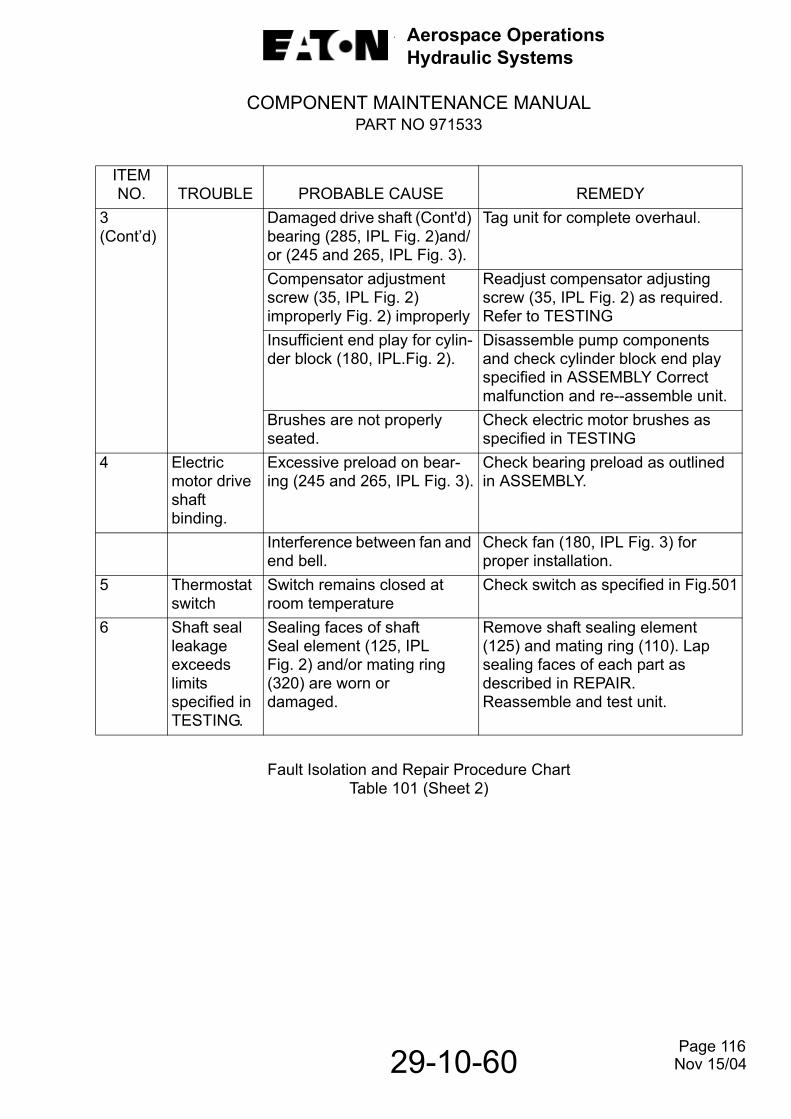
3(Cont’d)
Damaged drive shaft (Cont'd) bearing (285, IPL Fig. 2)and/or (245 and 265, IPL Fig. 3).
Tag unit for complete overhaul.
Compensator adjustment screw (35, IPL Fig. 2) improperly Fig. 2) improperly
Readjust compensator adjusting screw (35, IPL Fig. 2) as required. Refer to TESTING
Insufficient end play for cylin-der block (180, IPL.Fig. 2).
Disassemble pump components and check cylinder block end play specified in ASSEMBLY Correct malfunction and re--assemble unit.
Brushes are not properly seated.
Check electric motor brushes as specified in TESTING
4 Electric motor drive shaft binding.
Excessive preload on bear-ing (245 and 265, IPL Fig. 3).
Check bearing preload as outlined in ASSEMBLY.
Interference between fan and end bell.
Check fan (180, IPL Fig. 3) for proper installation.
5 Thermostatswitch
Switch remains closed at room temperature
Check switch as specified in Fig.501
6 Shaft seal leakage exceeds limits specified in TESTING.
Sealing faces of shaft Seal element (125, IPL Fig. 2) and/or mating ring (320) are worn or damaged.
Remove shaft sealing element (125) and mating ring (110). Lap sealing faces of each part as described in REPAIR. Reassemble and test unit.
Page 116
29-10-60 Nov 15/04
Aerospace OperationsHydraulic Systems
COMPONENT MAINTENANCE MANUALPART NO 971533
Fault Isolation and Repair Procedure ChartTable 101 (Sheet 3)
ITEMNO. TROUBLE PROBABLE CAUSE REMEDY
6(Contd)
Shaft seal wave spring (145, IPL Fig. 2) compression relaxed.
Remove wave spring and test part as specified in Fig. 501 and 801. Correct malfunction and reassemble unit
7 Low outlet flow
Insufficient electrical power to trical power to
Provide proper electrical power input. Refer to TESTING
Pressure control not properly set, allowing yoke to move to zero flow position before fullvolume and pressuredevelops.
Readjust pressure compensator as specified in TESTING.
Spool (70,IPL Fig. 2) not operating freely in valve block (60).
Remove pilot valve and check for freedom of movement in valve bore.If necessary, lap as specified in Fig. 501. Reassemble unit aftercorrection of malfunction.
Actuator piston (175, IPL Fig.2)not operating freely in housing bores
Remove pump housing (155, IPL Fig. 2) and check for freedom of movement of actuator piston. Refer to Fig. 801 for clearance require-ment. Correct malfunction and reas-semble unit
Page 117
29-10-60 Nov 15/04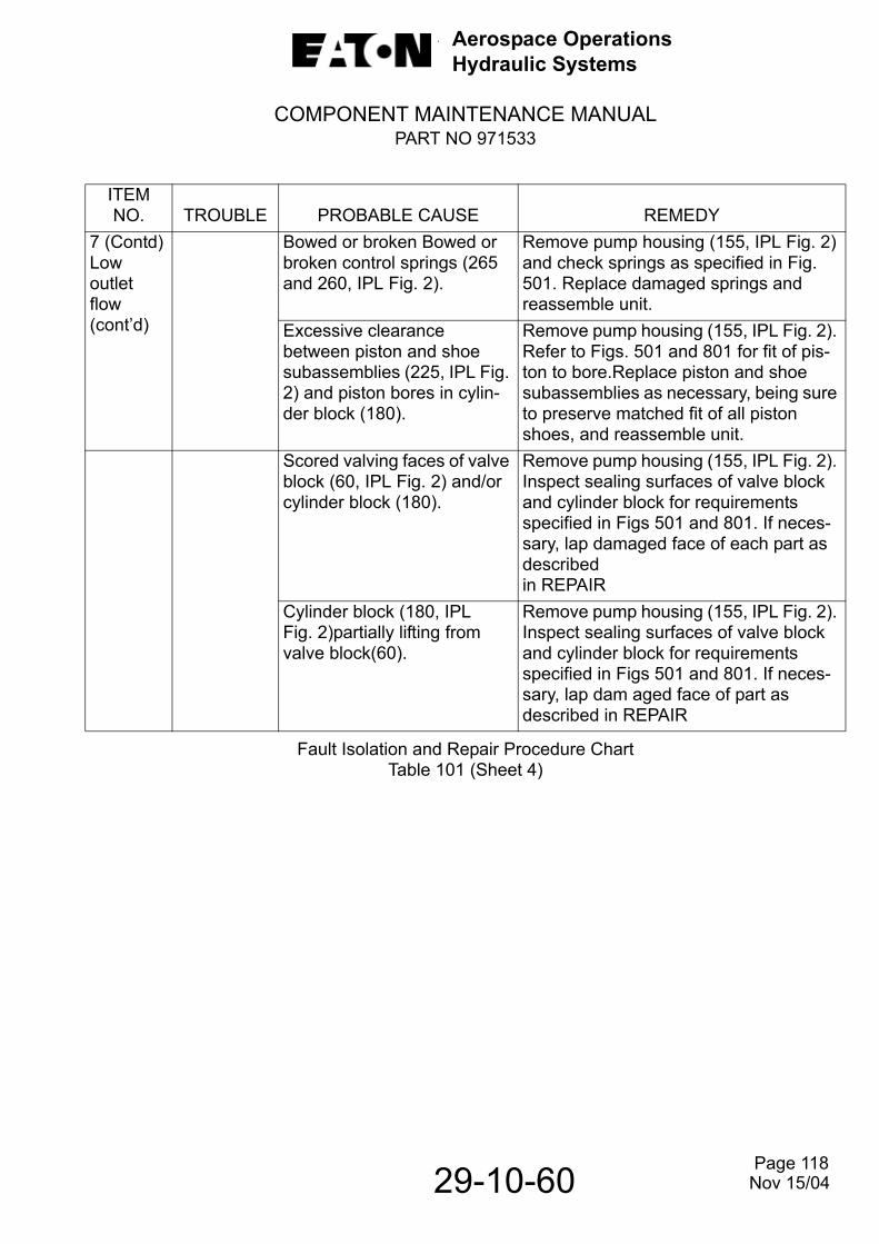
Aerospace OperationsHydraulic Systems
COMPONENT MAINTENANCE MANUALPART NO 971533
7Lof(
Fault Isolation and Repair Procedure ChartTable 101 (Sheet 4)
ITEMNO. TROUBLE PROBABLE CAUSE REMEDY
(Contd)ow utlet
lowcont’d)
Bowed or broken Bowed or broken control springs (265 and 260, IPL Fig. 2).
Remove pump housing (155, IPL Fig. 2) and check springs as specified in Fig. 501. Replace damaged springs and reassemble unit.
Excessive clearance between piston and shoe subassemblies (225, IPL Fig. 2) and piston bores in cylin-der block (180).
Remove pump housing (155, IPL Fig. 2). Refer to Figs. 501 and 801 for fit of pis-ton to bore.Replace piston and shoe subassemblies as necessary, being sure to preserve matched fit of all piston shoes, and reassemble unit.
Scored valving faces of valve block (60, IPL Fig. 2) and/or cylinder block (180).
Remove pump housing (155, IPL Fig. 2). Inspect sealing surfaces of valve block and cylinder block for requirements specified in Figs 501 and 801. If neces-sary, lap damaged face of each part as describedin REPAIR
Cylinder block (180, IPL Fig. 2)partially lifting from valve block(60).
Remove pump housing (155, IPL Fig. 2). Inspect sealing surfaces of valve block and cylinder block for requirements specified in Figs 501 and 801. If neces-sary, lap dam aged face of part as described in REPAIR
Page 118
29-10-60 Nov 15/04
Aerospace OperationsHydraulic Systems
COMPONENT MAINTENANCE MANUALPART NO 971533
Fault Isolation and Repair Procedure ChartTable 101 (Sheet 5)
ITEMNO. TROUBLE PROBABLE CAUSE REMEDY
8 Pressure creeps more than ± 25 psig (± 172 kPa) with yoke zero flow (2900 psig(19 995 kPa)).
Trapped air in test circuit and/or pressure compensator
Bleed all air from test circuit and test unit.
Sticky operation of actuator piston (175,IPL Fig. 2).
Remove pump housing (155, IPL Fig. 2) and check for freedom of movement of actuator piston. Refer to Figs. 501 and 801 for clearance requirements. Correct malfunction and reassemble unit.
Case drain pressure varies during test period
Maintain constant case drain pres-sure during test period.
9 Excessive internal leakage. (Case flow exceeds limits specified in test).
Excessive clearance between piston and shoe subassemblies (225, IPL Fig. 2) and piston bores in cylin-der block (180).
Remove pump housing (155, IPL Fig. 2). Refer to Figs. 501 and 801 for fit of piston to bore. Replace pis-ton and shoe subassemblies as necessary, being sure to preserve match fit of all piston shoes, and reassemble unit
Scored valving faces of valve block (60, IPL Fig. 2) and/or cylinder block(180)
Remove pump housing (155, IPL Fig. 2). Inspect sealing surfaces of valve plate and cylinder block for requirements specified in Figs 501 and 801. If necessary, lap damaged face of each part asdescribed in REPAIR
Page 119
29-10-60 Nov 15/04
Aerospace OperationsHydraulic Systems
COMPONENT MAINTENANCE MANUALPART NO 971533
Fault Isolation and Repair Procedure ChartTable 101 (Sheet 6)
ITEMNO. TROUBLE PROBABLE CAUSE REMEDY
9(contd)
Cylinder block (180, IPL Fig.2)partially lifting from valveblock (60)
Remove pump housing (155, IPL Fig. 2). Inspect sealing surfaces of valve block and cylinder block for requirements specified in Figs.501 and 801. If necessary, lap damaged face of part as described inREPAIR
10 Outlet pressurefluctuation.
Trapped air in test circuit and/or pressure control
Bleed trapped air. Refer to TEST.
Foreign matter in pressurecompensator.
Disassemble pressure compensatorand clean parts. Refer to CLEANING.
Burr on spool (70, IPL Fig. 2) and/or valve block(60).
Disassemble pressure compensatorand remove burrs.
Sticky actuator piston (175,IPL Fig.2)
Remove control piston and check for clearance and surface finish as specified in Figs. 501 and 801.
Cylinder block (180, IPL Fig. 2) partially lifting romvalve block(60)
Remove pump housing (155, IPL Fig. 2). Inspect sealing surfaces of valve block and cylinder block for requirements specified in Figs.. 501 and 801. If necessary, lap damaged face of part as described inREPAIR.
Page 120
29-10-60 Nov 15/04
Aerospace OperationsHydraulic Systems
COMPONENT MAINTENANCE MANUALPART NO 971533
9. Test Record.
Remove test record pages and make a copy of the pages, replace originals into manual.Initial or record information as requested. Attach completed record to pump and place acopy of completed test record in the history file of the pump.
29-10-60 Page 121 Nov 15/04

Aerospace OperationsHydraulic Systems
COMPONENT MAINTENANCE MANUALPART NO 971533
TEST RECORDDate: Assembly No.:Model: Test OperatorModel Name: Fluid Used:Serial No.: Test Stand No.:Customer No.: Q.A. Acceptance:Work Order:Para Test Performed Limits Actual Data33.A.,B & C
4
5
Test Electric MotorSubassembly (Optional)Test setup, see Para 3. _______ComplyTest Conditions,see Para 4. _______Comply
CAUTION: DO NOT HI-POT FINAL MOTOR SUBASSEMBLY. INTERNAL DAMAGE WILL OCCUR TO RFI FILTER CAPACITORS
Acceptance Test:The motor shall meet thefollowing minimum RPM:Performance criteria:
Load: 25.0 lbs. in. (2.8 N.m)7,950 ±500Current: 130 amps max.Voltage: 20 vdc
_______Accept_______Accept_______Accept_______Accept
6 Test hydraulic PumpSubassembly (Optional).
6.A. Test Conditions.See para 6A (1) thru (3)
______Comply
6.B. External Leakage.6.B.(1) Shaft Seal. Shaft Seal shall not exceed
two (2) drops per minuteduring all phases of testing.One drop is equal toapproximately 1/20 ml.
______Accept
6.B.(2) External Leakage. External leakage other than a slight wetting insufficient to form a drop, through andy seal or gasket (except shaft seal) shall be cause for rejection.
______Accept
Test Record Table 102 (Sheet 1 of 8)
29-10-60 Page 122
Nov 15/08

Aerospace OperationsHydraulic Systems
COMPONENT MAINTENANCE MANUALPART NO 971533
Test RecordTable 102 (Sheet 2)
Para Test Performed Limits Actual Data
6.C
6.C(1)
6.C(2)
6.C(3)
Preliminary Tests.NOTE: Conduct the following tests prior to installing the pump in the test
circuit.Binding. Rotate drive shaft of test unit manually to psig (1034 kPa) to the case drain connection for two minutes.
If binding is noted, disassemble pump and correct the trouble before proceeding
____Accept
Proof Test. Plug inlet and outlet ports and apply 150 psig (1034 kPa) to the case drain connection for two minutes.
There shall be no evidence of external leakage except at the drive shaft seal. Shaft seal leakage shall not exceed ten drops in five minutes.
____Accept
Test Circuit. ____Accept
6.D Connect the test unit in a hydrau-lic test circuit as illustrated in Fig. 101. Make certain test unit and test circuit are completely full of clean phosphate ester hydraulic fluid or equivalent
___ Comply
6.E Preliminary CompensatorAdjustment.
____Accept
Prior to starting test unit in opera-tion, be sure that adjusting screw (35, IPL Fig.2) is turned in suffi-ciently to allow:
Full flow and 1500 psig (10 342 kPa) from outlet port when test unit is started up in the following run-in test. Do not run test unit below 1500 psig (10 342 kPa)
Page 123
29-10-60 Nov 15/04
Aerospace OperationsHydraulic Systems
COMPONENT MAINTENANCE MANUALPART NO 971533
Test RecordTable 102 (Sheet 3)
Para Test Performed Limits Actual Data
6.F Run-In.NOTE: During any of the following tests, external leakage shall be as
specified in paragraph 4B6.F(1)
6.F(2)
6.F(3)
6.F(4)
6.F(5)
6.F(6)
With load valve (2, Fig. 101) open, start hydraulic super-charge source and power drive to drive test unit at:
3600 rpm for five minutes. ___Comply
Adjust supercharge pup (15) to provide inlet pressure
25 ± 5 psig (172 ± 34 kPa)as indicated on inletpressure gage (12).
___Comply
Close load valve (7) and adjust relief valve (8) to provide a case pressure of:
15 ± 5 psig (103 ± 34 kPa) above inlet pressure as indicated on case pressuregage (6).
___Comply
Gradually close load valve (2) to increase outlet pressure, as shown on pressure gage (5), from:
1500 psig (10 342 kPa) to 2950 psig (20 340 kPa) and zero flow on flowmeter (1) during the first five minutes
___Comply
During the next five minutes, gradually increase speed to 9350 ± 50 rpm. Continue at this speed and zero flow for five minutes
During this run-in, open shut-off valve (9) and measure case drain flow in beaker (10).
___Comply
NOTE: Case drain flow at 9350 rpm and 2950 psig (20340 kPa)outlet pressure shall not exceed 0.47 gpm (1780 cc/min.).
During run-in observe unit for unusual noise or chatter
Stop test and investigate trouble observed.
___Comply
6.G Compensator Adjustment.
6.G(1) With unit operating at 9350 ± 25 rpm and load valve (2) closed (zero flow), adjust compensator adjusting screw (35, IPL Fig. 2) to obtain:
2900 + 50, - 0 psig (19 995 + 345, - 0 kPa). Torque locking nut (30, IPL Fig. 2) 35 to 40 pound inches (4.0 to 4.5 Nm).
___Comply
29-10-60 Page 124 Nov 15/04
Aerospace OperationsHydraulic Systems
COMPONENT MAINTENANCE MANUALPART NO 971533
Test RecordTable 102 (Sheet 4)
Para Test Performed Limits Actual Data
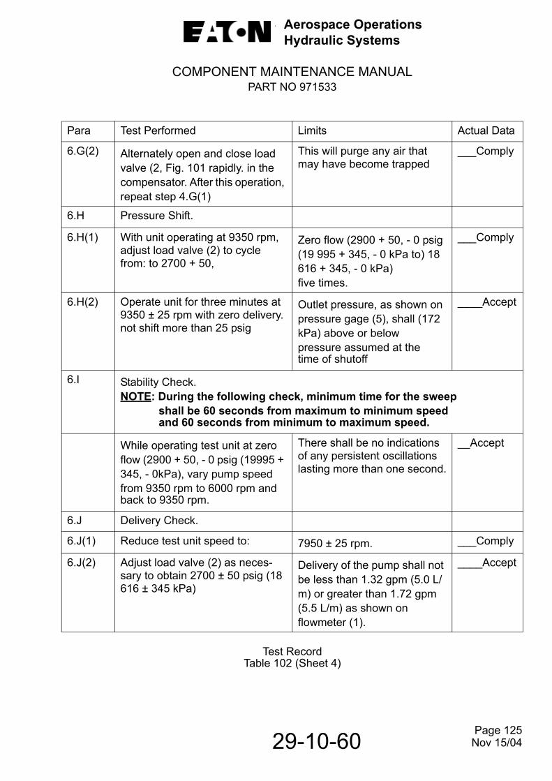
6.G(2) Alternately open and close load valve (2, Fig. 101 rapidly. in the compensator. After this operation, repeat step 4.G(1)
This will purge any air that may have become trapped
___Comply
6.H Pressure Shift.
6.H(1) With unit operating at 9350 rpm, adjust load valve (2) to cycle from: to 2700 + 50,
Zero flow (2900 + 50, - 0 psig (19 995 + 345, - 0 kPa to) 18 616 + 345, - 0 kPa)five times.
___Comply
6.H(2) Operate unit for three minutes at 9350 ± 25 rpm with zero delivery. not shift more than 25 psig
Outlet pressure, as shown on pressure gage (5), shall (172 kPa) above or belowpressure assumed at thetime of shutoff
____Accept
6.I Stability Check.NOTE: During the following check, minimum time for the sweep
shall be 60 seconds from maximum to minimum speedand 60 seconds from minimum to maximum speed.
While operating test unit at zero flow (2900 + 50, - 0 psig (19995 + 345, - 0kPa), vary pump speed from 9350 rpm to 6000 rpm andback to 9350 rpm.
There shall be no indications of any persistent oscillations lasting more than one second.
__Accept
6.J Delivery Check.
6.J(1) Reduce test unit speed to: 7950 ± 25 rpm. ___Comply
6.J(2) Adjust load valve (2) as neces-sary to obtain 2700 ± 50 psig (18 616 ± 345 kPa)
Delivery of the pump shall not be less than 1.32 gpm (5.0 L/m) or greater than 1.72 gpm (5.5 L/m) as shown on flowmeter (1).
____Accept
Page 125
29-10-60 Nov 15/04
Aerospace OperationsHydraulic Systems
COMPONENT MAINTENANCE MANUALPART NO 971533
Test RecordTable 102 (Sheet 5)
Para Test Performed Limits Actual Data
6.K Case Flow Check. ____Accept
6.K(1) Continue to operate test unit at conditions established in paragraph 4.J. Open shutoff valve (9) and measure case drain flow.
Flow shall not exceed 0.22 gpm (835 cc/min).
____Accept
6.K(2) Operate test unit at 9350 ± 25 rpm and 2900 + 50, - 0 psig (19 995 + 345, - 0 kPa) gpm.outlet pressure (zero flow).
____Accept
6.L Cylinder Block Lift Test.NOTE: During the following tests monitor case drain leakage (flow) and
outlet flow (delivery) to ascertain that cylinder block lift does not occur during acceleration and steady state conditions. Cylinder block lift will be indicated by high case drain leakage, low outlet flow (pump delivery) and pressure oscillations.
6.L(1) Operate test unit at 9350 ± 25 rpm and reduce outlet pressure as low as possible (full flow).
Record pressure for refer-ence during test Decelerate unit to zero rpm.
___Comply
6.L(2) Uniformly accelerate test unit to 10,300 rpm within two seconds. Continue to operate at low pressure and high speed for thirty seconds.
There shall be no evidence of cylinder block lift.
____Accept
6.M Friction Test.After test unit has passed all tests specified in this paragraph, hand torque required to turn pump drive shaft shall be mea-sured
Breakaway torque shall not exceed 7.0 pound inches (0.8 Nm) and turning torque shall not exceed 4.0 pound inches (0.45 Nm).
____Accept
Page 126
29-10-60 Nov 15/04
Aerospace OperationsHydraulic Systems
COMPONENT MAINTENANCE MANUALPART NO 971533
Test RecordTable 102 (Sheet 6)
Para Test Performed Limits Actual Data
7. Test Motorpump Assembly.CAUTION: A LIGHT SHALL BE INSTALLED (SEE FIG. 102) TO ALERT
OPERATING PERSONNEL OF OVERTEM PERATURE CONDITION IN BRUSH AREA. IF OVERTEMPERATURE CONDITION IS EXPERIENCED THE TESTS SHALL BE DISCONTINUED UNTIL THE MOTOR HAS HAD ADEQUATE TIME TO COOL. THE THERMAL PROTECTION DEVICE FOR THE MOTOR IS LOCATED IN THE BRUSH AREA. THIS DEVICE IS NORMALLY CLOSED; THEREFORE, OVERTEMPERATURE CONDITION WILL BE INDICATED WHEN PILOT LIGHT GOES OFF DURING OPERATION.
CAUTION: ELECTRIC MOTOR IS NOT RATED FOR CONTINUOUS- DUTY AT FULL-FLOW (MAXIMUM CURRENT DRAW) CONDITIONS. MOTOR-PUMP SHALL NOT BE OPERATED CONTINUOUSLY IN FULL-FLOW FOR MORE THAN ONE (1) MINUTE.
7.A Test Conditions.Refer to paragraphs 3B and 4A. External leakage shall be as specified in paragraph 6.B
___Comply
7.B Test Equipment.Refer to paragraph 7.B
___Comply
7.C Test Circuit.Connect test unit into a test circuit as illustrated in Fig.102. Be sure hydraulic pump and test circuit are completely full of clean phosphate ester hydraulic fluid
___Comply
NOTE: Shock mounts shall not be installed on motor during test.
Refer to DISASSEMBLY, paragraph 3B(3) for shock mount removal and to ASSEMBLY, paragraph 5A for reinstallation after test.
Page 127
29-10-60 Nov 15/08
Aerospace OperationsHydraulic Systems
COMPONENT MAINTENANCE MANUALPART NO 971533
Test RecordTable 102 (Sheet 7)
Para Test Performed Limits Actual Data
7.D
7.D(1)
7.D(2)
7.D(3)
7.D(4)
7.D(5)
Break-In.
Set power supply voltage at: 28 vdc. ___Comply
Open valve (2, Fig. 102),start hydraulic supercharge source (15) and adjust supercharged inlet pressure as shown on pressure gage (12) to:
25 ± 5 psig (172 ± 34 kPa). ___Comply
Close load valve (7) and adjust relief valve (8) to provide a case drain pressure of:
15 ± 5 psig (103 ± 34 kPa) above inlet pressure.
___Comply
Operate test unit for three minutes with load valve (2) adjusted to provide 0.3 gpm (1.1 L/m) as indicated on flowmeter (1).
During this period, observemotorpump for any unusualnoise or indication of possiblemalfunction
___Accept
Uniformly adjust load valve (2) to increase flow on flowmeter (1) to obtain full flow pressure, (2700 ± 50 psig (18 616 ± 345 kPa))over a thirty second period
Operate at full flow for oneminute.
___Comply
7.E
7.E(1)
7.E(2)
Outlet Pressure Check.
With test unit operating a 28 vdc, adjust load valve (2) for zero delivery (outlet flow) and check outlet pressure on gage (5).
If pressure is not within 2900 + 50, -0 psig (19 995 + 345,-0 kPa), adjust compensator adjusting screw (35, IPL Fig2) as necessary to obtain zero delivery outlet pressure.
____Accept
Torque locking nut (30, IPL Fig. 2). to 4.5 Nm).Secure with lockwire MS20995C32.
35 to 40 pound inches (4.0 ___Comply
___Comply
29-10-60 Page 128
Nov 15/04

Aerospace OperationsHydraulic Systems
COMPONENT MAINTENANCE MANUALPART NO 971533
Test RecordTable 102 (Sheet 8)
Para Test Performed Limits Actual Data
7.F
7.F(1)
7.F(2)
7.F(3)
Current Draw.
With test unit operating at voltages, pressures and/or flows as specified in the following steps, measure parameters listed as follows
(a) Amperage (b) Outlet pressure(c) Case drain flow(d) Delivery (outlet flow)(e) Inlet pressure
Zero flow check-operate test unit at 28 vdc and zero flow (2900 + 50, - 0 psig (19 995 + 345, - 0 kPa).
Maximum current draw shall not exceed 65 amperes.
___Accept
Case flow shall not exceed 0.47 gpm (1780 cc/min.).
___Accept
Full flow check- operate test unit at 28 vdc and full flow (2700 ± 50 psig (18 616 ± 345 kPa).
Full flow delivery shall not be less than 1.32 gpm (5.0 L/m) or greater than 1.72 gpm(5.5L/m)
___Accept
Maximum current draw shall not exceed 130 amperes.
____Accept
Case drain flow shall not exceed 0.22 gpm (835cc/min.).
____Accept
7.G Test Completion.After satisfactory testing,proceed as follows:
(1) Remove test unit from test setup and install shockmounts as instructed inASSEMBLY paragraph 5A.
___Comply
(2) Drain pump of test fluid and flush unit
___Comply
(3) Be sure sealing screws (20, IPL Fig. 2) and lockingnut (30) are secured withlockwire.
___Comply
(4) Prepare motorpump for shipment or storage asinstructed in ASSEMBLY,paragraph 6.
___Comply
Page 129
29-10-60 Nov 15/04
Aerospace OperationsHydraulic Systems
COMPONENT MAINTENANCE MANUALPART NO 971533
29-10-60
THIS PAGE LEFT BLANK INTENTIONALLY
Page 130 Nov 15/04

Aerospace OperationsHydraulic Systems
COMPONENT MAINTENANCE MANUALPART NO 971533
DISASSEMBLY1. General.
See TESTING AND FAULT ISOLATION for operational test and fault isolation toestablish the condition of the unit or the most probable cause of malfunction. This isto determine the extent of disassembly required without completely tearing down andrebuilding the unit.
2. Special Tools.
See SPECIAL TOOLS, FIXTURES AND EQUIPMENT for a complete list of special tools and test equipment recommended for maintenance of these hydraulic motorpump assemblies and a description of their function. Tooling and test equipment other than herein specified may be used provided they perform the required operations. Refer to following table for special tools recommended for disassembly.
List of Special ToolsTable 301
NOTE: Always use the proper tool for the job. Be sure wrenches fit properly onnutsor bolt heads. Do not use pliers to remove nuts or bolts. Do not usescrewdrivers to separate mating parts. Use a soft faced rod or mallet fortapping around binding area.
3. Disassemble Motorpump Assembly.
NOTE: The abbreviation IPL refers to the ILLUSTRATED PARTS LIST of this manual.Refer to IPL Fig. 1 for disassembly of hydraulic motorpump assembly.
NOTE: Discard all packings and backup rings removed during disassembly operations.
T-300664 Mechanical Positioner Adapter
T-304103 Bearing Removal Plate
T-304104 Bearing Driver
T-304105 Bearing Puller
T-304106 Holding Clamp
T-304165 Bearing Puller
T-443364 Assembly Fixture
T-443827 Spring Compressing Tool
Page 301
29-10-60 Nov 15/04
Aerospace OperationsHydraulic Systems
COMPONENT MAINTENANCE MANUALPART NO 971533
A. Prepare for Disassembly.
WARNING: CARE SHALL BE TAKEN IN THE REMOVAL OF LOCKWIRE. FORCEFULLY PULLING WIRE OUT OF RETAINED PARTS MAY CAUSE PERSONAL INJURY.
(1) Remove external lockwire.
(2) Remove outlet plug (325, IPL Fig. 2), seep plug (335) and case drain plug (345) and packings (330, 340 and 350).
(3) Remove inlet plug (355) and packing (360). Drain all hydraulic fluid from pump.
B. Disassembly.
(1) Remove nuts (10, IPL Fig. 1) and washers (15) securing hydraulic pump (5) toelectric motor (50).
(2) Carefully separate pump from motor and remove gasket (20).
CAUTION: DURING REMOVAL OF SHOCK MOUNT SUBASSEMBLIES (25),HOLD MOUNT (45) BY WRENCHING FLATS TO PREVENT INTERNAL DAMAGETO SHOCK MOUNT.
(3) Remove nuts (30) and washers (35) securing shock mount subassemblies tomotor footing.
(4) Do not disassemble shock mount subassemblies (25) unless replacement stud(40) or shock (45) is necessary.
(5) Do not remove identification plate (55) unless replacement is necessary. If replacement is necessary, refer to REPAIR.
4. Disassemble Hydraulic Pump Subassembly.
NOTE:Refer to IPL Fig. 2 for disassembly of hydraulic pump.
A. Remove Coupling Shaft.
(1) Grasp coupling shaft (5, IPL Fig. 2) and pull straight out.
(2) Remove packing (10) and retaining ring (15) from coupling shaft.
B. Remove Pressure Compensator.
(1) Attach mechanical positioner adapter T-300664 to power arm (Wilton Model 801, or equivalent).
Page 302
29-10-60 Nov 15/04
Aerospace OperationsHydraulic Systems
COMPONENT MAINTENANCE MANUALPART NO 971533
Figure 301. Pump/Power Arm Assembly
(2) Remove sealing screws (20, IPL Fig. 2) from pump and remove packings (25) from sealing screws.
(3) Remove locking nut (30) from adjusting screw (35).
(4) Remove adjusting screw (35) from pump and remove packing (40) from adjusting screw.
(5) Disassemble spring seat (45), compensator spring (50), and spring guide (55) from valve block (60).
C. Remove Valve Block and Spool Subassembly.
(1) Remove screws (65) securing valve block and spool subassembly (60) to housing and insert subassembly (155).
(2) Carefully separate valve block and spool subassembly (60) from housing and insert subassembly (155) and remove spool (70).
(3) Secure mounting flange of pump to adapter as shown in Fig. 301 to facilitate disassembly.
Page 303
29-10-60 Nov 15/04
Aerospace OperationsHydraulic Systems
COMPONENT MAINTENANCE MANUALPART NO 971533
(4) Using bearing puller T-304105 and assembly fixture T-443364 as shown in Figure 302, remove needle bearing (80, IPL Fig. 2) from valve block (60).
(5) Do not remove alignment pin (85) unless loose or damaged.
(6) Remove packings (90 and 95) from valve block and housing, respectively.
(7) Place valve block in a protective container to prevent damage to valving face.
D. Remove Shaft Seal Subassembly and Associated Parts
(1) Remove four screws (105, IPL Fig. 2) and remove retaining plate (100).
CAUTION: USE CARE WHEN HANDLING MATING RING (110). THIS PART HAS A LAPPED FACE THAT MATES WITH SHAFT SEAL ELEMENT (125).
(2) Remove mating ring (110) and disassemble preformed packing (115).
CAUTION: USE CARE WHEN HANDLING SHAFT SEAL ELEMENT (125). THIS PART HAS A LAPPED FACE THAT MATES WITH MATING RING (110).
Figure 302. Removal of Needle Bearing
Page 304
29-10-60 Nov 15/04
Aerospace OperationsHydraulic Systems
COMPONENT MAINTENANCE MANUALPART NO 971533
(3) Remove shaft seal element (125), grommet (130), garter spring (135), shaftseal spacer (140) and wave washer (145) from drive shaft (290).
(4) Carefully remove retainer (150) from drive shaft (290) by lifting a tongue of theretainer (two places 180 degrees apart) out of a drilled hole in the drive shaft.Do not scratch the surface of the drive shaft when removing the retainer.
E. Remove Housing Subassembly.
CAUTION: IN THE FOLLOWING OPERATION, DO NOT ALLOW CYLINDER BLOCK (180) TO SEPARATE FROM PISTON AND SHOE SUBASSEMBLIES (225). DAMAGE TO PISTON AND SHOE SUBASSEMBLIES MAY RESULT.
CAUTION: IN THE FOLLOWING OPERATION, DO NOT ALLOW ACTUATOR PISTON(175) TO FALLOUT OF HOUSING BORE DURING HOUSING REMOVAL. DAMAGE TO PISTON MAY RESULT.
(1) Remove screws (160, IPL Fig. 2) and washers (165) securing housing and inserts subassembly (155) to mounting flange subassembly (295).
(2) Place finger over hydraulic fluid passageway in housing, to retain actuator piston,and carefully remove housing (155).
(3) Remove actuator piston (175).
(4) Do not remove inserts (170) unless loose or damaged.
F. Remove and Disassemble Cylinder Block
CAUTION: IN THE FOLLOWING OPERATION, USE CAUTION WHEN REMOVING CYLINDER BLOCKS (180 IPL FIG. 2) TO PREVENT DAMAGE TO PISTON AND SHOE SUBASSEMBLIES (225) AND TO VALVING FACE OF CYLINDER BLOCK.
(1) Carefully separate cylinder block (180, IPL Fig. 2) from piston and shoe subassemblies (225) while removing cylinder block from drive shaft (290).
(2) Using spring compressing tool T-443827 as shown in Fig. 303, compress cylinder block spring (195) sufficiently to remove retaining ring (185).
(3) Remove retaining ring (185) from cylinder block and remove cylinder blockfrom spring compressing tool.
(4) Remove retainer (190), cylinder block spring (195) and seat (200) fromcylinder block Page 305
29-10-60 Nov 15/04

Aerospace OperationsHydraulic Systems
COMPONENT MAINTENANCE MANUALPART NO 971533
(5) Place cylinder block in a protective container.
G. Remove Piston and Shoe Subassemblies.
(1) Remove screws (205, IPL Fig. 2) and washers (210) securing piston and shoe subassemblies to yoke, ball and pin subassembly (240).
CAUTION: IN THE FOLLOWING STEPS, USE CAUTION TOPREVENT DAMAGE TO PISTON AND SHOE SUBASSEMBLIES (225). DO NOT ALLOW THE SUBASSEMBLIES TO STRIKE ONE ANOTHER OR OTHER METAL SURFACES.
(2) Carefully disassemble retainer (215), piston shoe retaining plate (220), pistonand shoe subassemblies (225) and shoe bearing plate (230) from yoke, balland pin subassembly (240).
(3) Place piston and shoe subassemblies in a protective container.
H. Remove Yoke, Ball and Pin Subassembly.
(1) Remove mounting flange (295, IPL Fig. 2) from mechanical positioner adapter.
(2) Using holding clamp T-304106 as shown in Fig. 304, compress yoke control springs (260) and (265) until yoke is free of spring load.
Fig. 303. Removal of Retaining Ring.
Page 306
29-10-60 Nov 15/04
Aerospace OperationsHydraulic Systems
COMPONENT MAINTENANCE MANUALPART NO 971533
Fig. 304. Compressing Control Springs.
(3) Using bearing puller T-304165, remove pintle bearings (235, IPL Fig. 2).
NOTE: It may be necessary to lift up on drive shaft to allow room for yokeremoval.
(4) Carefully remove yoke (240) from mounting flange (295).
(5) Release holding clamp tension on control springs and disassemble springguide (255), outer spring (260), inner spring (265) and control spring
seat (270).
(6) Do not remove locating pin (245) nor inserts (250) unless replacements are necessary.
I. Remove and Disassemble Drive Shaft and Components.
(1) Carefully remove shaft and bearing subassembly (280, IPL Fig. 2) frommounting flange (295).
(2) Using bearing driver T-304104 and bearing removal plate T-304103 as shownin Fig. 305, press drive shaft (290) out of ball bearing (285).
29-10-60 Page 307 Nov 15/04

Aerospace OperationsHydraulic Systems
COMPONENT MAINTENANCE MANUALPART NO 971533
J. Disassemble Mounting Flange Subassembly.
Do not remove aligning pin (300, IPL Fig. 2) nor inserts (305 and 310) frommounting flange unless replacements are necessary.
K. Remove Data Plates.
Do not remove rotation plate (315) nor instruction plate (320) unless replacementis necessary. If replacement is necessary, refer to REPAIR.
Fig. 305. Removing Drive Shaft.
5. Disassemble Electric Motor Subassembly.
NOTE: Refer to IPL Fig. 3 for disassembly of electric motor.
A. Remove Filter, Conduit and Connector Assembly.
(1) Remove cap plugs (5, IPL Fig. 3), nuts (10A), lock washers (15) and detach electrical terminals (20), lead wires (25) and sleevings (30), from filterassembly (40A). Do not remove terminals sleevings or grommets (35A) unlessreplacement is required.
(2) Remove filter assembly (40A) from cover (135) by removing screws (45) andlock washers (50).
Page 308
29-10-60 Nov 15/04
Aerospace OperationsHydraulic Systems
COMPONENT MAINTENANCE MANUALPART NO 971533
NOTE: Disassembly of filter, conduit (65, IPL Fig 3) and connector(70) is not necessary unless replacement is required. If disassembly is necessary, proceed as applicable.
(3) Remove conduit (65, IPL Fig. 3) by disconnecting connector adapter (55) fromelectrical connector (70) and female adapter (60) from bulkhead adapter (85). Pull pins from connector (70). Remove conduit (65).
NOTE: Electrical connector tool set is required to pull pins from connector (70)
NOTE: If conduit (65) becomes damaged replacement is necessary,.
(4) If replacement of thermostat (75) becomes necessary, remove sleeving (80),and remove thermostat from electrical leads. Remove lead wires only if necessary.
(5) Do not remove bulkhead adapter (85) or lead wires (90 or 95) unless replacement is required. If required, remove nuts (100A) and lockwashers (105), and remove lead wires from filter posts. Do not remove terminals (110), sleeving (115), and contact bushing (315) unless required.
(6) Remove bulkhead adapter (85) mounting nut and remove adapter from filter (40A).
B. Remove Front Shroud and Cover Assembly.
(1) Remove screws (125, IPL Fig. 3) and lockwashers (130), and carefully separate shroud (120) from drive end bell (250).
(2) Remove screws (140) and lockwashers (145) and separate cover assembly(135) from commutator end bell (230).
(3) Do not remove insulator (150) from cover unless damaged or necessary.
C. Remove Fan.
(1) Loosen screw (155, IPL Fig. 3) sufficiently to allow removal of fan (160). Carefully remove fan from armature (235) drive shaft.
Page 309
29-10-60 Nov 15/04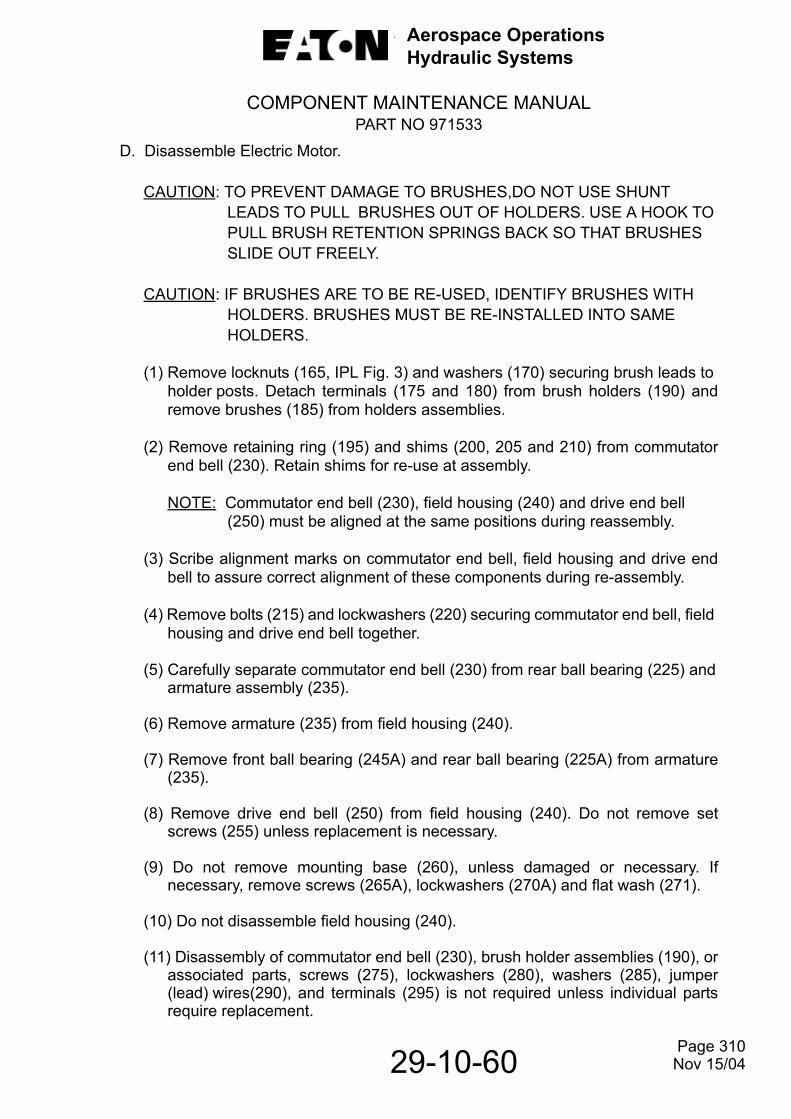
Aerospace OperationsHydraulic Systems
COMPONENT MAINTENANCE MANUALPART NO 971533
D. Disassemble Electric Motor.
CAUTION: TO PREVENT DAMAGE TO BRUSHES,DO NOT USE SHUNT LEADS TO PULL BRUSHES OUT OF HOLDERS. USE A HOOK TO PULL BRUSH RETENTION SPRINGS BACK SO THAT BRUSHES SLIDE OUT FREELY.
CAUTION: IF BRUSHES ARE TO BE RE-USED, IDENTIFY BRUSHES WITH HOLDERS. BRUSHES MUST BE RE-INSTALLED INTO SAME HOLDERS.
(1) Remove locknuts (165, IPL Fig. 3) and washers (170) securing brush leads to holder posts. Detach terminals (175 and 180) from brush holders (190) andremove brushes (185) from holders assemblies.
(2) Remove retaining ring (195) and shims (200, 205 and 210) from commutatorend bell (230). Retain shims for re-use at assembly.
NOTE: Commutator end bell (230), field housing (240) and drive end bell (250) must be aligned at the same positions during reassembly.
(3) Scribe alignment marks on commutator end bell, field housing and drive endbell to assure correct alignment of these components during re-assembly.
(4) Remove bolts (215) and lockwashers (220) securing commutator end bell, field housing and drive end bell together.
(5) Carefully separate commutator end bell (230) from rear ball bearing (225) andarmature assembly (235).
(6) Remove armature (235) from field housing (240).
(7) Remove front ball bearing (245A) and rear ball bearing (225A) from armature(235).
(8) Remove drive end bell (250) from field housing (240). Do not remove setscrews (255) unless replacement is necessary.
(9) Do not remove mounting base (260), unless damaged or necessary. Ifnecessary, remove screws (265A), lockwashers (270A) and flat wash (271).
(10) Do not disassemble field housing (240).
(11) Disassembly of commutator end bell (230), brush holder assemblies (190), orassociated parts, screws (275), lockwashers (280), washers (285), jumper(lead) wires(290), and terminals (295) is not required unless individual partsrequire replacement.
Page 310
29-10-60 Nov 15/04
Aerospace OperationsHydraulic Systems
COMPONENT MAINTENANCE MANUALPART NO 971533
(12) Do not remove name plate (300, IPL Fig. 3) or warning placard (305) unless replacement is necessary. Refer to REPAIR.
Page 311
29-10-60 Nov 15/04
Aerospace OperationsHydraulic Systems
COMPONENT MAINTENANCE MANUALPART NO 971533
29-10-60
THIS PAGE LEFT BLANK INTENTIONALLY
Page 312 Nov 15/04

Aerospace OperationsHydraulic Systems
COMPONENT MAINTENANCE MANUALPART NO 971533
29-10-60
CLEANING1. Cleaning of Hydraulic Pump.
A. The consumable materials listed in Table 401 are required during cleaning operations. Equivalent substitutes may be used.
Cleaning MaterialsTable 401
B. After lapping operations, thoroughly brush lapped surface of part with a bristlebrush in a soap and water solution. Follow this operation cleaning part in a sonicor ultrasonic cleaner.
WARNING: USE CLEANING SOLVENTS IN WELL VENTILATED AREA TOPREVENT INJURY. AVOID PROLONGED BREATHING OF FUMES.KEEP SOLVENTS AWAY FROM OPEN FLAME.
CAUTION: DO NOT APPLY SONIC OR ULTRASONIC CLEANING OPERATIONSTO PARTS THAT CONTAIN OR ARE COMPOSED OF NON-METALLIC MATERIAL.
CAUTION: DO NOT IMMERSE HYDRAULIC MOTORPUMP ASSEMBLY IN CLEANING FLUID. MAKE CERTAIN ALL PORTS ARE PLUGGEDDURING CLEANING OPERATION.
NOTE: Steel parts may require demagnetizing.
MATERIAL AVAILABILITY
Cleaner, Ultrasonic Commercially available
Containers, Parts, Sealable Commercially available
Solvent, Dry cleaning (P-D-680) Commercially available
Skykleen 1000 Solution, St. Louis, MO
Wipers, Cotton Commercially available
Fluid, Hydraulic (Alkyl Phosphate Ester) Commercially available
Page 401 Nov 15/08

Aerospace OperationsHydraulic Systems
COMPONENT MAINTENANCE MANUALPART NO 971533
C. Use Skykleen 1000 or equivalent in ultrasonic cleaning equipment to clean allmetal parts, except parts that contain or are composed of non-metallic material.Pay particular attention to fluid passages in valve plate housing and mountingflange to make certain they are clean and free from obstructions.
D. Wipe non-metallic parts with clean, lint-free toweling moistened with dry-cleaning solvent, Federal Specification P-D-680, Type ll.
2. Lubrication of Hydraulic Pump Parts.
Lubricate cleaned parts with clean alkyl phosphate ester hydraulic fluid and place in heat sealable polyethylene bags or other suitable contaminant free sealable containers if parts are not to be used immediately.
NOTE: A good practice is to reclean and oil parts just prior to assembly if they have been placed in storage after initial cleaning.
3. Cleaning of Electric Motor.
WARNING: USE CLEANING SOLVENTS IN WELL VENTILATED AREA TO PREVENT INJURY. AVOID PROLONGED BREATHING OF FUMES. KEEP SOLVENTS AWAY FROM OPEN FLAME.
A. All parts except the armature (255, IPL Fig. 3), field housing assembly (260), brushes (205), bearings (245 and 265), and filter assembly (40),may be cleanedby washing in cleaning solvent (Federal Specification P-D-680, Type l or Type ll).
B. After cleaning and rinsing in solvent, blow all parts dry with low-pressure filtered compressed air 5 to 10 psig (34 to 70 kPa).
C. Remove brush dust and all other foreign matter from the armature assembly (255) and field housing assembly (260) with low-pressure filtered compressed air 25 to 30 psig (172 to 207 kPa). Wipe both assemblies with a soft cloth moistenedin cleaning solvent. Use a soft-bristle brush to clean between the slots on the commutator, and hard to reach areas of the stator assembly.
D. After cleaning the stator and armature assembly (255), dry in an oven for approximately two hours at 225° F (107° C).
E. Clean brushes (205) with a dry clean cloth only. Do not use a solvent.
Page 402
29-10-60 Nov 15/08
Aerospace OperationsHydraulic Systems
COMPONENT MAINTENANCE MANUALPART NO 971533
29-10-60
THIS PAGE LEFT BLANK INTENTIONALLY
Page 403 Nov 15/04

Aerospace OperationsHydraulic Systems
COMPONENT MAINTENANCE MANUALPART NO 971533
CHECK1. General.
In most cases a visual parts check will disclose damage necessitating repair or replacement. However, because of very close tolerances that must be maintained between certain parts, the checks covered in Fig. 501 are supplemented by those outlined in Fits and Clearances Table, Fig. 801.
2. Special Tools.
See SPECIAL TOOLS, FIXTURES AND EQUIPMENT for a complete list of all special tools recommended for maintenance and a description of their function. However, tooling and test equipment, other than those specified, may be used providing they perform the required operation. Refer to the following table for special tools recommended for checks.
3. Detailed.
A. In addition to a visual check, a magnetic particle check of all steel parts shall be made in accordance with Specification ASTM E 1444. Use the wet continuous process, with either longitudinal or circular magnetization, and a current magnitude of 800 to 1200 amperes per inch of part. Any evidence of cracks that will destroy the soundness of the part is cause for rejection. Parts that have passed this check shall be passed through a demagnetizing field then cleaned as instructed in CLEANING.
NOTE: Small cracks or inclusions may be removed providing the metal removedwill not affect the integrity of the part.
B. All non-steel metal parts shall be fluorescent penetrant checked as instructed inSpecification ASTM E 1417. Any evidence of cracks that will destroy the soundness of the part is cause for parts rejection. After this, thoroughly clean part as instructed in CLEANING.
T-108684 Air Gage Master Ring
T-219352 Air Gage Master Ring
T-415408 Air Gage Spindle
T-441647 End Play Checking Tool
29-10-60 Page 501 Nov 15/04

Aerospace OperationsHydraulic Systems
COMPONENT MAINTENANCE MANUALPART NO 971533
NOTE: Small cracks or inclusions may be removed providing the metal removed will not affect the integrity of the part.
C. Use optical flats and monochromatic light when checking flatness of lapping operations called for in REPAIR.
NOTE: A typical flatness measurement which depicts flatness to three helium light bands is illustrated in Fig. 502.
CAUTION: BE SURE VALVING FACES OF VALVE BLOCK (60, IPL FIG. 2) ANDCYLINDER BLOCK (180) ARE AS FLAT AS POSSIBLE. REFER TOFIG. 501.
D. Use a standard electronic amplifier (Profilometer, or equivalent) to measure surface roughness. Make certain surfaces are thoroughly cleaned before checking and part so mounted that the instrument will not pick up extraneous vibrations which will furnish a false reading on the micro inch scale.
E. Use precision checking equipment (standard visual amplifiers) such as Sheffield Precisionaire Column and Sheffield Comparator as shown in Figs. 503 and 504 respectively when checking ID and OD of parts.
F. Use equipment as illustrated in Fig. 505 to check end play of piston and shoe subassemblies (225, IPL Fig. 2).
G. Use plating thickness tester (Magnegage, or equivalent) when measuring thickness of bronze plating on steel back parts.
H. Use spring load testers such as Link Testing Devices (or equivalent) when checking springs for their performance characteristics.
I. Use Nital etch process to detect localized tempering (metallurgical burn) of hardened steel valve block (60, IPL Fig. 2) and shoe bearing plate (230). Tempered area will appear darker than the unaffected portion of the part. Proceed as follows:
WARNING: NITRIC ACID BURNS. BE VERY CAREFUL WHEN MIXING THE FOLLOWING SOLUTION TO PREVENT PERSONAL INJURY. WASH IMMEDIATELY WITH WATER IF ACID COMES IN CONTACT WITH SKIN.
CAUTION: ACID ETCHING PRODUCES A SMALL DIMENSIONAL CHANGE IN PARTS. DO NOT ALLOW SOLUTION TO REMAIN ON SURFACE ANY LONGER THAN SPECIFIED. WASH WITH WATER TO NEUTRALIZE.
Page 502
29-10-60 Nov 15/04
Aerospace OperationsHydraulic Systems
COMPONENT MAINTENANCE MANUALPART NO 971533
(1) Prepare etching and neutralizing solutions as follows:
WARNING: IN MAKING UP ETCHING SOLUTION, ALWAYS ADD ACID TOALCOHOL. POUR ABOUT ONE HALF THE AMOUNT OF ALCOHOL NEEDED INTO A GRADUATE, ADD THE REQUIRED AMOUNT OF ACID BY POURING SLOWLY DOWN THE SIDE OF THE GRADUATE. STIR, AND THEN ADD ADDITIONAL ALCOHOL TO OBTAIN THE REQUIRED
DILUTION.
(a) Etching Solution
Mix 4 ml of nitric acid and 50 ml of alcohol (ethyl or methyl) in a graduate, stir, and add additional alcohol to bring volume to 100 ml. Mix thoroughly.Maintain solution temperature between 70° -80°F (21° -27°C).
(b) Neutralizing Solution
Mix 10% (by weight) of trisodium phosphate to water or other suitable neutralizer.
(2) Clean part as called for in CLEANING.
(3) Immerse or swab surface to be checked with etching solution. Allow part to beexposed to this solution for 15 to 20 seconds.
(4) Rinse in cold water to remove etching solution.
(5) Immerse part in neutralizing solution.
(6) Rinse in water to remove neutralizing solution.
(7) Rinse in alcohol to remove water.
(8) Dry with stream of clean, warm, dry air.
(9) Check part for softened (tempered) areas which will appear darker than the unaffected portion of the part.
Page 503
29-10-60 Nov 15/04
Aerospace OperationsHydraulic Systems
COMPONENT MAINTENANCE MANUALPART NO 971533
29-10-60
General Check RequirementsFigure 501 (Sheet 1 of 14)
PART CHECK METHOD REQUIREMENT
Shock Mount, Subassembly (25, IPL Fig. 1)
Stud (40) threads.
Visual. No stripped or crossed threads permitted. Repair to serviceability or replace.
Shock mount (45) core for damage.
Visual. Replace shock mount if damaged.
Coupling Shaft(5,IPL Fig. 2)
Packing groove.
Visual. No nicks or burrs permitted.
Cracks. Fluorescent penetrant. No cracks permitted Refer to paragraph 3B.
Splines for wear or dam-age.
Visual and measured over standard over stan-dard 0.0600 inch (1.524 mm) diameter pins
Replace coupling shaft if it cannot meet dimensions specified in Fig 801.
Adjusting Screw (35,IPL Fig. 2)
Check for damaged threads or packing groove
Visual. If damaged, replace part.
Check for damaged threads or packing groove.
Visual. Visual.
Compensator Spring (50,IPL Fig. 2)
Check spring for distortion tortion
Spring load tester Refer to paragraph 3H
Replace spring if it cannot pass test called for in Fig. 801.
Page 504 Nov 15/04

Aerospace OperationsHydraulic Systems
COMPONENT MAINTENANCE MANUALPART NO 971533
29-10-60
General Check RequirementsFigure 501 (Sheet 2)
PART CHECK METHOD REQUIREMENT
Valve Block and Spool Sub-assembly (60, IPL Fig. 2).
NOTE: This subassembly consists of spool (70) and valve block(60) which are matched at initial assembly to very close tol-erances. Do not intermix these parts with like parts of othersubassemblies.
Check for iswear on IDblock (60) andOD of spool(70).
Standard visual amplifier and surface finish analyzer. Refer to paragraphs 3D and 3E.
Replace subassembly ifclearance is greater thanthat specified in Fig. 801.ofvalve Surface shall notexceed 4 micro inch (0.1micron).
Check opera-tion of spool invalve block
Visual. There shall be no evidence of sticking or rough operation. If necessary, perform a light lapping operation using jeweler’s rouge. Do not destroy close tolerance fit specified in Fig. 801 Thoroughly clean parts after lapping.
ValveBlock andBearingSubassembly (75, IPL Fig. 2)
Cracks. Magnetic particle. Referto paragraph 3A
Replace valve block if itcannot pass this check.
Check for damaged locating pin hole and/or sealing groove.
Visual. Replace valve block if holeor groove is damaged.
Page 505 Nov 15/04

Aerospace OperationsHydraulic Systems
COMPONENT MAINTENANCE MANUALPART NO 971533
29-10-60
General Check RequirementsFigure 501 (Sheet 3)
PART CHECK METHOD REQUIREMENT
Valve Block and Bearing Subas-sembly (75, IPL-Fig. 2)
Check for wear and damage on valving surface that mates with cylinder.block (185Fig. 2)
Surface flatness testerand surface finish ana-lyzer. Refer to para-graphs 3C and 3D.
Surfaces shall be flat withinthree helium light bands andhave a surface finish notexceeding four micro inch(0.1 micron Lap face asinstructed in REPAIR. Afterlapping part shall meet dime sions specified in Fig.801.
Check for bronze smear-ing on mates with cylinder block (185).
Visual. Remove any evidence of bronze smearing by lapping as instructed in REPAIR. Nital etch surface as called for in CHECK paragraph 3I to assure that localized annealing has not occurred. If annealing has occurred, additional lapping will be required to remove discolored area. Replace part if it cannot meetrequirements specified in Fig.801.
MatingRing (110,IPL Fig. 2)
Cracks. Magnetic particle. Referto paragraph 3A.
Replace part if it fails thischeck.
Page 506 Nov 15/04

Aerospace OperationsHydraulic Systems
COMPONENT MAINTENANCE MANUALPART NO 971533
29-10-60
General Check RequirementsFigure 501 (Sheet 4)
PART CHECK METHOD REQUIREMENT
MatingRing(110,IPLFig.2)(Cont’d)
Check for wear or dam-age on sealing face that mates with seal element (125)
Surface flatness tester and surface finish ana-lyzer. Refer to para-graphs 3C and 3D.
Surface shall be flat withinfour helium light bands andhave a surface finish notexceeding four micro inch(0.1 micron) If necessary,lap part as instructed inREPAIR. After lapping, partshall meet dimensionsspecified in Fig. 801.
Shaft SealSubas-sembly(120,IPLFig. 2)
Check for proper height of assembled subassembly under load.
Spring load tester. Referto paragraph 3H.
Replace or grind spacer(300) to obtain dimensionspecified in Fig. 801. Referto ASSEMBLY, paragraph4F
Seal Ele-ment (125,IPL Fig. 2)
Cracks. Fluorescent penetrant.Refer to paragraph 3B.
Replace part if it cannotpass this check.
WaveSpring(145, IPLFig. 2)
Check wavespring forfatigue
Spring load tester. Ref toparagraph 3H.
Replace part if it cannotmeet requirements specifiedin Fig801
Housingand InsertsSubas-sembly(155,IPLFig. 2)
Cracks. Fluorescent pene-trant.Refer to paragraph3B
Cracks that destroysoundness of part willrequire replace unless it canbe repaired as called for inREPAIR.
Page 507 Nov 15/04

Aerospace OperationsHydraulic Systems
COMPONENT MAINTENANCE MANUALPART NO 971533
29-10-60
General Check RequirementsFigure 501 (Sheet 5)
PART CHECK METHOD REQUIREMENT
Housingand InsertsSubas-sembly(155 IPL-Fig.2)(cont’d)
Check for piston (175) wear in bore ID for actuator.
Surface finish analyzer and standard visual amplifier.
Bore shall be free of abra-sions and have a surfacefinish of 32 micro inch (0.8micron).Replace housing ifID dimensions specified inFig. 801 cannot be met
ActuatorPiston(175,IPLFig. 2)
Check piston for wear and scoring.
Surface finish analyzer and standard visual amplifier. Refer to paragraphs 3D and 3E.
Surface finish shall notexceed eight micro inch (0.2micron).Replace part if itcannot meet dimensionsspecified in Fig. 801
CylinderBlock(180IPLFig. 2)
Cracks. Fluorescent penetrantRefer to paragraph 3B.
Replace part if it fails topass this check.
Check piston bore ID for wear.
Use air gage spindle T-415408 and air gagerings T-108684 andT-219352. See Fig. 503and refer to paragraph3E.
Replace cylinder block ifpiston bores cannot meetdimensions specified in Fig.801.
Check for we ar or dam-age on valvingface that mates with valve block(60)
Surface flatness testerand surface finish ana-lyzer. Refer to para-graphs 3C and 3E
Surface shall be flat withinfour helium light bands andhave a surface finish notexceeding 4 micro inch (0.1micron). Lap face asinstructed in REPAIR para-graph 8A. After lapping partshall meet dimensionsspecified in Fig. 801
Page 508 Nov 15/04

Aerospace OperationsHydraulic Systems
COMPONENT MAINTENANCE MANUALPART NO 971533
29-10-60
General Check RequirementsFigure 501 (Sheet 6)
PART CHECK METHOD REQUIREMENT
CylinderBlock (180,IPL Fig. 2)(cont’d)
Check for wear on internal splines.
Use standard 0.0540 inch (1.372 mm)diameter pin gages and standard gage blocks.
Replace cylinder block if notwithin limits specified in Fig 801.
Spring(195,IPLFig. 2)
Check spring for distortion and fatigue.
Spring load tester. Referto paragraph 3H.
Replace spring if it cannotmeet limits specified in Fig. 80l.
RetainerPlate(215,IPLFig. 2)
Cracks. Fluorescentpenetrant.Refer toparagraph 3B.
Replace part if it fails topass this check.
Check for wear or dam-age on bronze face
Surface flatness testerand surface finish ana-lyzer. Refer to para-graphs 3C and 3E
Surface shall be flat within0.001 inch (0.03 mm) andhave surface finish notexceeding 16 micro inches(0.4 micron). Lap face asinstructed in REPAIR Afterlapping, part shall meetdimensions specified in Fig. 801
Bronze platethickness.
Plating thickness testerRefer to paragraph 3G
Plate thickness shall not beless than 0.005 inch (0.13 mm).
PistonShoeRetainingPlate(220,IPLFig. 2)
Cracks. Magnetic particle. Referto paragraph 3A
Replace part if it cannotpass this check.
Page 509Nov 15/04
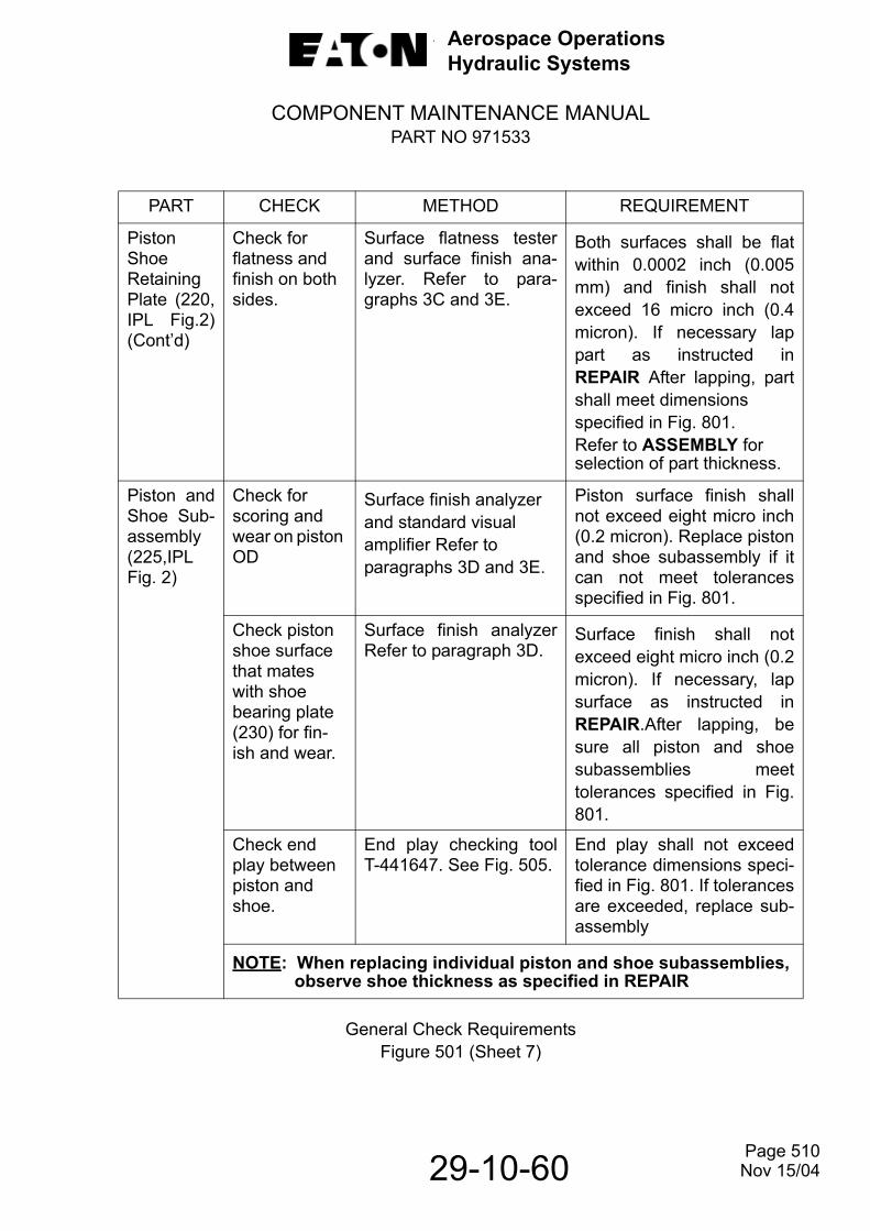
Aerospace OperationsHydraulic Systems
COMPONENT MAINTENANCE MANUALPART NO 971533
29-10-60
General Check RequirementsFigure 501 (Sheet 7)
PART CHECK METHOD REQUIREMENT
PistonShoeRetainingPlate (220,IPL Fig.2)(Cont’d)
Check for flatness and finish on both sides.
Surface flatness testerand surface finish ana-lyzer. Refer to para-graphs 3C and 3E.
Both surfaces shall be flatwithin 0.0002 inch (0.005mm) and finish shall notexceed 16 micro inch (0.4micron). If necessary lappart as instructed inREPAIR After lapping, partshall meet dimensionsspecified in Fig. 801.Refer to ASSEMBLY forselection of part thickness.
Piston andShoe Sub-assembly(225,IPLFig. 2)
Check for scoring and wear on piston OD
Surface finish analyzer and standard visual amplifier Refer to paragraphs 3D and 3E.
Piston surface finish shallnot exceed eight micro inch(0.2 micron). Replace pistonand shoe subassembly if itcan not meet tolerancesspecified in Fig. 801.
Check piston shoe surface that mates with shoe bearing plate (230) for fin-ish and wear.
Surface finish analyzerRefer to paragraph 3D.
Surface finish shall notexceed eight micro inch (0.2micron). If necessary, lapsurface as instructed inREPAIR.After lapping, besure all piston and shoesubassemblies meettolerances specified in Fig.801.
Check end play between piston and shoe.
End play checking toolT-441647. See Fig. 505.
End play shall not exceedtolerance dimensions speci-fied in Fig. 801. If tolerancesare exceeded, replace sub-assembly
NOTE: When replacing individual piston and shoe subassemblies, observe shoe thickness as specified in REPAIR
Page 510 Nov 15/04

Aerospace OperationsHydraulic Systems
COMPONENT MAINTENANCE MANUALPART NO 971533
29-10-60
General Check RequirementsFigure 501 (Sheet 8)
PART CHECK METHOD REQUIREMENT
ShoeBearingPlate(230,IPLFig. 2)
Cracks. Magnetic particle. Refer Replace part if it cannot meet this check to paragraph 3A.
Check for flatness and wear on face that mates with piston and shoe subassem-blies.
Surface finish analyzer.Refer to paragraph 3D.
Surface shall be flat within four helium light bands, parallel with back side within 0.0002 inch (0.005mm) and have a surface finish not exceeding four micro inch (0.1 micron). If necessary, lap part as instructed in REPAIR. After lapping, part shall meet dimensions specified in Fig. 801.
Yoke, Ball and Pin Subas-sembly (240,IPL Fig. 2)
Cracks Magnetic particle. Referto paragraph 3A.
Replace part if it cannotpass this check.
Check wear and surface finish on trun-nions for pintle bearings (235)
Surface finish analyzerand standard visualamplifier.Refer to para-graphs 3D and 3E
OD of trunnions shall meettolerance dimensions speci-fied in Fig. 801. Surface fin-ish shall not exceed 32micro inch (0.8 micron) asspecified in 801.Fig. 801.
Check security of ball that mates with spring guide (255).
Visual. Ball shall be secure in yoke.
Page 511 Nov 15/04
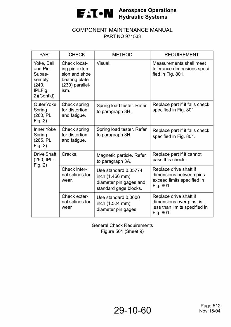
Aerospace OperationsHydraulic Systems
COMPONENT MAINTENANCE MANUALPART NO 971533
29-10-60
General Check RequirementsFigure 501 (Sheet 9)
PART CHECK METHOD REQUIREMENT
Yoke, Ball and Pin Subas-sembly (240, IPLFig. 2)(Cont’d)
Check locat-ing pin exten-sion and shoe bearing plate (230) parallel-ism.
Visual. Measurements shall meet tolerance dimensions speci-fied in Fig. 801.
Outer Yoke Spring (260,IPL Fig. 2)
Check spring for distortion and fatigue.
Spring load tester. Refer to paragraph 3H.
Replace part if it fails check specified in Fig. 801
Inner Yoke Spring (265,IPL Fig. 2)
Check spring for distortion and fatigue.
Spring load tester. Refer to paragraph 3H
Replace part if it fails check specified in Fig. 801.
Drive Shaft (290, IPL-Fig. 2)
Cracks. Magnetic particle. Refer to paragraph 3A.
Replace part if it cannot pass this check.
Check inter-nal splines for wear.
Use standard 0.05774 inch (1.466 mm) diameter pin gages and standard gage blocks.
Replace drive shaft if dimensions between pins exceed limits specified in Fig. 801.
Check exter-nal splines for wear
Use standard 0.0600 inch (1.524 mm) diameter pin gages
Replace drive shaft if dimensions over pins, is less than limits specified in Fig. 801.
Page 512Nov 15/04
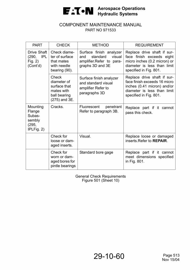
Aerospace OperationsHydraulic Systems
COMPONENT MAINTENANCE MANUALPART NO 971533
29-10-60
General Check RequirementsFigure 501 (Sheet 10)
PART CHECK METHOD REQUIREMENT
Drive Shaft(290, IPLFig. 2) (Cont’d)
Check diame-ter of surface that mates with needle bearing (90).
Surface finish analyzerand standard visualamplifier.Refer to para-graphs 3D and 3E
Replace drive shaft if sur-face finish exceeds eightmicro inches (0.2 micron) ordiameter is less than limitspecified in Fig. 801.
Checkdiameter of surface that mates with ball bearing (275) and 3E.
Surface finish analyzer and standard visual amplifier Refer to paragraphs 3D
Replace drive shaft if sur-face finish exceeds 16 microinches (0.41 micron) and/ordiameter is less than limitspecified in Fig. 801.
MountingFlangeSubas-sembly(295, IPLFig. 2)
Cracks. Fluorescent penetrantRefer to paragraph 3B.
Replace part if it cannotpass this check.
Check for loose or dam-aged inserts.
Visual. Replace loose or damagedinserts.Refer to REPAIR.
Check for worn or dam-aged bores for pintle bearings
Standard bore gage Replace part if it cannotmeet dimensions specifiedin Fig. 801.
Page 513 Nov 15/04

Aerospace OperationsHydraulic Systems
COMPONENT MAINTENANCE MANUALPART NO 971533
29-10-60
General Check RequirementsFigure 501 (Sheet 11)
PART CHECK METHOD REQUIREMENT
MountingFlange Subassembly(295,IPLFig.2)(Cont’d)
Check sur-face finish of mating ring (110) bore.
Surface finish ana-lyzer.Refer to paragraph3D
Replace part if it cannotmeet dimensions specifiedin Fig.801
Check for damage in seal groove area.
Visual. Replace part if damage can-not be repaired withoutaffecting sealing ability.
RFI Filter (40,IPL Fig. 3)
Check for damaged case, connector orterminals
Visual. Replace filter if defective.
CAUTION: DO NOT HI-POT FILTER, INTERNAL RFI FILTER CAPACITORS WILL BE DAMAGED
Thermostat(75, IPLFig. 3)
Check for physical damage and continuity.
Visual and ohmmeter. Replace thermostat if defec-tive Thermostat is normallyclosed
Shroud (120,IPL Fig. 3)
Check for dents, cracks or brokenwelds
Visual. Replace shroud if defective
Cover (135, IPLFig 3)
Check for dents, cracks or broken welds.
Visual. Replace cover if defective.
Page 514 Nov 15/04

Aerospace OperationsHydraulic Systems
COMPONENT MAINTENANCE MANUALPART NO 971533
29-10-60
General Check RequirementsFigure 501 (Sheet 12)
PART CHECK METHOD REQUIREMENT
Fan (160,IPL Fig. 3)
Check for chipped, cracked or broken blades.
Visual and fluorescent penetrant. Refer to para graph 3B.
Replace fan if defective.
Brush Holders (190, IPL Fig. 3)
Check for cracks or dis-coloration
Visual. Replace part if cracked or discolored
Brush guides for damage.
Visual. Replace part if damage is noted
Spring ten-sion.
Spring scale. Replace spring if spring ten-sion is not within 28 to 35 ounces (794 to 992 gm).
NOTE: To check springs, connect a scale to spring and pull straight out until contact point of spring is in line with top of brush guide
Commutator End Bell (230, IPL Fig. 3)
Check for cracks or other damage
Visual. Replace end bell if defective.
Check bore ID of bear ing (225A) for wear
Micrometer. Replace part if bore exceeds limits specified in Fig. 801
Armature (235, IPL Fig. 3)
Check for worn, pitted or burned com-mutator bars
Visual. Replace part if it cannot be repaired as outlined in REPAIR paragraph 10. Must meet requirements specified in Fig. 801 after repair.
Page 515 Nov 15/04
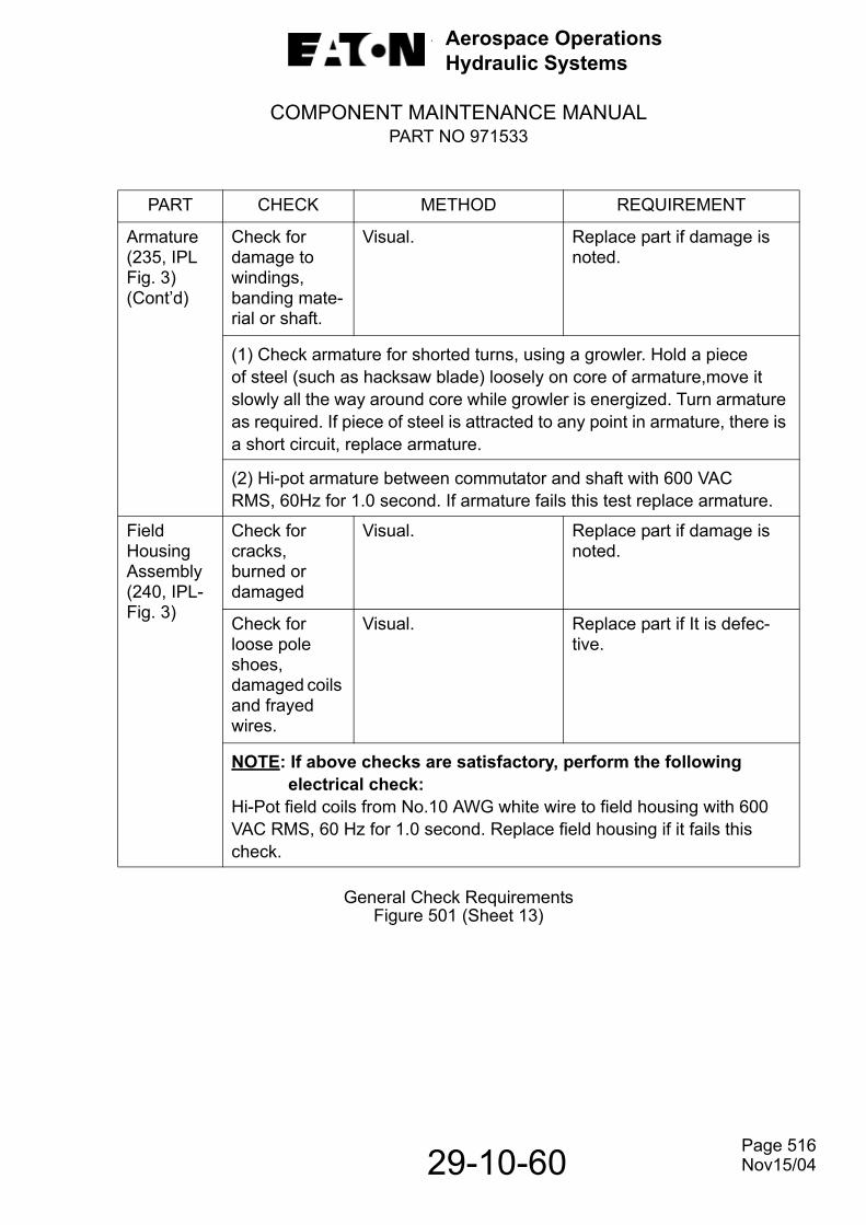
Aerospace OperationsHydraulic Systems
COMPONENT MAINTENANCE MANUALPART NO 971533
29-10-60
General Check RequirementsFigure 501 (Sheet 13)
PART CHECK METHOD REQUIREMENT
Armature (235, IPL Fig. 3) (Cont’d)
Check for damage to windings, banding mate-rial or shaft.
Visual. Replace part if damage is noted.
(1) Check armature for shorted turns, using a growler. Hold a pieceof steel (such as hacksaw blade) loosely on core of armature,move it slowly all the way around core while growler is energized. Turn armature as required. If piece of steel is attracted to any point in armature, there is a short circuit, replace armature.
(2) Hi-pot armature between commutator and shaft with 600 VACRMS, 60Hz for 1.0 second. If armature fails this test replace armature.
Field Housing Assembly (240, IPL-Fig. 3)
Check for cracks, burned or damaged
Visual. Replace part if damage is noted.
Check for loose pole shoes, damaged coils and frayed wires.
Visual. Replace part if It is defec-tive.
NOTE: If above checks are satisfactory, perform the following electrical check:
Hi-Pot field coils from No.10 AWG white wire to field housing with 600 VAC RMS, 60 Hz for 1.0 second. Replace field housing if it fails this check.
Page 516 Nov15/04

Aerospace OperationsHydraulic Systems
COMPONENT MAINTENANCE MANUALPART NO 971533
29-10-60
General Check RequirementsFigure 501 (Sheet 14)
Measurement of Light BandsFigure 502
PART CHECK METHOD REQUIREMENT
Drive End Bell (250, IPL Fig. 3)
Check for cracks or other damaged.
Visual. Replace end bell if defective,except studs which may be replaced indi-vidually if dam aged.
Check bore ID for bearing (245A) for wear.
Micrometer. Replace end bell if bore exceeds limits specified in Fig. 801.
Page 517Nov 15/04

Aerospace OperationsHydraulic Systems
COMPONENT MAINTENANCE MANUALPART NO 971533
29-10-60
Measuring Cylinder Block BoresFigure 503
Measuring Piston SizeFigure 504
Page 518 Nov 15/04

Aerospace OperationsHydraulic Systems
COMPONENT MAINTENANCE MANUALPART NO 971533
29-10-60
Measuring Piston and Shoe End PlayFigure 505
Page 519 Nov 15/04

Aerospace OperationsHydraulic Systems
COMPONENT MAINTENANCE MANUALPART NO 971533
29-10-60
THIS PAGE LEFT BLANK INTENTIONALLY
Page 520 Nov 15/04

Aerospace OperationsHydraulic Systems
COMPONENT MAINTENANCE MANUALPART NO 971533
REPAIR1. General.
A. The consumable materials listed in tabular form in Table 601 are required during repair operations called for in this manual. Equivalent substitutes may be used.
Repair MaterialTable 601
MATERIAL TYPE ORGRADE AVAILABILITY
Polishing Paper 9 micron Commercially availableAlodine (MIL-A-8625) Commercially available
Lapping powder(Aluminum oxide) 12.5 micron grit Commercially available
Onion Skin Paper 25% CottonFiber Commercially available
Lapmaster powder 1800 Lapmaster International-Inc.Morton Grove, Illinois
Lubricant MIL-L-17672 Commercially available
Loctite A
Loctite Aerospace2850 Willow Pass Road
P. O. Box 312, Bay Point, CA 94565-0031
Epoxy resin Magna-Tac M-611 Beacon Chemical Co.Mt. Vernon, N.J.
Curing Agent CH-16 Beacon Chemical Co.Mt. Vernon, N.J.
Solvent, Dry cleaning P-D-680 Commercially available
Lapping Plate Diamond Matrix(3000 Mesh)
Ablap Corp.,Franklin, PA
Diamond Lapping Compound USBS #6 Abrasive Diamond Tool Co.Madison Heights, M
EPO DynaweightBalancing Compound Commercially available
Page 601
29-10-60 Nov 15/08
Aerospace OperationsHydraulic Systems
COMPONENT MAINTENANCE MANUALPART NO 971533
B. Parts which fail to meet requirements as specified in CHECK shall be repaired or replaced. Damaged or worn parts which cannot be restored to serviceabilityfollowing the instructions in this section, shall be replaced.
C. Parts which have been repaired must conform to dimensional requirements of Table 801 after repair.
2. Special Tools.
Tooling and test equipment other than those herein specified may be used provided they perform the required operations. Table 602 is a list of special tools, fixtures and equipment used during repair.
List of Special Tools, Fixtures and EquipmentTable 602
NOTE: Always use the proper tool for the job. Be sure wrenches fit properly on nuts or bolt heads. Do not use pliers to remove nuts or bolts. Do not usescrewdrivers to separate mating parts. Use a soft faced rod or mallet fortapping around binding areas.
3. Use of Polishing Paper.
CAUTION: WHEN POLISHING PAPER IS USED, DO NOT POLISH NON-STEEL METAL PARTS ON PAPER THAT HAS BEEN USED FOR STEEL BECAUSE STEEL PARTICLES RETAINED IN THE PAPER WILL DAMAGE A NON-STEEL SURFACE.
Dress down minor scratches or burrs on operating parts with polishing paper9micron, or equivalent, or Arkansas stone.
4. Welding.
CAUTION: THIS PROCESS MAY CAUSE SIGNIFICANT DISTORTION TO CASTINGS.
A. Repair of aluminum alloy castings may be made by aluminum welding per Specification SAE AMS-STD-2219 and finishing to size.
T-443826 Gang Lap FixtureThree Cornered Scrapper
8DL-3000 Mesh Ablap Lapping PlateLapping Machine
5-005-2-0015 Ceramic Polishing PlateArkansas Stone
Page 602
29-10-60 Nov 15/04
Aerospace OperationsHydraulic Systems
COMPONENT MAINTENANCE MANUALPART NO 971533
29-10-60
B. Check all machined surfaces before and after welding for possible distortion caused by the welding operation.
C. Refer to CHECK, paragraph 3B for fluorescent penetrant procedures to follow after a welding operation has been performed.
D. Refer to paragraph 5 for protective finishing of exposed metal surfaces.
5. Protective Finish.
WARNING: TO AVOID INJURY, OPERATORS SHOULD WEAR PROTECTIVE CLOTHING TO AVOID CONTACT WITH ALODINE SOLUTION.
A. Refinish aluminum surfaces that have had their protective coatings removed by applying alodine solution.
B. Proceed as follows:
(1) Clean repaired area with cleaning solvent. (Ref. CLEANING).
(2) Rinse thoroughly with water to remove solvent.
WARNING: EQUIPMENT USED TOAPPLY ALODINE SOLUTION SHOULD NOT BE ALLOWED TO DRY OUT. IF ALLOWED TO DRY, THEYMAY CONSTITUTE A FIRE HAZARD.
(3) Apply alodine solution with brush, sponge or rag.
(4) Allow solution to remain on surface from one to five minutes to allow color to match adjacent areas.
(5) Remove excess solution by flushing with clean water.
(6) Allow a minimum of one hour to dry before handling repaired surface.
6. Repair of Inserts.
A. Do not remove inserts unless loose or damaged. If removal is necessary, a standard Helicoil kit provides the necessary means for insert removal. If such a kit is not available, inserts may be removed as follows:
(1) Insert proper sized, three-cornered scraper into insert.
(2) After getting a good solid fit, turn insert out of housing.
(3) Air blow bore.
Page 603 Nov 15/04

Aerospace OperationsHydraulic Systems
COMPONENT MAINTENANCE MANUALPART NO 971533
29-10-60
7. Lap Steel Parts as Follows:
A. Mating Ring (110, IPL Fig. 1)
(1) If surface is badly scored or worn and sufficient surface stock is available, lightly grind it before lapping.
(2) If part is to be lapped by hand, use a grooved lapping plate. If it is to be lapped on a lapping machine, use a lapping plate without grooves.
(3) The lapping compound consists of one (1) U.S. pound of 12.5 micron grit aluminum oxide, Lapmaster powder #1800 (product #0006), Lapmaster International-Inc. or equivalent and one (1) gallon of lubricant (MIL-L-17672).
(4) Apply a small amount of compound to surface, and using a circular motion, lap it in such a manner that the whole working face of lapping plate is used.
CAUTION: EXCESSIVE POLISHING WILL ERODE OUTER EDGES OF PART AND MAY DESTROY HYDRAULIC BALANCE BY REDUCING EFFECTIVE SEALING AREA.
NOTE: When lapping parts on a lapping plate and using lapping compound,the lapped surface will become impregnated with the compound. After lapping, thoroughly brush lapped surface using a soft bristle brush ina soap and water solution. Rinse off soap solution and dry part. Follow this operation by cleaning part in a sonic or ultrasonic cleaner.
(5) Clean and finish polish the part on 9 micron polishing paper tightly drawn over a surface plate.
(6) After polishing, thoroughly clean part as instructed in CLEANING and check flatness and surface finish of lapping operations as instructed in CHECK.After this, check edges of lands or other openings in lapped face for possibleburrs or feather edges raised by lapping operation. Remove these burrs butleave edge square. Clean again after this operation.
8. Lap Non-Steel Parts as Follows:
A. Shaft Seal Element (125, IPL Fig. 2).
NOTE: Lapping of non-steel parts on a lapping machine with lapping compound,the same as for steel parts as specified in paragraphs 7C and 7D, isacceptable. However, special attention shall be given to cleaning the partafter lapping operation.
(1) If needed, lap part on a lapping machine as called for in paragraphs 7C and 7D,except limit time on the machine to four or five cycles. Clean part perCLEANING section.
Page 604 Nov 15/08

Aerospace OperationsHydraulic Systems
COMPONENT MAINTENANCE MANUALPART NO 971533
29-10-60
(2) Touch lap sealing element on a diamond matrix (Ablap) polishing plate (3000 mesh) to restore flatness and remove the residual aluminum oxide
contamination.
(3) Finish polish part on a flat, clean ceramic polishing plate or 9 micron polishingpaper. Use a circular motion and change hand hold on part every few circles.Use a ceramic polishing plate manufactured by Lapmaster International,Morton Grove, Illinois, their number 5-005-2-0015 (or equivalent).
CAUTION: DO NOT POLISH THE PART ON A STONE OR PAPER THATHAS BEEN USED FOR METAL PARTS. THE METAL PARTICLESRETAINED IN SUCH A STONE OR PAPER WILL DAMAGE THEPART.
(4) After polishing part, clean it as instructed in CLEANING. Check for possible burrs or feather edges raised by the lapping and polishing operation. Remove these burrs. Check accuracy of lapping operation as instructed in CHECK. Clean part again after this operation.
B. Cylinder Block (180, IPL Fig. 2) and Retainer Plate (210).
(1) If needed, lap part on a lapping plate as called for in paragraphs 7C and 7D.
NOTE: Lapping of non-steel parts on a lapping machine with lappingcompound, the same as for steel parts as specified in paragraph 7 isacceptable.However, special attention shall be given to cleaning thepart after lapping operation.
(2) Thoroughly clean the part as instructed in CLEANING.
CAUTION: DO NOT POLISH NON-STEEL METAL PARTS ON PAPER THAT HAS BEEN USED FOR STEEL. STEEL PARTICLES RETAINED IN THE PAPER WILL DAMAGE A NON-STEELSURFACE. IN ADDITION, EXCESSIVE POLISHING WILL ERODE THE OUTER EDGES OF THE PART AND MAY DESTROY HYDRAULIC BALANCE BY REDUCING THE EFFECTIVE SEALING AREA.
(3) Finish polish parts on 9 micron polishing paper, tightly drawn over a surfaceplate.
(4) Measure thickness of bronze plating on retainer plate (180) as called for in CHECK. Plating thickness shall not be less than 0.005 inch (0.13 mm).
(5) Check surface flatness and finish as called for in CHECK. Surface must conform to requirements specified in Figs. 501 and 801.
Page 605 Nov 15/04

Aerospace OperationsHydraulic Systems
COMPONENT MAINTENANCE MANUALPART NO 971533
29-10-60
C. Shoes of Piston and Shoe Subassemblies (225, IPL Fig. 2).
CAUTION: GANG LAP FIXTURE T-443826 MUST BE USED WITH ITS GUIDERING TO ENSURE THAT PARALLELISM OF SHOE FACE ISMAINTAINED.
(1) Use gang lap fixture T-443826 as shown in Fig. 601 and a lapping plate. Refer to paragraph 7C and 7D for lapping.
NOTE: All nine piston shoes must be lapped as a set to maintain theirtolerancethickness (that area between shoe retainer plate (220, IPLFig.2) and shoe bearing plate (230) of 0.0004 inch (0.010 mm) ofeach other.
(2) After this operation, thoroughly clean part as instructed in CLEANING.
(3) Finish polish part on 9micron polishing paper, tightly drawn over a surface plate.Again, clean the part.
Gang Lap of Piston ShoesFigure 601
Page 606 Nov 15/04

Aerospace OperationsHydraulic Systems
COMPONENT MAINTENANCE MANUALPART NO 971533
29-10-60
9. Replace Bonded Plates.
A. If identification plate (55, IPL Fig. 1) or modification plate (60), rotation plate (315, IPL Fig. 2), instruction plate (320) or name plate (300, IPL Fig. 3) requires replacement, proceed as follows:
B. If plates must be removed, place housing (not a complete motorpump assembly)in an electric oven preheated to 280° - 300° F (138 ° - 149° C) or maximum of 225° F (107°C) for field housing (260, IPL Fig. 3) and heat part for a sufficient length oftime to loosen the epoxy bond. Peel off plate.
NOTE: Retain removed identification plate (55, IPL Fig. 1) so that data information can be transferred to new plate.
C. After part has cooled, thoroughly clean area to receive new plate to remove residue bonding epoxy resin. If necessary, form plates to contoured surface priorto bonding.
D. Use epoxy resin (Magna-Tac, M-611) and curing agent (CH-16), manufactured by Beacon Chemical Company, Mt. Vernon, NY 10550 (or equivalent) to bondnew plates as follows:
(1) Surfaces which have been painted (except those painted with epoxy paints)must be completely stripped. Thoroughly clean the surface to which plate is tobe secured using a lint-free toweling moistened with dry-cleaning solvent (P-D-680 or equivalent). Refer to any additional information supplied by the adhesive manufacturer to ensure a good bond.
(2) Combine 100 parts by weight of epoxy resin with 32 parts by weight of CuringAgent CH-16 and thoroughly mix.
(3) The components shall be weighed to an accuracy of ± 5 percent.
(4) Apply adhesive to each of the surfaces to be bonded using a sufficient amount to fill the space between the parts after assembly.
(5) Bring faying surfaces together and apply only sufficient pressure to cause adhesive to squeeze out around edges of plate. Maintain pressure until the adhesive is cured.
(6) Remove excessive adhesive before curing by using a lint-free towel moistened with toluene, acetone, ketone, or equivalent solvent.
(7) Cure adhesive-bonded joint at 150° F (65.5° C) for 60 minutes or allow to cure overnight at room temperature.
(8) Exposed joints shall show a complete fillet line or ring of adhesive betweencomponent parts.
Page 607Nov 15/04

Aerospace OperationsHydraulic Systems
COMPONENT MAINTENANCE MANUALPART NO 971533
29-10-60
10. Repair of Armature.
A. Rough-Cut Commutator.
(1) If inspection reveals that the commutator is rough, pitted, scored, or burned,refinish in a lathe that is accurately setup and adjusted. It is preferable to use alathe that supports the armature on its bearing journals to ensure properconcentricity. Concentricity is extremely important for proper operation and life.
(2) Remove only the material necessary to clean and true-up the commutatorsurface. Use a carbide tool to remove all grooves, pits, and other surfacedamage.After finishing the rough cut, check the commutator diameter to besure it is not less than the minimum diameter of 1.900 inches (48.26 mm). Ifthe commutator diameter is less than 1.900 inches (48.26 mm), it should bereplaced.
B. Undercutting Mica.
Once the commutator has been rough cut, and is still larger than the minimum allowable diameter of 1.900 inches (48.26 mm), the mica should be undercut to adepth of 0.035/0.030 X 0.030 inch (0.89/0.76 X 0.76 mm) wide, following theoriginal undercutting slots.
C. Final Cut Commutator.
The final cut is made with a diamond head cutting tool. The cutting point of thetool must be on the exact centerline of the commutator to a maximum of 0.002inch (0.05 mm) below centerline (never above centerline). Use a light airflow tokeep the chips off the commutator while it is being cut. Check concentricities andminimum allowable commutator diameter. Do not touch or otherwise contaminatethe commutator after the final cut has been made. Cover with a clean oil-freepaper until ready to reassemble.
D. Balancing.
After the commutator has been refinished, check the armature for proper balance,which should be within five-grain inches at each end. If balancing is required, addEPO Dynaweight Balancing Compound as required.
11. Repair of Field Housing.
Other than repairing minor damage to insulation or tightening loose terminations, the field housing assembly must be replaced if defective.
Page 608 Nov 15/04
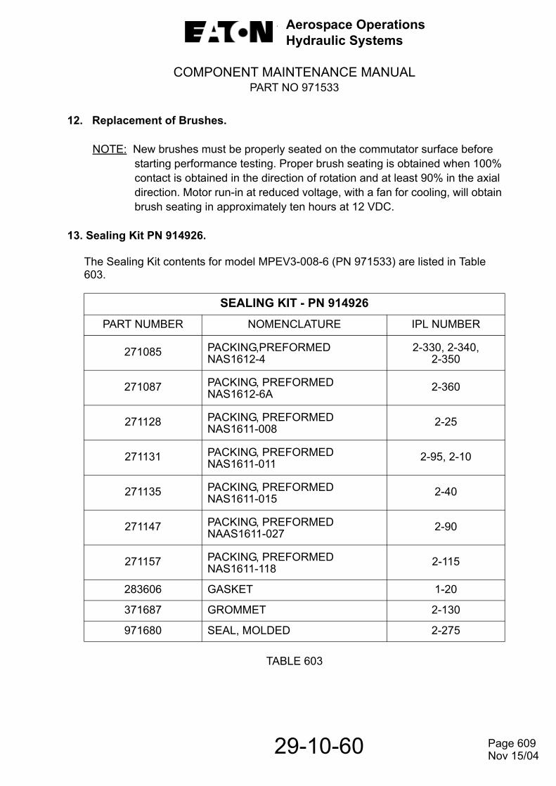
Aerospace OperationsHydraulic Systems
COMPONENT MAINTENANCE MANUALPART NO 971533
12. Replacement of Brushes.
NOTE: New brushes must be properly seated on the commutator surface before starting performance testing. Proper brush seating is obtained when 100% contact is obtained in the direction of rotation and at least 90% in the axial direction. Motor run-in at reduced voltage, with a fan for cooling, will obtain brush seating in approximately ten hours at 12 VDC.
13. Sealing Kit PN 914926.
The Sealing Kit contents for model MPEV3-008-6 (PN 971533) are listed in Table 603.
TABLE 603
SEALING KIT - PN 914926PART NUMBER NOMENCLATURE IPL NUMBER
271085 PACKING,PREFORMEDNAS1612-4
2-330, 2-340,2-350
271087 PACKING, PREFORMEDNAS1612-6A 2-360
271128 PACKING, PREFORMEDNAS1611-008 2-25
271131 PACKING, PREFORMEDNAS1611-011 2-95, 2-10
271135 PACKING, PREFORMEDNAS1611-015 2-40
271147 PACKING, PREFORMEDNAAS1611-027 2-90
271157 PACKING, PREFORMEDNAS1611-118 2-115
283606 GASKET 1-20
371687 GROMMET 2-130
971680 SEAL, MOLDED 2-275
29-10-60 Page 609Nov 15/04

Aerospace OperationsHydraulic Systems
COMPONENT MAINTENANCE MANUALPART NO 971533
14. Overhaul Kit PN 914927.
The Overhaul Kit contents for model MPEV3-008-6 (PN 971533) are listed in Table 604.
TABLE 604
15. Corrosion Reduction- Filter Box
OVERHAUL KIT - PN 914927PART NUMBER NOMENCLATURE IPL NUMBER
211753 BEARING, BALL 2-285
297009 BEARING, ROLLER 2-235
332539 BEARING, ROLLER-NEEDLE 2-80
332956 WASHER, WAVE 2-145
342047 SPRING, HELICAL 2-135
342245 SPRING, HELICAL 2-50
571537 SPRING, HELICAL 2-265
571538 SPRING, HELICAL 2-260
622342 SPRING, HELICAL 2-195
211753 BEARING, BALL 2-285
Page 610
29-10-60 Nov 15/08
Aerospace OperationsHydraulic Systems
COMPONENT MAINTENANCE MANUALPART NO 971533
29-10-60
THIS PAGE LEFT BLANK INTENTIONALLY
Page 611 Nov 15/04

Aerospace OperationsHydraulic Systems
COMPONENT MAINTENANCE MANUALPART NO 971533
29-10-60
ASSEMBLY1. General.
A. The consumable materials listed in Table 701 are required during assembly operations.Equivalent substitutes may be used.
Assembly Materials Table 701
B. Use all new packings, backup rings, gaskets and bearings (if bearings were removed from their mountings). Lubricate packings and backup rings with hydraulic fluid before installation.
C. Clean and lubricate all hydraulic pump parts in clean alkyl phosphate ester base hydraulic fluid just prior to assembly to provide initial pump lubrication. Also, in the case of screws, to assure more accurate torque readings. Refer to Table 801 for applicable torque values.
D. The assembly area should be void of materials and equipment not directly associated with the assembly of these units. Normal room temperature and humidity conditions should prevail. Ventilation should be such that outside small particle debris is not allowed to settle in the area. The area should be isolated or removed from particle generating equipment such as grinders, lapping machines paint spray booths, sand blasting machines, etc. Good house keeping practices that assure minimum contamination should be maintained at all times.
MATERIAL AVAILABILITYFluid, Hydraulic, Skydrol 500-B4 Commercially available
Lockwire, Corrosion Resistant Round Steel Wire, Type 302, MS20995C20 and MS20995C32
Commercially available
Grease, Molybdenum Disulfide, MIL-G-21164
Commercially available
Dry, Cleaning Solvent, P-D-680 Commercially available
Retaining Compound (Loctite 242) Loctite Aerospace Bay Point, CA 94565-0031 USA
Solder, Resin Core (60/40) Commercially availablePR-1440 B-2 (Sealant) Products Research and Chemical Corp.
Glendale, CA 91203
Page 701 Nov 15/08

Aerospace OperationsHydraulic Systems
COMPONENT MAINTENANCE MANUALPART NO 971533
29-10-60
2. Special Tools, Fixtures and Equipment.
Tooling and test equipment other than those herein specified may be used provided they perform the required operations. Table 702 is a list of special tools, fixtures and equipment used during assembly.
List of Special ToolsTable 702
NOTE: Always use the proper tool for the job. Be sure wrenches fit properly on nutsor bolt heads. Do not use pliers to remove nuts or bolts. Do not use screwdrivers to separate mating parts. Use a soft faced rod or mallet for tappingaround binding areas.
3. Assemble DC Electric Motor Subassembly.
NOTE: The abbreviation IPL refers to ILLUSTRATED PARTS LIST of this manual. Refer to IPL Fig. 3 for parts identification during assembly of electric motor.
A. Assemble Electric Motor.
(1) Install front ball bearing (245A, IPL Fig. 3) and rear ball bearing (225A) on armature assembly (235). Use an arbor press and bearing press tool that applies pressure to bearing inner race only.
(2) If removed, install new name plate (300) and/or warning placard (305). Refer to REPAIR.
NOTE: Solder all terminals on electric wires using 60/40 resin core solder.
(3) If removed, install terminals (295) on jumper wires (290) as required.
(4) If removed, assemble brush holder assemblies (190) on commutator end bell (230) and secure with screws (275), lockwashers (280) and washers (285).
T-300664 Mechanical Positioner AdapterT-304106 Holding ClampT-304108 Shaft HolderT-420868 Grommet GuideT-424768 Valve Plate Bearing DriverT-439664 Assembly Fixture (Shaft Bearing)T-443364 Assembly Fixture (Valve Block Bearing)T-443827 Spring Compressing Tool
Page 702 Nov 15/04
Aerospace OperationsHydraulic Systems
COMPONENT MAINTENANCE MANUALPART NO 971533
5) If replacement of lead wires (25) is required, assemble grommet (35A), sleevings (30) and terminals (180 and 175) on lead wires, install lead wires and grommet into commutator end bell (230).
NOTE: During installation, grommets (35A) are to be oriented so that they are not trapped under lip of assembly filter (40A).
(6) Assemble brushes (185) shunts and terminals (175 and 180) on brush holder posts, and secure with locknuts (165) and washers (170). Do not install brushes into brush holders at this time.
(7) Assemble commutator end bell (230) on field housing assembly (240).
(8) Carefully install armature assembly (235) into field housing (240) and commutator end bell (230).
(9) Install drive end bell (250), align with field housing (240) and commutator endbell (230) with scribe marks made during disassembly, and secure with
bolts (215) and washers (220). Torque bolts to 30 to 35 pound inches (3.4 to 4.0 Nm).
(10) Install shims (200, 205 and 210) and retaining ring (195) in commutator end bearing bore. Place motor between centers and check armature (235) end play with a dial gage. Add or remove shims to obtain 0.008 to 0.010 inch (0.20 to 0.25 mm) end play.
NOTE: If same brushes (185) are to be re-used, be sure they are reinstalled in the same brush holder from which removed during disassembly.
(11) Hold brush springs back with a hook, slide brushes into place in brush holders (190) and slowly release springs.
NOTE: Be sure brush shunts and springs are positioned so they are clear andfree to move with brush wear and that all fasteners are secure.
(12) If removed, install new set screws (255).
B. Install Fan.
(1) Carefully position fan (160) on armature (235) shaft, facing as shown in IPL Fig. 3.
(2) Apply Loctite 242 to setscrew (155) threads and secure fan on armature shaft with setscrew.
C. Install Front Shroud and Rear Cover Assembly.
(1) If insulator (150, IPL Fig. 3) was removed, install new insulator in cover assembly (135) and secure with tape.
Page 703
29-10-60 Nov 15/04
Aerospace OperationsHydraulic Systems
COMPONENT MAINTENANCE MANUALPART NO 971533
4
(2) Position rear cover assembly (135) on commutator end bell (230) and secure with screws (140) and lockwashers (145).
(3) Apply sealant, PR-1440 B-2, around screws (140) and lockwashers (145).
(4) Carefully install front shroud (120 or 120A) on drive end bell (250) and secure with screws (125) and lockwashers (130). Torque screws 30±3 in lbs (3.4±.34Nm) Secure all four (4) screws together using lockwire (325) per MS33540.
NOTE: Be sure mounting base is positioned parallel to hydraulic pump padset screws (255).
(5) Install mounting base (260) on electric motor and secure with screws (265A) lockwashers (270A) and flat washer (271).
(6) Secure all four (4) screws together using lockwire (325) per MS33540.
D. Install RFI Filter, Conduit and Connector Assembly.
(1) If new lead wires (90 or 95, IPL Fig. 3) are to be installed, assemble new sleevings (115), terminals (110), contact bushings (315) and connector pins on new wires.
(2) If removed, install lead wires (90 and/or 95) connector pins in bulkhead adapter (85).
(3) Install bulkhead adapter (85) into filter (40A) and secure with adapter nut.
(4) Install lead wires (90 and 95) on filter (40A) posts and secure with nuts (100A) and lockwashers (105).
(5) If removed, solder thermostat (75) wires to connector pins using WRMAP-3 Sn 60,0.031 diameter solder. Use heatshrink (80) on solder connection forstrain relief. Install a new thermostat (75) and secure with sleeving (80). SeeFig. 701 for connector wiring diagram.
(6) Install conduit (65) on electrical power leads sliding conduit over leads asshown in IPL Fig. 3 and connect female adapter (60) to bulkhead adapter (85).
NOTE: Electrical connector tool set is required to insert pins in connectors.
(7) Insert power lead connector pins into electrical connector (70).
Page 70
29-10-60 Nov 15/04
Aerospace OperationsHydraulic Systems
COMPONENT MAINTENANCE MANUALPART NO 971533
29-10-60
(8) Install RFI filter (40A) on cover assembly (135) and secure with screws (45)and lockwashers (50).
(9) Apply sealant, PR-1440 B-2, to sealing area between RFI filter (40A) andcover assembly (135) and around screws (45) and lockwashers (50).
(10) Install lead wires (25) on filter (40A) and secure with nuts (10A) and lockwashers (15). Install cap plugs (5) on nuts (10A).
(11) Turn armature shaft slowly by hand. Armature shall rotate freely and smoothly. There shall be no evidence binding or roughness.
Page 705Nov 15/04

Aerospace OperationsHydraulic Systems
COMPONENT MAINTENANCE MANUALPART NO 971533
29-10-60
Wiring DiagramFigure 701
Page 706 Nov 15/04

Aerospace OperationsHydraulic Systems
COMPONENT MAINTENANCE MANUALPART NO 971533
29-10-60
4. Assemble Hydraulic Pump Subassembly.
NOTE: The abbreviation IPL refers to ILLUSTRATED PARTS LIST of this manual.
NOTE: Figure 702 provides a cross section view of the hydraulic pump subassembly. Use this figure for parts location and IPL Fig. 2 for parts identification.
A. Assemble Mounting Flange Subassembly.
(1) If rotation plate (315, IPL Fig. 2) and/or instruction plate (320) was removed or damaged, install a new plate to mounting flange (295) as instructed in REPAIR.
(2) If removed, install two new aligning pins (300) in mounting flange. Be sure pins bottom in holes.
(3) If removed, install new inserts (305 and 310) in mounting flange in accordance with MS33537 and remove tangs.
B. Assemble Drive Shaft and Bearing Subassembly.
(1) Place ball bearing (285, IPL Fig. 2) in an oven preheated to 275° F (135° C) maximum. Heat bearing for one hour.
WARNING: TO PREVENT PERSONAL INJURY, USE PROTECTIVE GLOVES WHEN HANDLING HEATED PARTS.
CAUTION: BE SURE BEARING SEATS FLUSH AGAINST SHOULDER ON DRIVE SHAFT. BEARING THRUST FACE SHALL BE AS SHOWN IN FIG. 702.
(2) After ball bearing has attained the desired temperature, use bearing assembly fixture T-439664 mounted on an arbor press as shown in Figure 703 to seat drive shaft (290) into ball bearing (285).
NOTE: Use of arbor press is only to assure proper seating of bearing. Do not force assembly of bearing to the shaft.
Page 707 Nov 15/04

Aerospace OperationsHydraulic Systems
COMPONENT MAINTENANCE MANUALPART NO 971533
29-10-60
Hydraulic Pump Cross Section ViewFigure 702 (Sheet 1 of 2)
Page 708Nov 15/04

Aerospace OperationsHydraulic Systems
COMPONENT MAINTENANCE MANUALPART NO 971533
29-10-60
Hydraulic Pump Cross Section ViewFigure 702 (Sheet 2 of 2)
(3) After completing the assembly, allow parts to cool. Clean parts thoroughly indry cleaning solvent P-D-680. Lubricate the ball bearing in clean hydraulicfluid. Slowly rotate the outer race of the bearing to assure it was not damagedduring assembly.
C. Calculate Cylinder Block End Play.
(1) Attach mounting flange (295, IPL Fig. 2) to mechanical positioner adapter T-300664 (attached to power arm), position with mounting flange face
horizontal and yoke ears Up.
(2) Position drive shaft (290), with ball bearing (285) installed, in mounting flange (295) as shown in Fig. 703.
CAUTION: IN THE FOLLOWING STEPS, USE CAUTION TO PREVENT DMAGE TO VALVING FACES OF VALVE BLOCK (60) AND CYLINDER BLOCK (180).
5. Coupling Shaft10. Packing15. Retaining Ring20. Sealing Screw25. Packing, Preformed30. Nut, Locking35. Adjusting Screw40. Packing, Preformed45. Guide, Spring50. Spring55. Seat, Spring60. Valve Block and Spool65. Screw Subassembly70. Spool80. Needle Bearing85. Alignment Pin90. Packing, Preformed95. Packing, Preformed100. Plate, Retainer105. Screw110. Ring, Mating115. Packing, Preformed
125. Element, Shaft Seal130. Grommet135. Spring, Garter140. Spacer, Shaft Seal145. Spring, Wave150. Retainer155. Housing and Inserts Subassembly160. Screw165. Washer170. Inserts175. Piston, Actuator180. Block, Cylinder185. Ring, Retaining190. Retainer195. Spring200. Seat205. Screw210. Washer215. Retainer220. Plate, Piston Shoe Retaining
225. Piston and Shoe Subassembly230. Plate, Shoe Bearing235. Bearing, Pintle240. Yoke, Ball and Pin Subassembly245. Pin, Locating250. Insert255. Guide, Spring260. Spring, Outer265. Spring, Inner270. Seat, Control Spring275. Packing, Preformed285. Bearing, Ball290. Shaft, Drive295. Mounting Flange Subassembly300. Pin, Aligning305. Insert310. Insert315. Plate, Rotation320. Plate, Instruction
Page 709 Nov 15/04
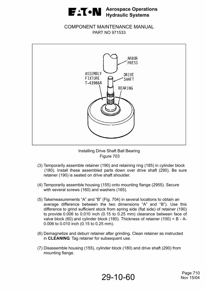
Aerospace OperationsHydraulic Systems
COMPONENT MAINTENANCE MANUALPART NO 971533
29-10-60
Installing Drive Shaft Ball Bearing Figure 703
(3) Temporarily assemble retainer (190) and retaining ring (185) in cylinder block (180). Install these assembled parts down over drive shaft (290). Be sure
retainer (190) is seated on drive shaft shoulder.
(4) Temporarily assemble housing (155) onto mounting flange (2955). Secure with several screws (160) and washers (165).
(5) Takemeasurements “A” and “B” (Fig. 704) in several locations to obtain an average difference between the two dimensions “A” and “B”). Use thisdifference to grind sufficient stock from spring side (flat side) of retainer (190)to provide 0.006 to 0.010 inch (0.15 to 0.25 mm) clearance between face ofvalve block (60) and cylinder block (180). Thickness of retainer (100) = B - A-0.006 to 0.010 inch (0.15 to 0.25 mm).
(6) Demagnetize and deburr retainer after grinding. Clean retainer as instructedin CLEANING. Tag retainer for subsequent use.
(7) Disassemble housing (155), cylinder block (180) and drive shaft (290) frommounting flange.
Page 710Nov 15/04

Aerospace OperationsHydraulic Systems
COMPONENT MAINTENANCE MANUALPART NO 971533
29-10-60
NOTE: Index numbers are the same as those shown on IPL Fig. 2.
60. Valve Block 190. Retainer155. Housing 290. Drive Shaft180. Cylinder Block 295. Mounting Flange185. Retaining Ring
Cylinder Block End Play MeasurementsFigure 704
Page 711 Nov 15/04

Aerospace OperationsHydraulic Systems
COMPONENT MAINTENANCE MANUALPART NO 971533
29-10-60
D. Calculate Piston and Shoe Subassembly End Play.
(1) If at parts inspection, it was found necessary to lap piston shoes, ensure thenine individual shoes were lapped within 0.0004 inch (0.010 mm) of eachother. Refer to REPAIR for the lapping of piston shoes.
(2) If locating pin (245, IPL Fig. 2) was removed from yoke (240) install a new pinensuring pin extension from yoke face is 0.024 to 0.029 inch (0.61 to
0.73 mm).
(3) Assemble bearing plate (230) into yoke, ensure recess on face of plateengages locating pin in yoke.
(4) Test this assembly by pressing down on shoe bearing plate. If plate does not seat properly, recheck extension of location pin (245).
(5)Takemeasurements X and Y, Fig. 705. Subtract Y from X, less 0.0015 to 0.0034inch (0.038 to 0.086 mm). The resultant dimension will be used to determinethe selection of shoe retaining plate (220)
Measurements to Determine Piston Shoe ClearanceFigure 705
NOTE: index numbers are the same as those shown on IPL Fig. 2.
225. Piston & Shoe Subassembly230. Bearing Plate240. Yoke
Page 712Nov 15/04

Aerospace OperationsHydraulic Systems
COMPONENT MAINTENANCE MANUALPART NO 971533
29-10-60
NOTE: Shoe retaining plates (220, IPL FIG. 2 through 220D) are graduated in thicknesses from standard through four oversizes (0.003, 0.005, 0.007 and 0.010 inch) (0.08, 0.13, 0.18 and 0.25 mm). Select the proper thickness of retaining plate that will provide piston shoe end play of 0.0015 to 0.0034 inch (0.038 to 0.086 mm) between bearing plate (215) and shoe retaining plate (185).
(6) Tag shoe retainer plate (220, IPL Fig. 2) having the correct thickness for use inassembly.
E. Assemble Yoke Subassembly and Associated Parts.
(1) Assemble in order, control spring seat (270, IPL Fig. 2), inner and outersprings (265 and 260) and spring guide (255) in mounting flange (295) ashown in Fig.702.
(2) Position yoke (240) in mounting flange with pivot ball seated in spring guide (255) recess.
(3) Place assembled parts in holding clamp T-304106 as shown in Fig. 304.
(4) Compress yoke springs (260 and 265) sufficiently to install pintle bearings(235). Install pintle bearing with thin edge on outer race facing the yoke and lipon inner race facing outward.
(5) Remove from holding clamp and reinstall assembled parts on mechanicalPositioner adapter and power arm.
F. Assemble Piston and Shoe Subassembly.
CAUTION: IN THE FOLLOWING OPERATIONS, USE CAUTION TO PREVENTDAMAGE TO PISTON AND SHOE SUBASSEMBLIES. DO NOTALLOW PISTON TO STRIKE ONE ANOTHER OR OTHER METALSURFACES.
(1) Carefully assemble in yoke (240, IPL Fig. 2), shoe bearing plate (230), nine piston and shoe subassemblies (225), piston shoe retaining plate(220)(selected in paragraph 4D) and retainer (215) (with bronze face againstyoke), and secure finger tight with screws (205) and washers (210).
(2) Using a criss-cross method, torque screws (205) first to 10 to 12 pound inches(1.1 to 1.4 Nm) and then to 24 to 28 pound inches (2.7 to 3.2 Nm).
G. Assemble and Install Cylinder Block.
CAUTION: IN THE FOLLOWING STEPS,USE CAUTION TO PREVENT DAMAGE TO VALVING FACE OF CYLINDER BLOCK AND TO PISTON AND SHOE SUBASSEMBLIES.
Page 713Nov 15/04

Aerospace OperationsHydraulic Systems
COMPONENT MAINTENANCE MANUALPART NO 971533
29-10-60
(1) Assemble in order, seat (200, IPL Fig. 2), cylinder block spring (195) and retainer (190) in cylinder block (180).
NOTE: A retainer (190) of proper thickness was obtained in paragraph 4C, use this retainer in this assembly.
(2) Using spring compressor T-443827 as shown in Fig. 303, compress spring(195) sufficiently to allow installation of retaining ring (185). Install retaining ring and remove cylinder block from spring compressor.
(3) Carefully install cylinder block (180, IPL Fig. 2) with assembled parts on drive shaft (290) and piston and shoe subassemblies (225).
(4) Test assembly by alternately pulling up and pushing down on cylinder block several times. Also rotate cylinder block. There shall be no evidence of binding or roughness.
H. Assembly and Install Housing Subassembly and Associated Parts.
(1) If removed, install new inserts (170, IPL Fig. 2) in housing in accordance withMS33537 and remove tangs.
(2) Install actuator piston (175, IPL Fig. 2) in piston bore of housing (155).
(3) Place finger over hydraulic passageway in housing, to retain actuator piston inhousing, and carefully position housing on mounting flange (295).
(4) Secure housing to mounting flange with screws (160) and washers (165) finger tight.
(5) Using a criss-cross method, torque screws (160) first to 30 - 35 pound inches (3.4-4.0 Nm) and then 60 - 65 pound inches (6.8 - 7.3 Nm).
(6) Install packing (95) in groove in housing.
I. Install Valve Block and Spool Subassembly.
(1) If removed, install a new alignment pin (85, IPL Fig. 2) in valve block (60).
CAUTION: USE EXTREME CARE IN THE FOLLOWING STEP TO PREVENT DAMAGE TO VALVING FACE OF VALVE BLOCK.
(2) Using assembly fixture T-443364 and bearing driver T-424758 as shown in Fig.706, install needle bearing (80) in valve block (60). Press needle bearing in flush or up to 0.010 inch (0.25 mm) below valving face. Do not bottom bearing in bore.
Page 714Nov 15/04

Aerospace OperationsHydraulic Systems
COMPONENT MAINTENANCE MANUALPART NO 971533
29-10-60
Installation of Roller BearingFigure 706
(3) Install packing (90) in groove in valve block pilot.
(4) Install valve block (60) on housing (155) and secure with screws (65) finger tight.
(5) Using a criss -cross method, torque screws (75) first to 30 - 35 pound inches (3.4 - 4.0 Nm) and then 60 - 65 pound inches (6.8 - 7.3 Nm).
(6) Install spool (70) in valve block pressure compensator bore.
J. Assemble Shaft Seal Subassembly.
NOTE: Fig. 707 provides a cross section view of shaft seal subassembly. See this figure for parts location and IPL Fig. 2 of parts identification.
CAUTION: USE CARE NOT TO SCORE SEALING DIAMETEROF DRIVE SHAFT IN THE FOLLOWING STEPS.
(1) Measure depth of shaft seal cavity, dimension “A”, as shown in Fig. 707.
(2) Subtract thickness of mating ring (110, IPL Fig. 2), “dimension “B”, from depth of shaft seal cavity, dimension “A”, to obtain shaft seal working cavity, dimension “C”.
Page 715Nov 15/04

Aerospace OperationsHydraulic Systems
COMPONENT MAINTENANCE MANUALPART NO 971533
29-10-60
Shaft Seal Subassembly, Cross Section ViewFigure 707
(3) Remove stock from shaft seal spacer (140) to obtain a shaft seal load of 8.0 -10.0 lbs. (3.63 - 4.53 kg) in the shaft seal working cavity dimension “C”.
(4) Carefully install retainer (150) on end of shaft and bearing subassembly (280). Be sure tongue of retainer engage drilled holes in drive shaft properly.
(5) Insert wave washer (145) and shaft seal spacer (140) into retainer (150).
CAUTION: USE CARE WHEN HANDLING SHAFT SEAL ELEMENT (125). THIS PART HAS A LAPPED FACE THAT MATES WITH MATING RING (110).
(6) Install garter spring (135) on grommet (130). Using shaft seal guide, T-420868, install grommet and spring on shaft. Remove seal guide from shaft and install shaft seal element (125) in retainer (150) on drive shaft.
(7) Carefully install shaft seal element (1255) on shaft.
100. Retaining Plate 130. Grommet 150. Retainer110. Mating Ring 135. Garter Spring 285. Bearing115. Preformed 140. Shaft Seal 290. Drive Shaft Packing Spacer125. Shaft Seal 145. Wave Spring Element
Page 716Nov 15/04

Aerospace OperationsHydraulic Systems
COMPONENT MAINTENANCE MANUALPART NO 971533
29-10-60
CAUTION: USE CARE WHEN HANDLING MATINGRING (110). THIS PART HAS A LAPPED FACE THAT MATES WITH SHAFT SEAL ELEMENT (125).
(8) Assemble preformed packing (115) on mating ring (110) and carefully installmating ring with chamfered OD against shaft seal element (125).
(9) Install retainer plate (100) and secure with screws (105). Torque screws (105) to 14 - 15 pound inches (1.58 - 1.7 Nm).
K. Assemble Pressure Compensator.
(1) Assemble in order, spring seat (45, IPL Fig. 2), spring (50) and spring guide(45) in valve block (60) pressure compensator bore.
(2) Install packing (40) on adjusting screw (35) and install adjusting screw in valve block.
(3) Install locking nut (30) on adjusting screw. Torquing of locking nut and lockwiring will be performed in testing.
(4) Install packings (25) on two sealing screws (20) and install screws in valve block.Torque screws 15 - 20 pound inches (1.7-2.3 Nm) and secure with
lockwire (320)per MS33540.
(5) Remove hydraulic pump from mechanical positioner adapter.
L. Install Coupling Shaft.
(1) Install packing (10, IPL Fig. 2) and retaining ring (15) on coupling shaft (5).
(2) Fill drive shaft (290) coupling chamber one third full and coat coupling shaft splines with Royco C-201 grease.
(3) Insert coupling shaft into drive shaft. Be sure retaining ring secures coupling shaft in place.
M. Check Drive Shaft Rotation.
(1) After completing the assembly of pump and before plugging inlet and outlet ports, test the assembly for freedom of drive shaft rotating. Shaft shall turn relatively free without an indication of binding at any point.
(2) Plug outlet, seep drain, case drain and inlet ports with plugs (325, IPL Fig. 2, 335, 345 and 355) and packings (330, 340, 350 and 360).
Page 717Nov 15/04

Aerospace OperationsHydraulic Systems
COMPONENT MAINTENANCE MANUALPART NO 971533
29-10-60
NOTE: If hydraulic pump is to be placed in storage for any length of time beforetesting and/or mating with electric motor, refer to paragraph 6.
5. Assemble Motorpump Assembly.
NOTE: The abbreviation IPL refer to the ILLUSTRATED PARTS LIST of this manual. Refer to IPL Fig. 1 for assembly of hydraulic motorpump assembly.
A. Assemble Shock Mount Subassemblies.
CAUTION: DURING ASSEMBLY OF SHOCK MOUNT SUBASSEMBLIES (25), HOLD SHOCK MOUNT (45) WRENCHING FLATS TO PREVENT DAMAGE TO SHOCK MOUNT.
(1) If shock mount subassemblies (25, IPL Fig. 1) were disassembled, thread stud(40) into shock mount (45) while holding mount by wrenching flats.
(2) Torque studs 100 - 105 pound inches (11.3 - 11.9 Nm). Be sure to hold shockmounts by wrenching flats.
(3) Install shock mount subassemblies on electric motor (50) footings and securewith nuts (30) and washers (35). Torque nuts 72 - 76 pound inches (8.1 - 8.6Nm). Be sure to hold shock mounts by wrenching flats.
B. Assemble Hydraulic Pump to Electric Motor.
(1) Install gasket (20, IPL Fig. 1) on electric motor (50) mounting flange.
(2) Fill electric motor drive shaft coupling chamber one third full and coat matingcoupling shaft spline of pump (5) with grease MIL-G-21164.
(3) Install hydraulic pump (5) on electric motor (50) mounting flange and secure withnuts (10) and washers (15). Torque nuts 72 - 76 pound inches (8.1 - 8.6 Nm).
Page 718Nov 15/04
Aerospace OperationsHydraulic Systems
COMPONENT MAINTENANCE MANUALPART NO 971533
29-10-60
6. Storage After Assembly.
A. Preservation.
The following table lists items necessary for adequate storage of these hydraulic motorpump assemblies after repair and test. In addition to these items, each user will have established his own procedures for storage/shipment functions as they relate to his respective operations.
Storage MaterialTable 703
B. Procedure.
Fill to 90% capacity with recommended clean hydraulic fluid. Plug and cap all port openings.
NOTE: Pump must be filled with fluid for corrosion prevention. Fluid from teststand can be used if cleanliness exceeds SAE AS4059, Class 7 level. If teststand fluid cleanliness levels are not maintained, flush and fill with clean fluid.
C. Long Term Storage.
The following recommendation outlines the steps necessary to provide satisfactory storage of units for periods of up to five years. Generally, replacement of synthetic rubber parts is not required during the storage period when these recommendations are followed. As a precautionary measure, seals should be changed in any units stored in excess of five years.
PART NUMBER NAME QTY
186104 Plug, Outlet (Shipping) 1
NAS1612-4 Packing, Preformed (Shipping) 1
186104 Plug, Seep (Shipping) 1
NAS1612-4 Packing, Preformed (Shipping) 1
186104 Plug, Case Drain (Shipping) 1
NAS1612-4 Packing, Preformed (Shipping) 1
212662 Plug, Inlet (Shipping) 1
NAS1612-6 Packing, Preformed (Shipping) 1
Hydraulic Fluid Alkyl Phosphate Ester Base AR
Page 719 Nov 15/04
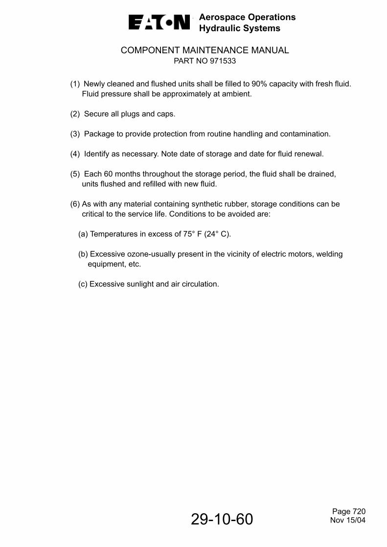
Aerospace OperationsHydraulic Systems
COMPONENT MAINTENANCE MANUALPART NO 971533
29-10-60
(1) Newly cleaned and flushed units shall be filled to 90% capacity with fresh fluid.Fluid pressure shall be approximately at ambient.
(2) Secure all plugs and caps.
(3) Package to provide protection from routine handling and contamination.
(4) Identify as necessary. Note date of storage and date for fluid renewal.
(5) Each 60 months throughout the storage period, the fluid shall be drained, units flushed and refilled with new fluid.
(6) As with any material containing synthetic rubber, storage conditions can be critical to the service life. Conditions to be avoided are:
(a) Temperatures in excess of 75° F (24° C).
(b) Excessive ozone-usually present in the vicinity of electric motors, welding equipment, etc.
(c) Excessive sunlight and air circulation.
Page 720 Nov 15/04

Aerospace OperationsHydraulic Systems
COMPONENT MAINTENANCE MANUALPART NO 971533
29-10-60
THIS PAGE LEFT BLANK INTENTIONALL
Page 721 Nov 15/04

Aerospace OperationsHydraulic Systems
COMPONENT MAINTENANCE MANUALPART NO 971533
FITS AND CLEARANCES
1. Service Wear Limits.
Table 801 lists all critical fits and clearances that must be maintained among the various parts during assembly of the hydraulic pump assembly. Illustrations (Fig.801) are provided where necessary to clarify the location of the itemized dimension
Fits and Clearances TableTable 801 (Sheet 1 of 6)
Fig.801Ref.Ltr.
IPLFigureandItem No. Name
In-Service Wear Limits
Inches Millimeters2-5 Coupling Shaft
Both ends measuredover standard 0.600 inch(1.524 mm) diameter pingages: 0.459 min. 11.66 min.
2-50 Compensator SpringLoad at compressed height of:
Load at compressed height of:
1.008 inchat 37.0± 1.9 lb.
0.935 inch51.66 ± 2.6 lb.
25.60 mm at16.78 ± 0.86kg.
23.75 mm at23.43 ± 1.18 kg.
A
B
C
D
E
2-60 Valve Block and Spool Subassembly Diametral clearance between valve block bore
and spool (70):
Surface finish on mating valving block bore and spool OD:Surface finish of valvingface:Flatness of valving face:
Needle bearing bore ID:
0.0004 max.0.0014 to 0.0016
4 micro inch
4 micro inch3 helium lightbands max.0.5007 max.
0.010 max.0.036 to 0.041
0.10 micron
0.1 micron3 helium lightbands max.12.718 max.
Page 801
29-10-60 Nov 15/04
Aerospace OperationsHydraulic Systems
COMPONENT MAINTENANCE MANUALPART NO 971533
Fits and Clearances Table Table 801 (Sheet 2)
Fig.801Ref.Ltr.
IPLFigureandItem No. Name
In-Service Wear Limits
Inches Millimeters
FG
H
I
2-110 Mating RingOverall ThicknessSealing face flatness:
Sealing face parallel withback face within:Surface finish on sealing face:
0.266 min.2 helium lightbands max.
0.0005 max.
2 micro inch
6.76 min,2 helium lightbands max.
0.013 max.
0.05 micron2-120 Shaft Seal Subassembly
Load at compressed height of 0.321 inch (8.15mm): (See Fig. 707 and refer to ASSEMBLY).
9.0 ±1.0 lb. 4.08 ± 0.45kg.
J
K
LMN
O
2-125 Shaft Seal ElementSealing face extension:Sealing face surface finish:Overall thickness:Back face flatness within:Sealing face flatness:
Surface finish on backface:
0.005 min.
4 micro inch0.155 min.
0.0005 max.3 helium light bands max.16 micro inch
0.13 min.
0.1 micron3.94 min.
0.013 max.
3 helium lightbands max.0.4 micron
2-145 Spring Wave WasherLoad at compressed heightof 0.050 inch (1.27 mm):Do not compress below:
9.0 ±1.0 lb.0.041
4.08 ± 0.45 kg.1.04
P
Q
2-155 Housing Subassembly Surface finish of actuatorpiston (175) bore:Clearance between pistonbore ID and actuator piston(175) OD:
32 micro inch
0.0013 max.
0.8 micron
0.033 max.
29-10-60 Page 802 Nov 15/08

Aerospace OperationsHydraulic Systems
COMPONENT MAINTENANCE MANUALPART NO 971533
Fits and Clearances Table Table 801 (Sheet 3)
Fig.801Ref.Ltr.
IPLFigure
andItem No. Name
In-Service Wear Limits
Inches Millimeters
R
S
2-175 Actuator Piston Surface finish of piston OD: Clearance between piston OD and housing bore ID:
8 micro inch
0.0013 max.
0.2 micron
0.033 max.
T
UV
W
X
2-120 Cylinder Block(Measure piston bore size asshown in Fig. 503 (9 places)):Clearance between bore ID and
piston OD: Center recess depth:Valving face flatness:
Surface finish of valving face: Internal splines measured between standard diameter gage pins:
0.0010 max.0.005 min. 4 helium lightbands max.
4 micro inch
0.3317 max. between 0.0540 diameter pins
0.025 max.0.13 min.4 helium lightbands max.
0.1 micron
8.425 max.between 1.372diameter pins
2-195 Spring (Cylinder Block)Load at compressed height of: 0.450 inch at
30 ± 3.0 lbs. 11.43 mm at13.6 ± 1.4 kg.
YZ AA
2-215 Retainer PlateSurface flatness on bronze face: Surface finish on bronze face: Thickness of bronze plating:
0.001 max.16 micro inch0.005 min.
0.03 max.0.4 micron0.13 min.
2-220 Piston Shoe Retaining PlateBoth faces flat within: Surface finish (both faces):
0.0002 max.16 micro inch
0.005 max. 0.4 micron
Page 803
29-10-60 Nov 15/04
Aerospace OperationsHydraulic Systems
COMPONENT MAINTENANCE MANUALPART NO 971533
29-10-60
Fits and Clearances Table Table 801 (Sheet 4)
Fig.801Ref.Ltr.
IPLFigure
andItem No. Name
In-Service Wear Limits
Inches Millimeters
AB
ACADAE
AF
AG
AH
2-225 Piston and Shoe Subassembly Clearance between piston OD and ID bore of cylinder block: Surface finish on OD of piston: Piston-to-shoe end play:Surface finish on shoe bearing face: Surface finish on shoe toretainer plate (220) mating surfaces: Depth of shoe counter bore:
Thickness of all shoes in one set within:
0.0010 max.
8 micro inch 0.005 max.
8 micro inch
16 micro inch0.005 min.
0.0004 max.
0.025 max
0.2 micron 0.13 max.
0.2 micron
0.4 micron0.13 min.
0.010 max.
AI
AJ
AK
2-230 Shoe Bearing PlateSurface finish on shoe mating face: Flatness of shoe mating face:
Surface parallel within: Overall thickness:
4 micro inch
4 helium lightbands max.0.0002 max. 0.057 min.
0.1 micron
4 helium lightbands max.0.005 max. 1.45 min.
AL
AM
AN
2-240 Yoke, Ball and Pin SubassemblySurface finish on yoke trunnions:
Diametral clearance betweenID of pintle bearing (235)and OD of trunnion:
Extension of locating pin (245):
32 micro inch
0.0010 max.
0.024 to 0.029
0.8 micron
0.025 max.
0.61 to 0.74
Page 804 Nov 15/04

Aerospace OperationsHydraulic Systems
COMPONENT MAINTENANCE MANUALPART NO 971533
29-10-60
Fits and Clearances Table Table 801 (Sheet 5)
Fig.801Ref.Ltr.
IPLFigure
andItem No. Name
In-Service Wear Limits
Inches Millimeters2-260 Outer Yoke Control Spring
Load at compressed height of 0.743 inches (18.87mm): Load at compressed height of 1.075 inches (27.31mm):
28 ± 2.8 lb.
8.0 ± 0.8 lb.
12.7 ±1.3 kg.
3.63 ± 0.36 kg.2-265 Inner Yoke Control Spring
Load at compressed height of 0.673 inches (17.09mm): Load at compressed height of 1.005 inches (25.53mm):
7.0 ± 0.7 lb.
2.0 ± 0.2 lb.
3.17 ± 0.32 kg.
0.91 ± 0.09 kg.
AO
AP
AQAR
2-290 Drive ShaftInternal splines measured between 0.0574 inch (1.4666 mm) pin gages: External splines measured over 0.0600 inch (1.524 mm) pin gages: AQ OD for needle bearing: AR OD for ball bearing:
0.2896 max.
0.4836 min.0.3118 min.0.5905 min.
7.356 max.
12.283 min.7.920 min.14.999 min.
AS
AT
AU
2-295 Mounting Flange SubassemblyDiametral clearance between ID of mounting flange and OD of pintle bearings (220) Surface finish of mating ring (320) bore OD: Diametral clearance between ID of mounting flange and OD of shaft bearing (275)
0.0010 max.
32 micro inch
0.0010 max.
0. 025 max.
0.8 micron
0.025 max.3-230 Commutator End Bell
Bearing (225A) bore ID: 1.2610 max. 32.029 max.
Page 805 Nov 15/04

Aerospace OperationsHydraulic Systems
COMPONENT MAINTENANCE MANUALPART NO 971533
29-10-60
Fits and Clearances Table Table 801 (Sheet 6)
Fig.801Ref.Ltr.
IPLFigure
andItem No. Name
In-Service Wear Limits
Inches Millimeters3-235 Armature
Bar-to-bar concentricity within: Commutator-to-shaft concentricity within: Commutator diameter
0.0002 max.
0.0008 max.1.900 min.
0.005 max.
0.020 max.48.25 min.
3-250 Drive End Bell Bearing (245A) bore ID: 1.2610 max. 32.029 max.
Page 806 Nov 15/04

Aerospace OperationsHydraulic Systems
COMPONENT MAINTENANCE MANUALPART NO 971533
29-10-60
Fits and Clearances Figure 802 (Sheet 1 of 3)
Page 807Nov 15/04

Aerospace OperationsHydraulic Systems
COMPONENT MAINTENANCE MANUALPART NO 971533
29-10-60
Fits and ClearancesFigure 802 (Sheet 2)
Page 808 Nov 15/04

Aerospace OperationsHydraulic Systems
COMPONENT MAINTENANCE MANUALPART NO 971533
29-10-60
Fits and ClearancesFigure 802 (Sheet 3)
Page 809Nov 15/04

Aerospace OperationsHydraulic Systems
COMPONENT MAINTENANCE MANUALPART NO 971533
29-10-60
2. Torque Values.
Table 802 lists all torque values that must be obtained to assure proper security of attaching parts during assembly of the motorpump assembly.
NOTE: Lubricating threads of attaching parts with clean alkyl phosphate ester hydraulic fluid will assure a more accurate torque reading.
Torque Values Table 802
IPL Fig.and
Item No.Item
Torque
(Pound/Inch) Newton Meters
1-10 Nut 72 to 76 8.1 to 8.6
1-30 Nut 72 to 76 8.1 to 8.6
1-40 Stud, Shock Mounting 100 to 105 11.3 to 11.9
2-20 Screw 15 to 20 1.7 to 2.3
2-35 Screw, Compensator Adj. 35 to 40 4.0 to 45
2-65 Screw 60 to 65 6.8 to 7.3
2-160 Screw 60 to 65 6.8 to 73
2-205 Screw 24 to 28 2.7 to 3.2
3-215 Bolt 30 to 35 3.4 to 4.0
Page 809 Nov15/04

Aerospace OperationsHydraulic Systems
COMPONENT MAINTENANCE MANUALPART NO 971533
29-10-60
THIS PAGE LEFT BLANK INTENTIONALLY
Page 810 Nov 15/04

Aerospace OperationsHydraulic Systems
COMPONENT MAINTENANCE MANUALPART NO 971533
29-10-60
SPECIAL TOOLS, FIXTURES AND EQUIPMENT1. General.
The following special tools and test equipment (Fig. 901) are recommended for the repair and test of this equipment. However, tooling and test equipment other than those listed may be used provided they perform the required operations. See Fig.902 for identification of tools
Special Tools, Fixtures and Equipment TableFigure 901 (Sheet 1 of 2)
TOOL NO. NAME
APPLICATIONT-108684 Master Ring, Air
GageUsed with spindle T-415408 to check cylinder block bores for wear. This ring calibrates low limit reading of air gage.See Fig. 503.
T-219352 Master Ring, Air Gage
Used with spindle T-415408 to check cylinder block bores for wear. This ring calibrates low limit reading of air gage. See Fig. 503.
T-233247 Set, Flushing Used to flush hydraulic pump before and after testing.
T-300664 Adapter, MechanicalPositioner
Used with Power Arm to support hydraulic pump during ASSEMBLY and DISASSEMBLY. See Fig. 301.
T-302537 ”A” Frame Test Stand
Used to secure unit during TESTING.
T-304103 Plate, Bearing Removal
Used with T-304104 driver to remove ball bearing (285) from pump drive shaft. See Fig. 305.
T-304104 Driver, Bearing Used with bearing removal plateT-304103 to remove ball bearing (285) from pump drive shaft. See Fig. 305.
T-304105 Puller, Bearing Used to remove needle bearing (80) from pump valve block. See Fig. 302.
T-304106 Clamp, Holding Used to compress control springs (260 and 265) to remove pintle bearings (235). See Fig. 304.
Page 901Nov 15/04
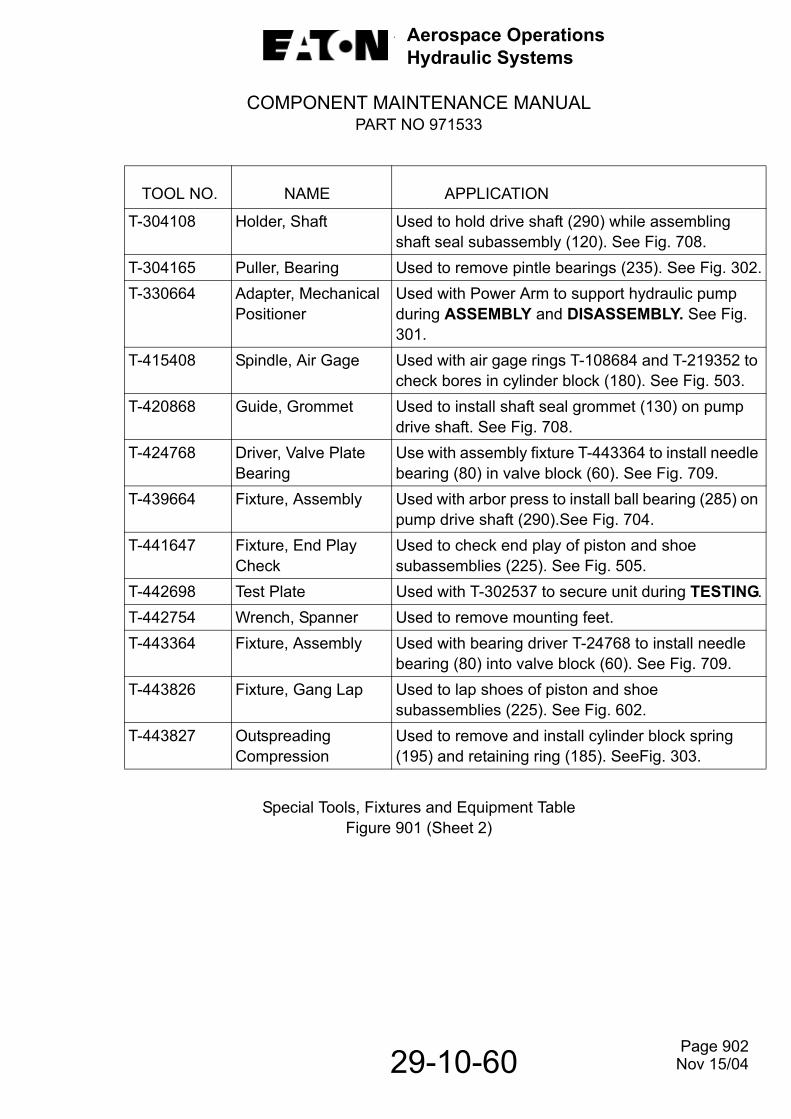
Aerospace OperationsHydraulic Systems
COMPONENT MAINTENANCE MANUALPART NO 971533
29-10-60
Special Tools, Fixtures and Equipment TableFigure 901 (Sheet 2)
TOOL NO. NAME APPLICATION
T-304108 Holder, Shaft Used to hold drive shaft (290) while assembling shaft seal subassembly (120). See Fig. 708.
T-304165 Puller, Bearing Used to remove pintle bearings (235). See Fig. 302.T-330664 Adapter, Mechanical
PositionerUsed with Power Arm to support hydraulic pump during ASSEMBLY and DISASSEMBLY. See Fig. 301.
T-415408 Spindle, Air Gage Used with air gage rings T-108684 and T-219352 to check bores in cylinder block (180). See Fig. 503.
T-420868 Guide, Grommet Used to install shaft seal grommet (130) on pump drive shaft. See Fig. 708.
T-424768 Driver, Valve PlateBearing
Use with assembly fixture T-443364 to install needle bearing (80) in valve block (60). See Fig. 709.
T-439664 Fixture, Assembly Used with arbor press to install ball bearing (285) on pump drive shaft (290).See Fig. 704.
T-441647 Fixture, End PlayCheck
Used to check end play of piston and shoe subassemblies (225). See Fig. 505.
T-442698 Test Plate Used with T-302537 to secure unit during TESTING.T-442754 Wrench, Spanner Used to remove mounting feet.T-443364 Fixture, Assembly Used with bearing driver T-24768 to install needle
bearing (80) into valve block (60). See Fig. 709.T-443826 Fixture, Gang Lap Used to lap shoes of piston and shoe
subassemblies (225). See Fig. 602.T-443827 Outspreading
Compression Used to remove and install cylinder block spring (195) and retaining ring (185). SeeFig. 303.
Page 902 Nov 15/04

Aerospace OperationsHydraulic Systems
COMPONENT MAINTENANCE MANUALPART NO 971533
29-10-60
Special Tools and Test EquipmentFigure 902 (Sheet 1 of 3)
Page 903Nov 15/04
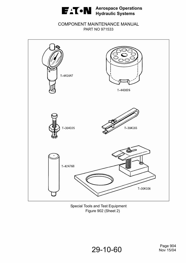
Aerospace OperationsHydraulic Systems
COMPONENT MAINTENANCE MANUALPART NO 971533
29-10-60
Special Tools and Test Equipment Figure 902 (Sheet 2)
Page 904 Nov 15/04

Aerospace OperationsHydraulic Systems
COMPONENT MAINTENANCE MANUALPART NO 971533
29-10-60
Special Tools and Test Equipment Figure 902 (Sheet 3)
Page 905 Nov 15/04

Aerospace OperationsHydraulic Systems
COMPONENT MAINTENANCE MANUALPART NO 971533
29-10-60
THIS PAGE LEFT BLANK INTENTIONALLY
Page 906Nov 15/04

Aerospace OperationsHydraulic Systems
COMPONENT MAINTENANCE MANUALPART NO 971533
29-10-60
ILLUSTRATED PARTS LIST1. Introduction.
A. General.
This Illustrated Parts List is applicable to the Variable Displacement Hydraulic Motor-pump Assembly, Part Number 971533 (Model Number MPEV3-008-6).The purpose of this list is to itemize the parts that comprise and are necessary for the support of these assemblies. It is intended for use in provisioning, requisitioning, storing and issuing replaceable parts.
B. Detail Parts List.
The Detail Parts List has been compiled in accordance with accepted procedure. In general, parts are listed in their order of disassembly and are indented to show their relationship to the next higher assembly.
C. Part Numbering System.
There is no relationship among Eaton-Vickers part numbers since they are assigned as referenced drawings are completed. A given subassembly, for instance, will not necessarily consist of numbers in sequence or in related groups. Numbers shown in the part number column are Vicker’s numbers, with the exception of “AN”, “MS”,“NAS” and Vendor supplied parts. When “AN,” “MS” or “NAS” numbers are shown in the part number column, Vicker’s equivalent numbers appear in the nomenclature column in parentheses, preceded by Vicker’s Code 62983. Vendor part numbers are identified by the vendor’s code (preceded by the letter “V”) immediately following the nomenclature when available. This, in turn, is followed by Vickers Code 62983 and the Vickers part number.
Page 1001 Nov 15/04

Aerospace OperationsHydraulic Systems
COMPONENT MAINTENANCE MANUALPART NO 971533
29-10-60
D. Manufacturer’s Code and Name.
The following list of codes arranged in numerical sequence reflects the names andaddresses of manufacturers supplying items for the equipment in this publication.
Vendor’s Code Vendor’s Name and Address
54395 Electromech Technologies 2600 South Custer Wichita, Kansas 62217
62983 Eaton Aerospace Hydraulic Systems Div.
5353 Highland Drive Jackson, Mississippi 39206
E. Explanation of Symbols and Abbreviations
The abbreviation “REF” is used in the “UNITS PER ASSEMBLY” column in lieu of unit quantity. For the total quantity of the item (and all components of the item) refer to the first listing of the item.
The abbreviation “AR” is used in the “UNITS PER ASSY” column to indicate the quantity of parts to use is “As Required.”The abbreviation “NP” is used in the “Units Per Assembly” column to indicate the parts are “not procurable.”
2. Numerical Index.
The following numerical index is provided to assist the user in locating part numbers in the Detail Parts List. The index is compiled in accordance with accepted procedure.
Page 1002 Nov 15/04

Aerospace OperationsHydraulic Systems
COMPONENT MAINTENANCE MANUALPART NO 971533
29-10-60
PART NUMBERAIRLINE
PART NO. FIG. ITEM TTL REQ.AN3-54AMS35360-3252
AN363-428
AN565DC428H24AN960-8
BPF-5/8C004AA1420ACC007DX1420ACC120AA2420ACF2010A00MIL-W-22759/41-6-9
MS16998-28
MS21083-N08MS21209F0-620
MS21209F1-15
MS3456L24-12PMS3470L833PMS35206-245MS35265-14MS35265-27
MS35266-78MS35275-215MS35333-37
MS35333-39MS35333-40
3-2153-103-1001-101-303-2553-1703-2853-53-603-853-553-653-903-952-652-1603-1652-2502-3102-1702-3053-703-513-2753-523-453-1403-2653-52A3-503-1453-1303-15A
42244444211111148484481
NP4
NP245
NP2442
Page 1003 Nov 15/08

Aerospace OperationsHydraulic Systems
COMPONENT MAINTENANCE MANUALPART NO 971533
29-10-60
PART NUMBER
AIRLINEPART NO. FIG. ITEM TTL REQ.
MS35338-42MS35338-43MS35338-44
MS35489-93MS35650-3252
MS51964-49N5000-125MDNAS1101E06-6NAS1611-008/-008ANAS1611-011/-011A
NAS1611-015/-015ANAS1611-027/-027ANAS1611-118/-118ANAS1612-4/-4A
NAS1612-6/-6A48-11-7000-148-17-1001-148-18-7000-148-5-1009-248-5-101048-5-100148-1-103248-5-100548-5-300048-5-600148-5-200048-5-5000-1
3-2803-2203-153-1053-2703-353-10A3-100A3-1553-1952-1052-252-952-102-402-902-1152-3302-3402-3502-3603-403-35A3-40A3-1203-1253-1353-1503-1603-1903-2303-2353-240
442252221142111111111121141114111
Page 1004 Nov 15/04
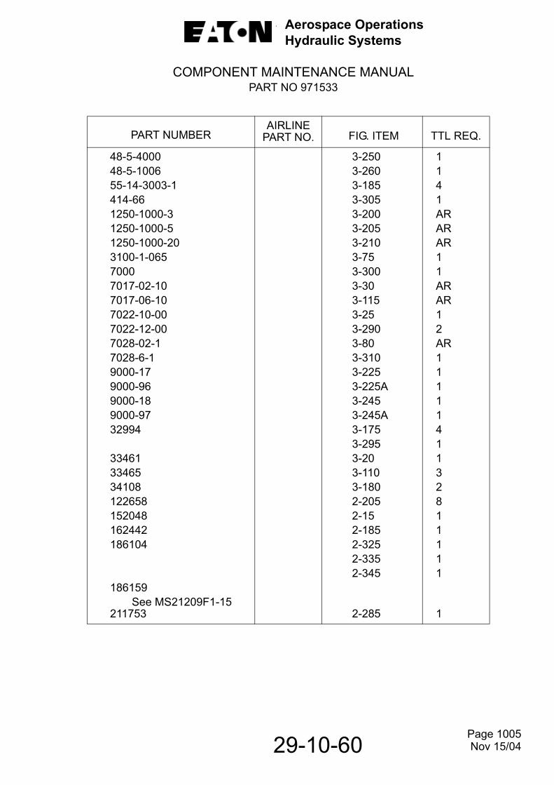
Aerospace OperationsHydraulic Systems
COMPONENT MAINTENANCE MANUALPART NO 971533
29-10-60
PART NUMBER
AIRLINEPART NO. FIG. ITEM TTL REQ.
48-5-400048-5-100655-14-3003-1414-661250-1000-31250-1000-51250-1000-203100-1-06570007017-02-107017-06-107022-10-007022-12-007028-02-17028-6-19000-179000-969000-189000-9732994
334613346534108122658152048162442186104
186159 See MS21209F1-15211753
3-2503-2603-1853-3053-2003-2053-2103-753-3003-303-1153-253-2903-803-3103-2253-225A3-2453-245A3-1753-2953-203-1103-1802-2052-152-1852-3252-3352-345
2-285
1141ARARAR11ARAR12AR1111141132811111
1
Page 1005 Nov 15/04

Aerospace OperationsHydraulic Systems
COMPONENT MAINTENANCE MANUALPART NO 971533
29-10-60
PART NUMBER
AIRLINEPART NO. FIG. ITEM TTL REQ.
212662217438 See MS21209F0-620224946 See MS16998-28248774
271085 See NAS1612-4271087 See NAS1612-6271128 See NAS1611-008271131 See NAS1611-011271135 See NAS1611-015271147 See NAS1611-027271157 See NAS1611-118279326283606297009312468331495331753332539332566332956342047342211342245344947344952
2-355
2-852-300
2-301-202-2352-702-452-202-802-1502-1452-1352-552-502-3152-320
1
12
112
NP1211111111
Page 1006 Nov 15/04

Aerospace OperationsHydraulic Systems
COMPONENT MAINTENANCE MANUALPART NO 971533
29-10-60
PART NUMBER
AIRLINEPART NO. FIG. ITEM TTL REQ.
371687388159406746417355417355570794571500571503571509571528571529571534571537571538571588622119622137622181622182622183622184622185622186622187622262622342622556623980623981
2-1301-602-351-151-352-1251-552-1802-2252-2002-1902-2302-2652-2602-2452-2101-402-1552-2802-602-1752-2402-2902-752-52-1952-2152-2702-255
11144111911111184111111
NP11111
Page 1007 Nov 15/04
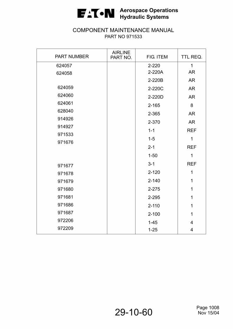
Aerospace OperationsHydraulic Systems
COMPONENT MAINTENANCE MANUALPART NO 971533
29-10-60
PART NUMBER
AIRLINEPART NO. FIG. ITEM TTL REQ.
624057624058
624059
624060
624061
628040
914926
914927
971533
971676
971677
971678
971679
971680
971681
971686
971687
972206
972209
2-2202-220A
2-220B
2-220C
2-220D
2-165
2-365
2-370
1-1
1-5
2-1
1-50
3-1
2-120
2-140
2-275
2-295
2-110
2-100
1-451-25
1AR
AR
AR
AR
8
AR
AR
REF
1
REF
1
REF
1
1
1
1
1
1
44
Page 1008 Nov 15/04

Aerospace OperationsHydraulic Systems
COMPONENT MAINTENANCE MANUALPART NO 971533
29-10-60
Hydraulic Motorpump Assembly, Exploded ViewFigure 1
Page 1009 Nov 15/04

Aerospace OperationsHydraulic Systems
COMPONENT MAINTENANCE MANUALPART NO 971533
29-10-60
- ITEM NOT ILLUSTRATED
FIG.ITEM
PARTNUMBER
AIRLINEPARTNO.
NOMENCLATURE1 2 3 4 5 6 7
EFFECTCODE
UNITSPERASSY
1-
1
5
10 15
20 -25
30 35
40 45 50
55 60
971533
971676
AN363-428417355
283606972209
AN363-428417355
622137342211971677
331495388159
MOTORPUMP, D.C. ELECTRICMOTOR DRIVEN HYDRAULICPUMP ASSEMBLY (MODEL MPEV3-008-6)
. HYDRAULIC PUMP SUBASSEMBLY (SEE IPL FIG. 2 FOR DETAILS) (ATTACHING PARTS)
. NUT (62983 138116)
. WASHER -- -- -- * * * -- -- --. GASKET. SHOCK MOUNT SUBASSEMBLY (ATTACHING PARTS). NUT (62983 138116). WASHER -- -- -- * * * -- -- --. STUD. MOUNT, SHOCK. MOTOR, SUBASSEMBLY, D.C. ELECTRIC (SEE IPL FIG. 3 FOR DETAILS). PLATE, IDENTIFICATION. PLATE, MODIFICATION POST SB 971533-29-01
REF
1
44
14
44
441
11
Page 1010 Nov 15/08

Aerospace OperationsHydraulic Systems
COMPONENT MAINTENANCE MANUALPART NO 971533
29-10-60
Hydraulic Pump Subassembly, Exploded ViewFigure 2
Page 1011 Nov 15/04

Aerospace OperationsHydraulic Systems
COMPONENT MAINTENANCE MANUALPART NO 971533
- ITEM NOT ILLUSTRATED
FIG.ITEM
PARTNUMBER
AIRLINEPARTNO.
NOMENCLATURE1 2 3 4 5 6 7
EFFECTCODE
UNITSPERASSY
2-
1
510
152025
303540
45505560
65
7075
808590
95
100
105
971676
622262NAS1611-011/011A152048331753NAS1611-008/008A279326406746NAS1611-015/015A342211342245331495622183
MS16998-28
312468622187
332539248774NAS1611-027/027ANAS1611-011/011A971687
NAS1101E06-6
PUMP, HYDRAULIC VARIABLE DELIVERY SUBASSEMBLY (SEE ITEM 5, IPL FIG. 1). SHAFT, COUPLING. PACKING, PREFORMED (62983 271131). RING, RETAINING. SCREW, SEALING. PACKING, PREFORMED (62983 271128). NUT, LOCKING. SCREW, ADJUSTING. PACKING, PREFORMED (62983 271135). GUIDE, SPRING. SPRING. SEAT, SPRING. VALVE BLOCK AND SPOOL SUBASSEMBLY (ATTACHING PARTS). SCREW (62983 224946) -- -- -- * * * -- -- --.. . SPOOL. . VALVE BLOCK AND BEARING SUBASSEMBLY. . BEARING, NEEDLE. . PIN, ALIGNMENT. PACKING, PREFORMED (62983 271147). PACKING, PREFORMED (62983 271131). PLATE, RETAINER (ATTACHING PARTS). SCREW (62983 971554)
REF
11
122
111
1111
4
NPNP
111
1
1
4
29-10-60 Page 1012 Nov 15/08

Aerospace OperationsHydraulic Systems
COMPONENT MAINTENANCE MANUALPART NO 971533
- ITEM NOT ILLUSTRATED
FIG.ITEM
PARTNUMBER
AIRLINEPARTNO.
NOMENCLATURE1 2 3 4 5 6 7
EFFECTCODE
UNITSPERASSY
2-
110115
-120125130135140145150155
160165
170175180185190195200205210215
220-220A
971686NAS1611-118/-118A971678570794371687342047971679332956332566622181
MS16998-28628040
MS21209F1-15622184571503162442571529622342571528122658622119622556
624057624058
-- -- -- * * * -- -- --.RING, MATING.PACKING, PREFORMED (62983 271157). SHAFT SEAL SUBASSEMBLY. . ELEMENT, SHAFT SEAL. . GROMMET. . SPRING, GARTER. . SPACER, SHAFT SEAL. . SPRING, WAVE. . RETAINER. HOUSING AND INSERTS SUBASSEMBLY (ATTACHING PARTS). SCREW (62983 224946). WASHER -- -- -- * * * -- -- --. .INSERT (62983 186159).PISTON, ACTUATOR.CYLINDER BLOCK.RING, RETAINING.RETAINER.SPRING.SEAT.SCREW.WASHER.RETAINER.PLATE, PISTON SHOE RETAINING.PLATE, PISTON SHOE RETAINING (0.003 (0.08 MM) OVERSIZE)
11
11111111
88
41111118811
AR
29-10-60 Page 1013 Nov 15/04

Aerospace OperationsHydraulic Systems
COMPONENT MAINTENANCE MANUALPART NO 971533
- ITEM NOT ILLUSTRATED
FIG.ITEM
PARTNUMBER
AIRLINEPARTNO.
NOMENCLATURE1 2 3 4 5 6 7
EFFECTCODE
UNITSPERASSY
2-
-220B
-220C
-220D
225
230 235 240
245 250
255 260 265 270 275-280
285 290-295
300 305 310
315 320-325
624059
624060
624061
571509
571534297009622185
571588MS21209F0-620623981571538571537623980971680622182
211753622186971681
248774MS21209F1-15MS21209F0-620344947344952186104
.PLATE, PISTON SHOE RETAINING (0.005 (0.13MM) OVERSIZE).PLATE, PISTON SHOE RETAINING (0.007 (0.18MM) OVERSIZE).PLATE, PISTON SHOE RETAINING (0.010 (0.25MM) OVERSIZE).PISTON AND SHOE SUBASSEMBLY.PLATE, SHOE BEARING.BEARING, PINTLE.YOKE, BALL, AND PIN SUBASSEMBLY. .PIN, LOCATING. .INSERT (62983 217438)
.GUIDE, SPRING
.SPRING, OUTER
.SPRING, INNER
.SEAT, CONTROL SPRING
.PACKING, PREFORMED
.SHAFT AND BEARING SUBASSEMBLY.. BEARING, BALL..SHAFT, DRIVE.MOUNTING, FLANGE SUBASSEMBLY. .PIN, ALIGNING. .INSERT (62983 186159). .INSERT (62983 217438)
.PLATE, ROTATION
.PLATE, INSTRUCTION
.PLUG, OUTLET
AR
AR
AR
9
121
18
111111111
284
111
Page 1014
29-10-60 Nov 15/04
Aerospace OperationsHydraulic Systems
COMPONENT MAINTENANCE MANUALPART NO 971533
- ITEM NOT ILLUSTRATED
FIG.ITEM
PARTNUMBER
AIRLINEPARTNO.
NOMENCLATURE1 2 3 4 5 6 7
EFFECTCODE
UNITSPERASSY
2-
-330
-335-340
-345-350
-355-360
-365-370
NAS1612-4/-4A186104NAS1612-4/-4A186104NAS1612-4/-4A212662NAS1612-6/-6A914926914927
.PACKING. PREFORMED (62983 271085).PLUG, SEEP.PACKING, PREFORMED (62983 271085).PLUG, CASE DRAIN.PACKING, PREFORMED (62983 271085).PLUG, INLET.PACKING, PREFORMED (62983 271087).KIT, SEALING.KIT, OVERHAUL
1
11
11
11
ARAR
29-10-60 Page 1015 Nov 15/04

Aerospace OperationsHydraulic Systems
COMPONENT MAINTENANCE MANUALPART NO 971533
29-10-60
Electric Motor Subassembly, Exploded ViewFigure 3
Page 1016 Nov 15/04

Aerospace OperationsHydraulic Systems
COMPONENT MAINTENANCE MANUAL
PART NO 971533- ITEM NOT ILLUSTRATED
FIG.ITEM
PARTNUMBER
AIRLINEPARTNO.
NOMENCLATURE1 2 3 4 5 6 7
EFFECTCODE
UNITSPERASSY
3
1
510
10A
152025
30
35
35A
40
40A
4550
5152
52A
55
971677
3032681-300AN345-416
MS35650-3252
MS35338-443032681-3013032681-302
3032681-303
MS35489-93
3032681-304
3032681-305
3032681-306
MS35265-27MS35333-37
MS3470L833PMS35265-14
MS35275-215
3032681-307
MOTOR SUBASSEMBLY, D.C. ELECTRIC (SEE ITEM 50, IPL FIG. 1) (V54395 971677). CAP PLUG (V54395 BPF-5/8). NUT SUPSD BY ITEM 10A. NUT SUPSDS ITEM 10. LOCKWASHER. TERMINAL (V54395 33461). WIRE, LEAD (10--GAUGE BLK, 30 IN. (762 MM) LONG) (V54395 7022-10-00). SLEEVING, NO. 2 (V54395 7017-02-10). BUSHING, RUBBER SUPSD BY ITEM 35A. GROMMET (V54395 48-17- 1001-1) SUPSDS ITEM 35. FILTER ASSEMBLY (V54395 48-11-7000-1) SUPSD BY ITEM 40A. FILTER ASSEMBLY (V54395 48-18-7000-1) SUPSDS ITEM 40 (ATTACHING PARTS). SCREW. LOCKWASHER -- -- -- * * * -- -- --. . CONNECTOR, ELECTRICAL. . SCREW SUPSD BY ITEM 52A. . SCREW SUPSDS ITEM 52. ADAPTER, CONNECTOR (V54395 C120AA2420AC)
REF
22
2
211
AR
2
2
1
1
22
NPNP
NP
1
Page 1017
29-10-60 Nov 15/08
Aerospace OperationsHydraulic Systems
COMPONENT MAINTENANCE MANUAL
PART NO 971533- ITEM NOT ILLUSTRATED
FIG.ITEM
PARTNUMBER
AIRLINEPARTNO.
NOMENCLATURE1 2 3 4 5 6 7
EFFECTCODE
UNITSPERASSY
3
60
657075
80
85
90
95
100
100A
105110115
120
125130
135
140145155
3032681-308
3032681-309MS3456L24-12P3032681-310
3032681-311
3032681-312
MIL-W-22759/41-6-9
MIL-W-22759/41-6-9
AN345-416
MS35650-3252
MS35338-443032681-3133032681-314
3032681-315
3032681-316MS35333-39
3032681-317
MS35265-27MS35333-37MS51964-49
. ADAPTER, FEMALE (V54395 C004AA1420AC). CONDUIT (V54395 F2010A00). CONNECTOR. THERMOSTAT (V54395 3100-1-065). HEATSHRINK (V54395 7028-02-1). ADAPTER, BULKHEAD (V54395 C007DX1420AC). WIRE, LEAD WHITE 30 IN. (762 mm) LONG) (P/N CORRECTION). WIRE, LEAD WHITE 30 IN. (762 mm) LONG) (P/N CORRECTION). NUT SUPSD BY ITEM 100A. NUT SUPSDS ITEM 100. LOCKWASHER. TERMINAL (V54395 33465). SLEEVING, NO. 6 (V54395 7017-06-10). SHROUD, ASSEMBLY (V54395 48-5-1009-2) (ATTACHING PARTS). SCREW (V54395 48-5-1010). LOCKWASHER -- -- -- * * * -- -- --. COVER ASSEMBLY (V54395 48-5-1001) (ATTACHING PARTS). SCREW. LOCKWASHER . SETSCREW
1
1 1 1
AR
1
1
1
2
2
2 3 AR
1
4 4
1
4 4 1
Page 1018
29-10-60 Nov 15/08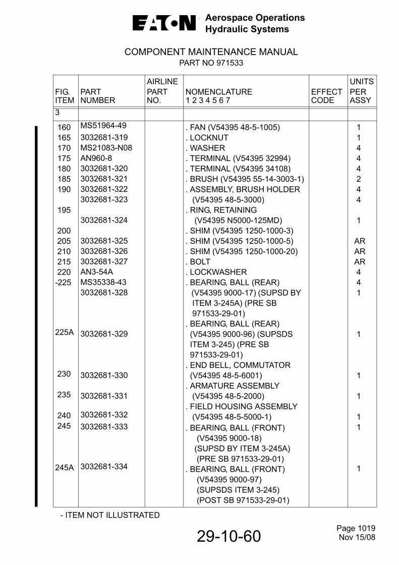
Aerospace OperationsHydraulic Systems
COMPONENT MAINTENANCE MANUALPART NO 971533
29-10-60 - ITEM NOT ILLUSTRATED
FIG.ITEM
PARTNUMBER
AIRLINEPARTNO.
NOMENCLATURE1 2 3 4 5 6 7
EFFECTCODE
UNITSPERASSY
3
160 165 170 175 180 185 190
195
200 205 210 215 220-225
225A
230
235
240 245
245A
MS51964-493032681-319MS21083-N08AN960-83032681-3203032681-3213032681-3223032681-323
3032681-324
3032681-3253032681-3263032681-327AN3-54AMS35338-433032681-328
3032681-329
3032681-330
3032681-331
3032681-3323032681-333
3032681-334
. FAN (V54395 48-5-1005)
. LOCKNUT
. WASHER
. TERMINAL (V54395 32994)
. TERMINAL (V54395 34108)
. BRUSH (V54395 55-14-3003-1)
. ASSEMBLY, BRUSH HOLDER (V54395 48-5-3000). RING, RETAINING (V54395 N5000-125MD). SHIM (V54395 1250-1000-3). SHIM (V54395 1250-1000-5). SHIM (V54395 1250-1000-20). BOLT. LOCKWASHER. BEARING, BALL (REAR) (V54395 9000-17) (SUPSD BY ITEM 3-245A) (PRE SB 971533-29-01). BEARING, BALL (REAR) (V54395 9000-96) (SUPSDS ITEM 3-245) (PRE SB 971533-29-01). END BELL, COMMUTATOR (V54395 48-5-6001). ARMATURE ASSEMBLY (V54395 48-5-2000). FIELD HOUSING ASSEMBLY (V54395 48-5-5000-1). BEARING, BALL (FRONT) (V54395 9000-18) (SUPSD BY ITEM 3-245A) (PRE SB 971533-29-01). BEARING, BALL (FRONT) (V54395 9000-97) (SUPSDS ITEM 3-245) (POST SB 971533-29-01)
1 1 4 4 4 2 4 4
1
AR AR AR 4 4 1
1
1
1
1 1
1
Page 1019 Nov 15/08

Aerospace OperationsHydraulic Systems
COMPONENT MAINTENANCE MANUALPART NO 971533
29-10-60
- ITEM NOT ILLUSTRATED
FIG.ITEM
PARTNUMBER
AIRLINEPARTNO.
NOMENCLATURE1 2 3 4 5 6 7
EFFECTCODE
UNITSPERASSY
3
250
255260
265
265A
270
270A
271
275280285290
295300305
310
315320325
3032681-335
AN565DC428H243032681-336
MS35266-78
MS35266-77
MS35338-44
MS35338-40
AN960-416L
MS35206-245MS35338-42AN960-83032681-337
3032681-32070003032681-340
3032681-341
MS3348-4-6MS20995C32MS20995C20
. DRIVE END BELL ASSEMBLY (V54395 48-5-4000). . BOLT. BASE, MOUNTING (V54395 48- 5-1006) ATTACHING PARTS. SCREW SUPSD BY ITEM 265A. SCREW SUPSDS ITEM 265. LOCKWASHER SUPSD BY ITEM 270A. LOCKWASHER SUPSDS ITEM 270. WASHER, FLAT-- -- -- * * * -- -- --. SCREW. LOCKWASHER. WASHER. WIRE (12-GAUGE, BLACK (V54395 7022-12-00) 7 IN. (178 mm) LONG). TERMINAL (V54395 32994). DELETE. PLACARD, WARNING (V54395 414-66). HEATSHRINK (.5’) (V54395 7028-6-1). BUSHING, CONTACT. WIRE, SAFETY. WIRE, SAFETY
1
41
5
5
5
5
5
4442
111
1
2ARAR
Page 1020 Nov 15/08

Aerospace OperationsHydraulic Systems
COMPONENT MAINTENANCE MANUALPART NO 971533
29-10-60
THIS PAGE LEFT BLANK INTENTIONALLY
Page 1021 Nov 15/04