clow canada · m67 brigadier / m93 brigadier / mcavity m67 dry barrel fire hydrant operation and...
TRANSCRIPT

CLOW CANADA
2017
04/01/18
Brigadier Fire Hydrant Operation & Maintenance
Revision: Release 5
Approved: Rick Benoit
CLOW CANADA
Brigadier Fire Hydrant Operation and Maintenance Manual
Click Here For Hydrant
Maintenance Video!
RETURN TO CONTENTS
1

CLOW CANADA
M67 Brigadier / M93 Brigadier / McAvity M67 Dry Barrel Fire Hydrant Operation and Maintenance Manual
Table of Contents Introduction/Description/Certifications .............................................................................................. 3-4
3D/2D Parts Illustration & Bill of Materials ........................................................................................5-10
Receiving & Handling/Storage .............................................................................................................. 11
Identification of Fire Hydrants ......................................................................................................... 12-16
McAvity Hydrant Interchangeability Table ............................................................................................ 17
Chronology of Clow Hydrants ............................................................................................................... 18
Special Hydrants .................................................................................................................................. 19
Heritage Style Hydrant ................................................................................................................................ 19
Ductile Iron Flanged Elbow ......................................................................................................................... 19
Monitor Hydrant 3D Explosion ................................................................................................................... 20
In-Line Chamber (Deep D.O.B. Hydrants 14’+) 3D Explosion ..................................................................... 21
On-Line Hydrant 3D Explosion .................................................................................................................... 22
Fire Hydrant Ordering Specifications Checklist ...................................................................................... 23
Installation & Testing ........................................................................................................................... 24
Tools Required for Maintenance/Repair .......................................................................................... 24-27
Pre-Assembled Fire Hydrant Repair Kits .......................................................................................... 28-32
Instructions for Extending .................................................................................................................... 33
Regular Maintenance Procedures .................................................................................................... 34-37
Repair Procedures ............................................................................................................................... 37
Hydra-Lube Operating Nut Conversion Kit ............................................................................................ 37-39
Complete Upper Body & Stem Conversion Kit ...................................................................................... 40-41
Plugging A Self Draining Hydrant ................................................................................................................ 42
Changing Nozzles ................................................................................................................................... 43-44
Troubleshooting Guide ................................................................................................................... 45-46
Warranty ........................................................................................................................................ 47-48
RETURN TO CONTENTS
2

M67 Brigadier / M93 Brigadier / McAvity M67 Dry Barrel Fire Hydrant
Operation and Maintenance Manual
Clow Canada's Brigadier fire hydrant incorporates several new design features and improved components for increased performance in firefighting, along with greater durability, economy and convenience. These hydrants are manufactured in Canada to the highest standards of quality. Every unit is hydrostatically tested in accordance with ULC/FM procedure before leaving the Clow factory.
Lubrication is assured through the Brigadier's unique Hydra-lube™ mechanism. The Brigadier can be rotated to any position during or after installation without disturbing the internal working mechanism. The rugged Brigadier fire hydrant stands up easily to traffic damage. It is designed for easy upkeep, repair and replacement of parts; its internal assembly can be removed and replaced in 20 minutes, without excavation. Alternative design options and accessories serve a wide range of municipal and industrial needs. The Brigadier's advantages include:
✓ Complete inter-changeability with previous M-67 and M-59-M model hydrants
✓ Conforms to AWWA C502 specifications
✓ All hydrants are ULC listed & FM approved
✓ Efficient compression-type hydrant
RETURN TO CONTENTS
3

✓ Factory-lubricated operating mechanism effectively O-ring sealed for long and
efficient operation
✓ Very low opening and closing torques
✓ Automatic drainage
✓ Available quick connect Storz hose & pumper connections
✓ Positive sealing with O-rings at operating nut, operating housing, bronze casing and
seat
✓ Durable and positive seating
✓ Easy multiple positioning
✓ Safety stem coupling and four safety segments
✓ Internal parts easily removed -bury easily increased ·
✓ Threaded hose and pumper nozzles -simple replacement if needed
Clow Canada is committed to the manufacture and delivery of superior products, supported
by superior services. Strict quality control measures govern every step of the manufacturing
process, to ensure precision and consistency. We provide the knowledge, the technology and
the products to serve industry's changing needs, efficiently and effectively. For more
information about our products or services, please contact the Clow Canada sales office.
RETURN TO CONTENTS
4

L WCLOW CANADA
REF # DESCRIPTION REF # DESCRIPTION2 HOSE NOZZLE 49* 1/4" INTERNAL DRAIN HOLE PLUG3 HOSE NOZZLE CAP 49a* 3/8" EXTERNAL DRAIN HOLE PLUG4 HOUSING STEM "O" RINGS 55 PIPE FLANGE (BOTTOM)6 HOUSING JOINT GASKET 56 RETAINING RING (SQUARE)7 OIL HOLE SCREW 61 PUMPER CAP GASKET9 OPERATING NUT "O" RING 62a HOSE NOZZLE "O" RING12 OPERATING NUT BEARING 62b PUMPER NOZZLE "O" RING13 RET. GLAND HEX BOLT (1/2" x 1 1/4") 63 OPERATING NUT GLAND17 HOSE CAP GASKET 64 HYDRALUBE OPERATING NUT18 STORZ 100 PUMPER CAP "O" RING 65 OPERATING NUT "O" RINGS19 PUMPER NOZZLE CAP 66 LOWER VALVE PLATE20 PUMPER NOZZLE 67 LOCKWASHER (1 1/8")
21* PUMPER CAP CHAIN & "S" HOOK 68 LOWER VALVE PLATE "O" RING
22 PUMPER NOZZLE PIN 69 HOSE NOZZLE SET SCREW24 INTERSECTION BOLS & NUTS 70 OPERATING STEM UPPER25 SAFETY FLANGE (SEGMENTS) 72* STORZ 65 HOSE NOZZLE26 INTERSECTION GASKET 73* STORZ 65 HOSE CAP "O" RING27 SAFETY COUPLING 74* STORZ 65 HOSE CAP28 SAFETY COUPLING BOLT & NUT 75* STORZ 100 PUMPER NOZZLE (ZG)29 OPERATING STEM LOWER 76* STORZ 100 PUMPER CAP (ZG)30 INTERMEDIATE SECTION 77 BODY CAP ALLEN SCREWS or HEX BOLTS31 DRIP VALVE 78 BODY CAP32 DRAIN HOLE LINING C/W ELBOW 79 BODY CAP GASKET34 SEAT "O" RING BOTTOM 80 BODY
34a SEAT "O" RING TOP 81 SEAT RING C/W ELBOW35 MAIN VALVE DISC 82 PIPE FLANGE TOP38 MAIN VALVE "O" RING 83 SAFETY CPLG. CLEVIS BOLT & PIN39 DRIP VALVE FACING 97 PIPE TO ELBOW BOLTS & NUTS40 HOLDING CLAMP 108* STORZ 125mm ZH PUMPER CAP O RING42 MAIN VALVE SEAT 109* STORZ 125mm ZH PUMPER CAP44 ELBOW (STATE INLET REQUIRED) 110* STORZ 125mm ZH PUMPER NOZZLE48 HOLDING CLAMP SCREW
HYDRANT DEPTH WEIGHT
6 Feet ………………………………………………………… 520 lbs
7 Feet ……………………………………………………….. 562 lbs
8 Feet ………………………………………………………. 604 lbs
9 Feet ……………………………………………………….. 646 lbs
MADE IN CANADA www.clowcanada.com
BRIGADIER250 PSI FM APPROVED
77
78
12
7
9
64
65
4
6
63
13
70
28
83
27
29
40
39
3148
38
42
49
34a34
35
67
66
68
62a2, 72*
6917, 73*
3, 74*
62b20, 75*, 110*
61, 18*, 108*
19, 76*, 109*
79
22
24
25
26
56
82
30
55
56
26
44, 32, 81
49a
97
16 - 18 TURNS TO FULLYOPEN / CLOSE
MINIMUM 40 ft/lbs TORQUE
80 ft/lbs TORQUE
STANDARD EXTENSION
KITS AVAILABLE FROM 6" - 48"
OPTIONAL PARTS
80
*
RETURN TO CONTENTS
5

RETURN TO CONTENTS
6

M67 / M93/ MONITOR & HERITAGE BRIGADIER HYDRANT PARTS LIST
REF DESCRIPTION MATERIAL
REF DESCRIPTION MATERIAL 2 HOSE NOZZLE COPPER ALLOY
72 63mm (2-1/2") Storz Hose Nozzle BRASS
3 HOSE NOZZLE CAP CAST IRON
73 Storz Hose Cap "O" Ring BUNA - N
4 HOUSING STEM "O" RINGS BUNA - N
74 63mm (2-1/2") Storz Hose Cap CAST IRON
5 HOSE CAP CHAIN & "S" HOOK 2H1P STEEL Z.P.
75 (4") 100 mm Storz Pumper Nozzle (SS) 18-8 STAINLESS STEEL
6 HOUSING JOINT GASKET COMPRESSED NON-ASBESTOS
76 (4")Storz Pumper Cap CAST IRON
7 OIL HOLE SCREW BRASS
77 BODY CAP ALLEN SCREWS OR HEX
BOLTS 18-8 STAINLESS STEEL
9 OPERATING NUT "O" RING BUNA - N
78 BODY CAP CAST IRON
12 OPERATING NUT BEARING DELRIN
79 BODY CAP GASKET RED RUBBER
13 CAP SCREW 1/2" x 1 1/4"(RET. GLD.
BOLTS) STEEL Z.P.
80 BODY EPOXY COATED CAST IRON
17 HOSE CAP GASKET RED RUBBER
81* SEAT RING COPPER ALLOY
18 Storz Pumper Cap "O" Ring BUNA - N
82 PIPE FLANGE (TOP) CAST IRON
19 Pumper Cap CAST IRON
83 SAFETY COUPLING CLEVIS BOLT &
PIN STEEL Z.P.
20 Pumper Nozzle COPPER ALLOY
84 14" DIA. HANDWHEEL W/ SPINNER
ASS'Y CAST IRON
22 PUMPER NOZZLE PIN BRASS
85 1/2"x3" BOLT W/SPINNER 18-8 STAINLESS STEEL
24 INTERSECTION BOLTS & NUTS STEEL
87 ON-LINE SPIDER CAST IRON
25 SAFETY FLANGE SEGMENTS CAST IRON
88 HEX HD BOLT 3/8"X1-1/4" 18-8 SS 18-8 STAINLESS STEEL
26 INTERSECTION GASKET RED RUBBER
90 125mm STORZ PUMPER NOZ EXT "O"
RING BUNA - N
27 SAFETY COUPLING CAST IRON
91* 6" ONLINE CHAMBER - ANSI B16.1 FF
FLG. CAST IRON
28 SAFETY COUPLING BOLT & NUT
(3/8"x3") STEEL Z.P.
91*
8" ONLINE CHAMBER - ANSI B16.1 FF FLG.
CAST IRON
29 LOWER OPERATING STEM (6' bury) STEEL
93 5/16"x1" HEX BOLT STEEL Z.P.
30 INTERMEDIATE SECTION EPOXY
CPATED DUCTILE IRON
ASS'Y (95,95,96
& 26(x2)*
1/4" THICK - NORTHERN INSULATION KIT
PHENOLIC / RED RUBBER
31 DRIP VALV- ASS'Y ( #'S 31,39,40,48) COPPER ALLOY (#31)
97 11/32"x1 1/2" FLAT WASHER STEEL Z.P.
32* DRAIN HOLE LINING BRASS
101 ZINC ANODE
34a MAIN VALVE SEAT "O" RING (UPPER) BUNA - N
108 (5") 125mm STORZ PUMPER CAP "O"
RING BUNA - N
34 MAIN VALVE SEAT "O" RING (LOWER) BUNA - N
109 (5") 125mm STORZ PUMPER CAP CAST IRON
35 MAIN VALVE DISC RUBBER or POLYURETHANE
110 (5") 125mm STORZ PUMPER NOZZLE COPPER ALLOY
38 MAIN VALVE "O" RING BUNA - N
67 MAIN VALVE LOCKWASHER 18-8 STAINLESS STEEL
39 DRIP VALVE RUBBER RUBBER
68 LOWER VALVE PLATE "O" RING BUNA - N
40 HOLDING CLAMP PLASTIC
69 HOSE NOZZLE SET SCREW 18-8 STAINLESS STEEL
RETURN TO CONTENTS
7

42 MAIN VALVE SEAT COPPER ALLOY
70 UPPER OPERATING STEM 416 MX ST. STL.
44* 6" HYDRANT INLET FLG/TYTON/ MJ - CAST IRON
71 (4") 100mm Storz Pumper Nozzle - brass BRASS
45&46 INTERIOR WRENCH & GUIDE
72 63mm (2-1/2") Storz Hose Nozzle BRASS
47 HOLDING NUT (CONFIRM LH OR RH)
73 Storz Hose Cap "O" Ring BUNA - N
48 HOLDING CLAMP SCREW BRASS
74 63mm (2-1/2") Storz Hose Cap CAST IRON
49 1/4" INTERNAL DRAIN HOLE PLUG BRASS
75 (4") 100 mm Storz Pumper Nozzle (SS) 18-8 STAINLESS STEEL
49a 3/8" EXTERNAL DRAIN HOLE PLUG BRASS
76 (4")Storz Pumper Cap CAST IRON
50 INTERSECTION EXTENSION @ GRADE DUCTILE IRON
77 BODY CAP ALLEN SCREWS OR HEX
BOLTS 18-8 STAINLESS STEEL
51 EXTENSION STEM @ GRADE STEEL
78 BODY CAP CAST IRON
52 ALIGNMENT COUPLING CAST IRON
79 BODY CAP GASKET RED RUBBER
53 EXTENSION STEM BOLT & NUT STEEL Z.P.
80 BODY EPOXY COATED CAST IRON
55 PIPE FLANGE (BOTTOM) CAST IRON
81* SEAT RING COPPER ALLOY
56 RETAINING RING (SQUARE) STEEL Z.P.
82 PIPE FLANGE (TOP) CAST IRON
57 MONITOR BOLTS & NUTS (5/8"x2 3/4") 18-8 STAINLESS STEEL
83 SAFETY COUPLING CLEVIS BOLT &
PIN STEEL Z.P.
58 MONITOR ELBOW- 3" 90 DEG C110 D.I.
FF FLG CAST IRON
84
14" DIA. HANDWHEEL W/ SPINNER ASS'Y
CAST IRON
59 MONITOR ELBOW-GASKET RUBBER
85 1/2"x3" BOLT W/SPINNER 18-8 STAINLESS STEEL
61 PUMPER CAP GASKET - SMALL RUBBER
87 ON-LINE SPIDER CAST IRON
PUMPER CAP GASKET - LARGE RUBBER
88 HEX HD BOLT 3/8"X1-1/4" 18-8 SS 18-8 STAINLESS STEEL
62a HOSE NOZZLE "O" RING BUNA - N
90 125mm STORZ PUMPER NOZ EXT "O"
RING BUNA - N
62b PUMPER NOZZLE "O" RING BUNA - N
91* 6" ONLINE CHAMBER - ANSI B16.1 FF
FLG. CAST IRON
63 OPERATING NUT RETAINING GLAND CAST IRON
91* 8" ONLINE CHAMBER - ANSI B16.1 FF
FLG. CAST IRON
64 HYDRALUBE OPERATING NUT COPPER ALLOY
93 5/16"x1" HEX BOLT STEEL Z.P.
65 RETAINING GLAND "O" RINGS BUNA - N
ASS'Y (95,95,96
& 26(x2)*
1/4" THICK - NORTHERN INSULATION KIT
PHENOLIC / RED RUBBER
66 LOWER VALVE PLATE CAST IRON
97 11/32"x1 1/2" FLAT WASHER STEEL Z.P.
67 MAIN VALVE LOCKWASHER 18-8 STAINLESS STEEL
101 ZINC ANODE
68 LOWER VALVE PLATE "O" RING BUNA - N
108 (5") 125mm STORZ PUMPER CAP "O"
RING BUNA - N
69 HOSE NOZZLE SET SCREW 18-8 STAINLESS STEEL
109 (5") 125mm STORZ PUMPER CAP CAST IRON
70 UPPER OPERATING STEM 416 MX ST. STL.
110 (5") 125mm STORZ PUMPER NOZZLE COPPER ALLOY
71 (4") 100mm Storz Pumper Nozzle - brass BRASS
* PERMANENTLY ASSEMBLED PARTS SUPPLIED WITH ELBOW Ref. No. 44 / ** SUPPLIED AS ASSEMBLY ONLY
RETURN TO CONTENTS
8
2.00
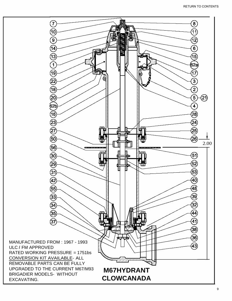
MANUFACTURED FROM : 1967 - 1993
ULC I FM APPROVED
RATED WORKING PRESSURE = 1751bs
CONVERSION KIT AVAILABLE- ALL
REMOVABLE PARTS CAN BE FULLY
UPGRADED TO THE CURRENT M67/M93
BRIGADIER MODELS- WITHOUT
EXCAVATING.
M67HYDRANT
CLOWCANADA
RETURN TO CONTENTS
9

McACIVITY M67 PARTS LIST
REF DESCRIPTION PRODUCT CODE
1 OPERATING HOUSING (now RETAINING GLAND W/
OP. NUT 63 & 64)
2 HOSE NOZZLE
2A NOZZLE ORING T8100214
3 HOSE CAP
4 HOUSING STEM ORING T8100207
6 HOUSING JOINT GASKET T8107782
7 OIL HOLE SCREW T8100131
8 DISCONTINUED SEE PART # 64 *OP NUT-SEE BELOW F8100872
9 OPERATING NUT ORING T8100210
10 BODY COVER SCREWS T8100152
11 BODY COVER O/L M8101508 O/R M8101509
12 NEEDLE BEARING R8103346
13 HOUSING CAP SCREWS T8100032
14 BODY CAP M8101507
15 BODY CAP ORING T8100221
16 UPPER BARREL 2H1P THREADED BODY DISCONTINUED
17 HOSE CAP GASKET T8107473
18 PUMPER CAP GASKET T8100243 / T810244
19 PUMPER CAP
20 PUMPER NOZZLE
20A PUMPER NOZZLE ORING T8100217
22 NOZZLE PIN (SAME AS BRIGADIER) F8100942
23 DISCONTINUED SEE PART #70 page 1 O/L A8104781
24 INTERSECTION BOLTS & NUT R8103201
25 SAFETY FLANGE SEGMENTS M8101510
26 INTERSECTION GASKET T8100240
27 SAFETY COUPLING M8101511
28 COUPLING BOLTS & NUT SET OF 2 R8103200
29 LOWER STEM 6'0" BURY M8101450
30 LOWER BARREL 6'0" BURY A8104110
31 DRIP VALVE ASSEMBLED F8100947
32 DRAIN HOLE LINER 1-13/32" T8100438 1-19/32"
T8105965
33 SEAT CASING ORING T8100220
34 LOWER SEAT ORING T8100218
34A UPPER SEAT ORING T8100219
35 MAIN VALVE RUBBER - BUNA T8100444
36 MAIN VALVE WASHER M8100932
37 COTTER PIN T8100139
38 MAIN VALVE ORING T8100206
39 DRIP VALVE FACING T8100443
40 DRIP VALVE FACING CLAMP T8100442
41 SEAT CASING **OBSOLETE** NOT OFFERED
42 MAIN VALVE SEAT F8100933
43 MAIN VALVE LOCKNUT F8100934
44 INLET BOOT (STATE JOINT TYPE)
48 HOLDING CLAMP SCREW T8100133
63 RETAINING GLAND M8104776
64 HYDRALUBE OPERATING NUT F8104760
70 UPPER OPERATING STEM A8104781
RETURN TO CONTENTS
10
RECEIVING & HANDLING /STORAGE
When receiving new fire hydrants, ensure the product received is correct and properly handled.
Check for damage during shipping
Check to ensure correct operating nuts & direction to open
Check to ensure nozzle thread configuration matches order (see photo page 13) Check to
ensure depth of bury & inlet type / size are correct
(see drawing page 7 & 14)
Check to ensure smooth & free operation with 16 – 18 turns before installation. Check
to ensure there are no loose bolts or nuts
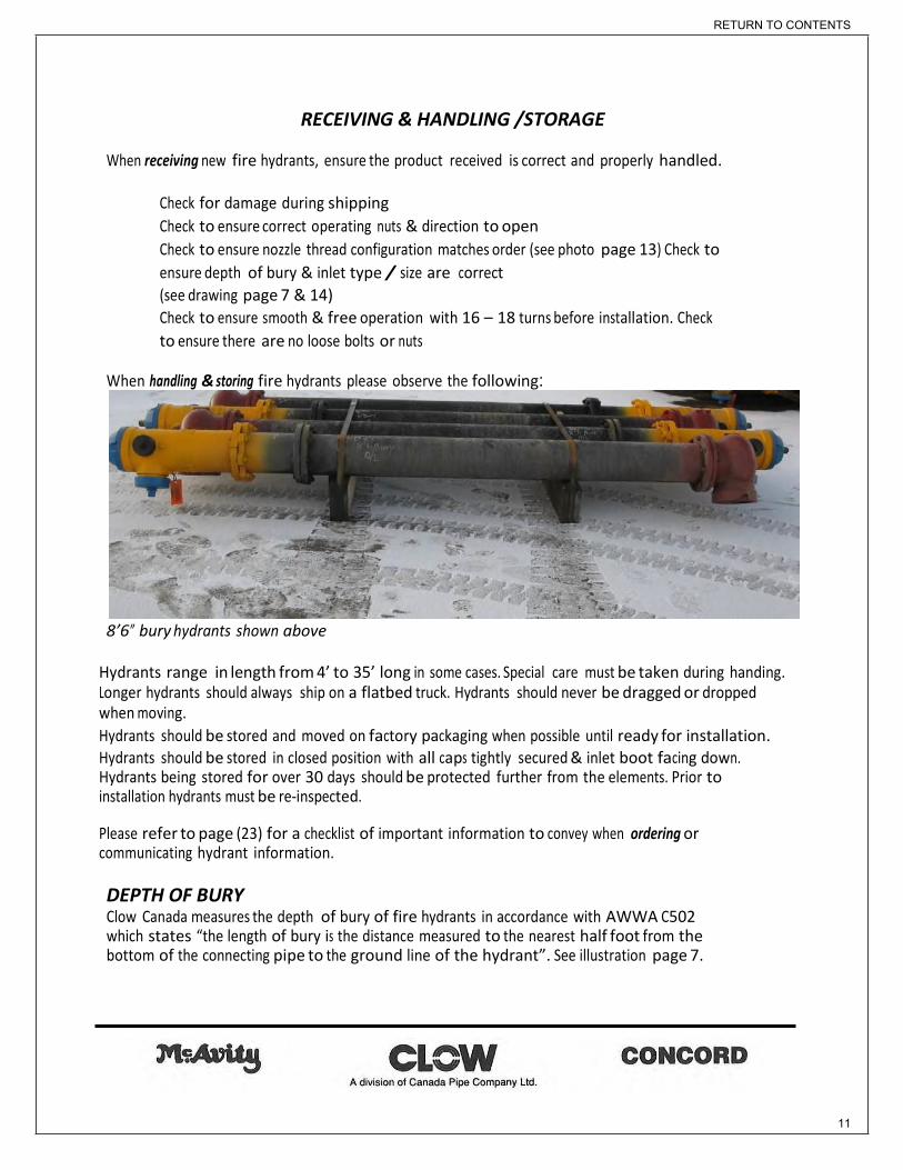
When handling & storing fire hydrants please observe the following:
8’6” bury hydrants shown above
Hydrants range in length from 4’ to 35’ long in some cases. Special care must be taken during handing. Longer hydrants should always ship on a flatbed truck. Hydrants should never be dragged or dropped when moving.
Hydrants should be stored and moved on factory packaging when possible until ready for installation. Hydrants should be stored in closed position with all caps tightly secured & inlet boot facing down. Hydrants being stored for over 30 days should be protected further from the elements. Prior to installation hydrants must be re-inspected. Please refer to page (23) for a checklist of important information to convey when ordering or communicating hydrant information. DEPTH OF BURY Clow Canada measures the depth of bury of fire hydrants in accordance with AWWA C502 which states “the length of bury is the distance measured to the nearest half foot from the bottom of the connecting pipe to the ground line of the hydrant”. See illustration page 7.
RETURN TO CONTENTS
11

FIRE HYDRANT IDENTIFICATION
Note: Identification should always start with the year of manufacture. This will be clearly cast on the hydrant body, along with other important data.
HERITAGE STYLE HYDRANT – shown on the left above has a nostalgic McAvity shape but uses all current standard parts from 1996 to present (see page 6). Octagonal body& bonnet, hose & pumper caps are the only difference between this & the standard round body hydrant (above center). This hydrant shares a common shape with the older McAvity M59 & M59M models but can be easily
identified by the 4 ground line flange segments (#25).
M67B BRIGADIER / M93B BRIGADIER - shown center are the current standard Clow hydrants. Both models share standard internal & external parts (see page 6). The difference is the (# 80) upper barrel only, where the model name is clearly cast. This hydrant was introduced into service in 1995
McAVITY M67 shown on the right (above) went into service in 1967. The parts breakdown is shown on Page 9 &10. Although there have been many improvements over the years the original hydrants parts are largely interchangeable with the current design. When a major overhaul is required, M67 hydrants never need to be removed from the system by excavating, as hydrant conversion kits are available to replace 85% of the hydrant from the surface. Contact your Clow Canada sales representative for details or visit www.clowcanada.com to view instructional videos on converting old hydrants to New.
RETURN TO CONTENTS
12

Pictures above showing Hose / pumper nozzle & matching cap. STAMPING LOCATIONS
PUMPER & HOSE NOZZLE CONNECTIONS
In addition to the hydrant model & year of manufacture, it is critical to properly identify the hose nozzle and pumper nozzle thread specification. Clow Canada identifies threads using a one or two letter code located on the hose and pumper Nozzle & caps. Nozzle & cap code must match to ensure Proper fit. These codes simplify the process purchasing replacement parts &complete hydrants.
STORZ PUMPER & HOSE NOZZLE CONNECTIONS Storz connections are increasingly popular & enable firefighting equipment to be attached to hydrants without the need for threaded connections. Lugs are used to lock the nozzle to the attaching equipment. Standard Storz pumper nozzles are available in 100mm (4”) & 125mm (5”) and Storz hose nozzles are available in 62.5mm (2.5”).
RETURN TO CONTENTS
13

COMMON OPERATING NUT SHAPES
COMMON INLET STYLES
Flanged inlets are available in cast or ductile iron with 150 or 250 lb drilling
RETURN TO CONTENTS
14

AUTOMATIC DRAINING & PLUGGED FIRE HYDRANTS
Fire hydrants are available self-draining or non-draining (plugged). When a hydrant is ordered plugged externally, two 3/8” NPT plugs are factory installed in the hydrant boot as shown below
2 plugs @ 180 degrees
Once the hydrant is buried this is a permanent condition.
CHANGING AUTOMATIC DRAINING HYDRANTS TO PLUGGED
Fire hydrants that have been installed as self-draining can be changed over to internally plugged, by adding a ¼” NPT plug to the (#42) main valve seat. See page 42 for complete step by step procedure.
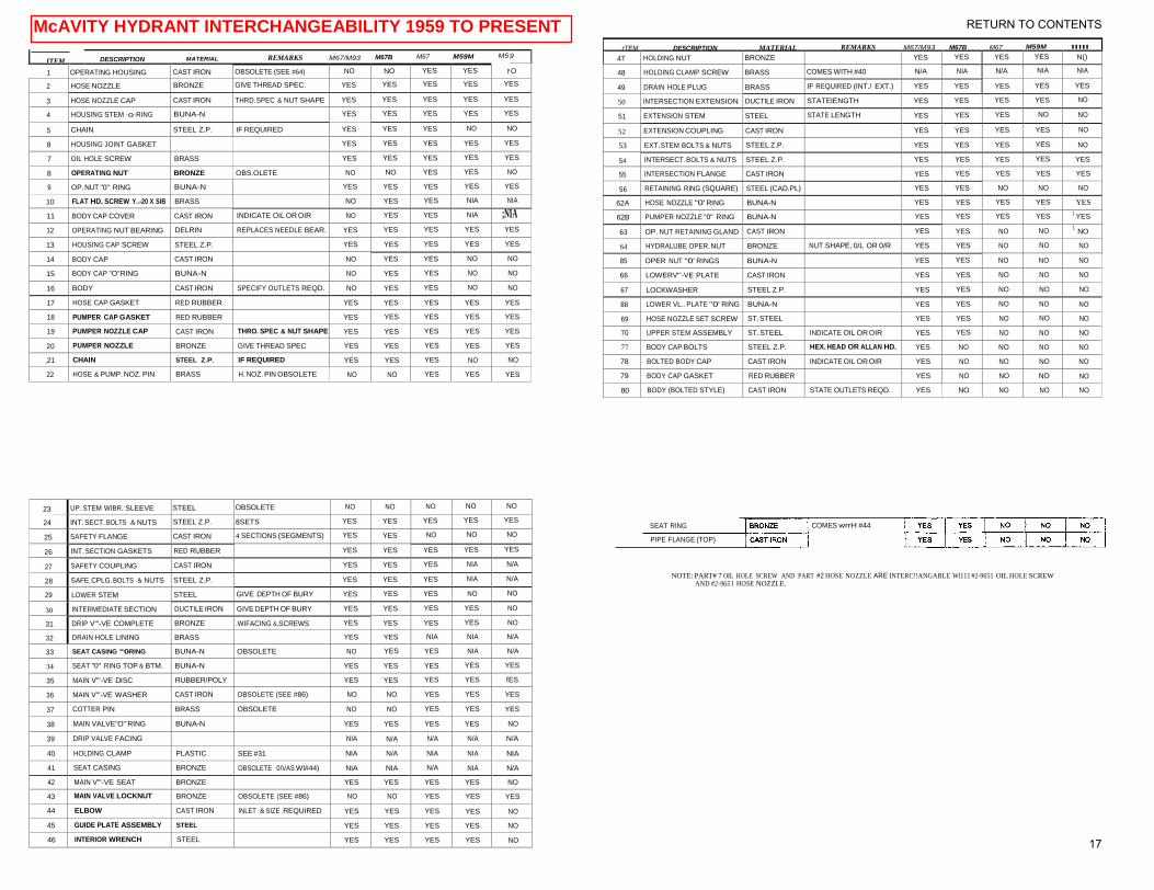
McAVITY HYDRANT INTERCHANGEABILTY Refer to the interchangeability table on page 17 to see which parts are common between different models of McAvity hydrants from 1959 up to the present day. The item numbers shown on the table are standardized across the latest M67 hydrant models (see drawings pages 8- 12). A yes across the row would indicate the part is common to all hydrant models shown at the top.
Below are pictures of the M59 & M59M models (in service from 1959 – 1967)
RETURN TO CONTENTS
15

F1g. M-59-M
McAVITY’S IMPROVED FIRE HYDRANT
Patented 1919
Adopted as Standard, August 1919
In the construction of our improved Fire Hydrant the most advanced methods of manufacturing and arrangement of detail have been adopted to meet the requirements of Water Works Superintendents in all parts of the country A special and exclusive feature is the patented operating nut, which is of great importance in Canada or other countries where the temperature drops below freezing. In our new Hydrant this operating nut is made of a design that permits the water to flow freely thereby preventing freezing. These Hydrants can be furnished wither either of our special design of seats. Bronze to Iron or the Bronze to Bronze principal which is very clearly explained in detail in our number 40 catalogue which we shall be pleased to send upon application. T. McAVITY & SONS, LIMITED
RETURN TO CONTENTS
16
MC AVITY HYDRANT INTERCHANGEABILITY CHART 1963 - PRESENT
47 HOLDING NUT BRONZE YES YES YES YES N()
48 HOLDING CLAMP SCREW BRASS COMES WITH #40 N/A NIA N/A NIA NIA
49 DRAIN HOLE PLUG BRASS IF REQUIRED (INT./ EXT.) YES YES YES YES YES
50 INTERSECTION EXTENSION DUCTILE IRON STATElENGTH YES YES YES YES NO
51 EXTENSION STEM STEEL STATE LENGTH YES YES YES NO NO
52 EXTENSION COUPLING CAST IRON YES YES YES YES NO
53 EXT. STEM BOLTS & NUTS STEEL Z.P. YES YES YES YES NO
54 INTERSECT. BOLTS & NUTS STEEL Z.P. YES YES YES YES YES
55 INTERSECTION FLANGE CAST IRON YES YES YES YES YES
56 RETAINING RING (SQUARE) STEEL (CAD.PL) YES YES NO NO NO
62A HOSE NOZZLE "0' RING BUNA-N YES YES YES YES YES
62B PUMPER NOZZLE "0" RING BUNA-N YES YES YES YES 1 YES
63 OP. NUT RETAINING GLAND CAST IRON YES YES NO NO 1
NO
64 HYDRALUBE OPER. NUT BRONZE NUT SHAPE, 0/L OR 0/R YES YES NO NO NO
85 OPER NUT "0' RINGS BUNA-N YES YES NO NO NO
66 LOWERV"'-VE PLATE CAST IRON YES YES NO NO NO
67 LOCKWASHER STEEL Z.P. YES YES NO NO NO
88 LOWER VL.. PLATE "0' RING BUNA-N YES YES NO NO NO
69 HOSE NOZZLE SET SCREW ST. STEEL YES YES NO NO NO
70 UPPER STEM ASSEMBLY ST. STEEL INDICATE OIL OR OIR YES YES NO NO NO
77 BODY CAP BOLTS STEEL Z.P. HEX. HEAD OR ALLAN HD. YES NO NO NO NO
78 BOLTED BODY CAP CAST IRON INDICATE OIL OR OIR YES NO NO NO NO
79 BODY CAP GASKET RED RUBBER YES NO NO NO NO
80 BODY (BOLTED STYLE) CAST IRON STATE OUTLETS REQD. YES NO NO NO NO
ITEM DESCRIPTION MATERIAL REMARKS M67/M93 M67B M67 M59M M5 9
1 OPERATING HOUSING CAST IRON OBSOLETE (SEE #64) NO NO YES YES N O
2 HOSE NOZZLE BRONZE GIVE THREAD SPEC. YES YES YES YES YES
3 HOSE NOZZLE CAP CAST IRON THRD.SPEC & NUT SHAPE YES YES YES YES YES
4 HOUSING STEM ·o·RING BUNA-N YES YES YES YES YES
5 CHAIN STEEL Z.P. IF REQUIRED YES YES YES NO NO
8 HOUSING JOINT GASKET YES YES YES YES YES
7 OIL HOLE SCREW BRASS YES YES YES YES YES
8 OPERATING NUT BRONZE OBS.OLETE NO NO YES YES NO
9 OP. NUT "0" RING BUNA-N YES YES YES YES YES
10 FLAT HD. SCREW Y..-20 X SIB BRASS NO YES YES NIA NIA
11 BODY CAP COVER CAST IRON INDICATE OIL OR OIR NO YES YES NIA ;NIA
12 OPERATING NUT BEARING DELRIN REPLACES NEEDLE BEAR. YES YES YES YES YES
13 HOUSING CAP SCREW STEEL Z.P. YES YES YES YES YES
14 BODY CAP CAST IRON NO YES YES NO NO
15 BODY CAP "O"RING BUNA-N NO YES YES NO NO
16 BODY CAST IRON SPECIFY OUTLETS REQD. NO YES YES NO NO
17 HOSE CAP GASKET RED RUBBER YES YES YES YES YES
18 PUMPER CAP GASKET RED RUBBER YES YES YES YES YES
19 PUMPER NOZZLE CAP CAST IRON THRO. SPEC & NUT SHAPE YES YES YES YES YES
20 PUMPER NOZZLE BRONZE GIVE THREAD SPEC YES YES YES YES YES
,21 CHAIN STEEL Z.P. IF REQUIRED YES YES YES NO NO
22 HOSE & PUMP. NOZ. PIN BRASS H. NOZ. PIN OBSOLETE NO NO YES YES YES
23
24
UP. STEM WIBR. SLEEVE STEEL OBSOLETE NO NO NO NO NO
INT. SECT. BOLTS & NUTS STEEL Z.P. 8SETS YES YES YES YES YES
25 SAFETY FLANGE CAST IRON 4 SECTIONS (SEGMENTS) YES YES NO NO NO
26 INT. SECTION GASKETS RED RUBBER YES YES YES YES YES
27 SAFETY COUPLING CAST IRON YES YES YES NIA N/A
28 SAFE.CPLG. BOLTS & NUTS STEEL Z.P. YES YES YES NIA N/A
29 LOWER STEM STEEL GIVE DEPTH OF BURY YES YES YES NO NO
30 INTERMEDIATE SECTION DUCTILE IRON GIVE DEPTH OF BURY YES YES YES YES NO
31 DRIP V"'-VE COMPLETE BRONZE .WIFACING &,SCREWS YES YES YES YES NO
32 DRAIN HOLE LINING BRASS YES YES NIA NIA N/A
33 SEAT CASING "0RING BUNA-N OBSOLETE NO YES YES NIA N/A
34 SEAT "0" RING TOP & BTM. BUNA-N YES YES YES YES YES
35 MAIN V"'-VE DISC RUBBER/POLY YES YES YES YES fES
36 MAIN V"'-VE WASHER CAST IRON OBSOLETE (SEE #86) NO NO YES YES YES
37 COTTER PIN BRASS OBSOLETE NO NO YES YES YES
38 MAIN VALVE"O" RING BUNA-N YES YES YES YES NO
39 DRIP VALVE FACING NIA N/A N/A N/A N/A
40 HOLDING CLAMP PLASTIC SEE #31 NIA N/A NIA NIA NIA
41 SEAT CASING BRONZE OBSOLETE 0/VAS Wl#44) NIA NIA N/A NIA N/A
42 MAIN V"'-VE SEAT BRONZE YES YES YES YES NO
43 MAIN VALVE LOCKNUT BRONZE OBSOLETE (SEE #86) NO NO YES YES YES
44 ELBOW CAST IRON INLET & SIZE REQUIRED YES YES YES YES NO
45 GUIDE PLATE ASSEMBLY STEEL YES YES YES YES NO
46 INTERIOR WRENCH STEEL YES YES YES YES NO
McAVITY HYDRANT INTERCHANGEABILITY 1959 TO PRESENT rTEM DE5CRIPTION MATERIAL REMARKS M67/M93 M67B M67 M59M
"'"
SEAT RING
PIPE FLANGE (TOP)
COMES wrrH #44
NOTE: PART# 7 OIL HOLE SCREW AND PART #2 HOSE NOZZLE ARE INTERC!!ANGABLE Wl111 #2-9651 OIL HOLE SCREW
AND #2-9651 HOSE NOZZLE.
RETURN TO CONTENTS
17

CHRONOLOGY OF CLOW HYDRANTS
Hydrant Model Shape Year 9651- #1 & 9651-#2 OCTAGONAL 1919/1960
9651- #1 & 9651- #2 ROUND 1919/1960
6431 #1 & #2 ROUND 1920/1960
9658 - 4" OCTAGONAL 1930/1960
9658 - 5" OCTAGONAL 1930/1960
965B - "O" RING STYLE OCTAGONAL 1930/1960
M-59 OCTAGONAL 1959/1963
M-59 ROUND 1959/1963
M-59M OCTAGONAL 1960/1967
M-59M ROUND 1960/1967
D63 DAIGLE 1960/1966
9635 W WALL TYPE 1960/1994
9635 F FLUSH TYPE 1960/1994
D80 DAIGLE 1965/1980
D67 CONCORD DAIGLE 1967/1975
M-67 McAVITY (WITH OPERATING NUT HOUSING) BULLET 1967/1994
M-67 McAVITY ON-LINE (WIOPERATING NUT HOUSING) BULLET 1967/1994
D67M CONCORD 1967/1994
500 DROLET 1975
D67M E TRINIDAD 1980
D67M METRO 1980
D67M-P PREMIER (HYDRALUBE) 1994/------
M-67 BRIGADIER THREADED CAP HYDRALUBE BULLET 1993/1996
M-67 BRIGADIER ON-LINE HYDRALUBE 1993/1996
9635 W WALL TYPE HYDRALUBE 1993/2010
9635 F FLUSH TYPE HYDRALUBE 1993/2010
M-67B HERITAGE HYDRALUBE ROUND& OCT. 1995/------
M-93B HERITAGE HYDRALUBE ROUND & OCT. 1995/------
M-67B BRIGADIER BOLTED CAP HYDRALUBE ROUND 1995/------
M-93B BRIGADIER BOLTED CAP HYDRALUBE ROUND 1995/------
CLOW CONCORD A division of Canada Pipe Company Ltd.
RETURN TO CONTENTS
18
SPECIAL HYDRANTS
MONITOR HYDRANT The Brigadier is available with monitor flange for use in industrial fire protection in pulp and paper mills, lumber yards or storage areas for inflammable materials. The hydrant's 3" (76mm) flanged outlet is faced and drilled to ANSI 125, suitable for connecting a long radius flanged elbow and standpipe for mounting a monitor nozzle. With the exception of the monitor elbow this hydrant uses ALL CURRENT STANDARD PARTS. It can also be supplied with:
The online chamber for mounting directly to the water main. An inline chamber for DEEP D.O.B. HYDRANTS 14’ + A class 250 ductile iron flanged inlet for high pressure applications
IN-LINE CHAMBER (DEEP D.O.B. HYDRANTS 14’ +) Clow Canada recommends all hydrants over 14’ Bury be supplied with an in-line chamber (around the 12’ mark) to make the hydrant more accessible & safe for maintenance. With depths of bury in the north regularly in the 15 – 20’ + range, hydrant maintenance becomes unsafe or impossible without the assistance of heavy equipment. The inline chamber corrects this issue by moving the main valve components up to the usual bury depth and is available for all McAvity hydrants.
FLANGED ELBOWS – M67B BRIGADIER / M93B BRIGADIER are available with ASTM A536 ductile iron flanged elbows in class 125 and 250 for higher pressure applications.
ON-LINE HYDRANT - In many northern communities & on industrial sites hydrants must be attached directly to the water main by way of a tee. Clow supplies the M67B BRIGADIER / M93B BRIGADIER with either a 6” or 8” ANSI B16.1flanged vertical chamber to facilitate this. With the exception of the online chamber this hydrant uses ALL CURRENT STANDARD PARTS. It can also be supplied with an inline chamber for DEEP D.O.B. HYDRANTS 14’ +
HERITAGE STYLE HYDRANT – shown on page 12 has a nostalgic McAvity shape but uses all current standard parts from 1995 to present. Octagonal body& bonnet, hose & pumper caps are the only difference between this & the standard round body M67Bhydrant. This hydrant shares a common shape with the older McAvity M59 & M59M models but can be easily identified by the 4 ground line flange segments (#25).
HYDRANT INSULATING KIT - When hydrants are buried in the frost line, a thermal break must be installed below the frost line, at the hydrant inlet. The flange isolation kit stops thermal conductivity through the hydrant into the piping system. This option is available on all hydrants.
RETURN TO CONTENTS
19

CLOW CANADA WITH MONITOR
250 PSI FM APPROVED
3
17
69
2
62a
77
7
79 78
80 9
62b
20
61 19
12
57 64
58
59 65
22 4 24
26 6
56 63
82 13
25 70
55
26
DESCRIPTION DESCRIPTION
2 HOSE NOZZLE 42 MAIN VALVE SEAT
3 HOSE NOZZLE CAP 44* ELBOW ( M.J., FLGD, P.O. & ON-LINE)
4 HOUSING STEM "O" RINGS 48 HOLDING CLAMP SCREW
5 HOSE CAP CHAIN & "S" HOOK 49 DRAIN HOLE PLUG
6 HOUSING JOINT GASKET 49a EXTERNAL DRAIN HOLE PLUGS
7 OIL HOLE SCREW 50 INTERSECTION EXTENSION
9 OPERATING NUT "O" RING 55 PIPE FLANGE (BOTTOM)
12 OPERATING NUT BEARING 56 RETAINING RING (SQUARE)
13 CAP SCREW 1/2" x 1 1/4"(RET. GLD. BOLTS) 57 MONITOR BOLTS & NUTS (5/8"x2 3/4")
17 HOSE CAP GASKET 58 MONITOR ELBOW
19 PUMPER CAP 59 MONITOR GASKET
20 PUMPER NOZZLE 61 PUMPER CAP GASKET
21 PUMPER CAP CHAIN & S HOOK 62a HOSE NOZZLE "O" RING
22 PUMPER NOZZLE PIN 62b PUMPER NOZZLE "O" RING
24 INTERSECTION BOLTS & NUTS 63 OPERATING NUT RETAINING GLAND
25 SAFETY FLANGE SEGMENTS 64 HYDRALUBE OPERATING NUT
26 INTERSECTION GASKET 65 RETAINING GLAND "O" RINGS
27 SAFETY COUPLING 66 LOWER VALVE PLATE
28 SAFETY COUPLING BOLT & NUT (3/8"x3") 67 MAIN VALVE LOCKWASHER
29 LOWER OPERATING STEM 68 LOWER VALVE PLATE "O" RING
30 INTERMEDIATE SECTION 69 HOSE NOZZLE SET SCREW
31 DRIP VALVE 70 UPPER OPERATING STEM
32* DRAIN HOLE LINING 77 BODY CAP ALLEN SCREWS OR HEX BOLTS
34a MAIN VALVE SEAT "O" RING (UPPER) 78 BODY CAP
34 MAIN VALVE SEAT "O" RING (LOWER)) 79 BODY CAP GASKET
35 MAIN VALVE DISC 80 BODY
38 MAIN VALVE "O" RING 81* SEAT RING
39 DRIP VALVE RUBBER 82 PIPE FLANGE (TOP)
40 HOLDING CLAMP 83 SAFETY COUPLING CLEVIS BOLT & PIN
44,32 & 81
97 27
49a
28
83
40
39
31
48
38
42
49
34a
34
35
67
66
68
MADE IN CANADA www.clowcanada.com
Click Here For
Hydrant Specs!
RETURN TO CONTENTS
20

MADE IN CANADA
CLOW CANADA IN-LINE HYDRANT
250 PSI FM APPROVED
7
77
78
9
79 12
62b 20
61 19
80
62a 64
2
69 65
17
3 4
6
63
22
13 26
25
56
M67B IN-LINE HYDRANT STANDARD PARTS
70
82
30
28
55
26 27
83 24
Ref No
2
3
4
5
DESCRIPTION
HOSE NOZZLE HOSE
NOZZLE CAP HOUSING
STEM "O" RINGS
HOSE CAP CHAIN & "S" HOOK
Ref No
42
44*
48
49
DESCRIPTION
MAIN VALVE SEAT
NON-DRAIN ELBOW (STATE INLET REQUIRED)
HOLDING CLAMP SCREW
DRAIN HOLE PLUG
81 29
32
86 6 HOUSING JOINT GASKET
7 OIL HOLE SCREW
49a 3/8" PIPE PLUGS EXTERNAL
50 EXTENSION PIECE
9
12
13
17
19
20
21
22
24
25
26
27
28
29
30
31
32*
34a
34
35
38
39
40
OPERATING NUT "O" RING
OPERATING NUT BEARING
CAP SCREW (1/2" X 1 1/4")
HOSE CAP GASKET
PUMPER NOZZLE CAP
PUMPER NOZZLE
PUMPER CAP CHAIN & "S" HOOK
PUMPER NOZZLE PIN
INTERSECTION BOLTS & NUTS
SAFETY FLANGE (SEGMENTS)
INTERSECTION GASKET
SAFETY COUPLING
SAFETY COUPLING BOLT & NUT (3/8" X 3
OPERATING STEM LOWER
INTERMEDIATE SECTION
DRIP VALVE
DRAIN HOLE LINING C/W CHAMBER
SEAT "O" RING (TOP)
SEAT "O" RING (BOTTOM)
MAIN VALVE DISC
MAIN VALVE "O" RING
DRIP VALVE FACING
HOLDING CLAMP
55
56
61
62a
62b
63
64
65
66
67
68
69
70
77
78
79
80
81*
82
83
86
87
88
PIPE FLANGE (BOTTOM)
RETAINING RING (SQUARE)
PUMPER CAP GASKET
HOSE NOZZLE "O" RING
PUMPER NOZZLE "O" RING
OPERATING NUT RETAINING CLAND
HYDRALUBE OPERATING NUT
RETAINING CLAND "O" RINGS
LOWER VALVE PLATE
MAIN VALVE LOCKWASHER
LOWER VALVE PLATE "O" RING
HOSE NOZZLE SET SCREW (1/4" x 3/4")
UPPER OPERATING STEM
BODY CAP HEX BOLTS or ALLAN SCREWS
BODY CAP
BODY CAP GASKET
BODY
SEAT RING C/W CHAMBER
PIPE FLANGE TOP
SAFETY COUPLING CLEVIS BOLT & PIN
IN-LINE CHAMBER
ON-LINE SPIDER
3/8" x 1 1/4" BOLT
88
50
40
39
48 49
49a
44
87
31
42
34a
34
38
35
67
66
68
www.clowcanada.com
RETURN TO CONTENTS
21

CLOW CANADA 6" ON-LINE HYDRANT
250 PSI FM APPROVED
62a 2
69 17
3
77
79 78
62b 20
61
19
7
80 9
12
22 64
24
65
4
6
63
25
26 13
56
82 70
30
55
56 28
26
32
91
M67B 6" ON-LINE HYDRANT STANDARD PARTS
83
81 27
91 29
24 88 Ref No
2
3
4
5
DESCRIPTION
HOSE NOZZLE HOSE
NOZZLE CAP HOUSING
STEM "O" RINGS
HOSE CAP CHAIN & "S" HOOK
Ref No
40
42
48
49
DESCRIPTION
HOLDING CLAMP MAIN
VALVE SEAT HOLDING
CLAMP SCREW DRAIN
HOLE PLUG
48 49a
40
87 6 HOUSING JOINT GASKET 49a 3/8" PIPE PLUGS EXTERNAL 39 7
9
12
13
17
19
20
21
22
24
25
26
27
28
29
30
31
32*
34a
34
35
38
39
OIL HOLE SCREW
OPERATING NUT "O" RING
OPERATING NUT BEARING
CAP SCREW (1/2" X 1 1/4")
HOSE CAP GASKET
PUMPER NOZZLE CAP
PUMPER NOZZLE
PUMPER CAP CHAIN & "S" HOOK
PUMPER NOZZLE PIN
INTERSECTION BOLTS & NUTS
SAFETY FLANGE (SEGMENTS)
INTERSECTION GASKET
SAFETY COUPLING
SAFETY COUPLING BOLT & NUT (3/8" X 3")
OPERATING STEM LOWER
INTERMEDIATE SECTION
DRIP VALVE
DRAIN HOLE LINING C/W CHAMBER
SEAT "O" RING (TOP)
SEAT "O" RING (BOTTOM)
MAIN VALVE DISC
MAIN VALVE "O" RING
DRIP VALVE FACING
55
56
61
62a
62b
63
64
65
66
67
68
69
70
77
78
79
80
81*
82
83
87
88
91
PIPE FLANGE (BOTTOM)
RETAINING RING (SQUARE)
PUMPER CAP GASKET
HOSE NOZZLE "O" RING
PUMPER NOZZLE "O" RING
OPERATING NUT RETAINING CLAND
HYDRALUBE OPERATING NUT
RETAINING GLAND "O" RINGS
LOWER VALVE PLATE
MAIN VALVE LOCKWASHER
LOWER VALVE PLATE "O" RING
HOSE NOZZLE SET SCREW (1/4" x 3/4")
UPPER OPERATING STEM
BODY CAP HEX BOLTS or ALLAN SCREWS
BODY CAP
BODY CAP GASKET
BODY
SEAT RING C/W CHAMBER
PIPE FLANGE TOP
SAFETY COUPLING CLEVIS BOLT & PIN
ON-LINE SPIDER
3/8" x 1 1/4" BOLT
6" ON-LINE CHAMBER
38
49
31
42
34a
34
35
67
66
68
MADE IN CANADA www.clowcanada.
RETURN TO CONTENTS
22

Fire Hydrant Ordering Specifications Checklist
`
RETURN TO CONTENTS
23

INSTALLATION & TESTING
**WARNING**
FIRE HYDRANTS SHOULD BE OPERATED, MAINTAINED & REPAIRED BY TRAINED
AUTHORIZED PERSONS ONLY!
BEFORE ATEMPTING ANY INSTALLATION, REPAIRS OR MODIFICATIONS TO FIRE
HYDRANTS CONNECTING WATERLINES MUST BE ISOLATED, DRAINED AND
DEPRESSURIZED.
FAILURE TO OBSERVE BASIC SAFTEY GUIDELINES MAY RESULT IN SERIOUS
INJURY.
1) Complete a receiving inspection as outlined on (page 11)
2) Ensure all dirt & debris is removed from inside the hydrant.
3) Local codes and standards should be followed for guideines on installing the hydrant in relation to curbs, sidewalks and roads.
4) The hydrant should be installed with adequate clearance for operation, and attaching hoses & other machinery.
5) Hydrants should be installed as plumb as possible. 6) Consult AWWA Manual M17 (INSTALLATION FIELD TESTING & MAINTENANCE OF FIRE
HYDRANTS) for a comprehensive listing of procedures, tests and technical data relating to AWWA C502 hydrants.
TOOLS REQUIRED FOR MAINTENANCE / REPAIRS
Clow hydrant operating wrench – fits all nut sizes on any fire hydrant.
RETURN TO CONTENTS
24

Clow Seat Removal Tool & Guide Plate for use on all McAvity hydrants dating back to 1967. (M67 /
M67B BRIGADIER / M93B BRIGADIER) check with sales for compatibility with other Clow Canada
Hydrants.
The Holding nut is for use on all CLOW /McAvity hydrants dating back to 1967. The Holding nut must be
ordered specifically for either LEFT or RIGHT hand open hydrants.
Clow’s Body Cap Wrench is for use on McAvity M67 fire hydrants with the threaded on bonnet.
RETURN TO CONTENTS
25

Clow’s standard Pumper Nozzle Removal Tool is
available in Small, Medium, Large sizes
The size required depends on the 2 letter code
stamped on the pumper nozzle.
LARGE MEDIUM SMALL VH NF OH EG JF AH CH
PF SF KF FE GE DH GH XE YE HE KE LE BF BE ND OD ME OE PE DE AJ PD SD CD ED FD WD YD GD HD KD VD DG EF VE
MF AD BD
Clow’s standard Hose Nozzle Removal Tool is available in
Small & Large sizes.
The small size fits the X, Y, & Z, hose nozzle. The
large size fits all other letter codes.
A B C D E F G X Y Z AA BB CC JJ
LL NN SS TT VV YY ZZ
Clow’s STORZ Pumper Nozzle Removal Tool is available for
100mm (4”) and 125mm (5”) STORZ pumper sizes. This tool is designed for use on Clow hydrants with STORZ
pumper connections.
RETURN TO CONTENTS
26
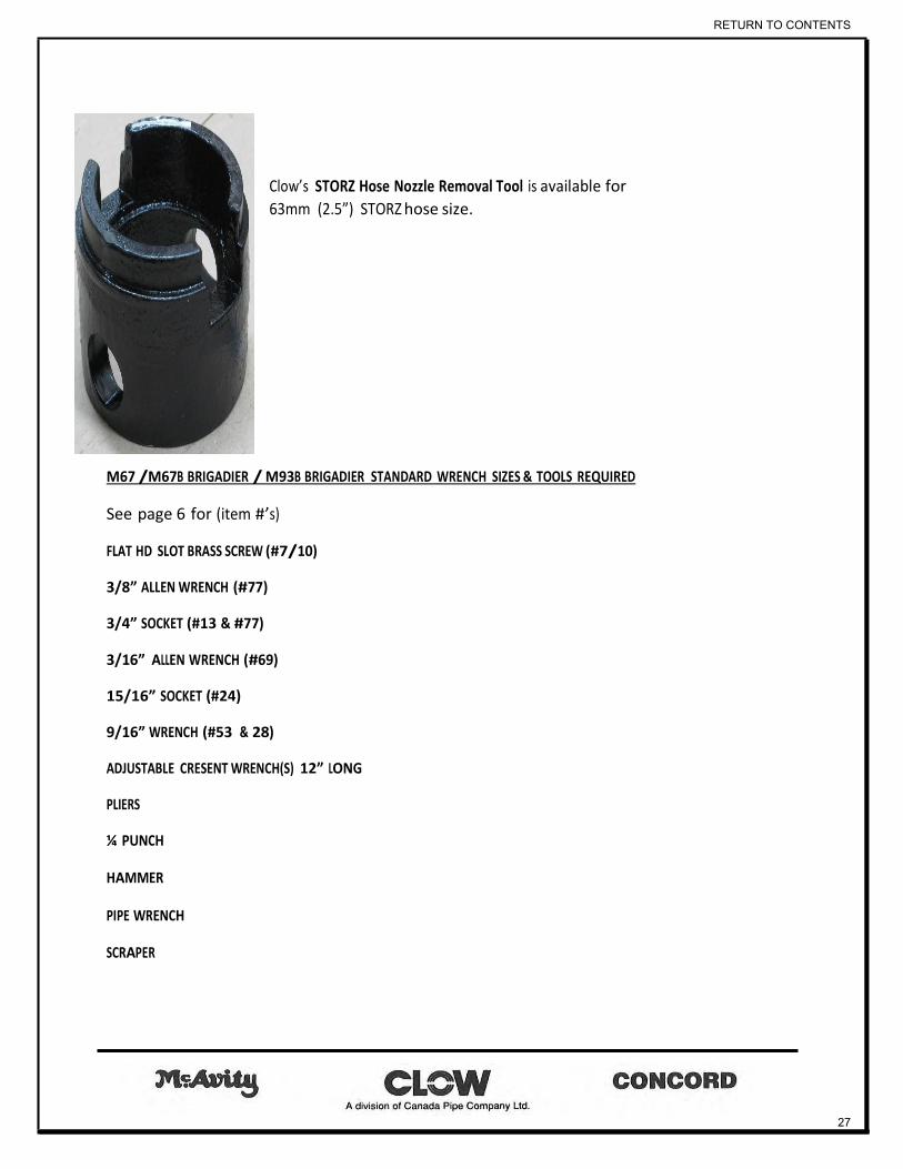
Clow’s STORZ Hose Nozzle Removal Tool is available for
63mm (2.5”) STORZ hose size.
M67 /M67B BRIGADIER / M93B BRIGADIER STANDARD WRENCH SIZES & TOOLS REQUIRED
See page 6 for (item #’s)
FLAT HD SLOT BRASS SCREW (#7/10)
3/8” ALLEN WRENCH (#77)
3/4” SOCKET (#13 & #77)
3/16” ALLEN WRENCH (#69)
15/16” SOCKET (#24)
9/16” WRENCH (#53 & 28)
ADJUSTABLE CRESENT WRENCH(S) 12” LONG
PLIERS
¼ PUNCH
HAMMER
PIPE WRENCH
SCRAPER
RETURN TO CONTENTS
27

PRE ASSEMBLED FIRE HYDRANT REPAIR KITS
HYDRA-LUBE OPERATING NUT & UPPER STEM ASSEMBLY / CONVERSION KIT
This kit replaces all internal above grade components It takes older hydrants (1967 – 1994) and brings their above Grade working components up to current standards. Consists of part numbers: 6/7/9/12/13/15/26/28/63/64/65/70 (From illustration page 6)
INLET COMPLETE Consists of part numbers: 32/41/44 (from illustration page 6) The 90 degree hydrant inlet is available with: class 125 flange / Tyton / Mechanical joint/ Class 250 flanged end connections in ductile or cast iron.
DRIP VALVE & SEAT COMPLETE Consists of part numbers: 31/34&34a/38/39/40/42/48 (from illustration page 33) Replaces all parts of the main valve assembly
LOWER STEM COMPLETE WITH DRIP VALVE & SEAT Consists of part numbers: 27/28/29/31/34&34a/35/38/39/40/42/48/ 66/67/68/70 (from illustration page 32) Replaces all removable below grade parts
RETURN TO CONTENTS
28
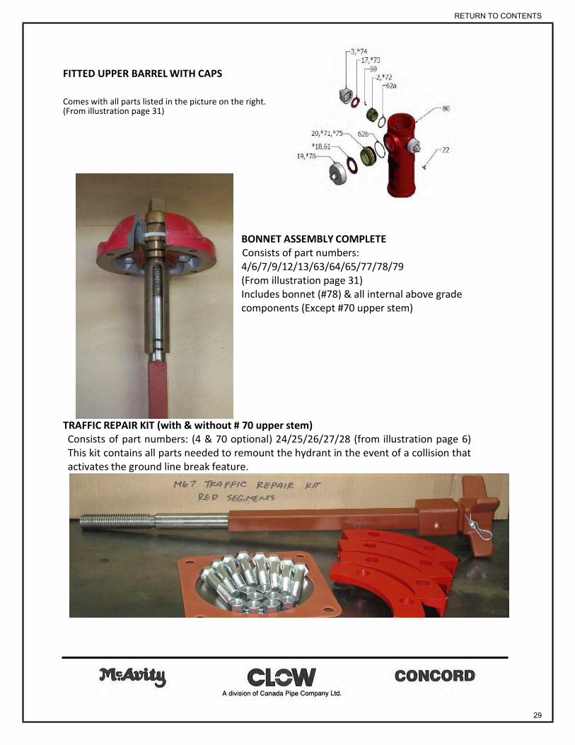
FITTED UPPER BARREL WITH CAPS Comes with all parts listed in the picture on the right. (From illustration page 31)
BONNET ASSEMBLY COMPLETE Consists of part numbers: 4/6/7/9/12/13/63/64/65/77/78/79 (From illustration page 31) Includes bonnet (#78) & all internal above grade components (Except #70 upper stem)
TRAFFIC REPAIR KIT (with & without # 70 upper stem) Consists of part numbers: (4 & 70 optional) 24/25/26/27/28 (from illustration page 6) This kit contains all parts needed to remount the hydrant in the event of a collision that activates the ground line break feature.
RETURN TO CONTENTS
29

UPPER BODY COMPLETE The FITTED UPPER BARREL WITH CAPS / BONNET ASSEMBLY COMPLETE / TRAFFIC REPAIR KIT (with # 70 upper stem) = UPPER BODY COMPLETE This replace all the assembled above grade components. See page 31.
CONVERSION KITS
The Complete Upper Body & Stem Conversion Kit is required to upgrade any old Clow
(McAvity, Concord) compression style hydrant, to its equivalent new model.
This is done without excavating! The only remaining components are the old
hydrant elbow & riser barrel.
Below is a listing of available conversions:
#2 9651 to M67 BRIGADIER
M59 to M67 BRIGADIER
M59M to M67 BRIGADIER
C-61-A to M67 HERITAGE
D67 to D67M PREMIER
D67M
to
D67M PREMIER
D63 to D67M PREMIER
CANRON CT to D67M PREMIER
DURITE H-64 to D67M PREMIER
DURITE H-67 to D67M PREMIER
#1 – 9651 to #1 – 9651 HERITAGE
RETURN TO CONTENTS
30

CLOW CANADA BODY COMPLETE
WITH UPPER STEM
3
17 77
69
2 79 78
62a 80
62b
20
61
19
12
7
9
22 64
65
4
24 6
25 63
13
26
70
2 HOSE NOZZLE 25 SAFETY FLANGE SEGMENTS
3 HOSE CAP 26 INTERSECTION GASKET
4 HOUSING STEM O RINGS 61 PUMPER CAP GASKET
6 HOUSING JOINT GASKET 62a HOSE NOZZLE O RING
7 OIL HOLE SCREW 62b PUMPER NOZZLE O RING
9 OPERATING NUT O RING 63 OPERATING NUT RETAINING GLAND 83
12 OPERATING NUT BEARING 64 OPERATING NUT 28
13 RETAINING GLAND HEX BOLTS 65 OP. NUT RETAINING GLAND O RINGS
17 HOESE CAP GASKET 69 HOSE NOZZLE SET SCREW 27
19 PUMPER CAP 70 UPPER STEM
20 PUMPER NOZZLE 77 BODY CAP HEX BOLTS
22 PUMPER NOZZLE PIN 78 BODY CAP
24 INTERSECTION BOLTS & NUTS 79 BODY CAP GASKET
RETURN TO CONTENTS
31
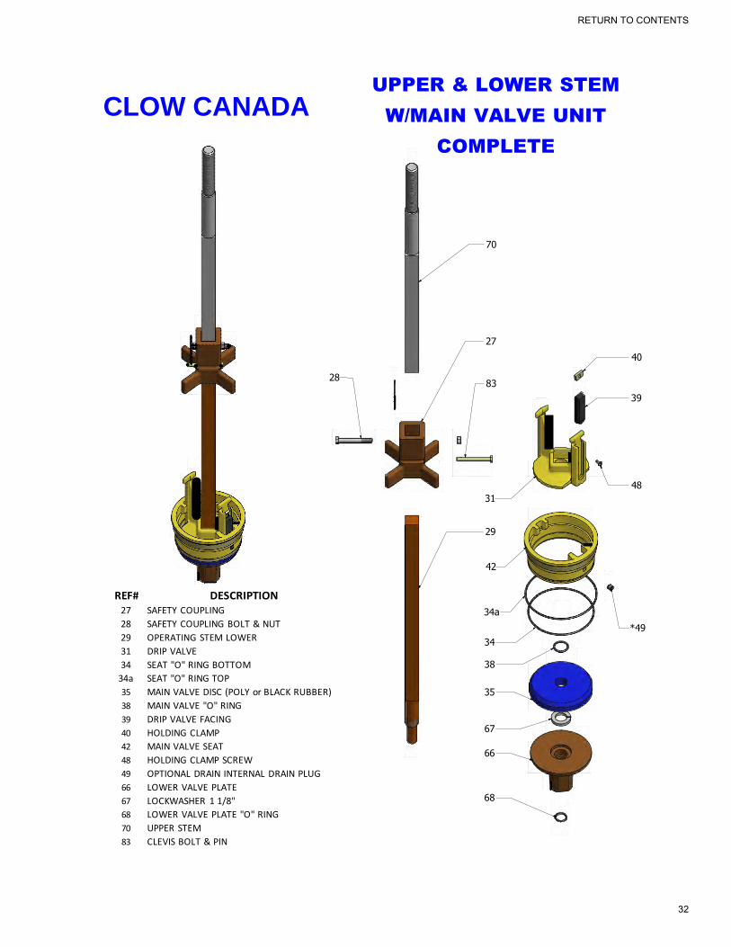
CLOW CANADA UPPER & LOWER STEM
W/MAIN VALVE UNIT
COMPLETE
70
27
40
28 83
39
48
31
29
42
REF# DESCRIPTION
27 SAFETY COUPLING
28 SAFETY COUPLING BOLT & NUT
29 OPERATING STEM LOWER
31 DRIP VALVE
34 SEAT "O" RING BOTTOM
34a SEAT "O" RING TOP
35 MAIN VALVE DISC (POLY or BLACK RUBBER)
38 MAIN VALVE "O" RING
39 DRIP VALVE FACING
40 HOLDING CLAMP
42 MAIN VALVE SEAT
48 HOLDING CLAMP SCREW
49 OPTIONAL DRAIN INTERNAL DRAIN PLUG
66 LOWER VALVE PLATE
67 LOCKWASHER 1 1/8"
68 LOWER VALVE PLATE "O" RING
70 UPPER STEM
83 CLEVIS BOLT & PIN
34a
34 38
35 67
66
68
*49
RETURN TO CONTENTS
32

INSTRUCTIONS FOR EXTENDING THE McAVITY M67B I BRIGADIER HYDRANT
Components List
1 - #50 Extension Barrel with Threaded Flange
1 - #51 Extension Stem
2 - #26 Intersection Gaskets
1 - #52 Alignment Extension Coupling
1 - #82 Pipe Flange (Top)
1 - #56 Retaining Ring
8 - Threaded Flange Bolts & Nuts
2 - #28 Coupling Bolts & Nuts
For Safety’s sake. please ensure that the water supply is turned off.
Step 1: Disassemble the upper barrel (Hydrant Body).
a) If extending a hydrant with a threaded body cap. unscrew body cap cover screws (2) #10, and remove body cap cover #11. Unscrew the body cap #14 anti-clockwise and unscrew the Hydralube nut #64 from the upper stem. Remove body cap assembly consisting of body cap, retaining gland and operating nut.
If extending a hydrant with bolt down body cap. remove the body cap bolts Unscrew Hydralube nut #64 to remove
the body cap #78.
b) Remove bolts #24 from safety flange segments #25 and pipe flange (top) #82.
c) Lift the body #16 I #80 off the intermediate section #30 The upper stem #231#70 is now protruding.
d) Remove the safety coupling #27 from the lower stem #29 only. leaving the upper stem attached to the coupling.
Step 2: Install the Ex tension
a) Assemble extension stem #51 to extension stem alignment coupling #52 and connect to lower stem #29.
b) Replace gasket #26 affixed to intermediate section #30. Lower the extension barrel #50. w1th threaded flange facing
the bottom, over the extension stem #51. (check threaded flange to ensure barrel portion is protruding). Align with
gasket bolt holes and intermediate flange hole.
c) Install threaded flange bolts & nuts and torque evenly between flanges to minimum 77ft. lbs. of torque.
Step 3: Re-assemble the upper barrel (Hydrant Body)
a) Re-attach upper stem #23 I #70 to extension stem #51. Securely tighten bolts & nuts (or clevis bolt & pin)
b) Place gasket #26 on to extension barrel #50. Replace body #16/ #80 on to extension barrel #50 and orient body
to your requirements. Check if gasket is still centered.
c) Assemble safety flange segments #25. Install and torque bolt & nuts evenly between flanges to a
minimum of 77 ft/lbs. torque.
d) Check interior of operating nut for 0-ring damage. Replace if necessary. Liberally lubricate 0-rings and threads,
align cap assembly and slip over operating stem #23/ #70.
e) For bolt down body caps, spin body cap assembly downwards until body cap meets hydrant body.
Align bolt holes and screw in body cap bolts.
For threaded body caps. spin body cap assembly downwards and then tighten clockwise to a minimum of 60ft.
lbs. torque using the body cap wrench. RE-assemble body cap cover #11 with cover screws #10.
RETURN TO CONTENTS
33

**WARNING**
REGULAR MAINTENANCE PROCEDURES
**Warning** FIRE HYDRANTS SHOULD BE OPERATED, MAINTAINED & REPAIRED BY TRAINED AUTHORIZED PERSONS ONLY! BEFORE ATEMPTING ANY INSTALLATION, REPAIRS OR MODIFICATIONS TO FIRE HYDRANTS CONNECTING WATERLINES MUST BE ISOLATED, DRAINED AND DEPRESSURIZED. FAILURE TO OBSERVE BASIC SAFTEY GUIDELINES MAY RESULT IN SERIOUS INJURY.
Hydrant Maintenance V ideos http://www.clowcanada.com
The following maintenance procedures have been posted on the Clow Canada web site, AS VIDEOS for a complete visual aid for our end users. The text in the manual is synchronized with the online videos that can be found at the link below.
http://www.clowcanada.com/english/Videos.html Hydrant maintenance Hydra Lube operating nut conversion video Complete Upper Body & Stem Conversion video Hydrant Extension Video Hydrant Plugging Video For further assistance please contact us.
LUBRICATION 1. Hydrants should be able to be operated with one arm and an 18” long hydrant operating wrench
(dry or under pressure). If this is not the case, the hydrant probably needs lubrication at the operating nut level.
2. Remove the lubrication screw (#7).
3. Lubricate with a food grade lubricant (good to -40 deg. C) after ensuring that the hydrant is in the
closed position to prevent over filling.
4. Replace the lubrication screw.
HYDRANT MAINTENANCE 1) As part of a regular maintenance program Clow Canada recommends hydrants be inspected
/serviced & operated on a bi annual basis. Once in the spring & once in the fall. For more details Consult AWWA Manual M17 (INSTALLATION FIELD TESTING & MAINTENANCE OF FIRE HYDRANTS).
RETURN TO CONTENTS
34

wet, or under pressure
2) Before proceeding with hydrant maintenance, perform a visual inspection of the area ensuring proper height and good access to the hydrant.
3) Operate the hydrant.
4) Fully open and close the hydrant. Check for easy operation verifying that there are 16 to 18 turns to the fully open position.
5) Make sure the upper body and caps are in good condition.
6) Remove cap and attach hose or flow diffuser.
7) Flow the hydrant to flush debris.
8) In the case of this video, the water has been turned off at the main valve. The water flow should
be consistent and not sporadic, which would indicate a blockage in the hydrant.
9) Now close the hydrant.
10) Check the drain feature. Place the palm of your hand over the open hose nozzle. There should
be a slight vacuum.
11) Operate the hydrant dry, or with no pressure.
12) Close the secondary valve to shut off the water supply.
13) Open the hydrant fully to release the bonnet assembly& any residual water pressure.
14) Make sure there is easy operation and no water flow.
M67B & M93B BRIGADIER
15) Remove the bonnet bolts (#77).
16) Remove the bonnet assembly by fully opening (#64) operating nut to release (#70) upper stem.
17) Remove gasket (#79).
McAvity M67 (screw on bonnet)
18) Remove weather cap screws (#10).
19) Remove lubrication screw (#7).
20) Now remove the cover.
21) Next remove the bonnet, noting the sequence of parts for reassembly.
RETURN TO CONTENTS
35

22) Check and replace the O-ring (#15).
23) Insert the interior wrench.
24) Thread the Holding Nut onto the upper stem.
25) Using a hydrant operating wrench draw hydrant closed, by threading holding nut fully on upper
stem. This will prevent damage to the drip valve.
26) Insert torque bar & Unthread the Main Valve Seat - turn counter clockwise.
26) Remove the Interior Wrench and Holding Nut.
27) Now lift out the stem assembly safely. Rest the spider coupling on the top of the hydrant and re-
grip.
28) Remove the main valve seat O-rings.
29) Disassemble the main valve (see illustration page 33).
30) Remove and replace the main valve O-ring #38
31) Replace the main valve disc #44.
32) Replace the main valve seat O-rings #34 UPPER & LOWER.
33) Reassemble the main valve.
34) Lubricate O-rings & complete seat
with generous amount of grease to aid re- assembly. Remember to use food grade grease.
35) Reinsert the stem assembly.
36) Thread in the main valve seat by
turning clockwise.
37) Insert the interior wrench.
38) Thread the holding nut onto the
upper stem.
39) Draw the hydrant to the closed position to prevent damage to the drip lever.
RETURN TO CONTENTS
36
40) Tighten the main valve seat.
41) Remove interior wrench and holding nut.
42) Reinstall the bonnet assembly.
43) Reattach the weather cap.
44) Remove the lubrication screw.
45) Insert the grease nipple.
46) Lubricate with a food grade lubricant (good to -40 deg. C) ensuring that the hydrant is in the
closed position to prevent over filling.
47) Remove the grease nipple.
48) Replace the lubrication screw.
49) Reinstall the hose and pumper caps.
50) Open the secondary valve.
51) Now open the hydrant and check for leaks.
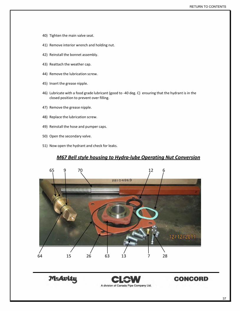
M67 Bell style housing to Hydra-lube Operating Nut Conversion
65 9 70 12 6
64 15 26 63 13 7 28
RETURN TO CONTENTS
37
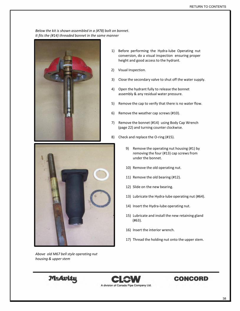
Below the kit is shown assembled in a (#78) bolt on bonnet. It fits the (#14) threaded bonnet in the same manner
1) Before performing the Hydra-lube Operating nut conversion, do a visual inspection ensuring proper height and good access to the hydrant.
2) Visual Inspection.
3) Close the secondary valve to shut off the water supply.
4) Open the hydrant fully to release the bonnet
assembly & any residual water pressure.
5) Remove the cap to verify that there is no water flow.
6) Remove the weather cap screws (#10).
7) Remove the bonnet (#14) using Body Cap Wrench
(page 22) and turning counter clockwise.
8) Check and replace the O-ring (#15).
9) Remove the operating nut housing (#1) by
removing the four (#13) cap screws from under the bonnet.
10) Remove the old operating nut.
11) Remove the old bearing (#12).
12) Slide on the new bearing.
13) Lubricate the Hydra-lube operating nut (#64).
14) Insert the Hydra-lube operating nut.
15) Lubricate and install the new retaining gland
(#63).
16) Insert the interior wrench.
17) Thread the holding nut onto the upper stem.
Above old M67 bell style operating nut housing & upper stem
RETURN TO CONTENTS
38

18) Using a hydrant operating wrench draw hydrant closed by threading holding nut fully on upper
stem. This will prevent damage to the drip valve.
19) Insert torque bar & unthread the main valve seat by turning counter clockwise.
20) Remove the interior wrench and holding nut.
21) Now lift out the stem assembly safely. Rest the spider coupling on the top of the hydrant and re-
grip.
22) Connect the new upper stem to the existing lower stem using (#27,28 & 83) spider coupling pins bolts & nuts.
23) Lubricate O-rings & complete seat with generous amount of grease to aid re- assembly. Lubricate
with Purity FG2 Synthetic grease (a food grade lubricant)
24) Reinsert the stem assembly.
25) Thread in the main valve seat by turning clockwise.
26) Insert the interior wrench.
27) Thread the holding nut onto the upper stem.
28) Draw the hydrant to the closed position to prevent damage to the drip lever.
29) Tighten the main valve seat.
30) Now remove the interior wrench and holding nut.
31) Reinstall the bonnet with the new Hydra-lube operating nut.
32) Re-attach the body cap cover (#11).
33) Insert the grease nipple.
52) Lubricate with a food grade lubricant (good to -40 deg. C) ensuring that the hydrant is in the
closed position to prevent over filling.
34) Remove the grease nipple.
35) Insert the lubrication screw (#7).
36) Reinstall hose and pumper caps.
37) Open the secondary valve.
38) Now open the hydrant and check for leaks.
RETURN TO CONTENTS
39

Complete Upper Body & Stem Conversion Kit M67 to M67B Brigadier
1) The Complete Upper Body & Stem Conversion Kit is required to upgrade any old Clow (McAvity, Concord) compression style hydrant to its equivalent new model. This is done without excavating! The only remaining old components are the old hydrant elbow & riser barrel.
2) Before installing the complete upper body and stem conversion kit, perform a visual inspection
ensuring proper height and good access to the hydrant.
3) Close the secondary valve to shut off water supply.
4) Open the hydrant to release any residual water pressure.
5) Remove the hose cap and verify that there is no water flow.
6) Remove the weather cap screws (#10).
7) Open the hydrant fully to release the bonnet assembly.
8) Remove the bonnet (#14) using bonnet body wrench and turning counter clockwise.
9) Insert the interior wrench.
10) Thread the holding nut onto the upper stem.
11) Using a hydrant operating wrench draw the hydrant closed by threading holding nut fully on the
upper stem to prevent damage to the drip valve.
12) Insert torque bar & Unthread the main valve seat by turning counter clockwise.
13) Remove the interior wrench and holding nut.
14) Lift out stem assembly safely. Rest the spider coupling on top of hydrant and re-grip.
15) Remove the hose and pumper caps to reduce weight.
16) Loosen the bolts and remove the flange segments (#25).
17) Remove the upper body (#80). Gently rock back and forth to break the seal.
18) Remove old gasket material.
19) Position the new gasket.
20) Replace and align the new upper body.
21) Attach the new flange segments.
RETURN TO CONTENTS
40
22) Prepare the new stem assembly for installation.
23) “HIGBEE” cut threads are self- aligning
24) Lubricate O-rings & complete seat with generous amount of grease to aid re- assembly. Lubricate
with a food grade lubricant (good to -40 deg. C).
25) Insert the new stem assembly.
26) Thread in the main valve seat by turning clockwise.
27) Insert the interior wrench.
28) Now thread the holding nut onto the upper stem.
29) Draw hydrant closed by threading holding nut fully on upper stem to prevent damage to the drip valve.
30) Tighten the main valve seat.
31) Remove the interior wrench and holding nut.
32) Position the new gasket (#79) and bonnet assembly.
33) Tighten the bonnet assembly leaving a ¼” gap to allow for easy alignment.
34) Insert (#77) bolts into the bonnet assembly. 35) Close the hydrant fully to engage the gasket.
36) Now tighten the bolts.
37) After lubricating, insert the (#7) lubrication screw.
38) Attach the hose and pumper caps.
39) Open the secondary valve.
40) Now open the hydrant and check for leaks.
RETURN TO CONTENTS
41

M67 & M67B Brigadier Hydrant Plugging
1) Before plugging a hydrant, perform a visual inspection ensuring proper height and good access.
2) Close the secondary valve to shut
off water supply.
3) Open the hydrant to release any residual water pressure and check for easy operation verifying that there are 16 to 18 turns to the full open position.
McAvity M67 (screw on bonnet)
4) Remove the hose cap to verify that there is no water flow.
5) Remove weather cap screws (#10).
6) Remove lubrication screw (#7).
7) Now remove the cover.
8) Next remove the bonnet, noting the sequence of parts for reassembly.
9) Check and replace the O-ring (#15).
M67B & M93B BRIGADIER
10) Remove the bonnet bolts (#77).
11) Remove the bonnet assembly by fully opening (#64) operating nut to release (#70) upper stem.
12) Remove gasket (#79).
13) Insert the interior wrench.
14) Thread the holding nut onto the upper stem.
15) Using a hydrant operating wrench draw hydrant closed by threading holding nut fully on upper
stem. This will prevent damage to the drip valve.
16) Insert torque bar & unthread the main valve seat by turning counter clockwise.
RETURN TO CONTENTS
42

17) Remove the interior wrench and holding nut.
18) Lift out stem assembly safely. Rest the spider coupling on the top of hydrant and re-grip.
19) Locate the plug hole.
20) Insert tapered drain hole plug (#49).
21) Lubricate O-rings & complete seat with generous amount of grease to aid re-assembly.
Remember to use food grade grease.
22) Now reinsert the stem assembly.
23) Thread in the main valve seat by turning clockwise.
24) Insert the interior wrench.
25) Thread the holding nut onto the upper stem.
26) Draw hydrant to the closed position to prevent damage to the drip lever.
27) Tighten the main valve seat.
28) Now remove the interior wrench and holding nut.
29) Position the new gasket and bonnet assembly.
30) Tighten the bonnet assembly leaving a ¼” gap to allow for easy alignment.
31) Insert the bolts into the bonnet assembly.
32) Close the hydrant fully to engage the gasket.
33) Now tighten the bonnet bolts.
34) Reinstall the hose and pumper caps.
35) Open the secondary valve.
36) Open the hydrant and check for leaks.
Changing nozzles & Caps (standard or STORZ)
1) Close the secondary valve to shut off water supply.
2) Operate the hydrant to release any residual water pressure.
3) Remove cap & verify that there is no water flow.
RETURN TO CONTENTS
43
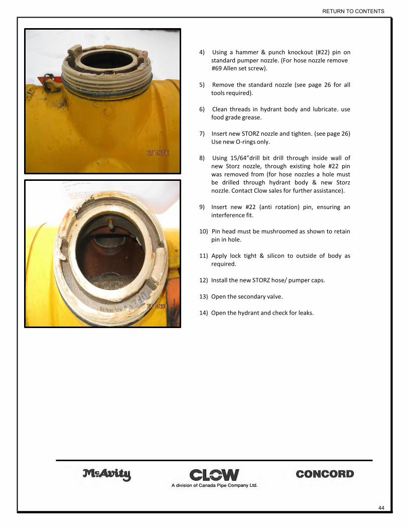
4) Using a hammer & punch knockout (#22) pin on standard pumper nozzle. (For hose nozzle remove #69 Allen set screw).
5) Remove the standard nozzle (see page 26 for all
tools required).
6) Clean threads in hydrant body and lubricate. use food grade grease.
7) Insert new STORZ nozzle and tighten. (see page 26)
Use new O-rings only.
8) Using 15/64”drill bit drill through inside wall of new Storz nozzle, through existing hole #22 pin was removed from (for hose nozzles a hole must be drilled through hydrant body & new Storz nozzle. Contact Clow sales for further assistance).
9) Insert new #22 (anti rotation) pin, ensuring an
interference fit.
10) Pin head must be mushroomed as shown to retain pin in hole.
11) Apply lock tight & silicon to outside of body as
required.
12) Install the new STORZ hose/ pumper caps.
13) Open the secondary valve.
14) Open the hydrant and check for leaks.
RETURN TO CONTENTS
44
TROUBLE SHOOTING
1. Problem: Hydrant stiff to operate
Possible cause:
o Improper installation of thrust bearing
o Frozen operating nut
o Insufficient lubrication
Solutions:
1. Thrust bearing (#12) must be installed above collar on (#64) op nut.
2. Older M67 hydrant with bell housing style op nut. – requires Hydralube op nut & upper stem
upgrade (page 37).
3. Hydrant requires proper lubrication – see page 34.
2. Problem: Hydrant spins freely won’t open or close
Possible cause:
o Broken ground line coupling or pin
o Lower stem damage
Solutions:
1. Check items #28 & 83 on page #6 for damage – follow procedure on page 33 to change.
2. Check lower stem for excessive corrosion allowing rounding / no engagement with drip valve.
Follow procedure on page 42 to change.
3. For older models only retained with #43 nut (page 9) corroded bottom end of stem allows for
total disengagement from operating nut. Lower stem must be replaced.
3. Problem: Water bypassing main valve, hydrant won’t completely shut off
Possible cause:
o Stone or forging matter lodged in main valve disc
o Damaged O-rings in main valve seat
RETURN TO CONTENTS
45

Solutions:
1. Follow procedure on page 33 to Check items 3434a,35 & 38 (page #6) for damage – follow
procedure on page 33 to change.
4. Problem: Lower stem main valve assembly wont thread into hydrant boot
Possible cause:
Damaged threads on main valve seat / seat ring
Solutions:
1. Call your local Clow Canada sales Representative for further assistance.
2. Check threads on #42 main valve seat, replace if required.
5. Problem: Flange segments crack while attaching upper body
Possible cause:
Uneven torque applied / over torqued bolts
Solutions:
1. Install and torque bolt & nuts evenly (using a cross tightening pattern) to a maximum of 80 ft.
Ib’s torque.
2. Try applying tightening force to nut below flange.
6. Problem: HYDRANT LEAKS - from around operating nut, or (#7) oil hole screw / at caps /at ground
line
Possible cause:
Faulty gaskets or O-rings at any of these locations.
Solutions:
1. Inspect O-ring & groove for damage, install new O-ring & clean groove.
2. Inspect gasket & seating surface for damage, clean & install new gasket.
RETURN TO CONTENTS
46

CLOW CANADA
1757 Burlington St. E. P.O. Box 2849
Hamilton, Ontario L8N 3R5 Tel: (905) 548-9604
Fax: (905) 547-0113
CLOW CANADA WARRANTY Clow warrants that the goods furnished hereunder will be free from defects in material and
workmanship under normal and customary use and maintenance for a period of ten years
for Resilient Wedge Gate Valves and twelve years for Fire Hydrants and one year for all
other product, from the earlier of date represented by the code cast on the goods or the
date of purchase, provided the goods are installed and maintained according to Clow's
instructions and applicable codes.
Hydrant paint and maintenance parts excluded from warranties beyond one year. The
foregoing warranty does not cover failure of any part or parts manufactured by others, which
shall be subject to the warranties of the manufacturers of said parts, and the foregoing
warranty does not cover failure of any part or parts from external forces, including but not
limited to earthquake, vandalism, vehicular or other impact, application of excessive torque
to the operating mechanism or frost heave.
Should any Clow part or parts fail to conform to the foregoing warranty, Clow shall, upon
prompt written notice thereof, repair or replace, F.O.B. point of manufacture, such defective
part or parts.
Buyer shall, if requested, return the part or parts to Clow, transportation prepaid.
RETURN TO CONTENTS
47

Buyer shall bear all responsibility and expense incurred for removal, reinstallation, and
shipping in connection with any part supplied under the foregoing warranty. Repair or
replacement as set forth shall be the buyers sole remedy, whether such claims are based
on breach of warranty, negligence or other theories.
THE FOREGOING WARRANTY IS IN LIEU OF AND EXCLUDES ALL OTHER
WARRANTIES NOT EXPRESSLY SET FORTH HEREIN, WHETHER EXPRESS OR
IMPLIED BY OPERATION OF LAW OR OTHERWISE, INCLUDING BUT NOT LIMITED TO
ANY WARRANTIES OF MERCHANTABILITY OR FITNESS, IN NO EVENT SHALL CLOW
CANADA BE RESPONSIBLE OR LIABLE FOR ANY INCIDENTAL OR CONSEQUENTIAL
LOSSES, DAMAGES OR EXPENSES.
Any claim by Buyer with reference to the goods sold hereunder for any cause shall be
deemed waived by Buyer unless submitted to Clow in writing within thirty (30) days from the
date Buyer discovered, or should have discovered any claimed breach.
RETURN TO CONTENTS
48