cloudvision portal (cvp) setup - arista.com · the ova file can be deployed as a vm in a vmware...
TRANSCRIPT

Configuration Guide: CloudVision version 2017.2.0 87
Chapter 5
CloudVision Portal (CVP) SetupCloudVision Portal (CVP) can be run on ESX or KVM hypervisors. Before you can begin using the CVP,you must complete the CVP setup process which, involves the following:
Step 1 Deploying CVP
Step 2 Configuring CVP
There are two different deployment procedures. One for deploying CVP on ESX, and one for deployingCVP on KVM. After you complete the deployment procedures, you then configure CVP. Thedeployment procedures are:
• “Deploying CVP OVA on ESX” on page 88
• “Deploying CVP on KVM” on page 92
There are two configuration methods for the CloudVision Portal (CVP): shell-based and ISO-based.Both of these methods eliminate the need to directly modify system and CVP configuration files. Thissimplifies the setup process and reduces the potential for issues.
The configuration methods enable you to configure CVP in both single-node systems and multi-nodesystems. The configuration methods are:
• “Shell-based Configuration” on page 97 (recommended)
• “ISO-based Configuration” on page 109
Note Reconfiguration of a deployed CVP multinode cluster is not supported.

88 Configuration Guide: CloudVision version 2017.2.0
Deploying CVP OVA on ESX Chapter 5: CloudVision Portal (CVP) Setup
5.1 Deploying CVP OVA on ESXDeploying the CVP OVA file should be the first step in any setup. After the CVP OVA file is deployed,you can chose between the two configuration methods for CloudVision Portal (CVP).
Pre-requisites: Use of the Deploy OVF Template requires the VMware Client Integration plugin, whichis not supported by the Chrome browser after versions 42.
Step 1 The OVA file can be deployed as a VM in a VMware environment by using the drop menuunder the Actions heading and selecting Deploy OVF Template (Figure 5-1).
Note For multi-node setups, the following steps must be completed 3 times to launch 3 VMs (once for eachVM).
Figure 5-1: Deploy the OVA template
Step 2 Having selected the Deploy OVF Template option, VCenter will prompt for the location of theOVA file; this can be either on a local hard disk, network share, or Internet URL. The locationof the OVA file should be entered or selected (Figure 5-2 on page 89).

Chapter 5: CloudVision Portal (CVP) Setup Deploying CVP OVA on ESX
Configuration Guide: CloudVision version 2017.2.0 89
Figure 5-2: Location of the OVA file
Step 3 Click Next to go to the next task.
Step 4 Review the OVA template details (Figure 5-3).
Figure 5-3: Review OVA template details
Step 5 Click Next to go to the next task.
Step 6 Type the name for the OVA file in the Name field and select the folder for the OVA file(Figure 5-4 on page 90).

90 Configuration Guide: CloudVision version 2017.2.0
Deploying CVP OVA on ESX Chapter 5: CloudVision Portal (CVP) Setup
Figure 5-4: Select name and folder location for OVA file
Step 7 Click Next to go to the next task.
Step 8 Select the resource where you want the deployed template (OVA file) to be run (Figure 5-5).
Figure 5-5: Select the resource
Step 9 Click Next to go to the next task.
Step 10 Select the location where you want the files for the deployed template to be stored. You canchoose the virtual disk format (Figure 5-6 on page 91).

Chapter 5: CloudVision Portal (CVP) Setup Deploying CVP OVA on ESX
Configuration Guide: CloudVision version 2017.2.0 91
Figure 5-6: Select the destination storage
Step 11 Click Next to go to the next task.
Step 12 Setup the networks that the deployed template should use (Figure 5-7).
Figure 5-7: Setup the networks
Step 13 Click Next.
VCenter loads the OVA and displays the configuration settings (Figure 5-8 on page 92).

92 Configuration Guide: CloudVision version 2017.2.0
Deploying CVP on KVM Chapter 5: CloudVision Portal (CVP) Setup
Figure 5-8: Select the “Finish” button to accept these settings
Step 14 Review the configuration settings, and click Finish to accept and save the configuration.
VCenter begins to deploy the virtual appliance. Once the appliance is deployed, you canconfigure the CVP application.
Related topics:
• “Deploying CVP on KVM”
• “Shell-based Configuration” on page 97
• “ISO-based Configuration” on page 109
5.2 Deploying CVP on KVMIn standard KVM environments, deploying a CVP VM involves the following tasks:
• “Downloading and extracting the CVP KVM tarball (.tgz archive)”
• “Creating Virtual Bridge and Network Interface Cards (NIC)” on page 93
• “Generating the XML file that defines the CVP VM” on page 96
• “Defining and launching the CVP VM” on page 96
Once you complete these tasks, you can configure the CVP VM.
5.2.1 Downloading and extracting the CVP KVM tarball (.tgz archive)
The first task in the deployment process involves downloading and extracting the CVP KVM tarball. Thetarball is a .tgz archive that contains:
• The CVP VM
• Disk images for the CVP application
• The files used to configure CVP VM.

Chapter 5: CloudVision Portal (CVP) Setup Deploying CVP on KVM
Configuration Guide: CloudVision version 2017.2.0 93
You download the tarball to the host server that is configured for KVM. The files contained in the .tgzarchive include:
Filename Description1 disk1.qcow2 VM disk image for the CVP application.
2 disk2.qcow2 Data disk image for the CVP application.
3 cvpTemplate.xml A template for creating the XML file for libvirt domain specification.
4 generateXmlForKvm.py A script for generating the CVP VM definition XML based on the XML template.
5 createNwBridges.py A script for creating the network interfaces for the CVP VM.
Complete the following steps to download and extract the CVP VM .tgz archive:
Step 1 Go to the Arista software downloads webpage and download the CVP VM tarball(cvp-<version>-kvm.tgz) to the host server set up for KVM.
Step 2 Extract the tarball (cvp-<version>-kvm.tgz).
Figure 5-9 shows an example of extracting the CVP KVM .tgz archive.
Figure 5-9: Example: Extracting the cvp kvm .tgz archive
5.2.2 Creating Virtual Bridge and Network Interface Cards (NIC)
The second task in deploying CVP for KVM involves creating the bridges and interfaces that providenetwork connectivity for the CVP VM. You use the CreateNwBridges.py script you extracted in theprevious task to create the required bridges and interfaces.
Note If the required network interfaces for CVP already exist, you do not have to complete this task. Godirectly to “Generating the XML file that defines the CVP VM” on page 96.
You have the option of deploying CVP with either 2 bridge interfaces or a single bridge interface.
• Two interfaces (the cluster bridge interface and the device bridge interface)
• Single interface (the device bridge interface).
Complete the following steps to create the network interfaces for CVP KVM connectivity:
Step 1 (Optional) Use the ./createNwBridges.py –-help command to view a list of all theparameters available in the script.
Step 2 Use the ./createNwBridges.py to create the device bridge (or bridges) and interfacesneeded.

94 Configuration Guide: CloudVision version 2017.2.0
Deploying CVP on KVM Chapter 5: CloudVision Portal (CVP) Setup
Figure 5-10 shows an example of creating a single device bridge for a single-node deployment.
Figure 5-10: Example: Creating a device bridge (single node deployment)
Step 3 (Optional) Use the brctl show command to verify that the bridges were successfully created.
Step 4 (Optional) Use the ifconfig command to verify that the IP addresses have been allocated.In this example the one IP address for the br1 bridge.
Figure 5-11 on page 95 shows an example of verification of bridge creation and IP addressallocation. In this example, a bridge br1 was created, and one IP address has been allocatedfor the bridge.

Chapter 5: CloudVision Portal (CVP) Setup Deploying CVP on KVM
Configuration Guide: CloudVision version 2017.2.0 95
Figure 5-11: Example: Verification of bridge creation and IP address allocation

96 Configuration Guide: CloudVision version 2017.2.0
Deploying CVP on KVM Chapter 5: CloudVision Portal (CVP) Setup
5.2.3 Generating the XML file that defines the CVP VM
The third task in deploying CVP for KVM involves generating the XML file that you use to define theCVP VM. You use generateXmlForKvm.py script and the cvpTemplate.xml file you extractedpreviously to generate the XML file you use to define the CVP VM.
The cvpTemplate.xml file is a template that defines wildcard values that are filled by the otherparameters that are specified when you execute the script.
Complete the following steps to generate the XML file:
Step 1 (Optional) Use the ./generateXmlForKvm.py –-help command to view a list of all theparameters available in the script.
Step 2 Run the ./generateXmlForKvm.py script using the XML template (cvpTemplate.xml) asone of the inputs.
Figure 5-12 shows an example of an XML being generated that can be used to define a CVPVM named cvpTest. The generated XML file is named qemuout.xml.
Figure 5-12: Example: Generation of XML file used to define CVP VM
5.2.4 Defining and launching the CVP VM
The last task in deploying CVP for KVM is to define and launch the CVP VM. You use the XML file yougenerated in the previous task to define the CVP VM.
Complete the following steps to define and launch the CVP VM:
Step 1 Run the virsh define command to define the CVP VM (specify the generated XML file).
Step 2 Run the virsh start command to launch the newly defined CVP VM.
Step 3 Run the virsh console command to attach (connect) to the CVP VM console.
Figure 5-13 on page 97 shows an example of the use of the commands to define and launcha CVP VM named cvpTest. The XML file used to define the CVP VM is named qemuout.xml.

Chapter 5: CloudVision Portal (CVP) Setup Shell-based Configuration
Configuration Guide: CloudVision version 2017.2.0 97
Figure 5-13: Example: Defining and launching the CVP VM
You can now login as cvpadmin and complete the configuration of the CVP application. See“Configuring a single-node CVP instance using the CVP shell” on page 98 for the steps used tocomplete the configuration.
Related topics:
• “Shell-based Configuration”
• “ISO-based Configuration” on page 109
• “Deploying CVP OVA on ESX” on page 88
5.3 Shell-based ConfigurationThe shell-based configuration can be used to set up either a single-node CVP instance or multi-nodeCVP instances. The steps you use vary depending on whether you are setting up a single-nodeinstance or a multi-node instance.
Cluster and device interfaces
A cluster interface is the interface that is able to reach the other two nodes in a multi-node installation.A device interface is the interface used by managed devices to connect to CVP. The ZTP configurationfile is served over this interface. These two parameters are optional and default to eth0. Configuringthese two interfaces is useful in deployments where a private network is used between the manageddevices and a public-facing network is used to reach the other two cluster nodes and the GUI.
• “Configuring a single-node CVP instance using the CVP shell” on page 98
• “Configuring multi-node CVP instances using the CVP shell” on page 98

98 Configuration Guide: CloudVision version 2017.2.0
Shell-based Configuration Chapter 5: CloudVision Portal (CVP) Setup
5.3.1 Configuring a single-node CVP instance using the CVP shell
After initial bootup, CVP can be configured at the VM’s console using the CVP config shell. At pointsduring the configuration, you must start the network, NTPD, and CVP services. Starting these servicesmay take some time to complete before moving on to the next step in the process.
Pre-requisites: Before you begin the configuration process, make sure that you:
• Launch the VM (see “Deploying CVP OVA on ESX” on page 88, or “Deploying CVP on KVM” onpage 92.)
To configure CVP using the CVP config shell:
Step 1 Login at the VM console as “cvpadmin”.
Step 2 Enter your configuration and apply it (see the following example).
Example:
In this example, the root password is not set (it is not set by default). In this example of a CVP shell,the bold text is entered by the “cvpadmin” user.
CentOS Linux 7 (Core)Kernel 3.10.0-327.10.1.el7.x86_64 on an x86_64
localhost login: cvpadminChanging password for user root.New password:Retype new password:passwd: all authentication tokens updated successfully.Enter a command [q]uit [p]rint [s]inglenode [m]ultinode [r]eplace [u]pgrade>s
Enter the configuration for CloudVision Portal and apply it when done.Entries marked with '*' are required.
common configuration: default route: 172.31.0.1 dns: 172.22.22.40 ntp: ntp.aristanetworks.com Telemetry Ingest Key: magickey Cluster Interface name: eth0 Device Interface name: eth0node configuration: *hostname (fqdn): cvp6.sjc.aristanetworks.com *IP address of eth0: 172.31.3.236 *Netmask of eth0: 255.255.0.0[q]uit [p]rint [e]dit [v]erify [s]ave [a]pply [h]elp ve[r]bose>vValid config.>a
5.3.2 Configuring multi-node CVP instances using the CVP shell
Use this procedure to configure multi-node CVP instances using the CVP shell. This procedureincludes the steps to set up a primary, secondary, and tertiary node, which is the number of nodesrequired for redundancy. It also includes the steps to verify and apply the configuration of each node.
The sequence of steps in this procedure follow the process described in “The basic steps in theprocess” on page 101.

Chapter 5: CloudVision Portal (CVP) Setup Shell-based Configuration
Configuration Guide: CloudVision version 2017.2.0 99
Pre-requisites: Before you begin the configuration process, make sure that you:
• Launch the VM (see “Deploying CVP OVA on ESX” on page 88, or “Deploying CVP on KVM” onpage 92.)
• Login to the VM console for each of the 3 nodes (login as “cvpadmin” on each node).
Note To configure three different default route parameters, one for each node, do the following:1. Leave the default route in the common configuration section empty.
For example,common configuration:
default route:...2. Enter the default route in the node-level section.
For example,node configuration:
default route: 172.31.0.1.
Complete the following steps to configure multi-node CVP instances:
Step 1 Login at the VM console for the primary node as “cvpadmin”.
Step 2 At the “cvp installation mode” prompt, type “m” to select a multi-node configuration.
Step 3 At the prompt to select a role for the node, type “p” to select primary node.
Note You must select primary first. You cannot configure one of the other nodes before you configure theprimary node.
Step 4 Follow the CloudVision Portal prompts to specify the configuration options for the primarynode. (All options with an asterisk (*) are required.) The options include:
• Root password (*)
• Default route (*)
• DNS (*)
• NTP (*)
• Telemetry Ingest Key
• Cluster interface name (*)
• Device interface name (*)
• Hostname (*)
• IP address (*)
• Netmask (*)
Note If there are separate cluster and device interfaces (the interfaces have different IP addresses), makesure that you enter the hostname of the cluster interface. If the cluster and device interface are thesame (for example, they are “eth0”), make sure you enter the IP address of “eth0” for the hostname.
Step 5 At the following prompt, type “v” to verify the configuration.[q]uit, [p]rint, [e]dit, [v]erify, [s]ave, [a]pply, [h]elp ve[r]bose.
If the configuration is valid, the system shows a “Valid config” status message.
Step 6 Type “a” to apply the configuration for the primary node.
100 Configuration Guide: CloudVision version 2017.2.0
Shell-based Configuration Chapter 5: CloudVision Portal (CVP) Setup
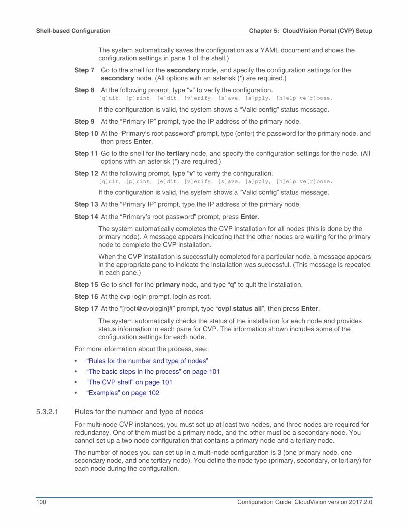
The system automatically saves the configuration as a YAML document and shows theconfiguration settings in pane 1 of the shell.)
Step 7 Go to the shell for the secondary node, and specify the configuration settings for thesecondary node. (All options with an asterisk (*) are required.)
Step 8 At the following prompt, type “v” to verify the configuration.[q]uit, [p]rint, [e]dit, [v]erify, [s]ave, [a]pply, [h]elp ve[r]bose.
If the configuration is valid, the system shows a “Valid config” status message.
Step 9 At the “Primary IP” prompt, type the IP address of the primary node.
Step 10 At the “Primary’s root password” prompt, type (enter) the password for the primary node, andthen press Enter.
Step 11 Go to the shell for the tertiary node, and specify the configuration settings for the node. (Alloptions with an asterisk (*) are required.)
Step 12 At the following prompt, type “v” to verify the configuration.[q]uit, [p]rint, [e]dit, [v]erify, [s]ave, [a]pply, [h]elp ve[r]bose.
If the configuration is valid, the system shows a “Valid config” status message.
Step 13 At the “Primary IP” prompt, type the IP address of the primary node.
Step 14 At the “Primary’s root password” prompt, press Enter.
The system automatically completes the CVP installation for all nodes (this is done by theprimary node). A message appears indicating that the other nodes are waiting for the primarynode to complete the CVP installation.
When the CVP installation is successfully completed for a particular node, a message appearsin the appropriate pane to indicate the installation was successful. (This message is repeatedin each pane.)
Step 15 Go to shell for the primary node, and type “q” to quit the installation.
Step 16 At the cvp login prompt, login as root.
Step 17 At the “[root@cvplogin]#” prompt, type “cvpi status all”, then press Enter.
The system automatically checks the status of the installation for each node and providesstatus information in each pane for CVP. The information shown includes some of theconfiguration settings for each node.
For more information about the process, see:
• “Rules for the number and type of nodes”
• “The basic steps in the process” on page 101
• “The CVP shell” on page 101
• “Examples” on page 102
5.3.2.1 Rules for the number and type of nodes
For multi-node CVP instances, you must set up at least two nodes, and three nodes are required forredundancy. One of them must be a primary node, and the other must be a secondary node. Youcannot set up a two node configuration that contains a primary node and a tertiary node.
The number of nodes you can set up in a multi-node configuration is 3 (one primary node, onesecondary node, and one tertiary node). You define the node type (primary, secondary, or tertiary) foreach node during the configuration.

Chapter 5: CloudVision Portal (CVP) Setup Shell-based Configuration
Configuration Guide: CloudVision version 2017.2.0 101
5.3.2.2 The basic steps in the process
All multi-node configurations follow the same basic process. The basic steps are:
Step 1 Specify the settings for the nodes in the following sequence (you apply the configuration laterin the process):
• Primary node
• Secondary node
• Tertiary node
Step 2 Verify and then apply the configuration for the primary node. (During this step, the systemautomatically saves the configuration for the primary node as a YAML document. In addition,the system shows the configuration settings.)
Once the system applies the configuration for the primary node, the other nodes send theirhostname and IP address to the primary node.
Step 3 Verify and then apply the configuration for the secondary node.
As part of this step, the system automatically pushes the hostname, IP address, and public keyof the secondary node to the primary node. The primary node also sends a consolidated YAMLto the secondary node, which is required to complete the configuration of the secondary node.
Step 4 The previous step (verifying and applying the configuration) is repeated for the tertiary node.(The automated processing of data described for the secondary node is also repeated for thetertiary node.)
Once the configuration for all nodes has been applied (steps 1 through 4 above), the systemautomatically attempts to complete the CVP installation for all nodes (this is done by theprimary node). A message appears indicating that the other nodes are waiting for the primarynode to complete the CVP installation.
Step 5 You quit the installation, then login as root and check the status of CVP.
The system automatically checks the status and provides status information in each pane forthe CVP service.
5.3.2.3 The CVP shell
For multi-node configurations, you need to open 3 CVP consoles (one for each node). Each console isshown in it's own pane. You use each console to configure one of the nodes (primary, secondary, ortertiary).
The system also provides status messages and all of the options required to complete the multi-nodeconfiguration. The status messages and options are presented in the panes of the shell thatcorrespond to the node type.
Figure 5-14 on page 102 shows 3 CVP Console shells for multi-node configurations. Each shellcorresponds to a CVP Console for each node being configured.

102 Configuration Guide: CloudVision version 2017.2.0
Shell-based Configuration Chapter 5: CloudVision Portal (CVP) Setup
Figure 5-14: CVP Console shells for multi-node configurations
5.3.2.4 Examples
The following examples show the commands used to configure (set up) the primary, secondary, andtertiary nodes, and apply the configurations to the nodes. Examples are also included of the systemoutput shown as CVP completes the installation for each of the nodes.
• “Primary node configuration” on page 103
• “Secondary node configuration” on page 104
• “Tertiary node configuration” on page 105
• “Verifying the primary node configuration and applying it to the node” on page 105
• “Verifying the secondary and tertiary node configurations and applying them to the nodes” onpage 106
• “Waiting for the primary node installation to finish” on page 107
• “Waiting for the secondary and tertiary node installation to finish” on page 108

Chapter 5: CloudVision Portal (CVP) Setup Shell-based Configuration
Configuration Guide: CloudVision version 2017.2.0 103
Primary node configuration
This example shows the commands used to configure (set up) the primary node.
localhost login: cvpadminChanging password for user root.New password:BAD PASSWORD: The password is shorter than 8 charactersRetype new password:passwd: all authentication tokens updated successfully.Choose CVP installation mode[s]inglenode [m]ultinode [r]eplace [u]pgrade>mChoose a role for the node, roles should be mutually exclusive[p]rimary [s]econdary [t]ertiary>p
Enter the configuration for CloudVision Portal and apply it when done.Entries marked with '*' are required.
common configuration: default route: 172.31.0.1 dns: ntp:Telemetry Ingest Key: magickey Cluster Interface name: eth0 Device Interface name: eth0node configuration: *hostname (fqdn): cvp79.sjc.aristanetworks.com *dns: 172.22.22.40 *ntp: 0.fedora.pool.ntp.org *IP address of eth0: 172.31.0.167 *Netmask of eth0: 255.255.0.0[q]uit [p]rint [e]dit [v]erify [s]ave [a]pply [h]elp ve[r]bose>

104 Configuration Guide: CloudVision version 2017.2.0
Shell-based Configuration Chapter 5: CloudVision Portal (CVP) Setup
Secondary node configuration
This example shows the commands used to configure (set up) the secondary node.
localhost login: cvpadminChanging password for user root.New password:BAD PASSWORD: The password is shorter than 8 charactersRetype new password:passwd: all authentication tokens updated successfully.Choose CVP installation mode[s]inglenode [m]ultinode [r]eplace [u]pgrade>mChoose a role for the node, roles should be mutually exclusive[p]rimary [s]econdary [t]ertiary>s
Enter the configuration for CloudVision Portal and apply it when done.Entries marked with '*' are required.
common configuration: default route: 172.31.0.1 dns: ntp:Telemetry Ingest Key: magickey Cluster Interface name: eth0 Device Interface name: eth0node configuration: *hostname (fqdn): cvp82.sjc.aristanetworks.com *dns: 172.22.22.40 *ntp: 0.fedora.pool.ntp.org *IP address of eth0: 172.31.0.211 *Netmask of eth0: 255.255.0.0[q]uit [p]rint [e]dit [v]erify [s]ave [a]pply [h]elp ve[r]bose>
Chapter 5: CloudVision Portal (CVP) Setup Shell-based Configuration
Configuration Guide: CloudVision version 2017.2.0 105
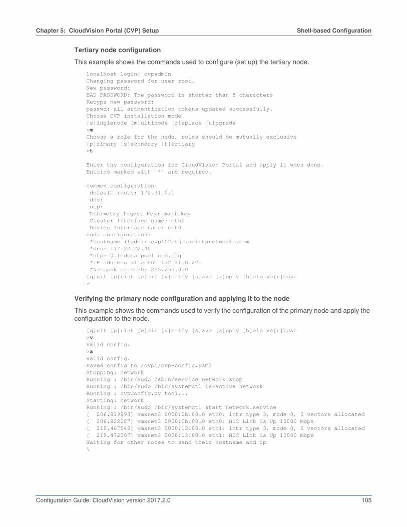
Tertiary node configuration
This example shows the commands used to configure (set up) the tertiary node.
localhost login: cvpadminChanging password for user root.New password:BAD PASSWORD: The password is shorter than 8 charactersRetype new password:passwd: all authentication tokens updated successfully.Choose CVP installation mode[s]inglenode [m]ultinode [r]eplace [u]pgrade>mChoose a role for the node, roles should be mutually exclusive[p]rimary [s]econdary [t]ertiary>t
Enter the configuration for CloudVision Portal and apply it when done.Entries marked with '*' are required.
common configuration: default route: 172.31.0.1 dns: ntp:Telemetry Ingest Key: magickey Cluster Interface name: eth0 Device Interface name: eth0node configuration: *hostname (fqdn): cvp102.sjc.aristanetworks.com *dns: 172.22.22.40 *ntp: 0.fedora.pool.ntp.org *IP address of eth0: 172.31.0.221 *Netmask of eth0: 255.255.0.0[q]uit [p]rint [e]dit [v]erify [s]ave [a]pply [h]elp ve[r]bose>
Verifying the primary node configuration and applying it to the node
This example shows the commands used to verify the configuration of the primary node and apply theconfiguration to the node.
[q]uit [p]rint [e]dit [v]erify [s]ave [a]pply [h]elp ve[r]bose>vValid config.>aValid config.saved config to /cvpi/cvp-config.yamlStopping: networkRunning : /bin/sudo /sbin/service network stopRunning : /bin/sudo /bin/systemctl is-active networkRunning : cvpConfig.py tool...Starting: networkRunning : /bin/sudo /bin/systemctl start network.service[ 206.819893] vmxnet3 0000:0b:00.0 eth0: intr type 3, mode 0, 5 vectors allocated[ 206.822287] vmxnet3 0000:0b:00.0 eth0: NIC Link is Up 10000 Mbps[ 219.467548] vmxnet3 0000:13:00.0 eth1: intr type 3, mode 0, 5 vectors allocated[ 219.472007] vmxnet3 0000:13:00.0 eth1: NIC Link is Up 10000 MbpsWaiting for other nodes to send their hostname and ip\
106 Configuration Guide: CloudVision version 2017.2.0
Shell-based Configuration Chapter 5: CloudVision Portal (CVP) Setup
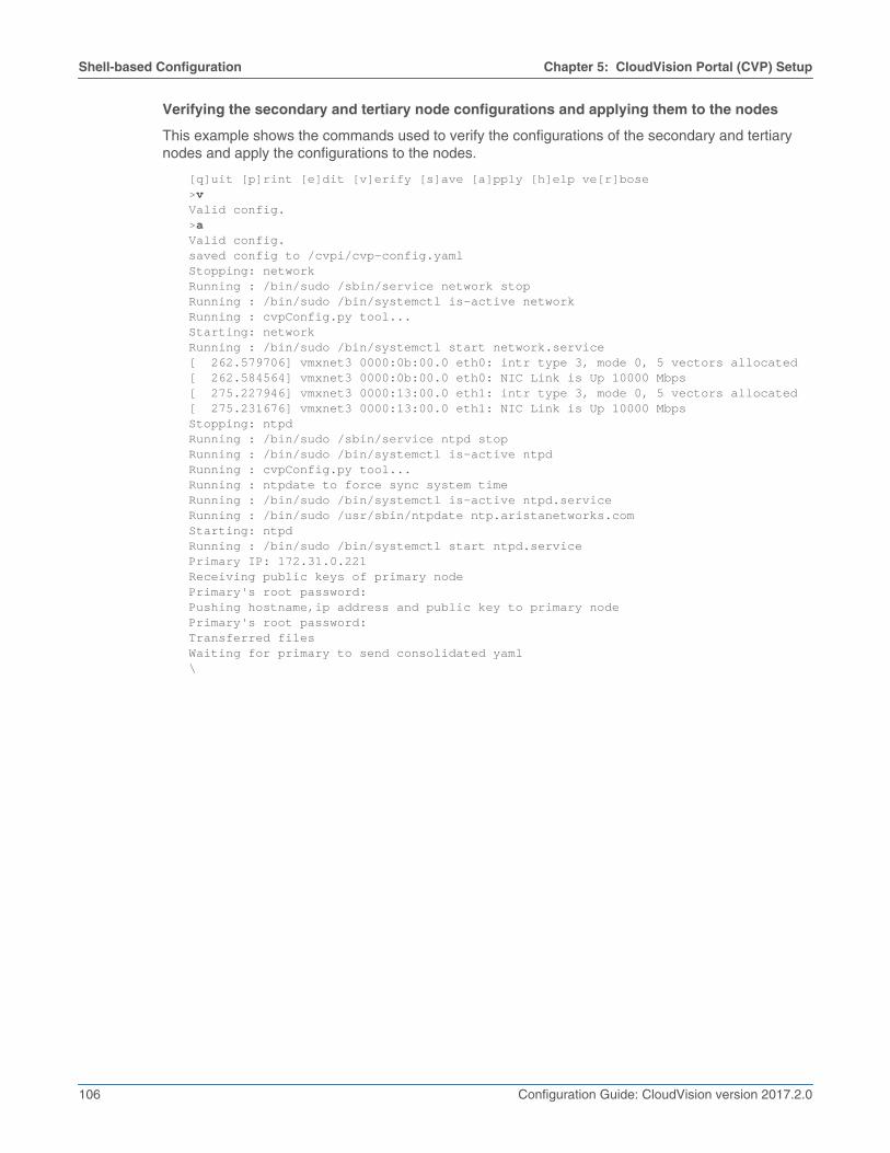
Verifying the secondary and tertiary node configurations and applying them to the nodes
This example shows the commands used to verify the configurations of the secondary and tertiarynodes and apply the configurations to the nodes.
[q]uit [p]rint [e]dit [v]erify [s]ave [a]pply [h]elp ve[r]bose>vValid config.>aValid config.saved config to /cvpi/cvp-config.yamlStopping: networkRunning : /bin/sudo /sbin/service network stopRunning : /bin/sudo /bin/systemctl is-active networkRunning : cvpConfig.py tool...Starting: networkRunning : /bin/sudo /bin/systemctl start network.service[ 262.579706] vmxnet3 0000:0b:00.0 eth0: intr type 3, mode 0, 5 vectors allocated[ 262.584564] vmxnet3 0000:0b:00.0 eth0: NIC Link is Up 10000 Mbps[ 275.227946] vmxnet3 0000:13:00.0 eth1: intr type 3, mode 0, 5 vectors allocated[ 275.231676] vmxnet3 0000:13:00.0 eth1: NIC Link is Up 10000 MbpsStopping: ntpdRunning : /bin/sudo /sbin/service ntpd stopRunning : /bin/sudo /bin/systemctl is-active ntpdRunning : cvpConfig.py tool...Running : ntpdate to force sync system timeRunning : /bin/sudo /bin/systemctl is-active ntpd.serviceRunning : /bin/sudo /usr/sbin/ntpdate ntp.aristanetworks.comStarting: ntpdRunning : /bin/sudo /bin/systemctl start ntpd.servicePrimary IP: 172.31.0.221Receiving public keys of primary nodePrimary's root password:Pushing hostname,ip address and public key to primary nodePrimary's root password:Transferred filesWaiting for primary to send consolidated yaml\

Chapter 5: CloudVision Portal (CVP) Setup Shell-based Configuration
Configuration Guide: CloudVision version 2017.2.0 107
Waiting for the primary node installation to finish
This example shows the system output shown as CVP completes the installation for the primary node.
[q]uit [p]rint [e]dit [v]erify [s]ave [a]pply [h]elp ve[r]bose>vValid config.>aValid config.saved config to /cvpi/cvp-config.yamlStopping: networkRunning : /bin/sudo /sbin/service network stopRunning : /bin/sudo /bin/systemctl is-active networkRunning : cvpConfig.py tool...Starting: networkRunning : /bin/sudo /bin/systemctl start network.service[ 206.819893] vmxnet3 0000:0b:00.0 eth0: intr type 3, mode 0, 5 vectors allocated[ 206.822287] vmxnet3 0000:0b:00.0 eth0: NIC Link is Up 10000 Mbps[ 219.467548] vmxnet3 0000:13:00.0 eth1: intr type 3, mode 0, 5 vectors allocated[ 219.472007] vmxnet3 0000:13:00.0 eth1: NIC Link is Up 10000 MbpsWaiting for other nodes to send their hostname and ip-Stopping: ntpdRunning : /bin/sudo /sbin/service ntpd stopRunning : /bin/sudo /bin/systemctl is-active ntpdRunning : cvpConfig.py tool...[ 285.932940] Ebtables v2.0 unregistered[ 286.323740] ip_tables: (C) 2000-2006 Netfilter Core Team[ 286.349425] nf_conntrack version 0.5.0 (65536 buckets, 262144 max)[ 286.362088] ip6_tables: (C) 2000-2006 Netfilter Core Team[ 286.400565] Ebtables v2.0 registeredRunning : ntpdate to force sync system timeRunning : /bin/sudo /bin/systemctl is-active ntpd.serviceRunning : /bin/sudo /usr/sbin/ntpdate ntp.aristanetworks.comStarting: ntpdRunning : /bin/sudo /bin/systemctl start ntpd.serviceVerifying configuration on the secondary nodeVerifying configuration on the tertiary nodeStarting: cvpi and cvp appStarting: cvpi-checkRunning : /bin/sudo /bin/systemctl start cvpi-check.serviceStarting: zookeeperRunning : /bin/sudo /bin/systemctl start zookeeper.serviceStarting: cvpi and apps[ 358.873111] FS-Cache: Loaded[ 359.009859] FS-Cache: Netfs 'nfs' registered for cachingStarting: cvpi-configRunning : /bin/sudo /bin/systemctl start cvpi-config.serviceStarting: cvpiRunning : /bin/sudo /bin/systemctl start cvpi.serviceRunning : /bin/sudo /bin/systemctl enable zookeeperCVP installation successful[q]uit [p]rint [e]dit [v]erify [s]ave [a]pply [h]elp ve[r]bose>q

108 Configuration Guide: CloudVision version 2017.2.0
Shell-based Configuration Chapter 5: CloudVision Portal (CVP) Setup
Waiting for the secondary and tertiary node installation to finish
This example shows the system output displayed as CVP completes the installation for the secondaryand tertiary nodes.
[q]uit [p]rint [e]dit [v]erify [s]ave [a]pply [h]elp ve[r]bose>vValid config.>ssaved config to /cvpi/cvp-config.yaml>aValid config.saved config to /cvpi/cvp-config.yamlStopping: networkRunning : /bin/sudo /sbin/service network stopRunning : /bin/sudo /bin/systemctl is-active networkRunning : cvpConfig.py tool...Starting: networkRunning : /bin/sudo /bin/systemctl start network.service[ 229.786202] vmxnet3 0000:0b:00.0 eth0: intr type 3, mode 0, 5 vectors allocated[ 229.789872] vmxnet3 0000:0b:00.0 eth0: NIC Link is Up 10000 Mbps[ 242.417418] vmxnet3 0000:13:00.0 eth1: intr type 3, mode 0, 5 vectors allocated[ 242.421471] vmxnet3 0000:13:00.0 eth1: NIC Link is Up 10000 MbpsStopping: ntpdRunning : /bin/sudo /sbin/service ntpd stopRunning : /bin/sudo /bin/systemctl is-active ntpdRunning : cvpConfig.py tool...Running : ntpdate to force sync system timeRunning : /bin/sudo /bin/systemctl is-active ntpd.serviceRunning : /bin/sudo /usr/sbin/ntpdate ntp.aristanetworks.comStarting: ntpdRunning : /bin/sudo /bin/systemctl start ntpd.servicePrimary IP: 172.31.0.221Receiving public keys of primary nodePrimary's root password:Pushing hostname,ip address and public key to primary nodePrimary's root password:Transferred filesWaiting for primary to send consolidated yaml-Stopping: zookeeperRunning : /bin/sudo /sbin/service zookeeper stopRunning : /bin/sudo /bin/systemctl is-active zookeeperStopping: cvpi-checkRunning : /bin/sudo /sbin/service cvpi-check stopRunning : /bin/sudo /bin/systemctl is-active cvpi-checkStopping: ntpdRunning : /bin/sudo /sbin/service ntpd stopRunning : /bin/sudo /bin/systemctl is-active ntpdRunning : cvpConfig.py tool...[ 292.218447] Ebtables v2.0 unregistered[ 292.639001] ip_tables: (C) 2000-2006 Netfilter Core Team[ 292.673426] nf_conntrack version 0.5.0 (65536 buckets, 262144 max)[ 292.688565] ip6_tables: (C) 2000-2006 Netfilter Core Team[ 292.734061] Ebtables v2.0 registeredRunning : ntpdate to force sync system timeRunning : /bin/sudo /bin/systemctl is-active ntpd.serviceRunning : /bin/sudo /usr/sbin/ntpdate ntp.aristanetworks.comStarting: ntpdRunning : /bin/sudo /bin/systemctl start ntpd.serviceStarting: cvpi-checkRunning : /bin/sudo /bin/systemctl start cvpi-check.service

Chapter 5: CloudVision Portal (CVP) Setup ISO-based Configuration
Configuration Guide: CloudVision version 2017.2.0 109
Starting: zookeeperRunning : /bin/sudo /bin/systemctl start zookeeper.serviceRunning : /bin/sudo /bin/systemctl enable zookeeperWaiting for primary to finish configuring cvp.-Please wait for primary to complete cvp installation.[q]uit [p]rint [e]dit [v]erify [s]ave [a]pply [h]elp ve[r]bose>q
5.4 ISO-based ConfigurationThe ISO-based configuration can be used to set up either a single-node or multi-node CVP instance(s).Before configuring and starting CVP, the following tasks must be completed.
Quick Start Steps:
• Launch the VM (see “Deploying CVP OVA on ESX” on page 88, or “Deploying CVP on KVM” onpage 92).
• “Create a YAML document”
• “Feed the YAML file into the geniso.py tool” on page 110.
• “Map the ISO to the VM’s CDROM Drive” on page 111.
• Verify the host name, reachability of the name server, and VM connectivity.
5.4.1 Create a YAML document
Create a YAML document describing the node(s) (one or three) in your CVP deployment. Whencreating a YAML document, the following should be considered:
• The version field is required and must be 2.
• The "dns" and "ntp" entries are lists of values.
• The "dns", and "ntp" parameters are optional, but recommended to use.
Note The parameters, which are the same for all nodes, can be specified only once in the “common” sectionof the YAML. For example, "default_route" can be specified only once in the common section and notthree times, once for each node.
Example:
The following example of a YAML document shows the use of separate (different) interfaces for clusterand device-facing networks. These parameters are explained in the previous section. For a single-nodedeployment, remove the sections for "node2" and "node3" (assuming all nodes are on the same subnetand have the same default route).
>cat multinode.yamlversion: 2common: aeris_ingest_key: magickey cluster_interface: eth0 default_route: 172.31.0.1 device_interface: eth0 dns: - 172.22.22.40 ntp: - ntp.aristanetworks.com

110 Configuration Guide: CloudVision version 2017.2.0
ISO-based Configuration Chapter 5: CloudVision Portal (CVP) Setup
node1:hostname: cvp6.sjc.aristanetworks.cominterfaces:
eth0:ip_address: 172.31.3.236netmask: 255.255.0.0
vmname: cvp6
node2: vmname: cvp9 hostname : cvp9.sjc.aristanetworks.com interfaces: eth0: ip_address: 172.31.3.239 netmask: 255.255.0.0 eth1: ip_address: 10.0.0.2 netmask: 255.255.255.0node3: vmname: cvp10 hostname: cvp10.sjc.aristanetworks.com interfaces: eth0: ip_address: 172.31.3.240 netmask: 255.255.0.0 eth1: ip_address: 10.0.0.3 netmask: 255.255.255.0
5.4.2 Feed the YAML file into the geniso.py tool
Once you have created the YAML file, you are ready to feed it into the tool so that you can generate theISO files for the CVP nodes. The root password can be provided at the command line or prompted fromthe user. If password is empty, no password will be set for root.
Note The geniso.py tool is provided by cvp-tools-1.0.1.tgz which can be found athttps://www.arista.com/en/support/software-download. The package also contains a README file withmore details and requirements for geniso.py.
Complete the following steps:
Step 1 Run the "yum install mkisofs" command.
Step 2 Feed the YAML document into the geniso.py tool.
The system generates the ISO files for the nodes using the input of the YAML document.
Example:
• In this example, you are prompted for the root password.
> mkdir tools> tar zxf cvp-tools-1.0.1.tgz -C tools> cd tools
...<edit multinode.yaml>...
> ./geniso.py -y multinode.yamlPlease enter a password for root user on cvpPassword:

Chapter 5: CloudVision Portal (CVP) Setup ISO-based Configuration
Configuration Guide: CloudVision version 2017.2.0 111
Please re-enter the password:Building ISO for node1 cvp1: cvp.iso.2015-11-04_00:16:23/node1-cvp1.isoBuilding ISO for node2 cvp2: cvp.iso.2015-11-04_00:16:23/node2-cvp2.isoBuilding ISO for node3 cvp3: cvp.iso.2015-11-04_00:16:23/node3-cvp3.iso
5.4.3 Map the ISO to the VM’s CDROM Drive
Step 1 Through vSphere, edit the VM's created by step 1 in the procedure “Deploying CVP OVA onESX” on page 88 to map the appropriate ISO file to the VM's CDROM.
Note For multi-node setups, steps 1 and 2 will have to be completed 3 times to input the 3 ISO files for the3 VMs (once for each VM).
In this example (Figure 5-15), the ISO was previously copied to the Datastore on the ESX host.
Figure 5-15: vSphere view of a previous configuration
Step 2 On first boot, the CVP instance(s) will mount the ISO, read the configuration and apply it tothe CVP instance (Figure 5-16 on page 112).

112 Configuration Guide: CloudVision version 2017.2.0
ISO-based Configuration Chapter 5: CloudVision Portal (CVP) Setup
Figure 5-16: Applying the configuration
Step 3 Login to the primary node (node1 from the YAML file) as root, change to user cvp “su cvp”,and run “cvpi start all”.
Within a few minutes you should see that the CVP application is running. You should now beable to point your browser at a CVP instance.
Step 4 As user cvp, run “cvpi status all” to verify all required services are in the RUNNING state.
Related topics:
• “Deploying CVP OVA on ESX” on page 88
• “Deploying CVP on KVM” on page 92
• “Shell-based Configuration” on page 97