cloud doctor project
TRANSCRIPT

1 METU-Computer Engineering
Cloud Doctor Project
Software Requirements Specification
(In accordance with IEEE 830-1998)
v1.0
BiGC2 Halil Burak Noyan e2043537
Gökçen Nurlu e1881408
Can Carlak e1819184
Mehmet Cüneyit Kiriş e1819465
November 23, 2014

2 METU-Computer Engineering
Preface
This document contains the software requirements specification for the “Cloud Doctor” project. The
document is prepared according to the “830-1998 IEEE Recommended Practice for Software Requirements
Specifications, IEEE Computer Society, 1998.
This Software Requirements Specification provides a complete description of all the software
requirements and views of the “Cloud Doctor” project. The first section of this document includes scope and
purpose of project and gives overall description of it.
The following sections include detailed description and requirements of the Project.

3 METU-Computer Engineering
Table of Contents
Preface .................................................................................................................................................................... 2
1. Introduction .................................................................................................................................................... 6
1.1. Problem Definition ................................................................................................................................ 6
1.2. Purpose .................................................................................................................................................. 6
1.3. Scope ..................................................................................................................................................... 6
1.4. Definitions, Acronyms and Abbreviations ............................................................................................. 7
1.5. References ............................................................................................................................................. 7
1.6. Overview ................................................................................................................................................ 7
2. Overall Description .......................................................................................................................................... 7
2.1. Product Perspective ............................................................................................................................... 7
2.1.1. System Interfaces .............................................................................................................................. 8
2.1.2. User Interfaces .................................................................................................................................. 8
2.1.3. Hardware Interfaces .......................................................................................................................... 9
2.1.4. Software Interfaces ......................................................................................................................... 10
2.1.5. Communication Interfaces .............................................................................................................. 10
2.1.6. Memory ........................................................................................................................................... 10
2.1.7. Site Adaptation Requirements ........................................................................................................ 11
2.2. Product Functions ................................................................................................................................ 11
2.2.1. Owner Use Case .............................................................................................................................. 11
2.2.2. Observer Use Case .......................................................................................................................... 13
2.3. Constraints ........................................................................................................................................... 14
2.4. Assumptions and Dependencies .......................................................................................................... 14
3. Specific Requirements ................................................................................................................................... 14
3.1. Interface Requirements ............................................................................................................................. 14
3.2. Functional Requirements ........................................................................................................................... 22
3.2.1 Wearable Device Component (Layer 1) ............................................................................................... 22
3.2.2 Intermediate Device Component (Layer 2) .......................................................................................... 23
3.2.3 Cloud Service Component (Layer 3) ..................................................................................................... 23
3.2.4 Mobile Device Component (Layer 4) .................................................................................................... 24
3.3. Non-Functional Requirements ................................................................................................................... 25
3.3.1 Performance Requirements ............................................................................................................ 25

4 METU-Computer Engineering
3.3.2 Safety Requirements ....................................................................................................................... 26
3.3.3 Security Requirements .................................................................................................................... 26
3.3.4 Software Quality Requirements ...................................................................................................... 26
3.3.5 Design Constraints ........................................................................................................................... 27
4. Data Model and Description ......................................................................................................................... 27
4.1. Data Description .................................................................................................................................. 27
4.1.1. Data Objects .................................................................................................................................... 27
4.1.2. Data Dictionary ................................................................................................................................ 29
5. Behavioral Model and Description ................................................................................................................ 34
5.1. Description for Software Behavior ...................................................................................................... 34
5.2. State Transition Diagrams ................................................................................................................... 34
6. Planning ......................................................................................................................................................... 36
6.1. Team Structure .................................................................................................................................... 36
6.2. Estimated Schedule ............................................................................................................................. 36
6.3. Process Model ..................................................................................................................................... 38
7. Conclusion ..................................................................................................................................................... 38

5 METU-Computer Engineering
List of Figures
Figure 1 Overall Use Case Diagram ......................................................................................................................... 8
Figure 2 Owner Use Case Diagram ........................................................................................................................ 11
Figure 3 Observer Use Case Diagram .................................................................................................................... 13
Figure 4 Login Panel Interface ............................................................................................................................... 15
Figure 5 Dashboard Interface ................................................................................................................................ 16
Figure 6 Personal Health Information Interface ................................................................................................... 17
Figure 7 Settings Page Interface ............................................................................................................................ 18
Figure 8 Administration Page Interface ................................................................................................................ 19
Figure 9 Login Panel for Phone Application .......................................................................................................... 20
Figure 10 Dashboard for Phone Application ......................................................................................................... 21
Figure 11 User Profile for Phone Application ........................................................................................................ 22
Figure 12 Intermediate Device Class Diagram ...................................................................................................... 28
Figure 13 Web Server Class Diagram .................................................................................................................... 28
Figure 14 State Transtion Diagram ....................................................................................................................... 35
Figure 15 Estimated Schedule ............................................................................................................................... 37
Figure 16 Process Model ....................................................................................................................................... 38

6 METU-Computer Engineering
1. Introduction
This document is a software requirement specification for a complete patient tracking, logging and alerting
system. In this document, firstly we are going to define the problem and introduce the purpose and the scope
of this document. Secondly, we are going to give an overall description. After these steps, we are going to state
specific requirements, data models and behavioral models with their descriptions consecutively. Finally, we are
going to present our planning, team structure, basic schedule and process model.
1.1. Problem Definition
Distance between a patient to be monitored and the observer affects the quality of monitoring in terms of
latency and sampling rates of vital data. Current solutions for a high-accurate health monitoring needs great
workforce, expensive or limits the mobility of the patient. There is also no available affordable solution for a
easy to setup, extensible and complete system, that could be used by caretakers and family members, to track
toddlers and elders. During our senior project, we will be dealing with this problem.
1.2. Purpose
This software requirement specification document is defining the detailed description of the architecture,
functionalities and specifications of the project. This document is going to serve as a guideline for both the
development team and the users.
Since more than one version of this document are going to be released, there may be modifications to
adapt changes of requirements and specifications of the project.
Target audience of this project is mostly families and caretakers. The purpose of the project is to develop a
health monitoring system so that, designed physiological sensing system can provide reliable vital signs
measurements and incorporating real-time decision support. The project can be used to track a patient for a
period of time and to detect immediate changes on individual that can be sign of an emergency. Modularity of
this project will also provide different configurations for different targets, such as elders, adults and babies.
1.3. Scope
The projects final product is a set of hardware components. Those will be installed with our software and
will be easy to setup. The system’s components will transmit patient’s data from sensor to tracker clients in a
hierarchical, energy-efficient way to an analyzing server and the data will be presented both on a web
application and mobile application.
Basically, sensor will gather information from patient with a configured sample rate and transmit it to a
middle device. This middle device will handle caching, simple filtering to detect extreme-level conditions and
transmission with the web server. Server will store the data coming from this middle device, and do more
sophisticated filtering. It will also prepare the data for representation on web application and mobile
application. Server will also may notify mobile application and middle device in case of emergency.
The project will be done by 4 people in 2 semesters.

7 METU-Computer Engineering
1.4. Definitions, Acronyms and Abbreviations
SDLC System Development Cycle
ADL Activities of Daily Living
MCU Microcontroller Unit
BPM Beats per Minute
RAD Rapid Application Development
IEEE The Institute of Electrical and Electronics Engineers
RAM Random Access Memory
1.5. References
[1] T. Martin, E. Jovanov, and D. Raskovic, “Issues in Wearable Computing for Medical Monitoring
Applications: A Case Study of a Wearable ECG Monitoring Device,” International Symposium on Wearable
Computers ISWC 2000, Atlanta, October 2000.
1.6. Overview
This document includes six major topics for the following chapters of software requirement specification.
First of all, overall explanation of the product perspective, functionality of the product, dependencies and
constraints takes place. Following chapter, specific requirements are pointed. In the next chapters behavioral
model and data model are discussed. At the final section, presentation of estimated schedule and planning is
done. There is a conclusion at the end of the document.
2. Overall Description
2.1. Product Perspective
In this project, sensor will gather information from patient with a configured sample rate and transmit
it to a middle device. This middle device will handle caching, simple filtering to detect extreme-level
conditions and transmission with the web server. Server will store the data coming from this middle
device, and do more sophisticated filtering. It will also prepare the data for representation on web
application and mobile application. Server will also may notify mobile application and middle device in case
of emergency.
Product’s mechanism and connection between modules are described as block diagram in Figure-1.

8 METU-Computer Engineering
Figure 1 Overall Use Case Diagram
2.1.1. System Interfaces
The system consists of three main components and each all have their own sub-components.
2.1.1.1. Wearable Device Component
This component is an embedded device which contains several sensors, a
computational unit and a transmission module. Sensor data will be sent through a short range
wireless communication protocol originated from this component in a minimalist fashion.
2.1.1.2. Intermediate Device Component
Main task of intermediate device is relaying sensor data between wearable
component and cloud service. Besides that minor analysis is performed within this device.
Data transmission originated from this device have a more complex structure compared to
structure of transmission on wearable device
2.1.1.3. Cloud Service Component
Cloud Service Component does extended analysis on incoming data. Other
responsibilities are storing data and preparing them for representation on mobile and web
platforms.
2.1.2. User Interfaces
User interface of web application will be comprehensible and easy to use. There will be 5 basic
pages; dashboard, profile, detailed health records, settings and administration page respectively.
Details and layouts of these interfaces are explained Section 3.1.
The characteristics of web application’s user interface are as below:
Interface will be shown by web browsers

9 METU-Computer Engineering
Home page will be dashboard page
In dashboard page, both owner and observer will be able see a summary of events
In profile page, both owner and observer will be able to see his or her registration (and
personal health information for owner) details
For owner, administration page, will provide an interface to manage observers
For owner, settings page will provide an interface to manage hardware settings remotely
Both owner and observer will be able to see detailed health records of monitored patient in a
page
System will also have a mobile application. Its characteristics are:
Interface will be presented on a mobile application and will require a colored screen larger
than 3 inches
Application will provide same pages in the web application, but in a more compact way
2.1.3. Hardware Interfaces
Embedded system which is the wearable component (Layer 1) consists of several sensors,
micro-controller unit, and wireless communication component. Micro-controller acts as a central
processing unit for all gathered data and signals from sensors.
Connection types and communication protocols between sensors and micro-controller:
- Temperature sensor (LM35DZ) is connected via analog input port of the MCU. It also need a ground
(Vgnd) and a supply voltage which will be used as a reference voltage (Vref) for the sensor.
- Triple axis accelerometer & gyro (MPU-6050) is connected via 3 port. Its communication protocol is
I2C which is digital I/O.
- Pulse sensor () has 3 ports. A 5 Volt supply voltage, a ground, and its data transmission line.
Transmission line must be connected to an analog I/O port of the MCU.
- Humidity sensor (DHT11) uses the single-wire serial interface system. It has 4 pins. Two of them are
supply voltage (3.5V – 5V) and ground. Remaining two pins are the part of the single-wire serial
communication protocol. This protocol is digital I/O.
Wireless connectivity module is wired to MCU via 2 data lines(TX, RX) and 2 power lines(Vcc, Vgnd). It
is also digital I/O.
Intermediate device(Layer 2) is a standalone computational device which is interacted with
other layers through Bluetooth and Ethernet Standards.
Cloud service(Layer 3) is responsible for maintaining and analyzing big data. Therefore
persistance storage should be reliable. SATA and SAS disk bus standards will be adopted along with
RAID technology so that, better maintainance and reliability of the persistance storage can be achived.

10 METU-Computer Engineering
2.1.4. Software Interfaces
Software Product & Version Source
Client on
Internet
Web Browser, OS Any
Web OS CentOS 6 http://www.centos.org/
Web Server Nginx v1.6.2 http://nginx.org/
Database
Server
MongoDB v2.6.5 http://www.mongodb.org/
Cache & Store Redis v2.8.17 http://redis.io/
Data Driven
Documents
D3.js v3.1 http://d3js.org/
Development
End (RAD)
HTML5, CSS3, JS, JSON, Bootstrap,
PHP,AJAX, Django
Latest & Stable Version
2.1.5. Communication Interfaces
Wearable device(Layer 1) communicates with intermediate computational device via Bluetooth
standardization.
Local Area Network connects intermediate computational device(Layer 2) with either Ethernet
or Wifi standards. This provides intermediate device to access the Internet and eventually to cloud
services(Layer 3). Packet transmission is achieved through using TCP/IP because its reliability is
important for the system.
Cloud services push necessary notifications to the mobile and web platforms via the Internet.
HTTP aplication protocol is used for web access.
2.1.6. Memory
Primary memory(RAM) of the wearable component is 2KB at maximum. It also has a very limited
non-volatile storage around 2KB. Those memory constraints are the main reason for continuous data
transmission to the intermediate device.
Memory constraints of intermediate device is related to caching of incoming data and storage of
logs obtained from flow and analysis of data. Primary memory of device shall allow 24 hours of data to
be stored. Considering 10 sensors transmitting 100 byte chunks of data per second as heavy workload
conditions, at least 84.6 MB of primary memory is required. Calculation is:
10𝑆𝑒𝑛𝑠𝑜𝑟𝑠 × 100𝐵𝑦𝑡𝑒𝑠 × 24𝐻𝑜𝑢𝑟𝑠 = 864 × 105𝐵𝑦𝑡𝑒𝑠 = 86.4𝑀𝑒𝑔𝑎𝑏𝑦𝑡𝑒𝑠

11 METU-Computer Engineering
Secondary memory required for logging can not be estimated precisely on this document. It is
temporarily determined that 4 GB of secondary memory is enough for 1 month long logging.
2.1.7. Site Adaptation Requirements
If the product is going to be used in an extreme condition such as cold, hot or wet , proper
precautions should be taken to keep sensors and device working
2.2. Product Functions
Owner
Owner is a person which is own the product and can view profile information, health record, health
analysis, configuration of devices. They can also filter the patient’ analysed data according to date and sensor
type.
Observer
Observer can view profile information, health record, health analysis, configuration of devices. They can
also filter the patient’ analysed data according to date and sensor type.
2.2.1. Owner Use Case
Figure 2 Owner Use Case Diagram

12 METU-Computer Engineering
Use Case Description
LogIn The owner has to LogIn in order to .
Confirm Observation Request The owner has to confirm the observation request
to be monitored by the someone else.
View Notifications The owner can view the patient’s alert and/or
warning notifications.
View Profile Every registered owner has the patient profile
containing personal details.
Update Profile Every registered owner can update the patient
profile containing personal details.
Create Personal Health Information The owner can create the patient’s health
information such as age, weight, sex etc.
View Personal Health Information The owner can view the patient’s health
information such as age, weight, sex etc.
Update Personal Health Information The owner can update the patient’s health
information such as age, weight, sex etc.
View Health Analysis The owner can view the patient health analysis.
Logout The owner has to logout in order to
Update Configuration of Device The owner can update the patient’s device
configuration.
View Configuration of Device The owner can view the patient’s device
configuration.
Filter The owner can filter the patient’ss data according
to data and sensor type.
Registration The owner has to register to use the system

13 METU-Computer Engineering
2.2.2. Observer Use Case
Figure 3 Observer Use Case Diagram
Use Case Description
LogIn The observer has to LogIn in order to .
Confirmed Observer The observer has to be confirmed by the patient
to monitor the patient’s data.
View Notifications The observer can view the patient’s alert and/or
warning notifications.
View Profile Every registered observer has profile containing
personal details.
View Personal Health Information The owner can view the patient’s health
information such as age, weight, sex etc.
View Health Analysis The observer can view the patient’s health
analysis.
Logout The observer has to logout in order to
Filter The observer can filter the patient’s data
according to data and sensor type.
Registration The observer has to register to use the system

14 METU-Computer Engineering
2.3. Constraints
All the sensors that we use are critical component in the Cloud Doctor. If any of them is unavailable,
incoming astronomical data will be empty.
Patients only have the device, phone application and information to increase control over their own
health through examination of personal medical data as well as recommendations and alerts provided
by Cloud Doctor Project.
Patients will be in contact with medical equipment on a more regular basis.
Medical facilities, where some of these systems will be deployed, can be very harsh environments for
radiofrequency (RF) communications.
The Cloud Doctor’s wireless sensor network system use low-power radio waves to achieve long system
lifetimes (i.e., maximizing the battery recharging cycle). The implication of using low-power radio
waves is that the network throughput of these devices is limited. For example, the theoretical
maximum throughput of IEEE 802.15.4 is 250 Kb/s. Considering the application such as temperature
and motion monitoring capture hundreds of samples per second, these throughput limits mean that a
network can support a small number of devices or that only a subset of the measurements can be
delivered in real time.
The quality of the data collected from wireless sensing systems can be compromised not by sensor
faults and malfunctions, but by user actions.
An increased amount of accurate medical data will become available to some medical personnel (in
later).
Input gathering and analysis on intermediate device is bounded to battery unless it is plugged to
another power supply.
Lithium Polymer Battery is used for powering up the wearable component. At least 4 days of full active
performance will be observable
2.4. Assumptions and Dependencies
The SDLC chosen to implement the system will be model driven and based on subsequent
versions to insure data integrity and functionality( Figure x).
The Cloud Doctor impose requirements on end-to-end system reliability and data delivery. For
example, temperature sensor, which measure the data concerning the temperature of person’s
body, must deliver at least one measurement every 10 s.
3. Specific Requirements
3.1. Interface Requirements
The user interfaces described in section 2.1.2 can be found in below figures.

15 METU-Computer Engineering
Login Panel (Web Interface)
Component Actors
Username, Password Both owner and observer will be able to login
Figure 4 Login Panel Interface
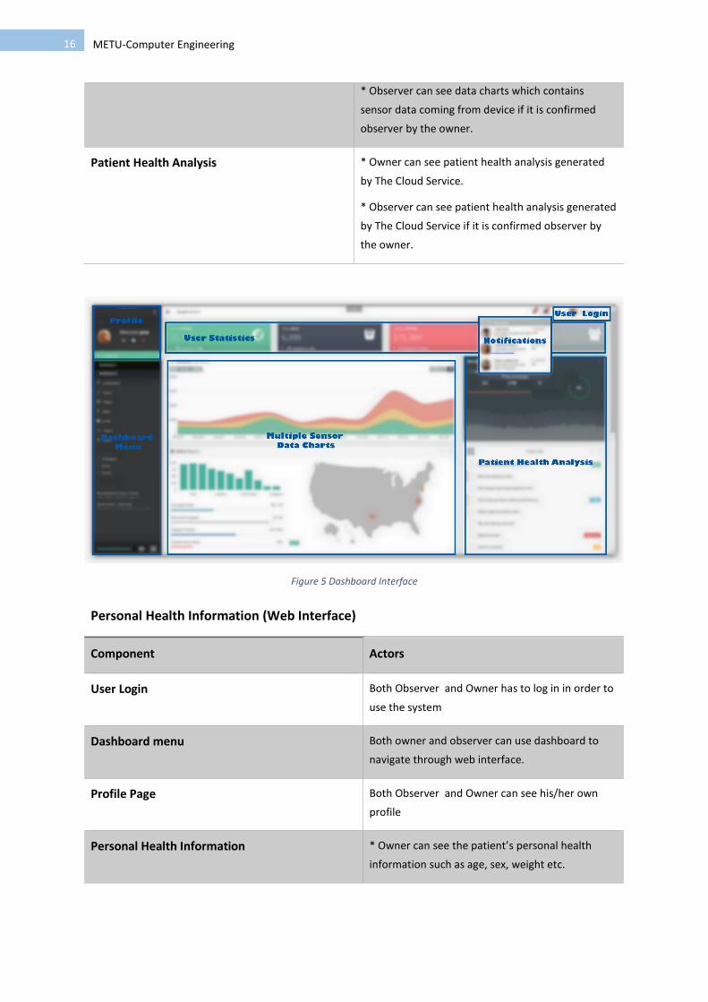
Dashboard (Web Interface)
Component Actor
Dashboard Menu Both owner and observer can use dashboard to
navigate through web interface.
User Statistics * Owner can see user statistics
* Observer can see user statistics if it is confirmed
observer by the owner.
Notifications * Owner can see notifications and alerts
* Observer can see notifications and alerts if it is
confirmed observer by the owner.
Multiple Sensor Data Charts * Owner can see data charts which contains sensor
data coming from device.
16 METU-Computer Engineering
* Observer can see data charts which contains
sensor data coming from device if it is confirmed
observer by the owner.
Patient Health Analysis * Owner can see patient health analysis generated
by The Cloud Service.
* Observer can see patient health analysis generated
by The Cloud Service if it is confirmed observer by
the owner.
Figure 5 Dashboard Interface
Personal Health Information (Web Interface)
Component Actors
User Login Both Observer and Owner has to log in in order to
use the system
Dashboard menu Both owner and observer can use dashboard to
navigate through web interface.
Profile Page Both Observer and Owner can see his/her own
profile
Personal Health Information * Owner can see the patient’s personal health
information such as age, sex, weight etc.

17 METU-Computer Engineering
* Observer can see the patient’s personal health
information such as age, sex, weight if it is
confirmed observer by the owner.
Figure 6 Personal Health Information Interface
Settings Page (Web Interface)
Component Actors
User Login Both Observer and Owner has to log in in order to
use the system
Dashboard menu Both owner and observer can use dashboard to
navigate through web interface.
Profile Page Both Observer and Owner can see his/her own
profile
Settings Page Only owner use settings page which provides an
interface to manage hardware settings remotely.

18 METU-Computer Engineering
Figure 7 Settings Page Interface
Settings Page (Web Interface)
Component Actors
User Login Both Observer and Owner has to log in in order to
use the system
Dashboard menu Both owner and observer can use dashboard to
navigate through web interface.
Profile Page Both Observer and Owner can see his/her own
profile
Observer Manager Only owner can use administration page which
provides an interface to manage observers

19 METU-Computer Engineering
Figure 8 Administration Page Interface
Login Panel (Mobile Phone)
Component Actors
User Login Both Observer and Owner has to log in in order to
use the system

20 METU-Computer Engineering
Figure 9 Login Panel for Phone Application
Dashboard (Mobile Phone)
Component Actor
Dashboard Menu Both owner and observer can use dashboard to
navigate through phone application.
User Statistics * Owner can see user statistics
* Observer can see user statistics if it is confirmed
observer by the owner.
Notifications * Owner can see notifications and alerts
* Observer can see notifications and alerts if it is
confirmed observer by the owner.
Multiple Sensor Data Charts * Owner can see data charts which contains sensor
data coming from device.
* Observer can see data charts which contains
sensor data coming from device if it is confirmed
observer by the owner.

21 METU-Computer Engineering
Figure 10 Dashboard for Phone Application
Personal Health Information (Mobile Phone)
Component Actors
User Login Both Observer and Owner has to log in in order to
use the system
Dashboard menu Both owner and observer can use dashboard to
navigate through mobile application.
User Profile Both Observer and Owner can see his/her own
profile
User Information * Owner can see the patient’s personal health
information such as age, sex, weight etc.
* Observer can see the patient’s personal health
information such as age, sex, weight if it is
confirmed observer by the owner.

22 METU-Computer Engineering
Figure 11 User Profile for Phone Application
3.2. Functional Requirements
3.2.1 Wearable Device Component (Layer 1)
3.2.1.1 Functional Requirement 1
Device carrier user shall be able to enable or disable the embedded system which gathers his/her
data via sensos.
3.2.1.2 Functional Requirement 2
Device carrier user shall be able to activate the panic button on the device itself to trigger emergency.
3.2.1.3 Functional Requirement 3
Embedded device continuously gathers information about the patient via its sensors. It is provided that
the device is enabled.
3.2.1.4 Functional Requirement 4
Embedded device does minimal computation on data which come from several sensors.
3.2.1.5 Functional Requirement 5
Embedded device continuously transfers its data to the upper layer.

23 METU-Computer Engineering
3.2.2 Intermediate Device Component (Layer 2)
3.2.2.1 Functional Requirement 6
Intermediate device generates alerts to its environment if any emergent situation is occurred.
3.2.2.2 Functional Requirement 7
Intermediate device evaluates/analyzes incoming data to decide whether there is an emergency.
3.2.2.3 Functional Requirement 8
Intermediate device transfers evaluated data to the upper layer which is the cloud service(layer 3).
3.2.2.4 Functional Requirement 9
Intermediate device checks if wearable device component(layer 1) is connected and working.
3.2.2.5 Functional Requirement 10
Intermediate device checks whether the Internet connection is available or not.
3.2.2.6 Functional Requirement 11
Intermediate device checks whether the connection with the cloud service(layer 3) is established via the
Internet.
3.2.2.7 Functional Requirement 12
Intermediate device adjusts its LEDs on itself according to the status of connections with other layers and
the Internet.
3.2.2.8 Functional Requirement 13
Intermediate device tags packets to be transmitted to the cloud servers(Layer 3) with the unique device-
user identifier.
3.2.3 Cloud Service Component (Layer 3)
3.2.3.1 Functional Requirement 14
Incoming data from intermediate device layer are stored in the cloud service.
3.2.3.2 Functional Requirement 15
Cloud servers recognize the owner of the incoming data by using the device-user identifier.
3.2.3.3 Functional Requirement 16
Cloud servers perform further analysis on the stored data by correlating predefined health record
information of the patient.
3.2.3.4 Functional Requirement 17
Cloud service layer triggers notifications for web application and corresponding mobile devices if any
emergency situation is detected.

24 METU-Computer Engineering
3.2.3.5 Functional Requirement 18
Cloud service layer shall generate daily reports to be sent to web appliaction and mobile application of
registered users.
3.2.3.6 Functional Requirement 19
Users shall be able to log into the system with his/her credentials.
3.2.3.7 Functional Requirement 20
Users who are logged in to the system shall be able to view patient records.
3.2.3.8 Functional Requirement 21
Logged in users shall be able to display real-time statistics of the patient who wears the wearable device.
3.2.3.9 Functional Requirement 22
Users who are logged in to the system shall be able to register or unregister mobile devices for getting
notifications to them.
3.2.3.10 Functional Requirement 23
Only privileged users(not observers) who are logged in shall be able to change patient's physical health
records.
3.2.3.11 Functional Requirement 24
Authorized users shall be able to filter, sort, search acquired data of the patient.
3.2.3.12 Functional Requirement 25
Privileged user shall view and change settings of sensors. Settings include eneabling/disabling of a specific
sensor and/or adjusting threshold values for a specific measurement.
3.2.3.13 Functional Requirement 26
Logged in users shall be able to view results of analysis.
3.2.4 Mobile Device Component (Layer 4)
3.2.4.1 Functional Requirement 27
Users shall be able to login to the system from mobile platforms with his/her credentials.
3.2.4.2 Functional Requirement 28
Mobile user shall be notified through mobile notification system whenever an emergent situation occurs.
3.2.4.3 Functional Requirement 29
Users who are logged in to the system from mobile shall be able to view patient records.
3.2.4.4 Functional Requirement 30
Users who are logged in to the system from mobile shall be able to view results of analysis.

25 METU-Computer Engineering
3.2.4.5 Functional Requirement 31
Mobile user shall be able to track daily and real-time updates of the patient's condition by using mobile
application.
3.3. Non-Functional Requirements
Non-functional requirements of system can be examined divided into four subsystems which are
wearable device, intermediate device, web server and phone application. Each one of them has their
individual non-functional requirements because of the fact that they operate on different domains and
various conditions.
Major requirements are separated into performance, safety, security requirements subsections. Other
related requirements are explained in software quality subsection.
3.3.1 Performance Requirements
Intensive data collection, transmission and analyze leads to concerns about performance of
the system. Strict timing of sensor data processing shall be satisfied under heavy workloads.
In order to meet performance targets; response time, workload, scalability and platform
issues are needed to be addressed precisely.
System shall be able to operate without falling behind the speed of sensor data flow in 99%
of time. In wearable device part, single wireless transmission module shall be qualified
enough to send all of the sensor data in specified period for each sensor. Microprocessor
located on wearable device shall be able to keep up with this speed and instruct the
transmission module in specified time constraints. Under circumstances which there is no
need to supply immediate awareness, caching of data is an option in intermediate device.
Although caching will be done in intermediate device, an update on the web server is
necessary in each 10 seconds. Rationale behind this comes from studies which indicate 10
seconds is the approximate time limit for keeping user's attention focused. Attention of user
is considered as a requirement because reliability is demonstrated via showing that the
system is responsive. However, in case of emergency, system shall response immediately.
Therefore, data shall not be cached in those situations. 3 seconds of response time is aimed
for web server. Web server shall reflect data changes in at most 10 seconds to keep users
informed. Phone application has the same needs with web server.
Heavy workload term for data gathering is temporarily specified as “up to 10 sensors each
transmitting 100 bits wide chunks of data with one seconds of periods”. So, all subsystems
shall operate without delays, failures and errors considering this peak value. Web server
needs to maintain its responsive state under this workload.
Since number of users are not estimated yet, cloud storage and connection capacity of web
server is not specified and needed to be scalable. More servers can be used and efficient
service can be provided using reverse proxy server in the future.
TCP and UDP protocols are considered for transmission between middleware device and web
server. UDP is a faster protocol comparing to TCP but suffering from lack of reliability. Since
reliability is a topic which cannot be compromised from, TCP is a valid choice. Performance
requirements shall be satisfied using this protocol.

26 METU-Computer Engineering
Transmission between microcontroller and intermediate device shall meet performance
objectives as well as other requirements about data transmission. Bluetooth is a capable
technology considering response time and workload topics.
3.3.2 Safety Requirements
Health-monitoring is a safety critical process by its nature. It is possible that a system failure
causes lack of awareness. In emergent situations, this ends up with fatal injuries and seizures, even
deaths. Furthermore, software logic errors probably causes misinformation. It is required to prevent
miscalculations in analyze part of system. Microcontroller and transmission module on wearable
device shall have a steady voltage level to read and transmit data reliably. Connection to web server is
ought to be established without problems. Aim is to reduce system faults to 0.05% for regular
conditions and to 0% for emergent conditions at any level. It is desired to keep fault propagation
limited with one device. Rapid reboot is required in case of system failures.
Touch sensor shall be used to detect detachments of wearable device and relatives should be
notified. Otherwise, it is probable to cause safety issues explained above.
Origin authentication and data integrity are security-related concerns which also effects
safety of system. Data forgery or prevention causes stated safety requirements to be unsatisfied.
3.3.3 Security Requirements
Data integrity is required to be provided independently for each subsystem to avoid
misinformation. It shall be infeasible to break the system with the purpose of malicious activities.
Security implementations shall be provided within the scope of privacy, integrity and authentication
between every interleaved device in system. Encryption schemes are ought to be employed due to this
concerns.
Medical data shall not be observable by anybody but authorized accounts in web and phone
application. Authorized users shall be identified by patient or relative in charge.
Legal issues and ethics about medical monitoring shall be complied and privacy of patient
shall be respected. Exposure of health data needed to be prevented. Security and privacy
considerations about medical monitoring via wearable devices can be fulfilled with following
explanation: “Security can be preserved using the data encryption, balancing strength of encryption
with power (both in terms of Watts and MIPS), etc. It is important to emphasize that, in the case of
medical monitoring applications, simply wearing the device may disclose to the user's
employer/insurer/acquaintances that the user is suffering from a medical condition” [1]. Bracelet –
lookalike wearable device is a fitting choice for preventing disclosure of medical condition.
3.3.4 Software Quality Requirements
Within the scope of portability considerations, health data gathering shall be performed using a
tiny portable device. Goal is building a compact wearable system which doesn't avoid patient to
perform daily activities. Wireless communication is a primitive requirement for portability. Displaying
health data using phone application is an aid to portability.
Device is needed to allow certain configurations. These are considered as
activating/deactivating sensors, determining measurement periods, selecting variable thresholds for

27 METU-Computer Engineering
those measurements. These configurations shall be understandable by typical users. For which doesn't
able to understand those configurations, best practices shall be supplied.
System shall be reusable if it is needed after unregistration and deactivation. System is activated again
for this sake.
3.3.5 Design Constraints
Since wearable and intermediate devices are ought to be portable, they are prone to hardware
limitations. Cost of device is required to be low for the purpose of creating an affordable system. This
also introduces hardware limitations.
Wearable device has to be supplied with battery, thus power consumption of devices are
needed to be modest values. Future design choices shall be made considering power consumptions.
Sending data through wide area network is a time consuming process especially with
overhead of security requirements. Caching on intermediate device is mandatory. Hard real time
monitoring applications are not feasible because of that.
Wireless transmission modules has limited throughputs. Sensor data structures are needed to
be shrinked in order to be consumed fast enough.
Health data shall not be obtained without user's will. Mandatory regulations shall be take into
account during development of services.
4. Data Model and Description
Three different operation domains exist on system which are domains of Wearable Device, Intermediate
Device, Web Server and Phone Application. Data models on wearable device have a primitive nature, therefore
they are not included on this section of document. Additionally, data models on phone application are not
determined yet, they are also excluded. Since intermediate device and web server are operating on different
domains, data objects and dictionaries are displayed separately.
4.1. Data Description
4.1.1. Data Objects
Class Diagram on intermediate device is demonstrated below:

28 METU-Computer Engineering
Figure 12 Intermediate Device Class Diagram
Class Diagram on web server is demonstrated below:
Figure 13 Web Server Class Diagram

29 METU-Computer Engineering
4.1.2. Data Dictionary
Data dictionary of intermediate device:
Object Descrıptıon
SystemHandler SystemHandler is the major class which initiates tasks of the system and manages all
other handlers. Employs singleton pattern.
Attributes:
systemid: Holds unique identifier of intermediate device. This identifier is required for
authenticated transmission.
ownerid: Holds unique identifier of owner of the intermediate device. This identifier is
required for authenticated transmission.
Functions:
start(): Initiates all of the system tasks
reboot(): Reboots the system in case of failure or configuration change
LogHandler Used to create logs of failures, faults and events.
Functions:
createlog(log): creates log of incident. Takes a Log object as parameter. Log object
holds attributes and message of a log.
BlueHandler BlueHandler is a class which has a single instance that configures and handles listening
part of bluetooth communication.
Attributes:
devicesocket: It keeps the bluetooth socket.
devicemac : Holds unique mac address of paired wearable device.
deviceport: Holds port number of paired wearable device.
Functions:
pair(): Performs pairing operation with the wearable device.
start(): Starts bluetooth handling task which captures sensor data sent via bluetooth.
configure(): Configures mac and port of bluetooth device to be connected.
stop(): Deactivates bluetooth connection.
RelayHandler RelayHandler handles data transmission with the web server. Employs singleton
pattern.
Attributes:

30 METU-Computer Engineering
serversocket: Holds the tcp socket.
serverip: Holds the ip address of the web server.
serverport: Holds the port number of the server.
Functions:
configure(): Configures the RelayHandler object. Transmission periods and server
information can be configured.
start(): Starts periodic transmission task.
stop(): Stops transmission task.
send(): Sends queued data to the web server.
Analyzer An abstract class used for creating diagnosis specific analyzers.
Attributes:
membersensors: holds the list of sensors required for analysis. Analysis task is
performed on specified sensors.
Functions:
start(): Starts analysis task. Task ends up with outcome about urgency of measurement.
AnalyzerFactory A factory class used for creating analyzer objects. These objects are used and exits after
analysis.
Functions:
create(): Creates new analyzer object
Sensor Sensor objects are used for identification of sensors and for input/output operations of
these sensors.
Attributes:
sensorid: Holds the sensor identifier.
sensorname: Holds sensor name which explains duty of sensor.
sensorperiod: Data transmission period of sensor.
isactive: States whether sensor is active or not.
inputqueue: Holds sensor data obtained from wearable device.
outputqueue: Holds already analysed sensor data tagged as regular by analyzer.
urgentqueue: Holds already analysed sensor data tagged as urgent by analyzer.
Functions:
pushinput(input): Pushes item to input queue
getinput(): Gets item from input queue

31 METU-Computer Engineering
pushoutput(): Pushes item to output queue.
getoutput(): Gets item from output queue.
pushurgent(): Pushes item to urgent queue.
geturgent(): Gets item from urgent queue.
SensorData Structure used in order to hold sensor data.
Attributes:
deviceid: Holds unique owner device id.
sensorid: Holds unique sensor identifier
value: Output of sensor measurement
timestamp: A field of SensorData object that keeps measurement time of data.
sequence: sequence number of sensor data.
ConfigParser ConfigParser's duty is to obtain json configurations in order to modify device settings.
JSON files are accepted from web server.
Attributes:
json: A dictionary holds parsed json dictionary.
Functions:
parse(filepath): Parses the json file in given file path.
employsensors(): Extract sensor configurations from json and make configurations
employbluetooth(): Extract bluetooth configurations from json and make
configurations
employanalyzers():Extract analyzer configurations from json and make configurations
Data dictionary of web server:
Object Descrıptıon
User Holds information of typical user and provides primitive operations
Attributes:
username: Holds unique username of user. Username is defined by user.
password: Holds password of user.
userid: Holds unique user identifier. Associate user with corresponding intermediate
device.
Functions:
login(): Used for login operation.

32 METU-Computer Engineering
logout(): Used for logout operation.
viewprofile(): Used to view profile of user.
updateprofile(): Updates profile of user.
Observer Observer is inherited from User class. Holds information of observing accounts and
provides operations for observers.
Attributes:
observing: Holds the list of people who are being observed by the observer user.
Functions:
viewinfo(Owner):
addpatient(Owner): Adds an owner to be observed. Patient (Owner) information is
reachable if the patient authorizes observer by confirming his/her addpatient request.
viewhealthanalysis(Owner): Authorized observers can display health analysis of patient.
Owner Corresponds to the person who is being monitored and observed. Inherited from User
class. Indicates owner of wearable device.
Attributes:
analysislogs: List of previous analysis reports of owner. Authorized observers can see
them.
history: List of previous logs of owner activity. Authorized observers can see them.
Functions:
confirmobserver(): Confirms that applied observer can reach to owner information.
viewhealthinfo(): Displays personal medical information of patient.
updatehealthinfo(): Update personal medical information of patient.
viewhealthanalysis(): Displays health analysis logs to the user.
Device Holds device information of owner. Configurations can be done on intermediate or
wearable device using instances of this class.
Attributes:
deviceid: Unique intermediate device id.
configurations: Current device configurations are kept here.
Functions:
configure(Configuration): Configures the Device object and applies it to actual
intermediate device via data transmission. Transmission periods, analysis settings and
sensor configurations can be changed.
viewconfig(): Displays current configuration of intermediate device.

33 METU-Computer Engineering
Sensor Holds sensor information and measurements belongs to the sensor.
Attributes:
sensorid: Unique identifier of the sensor.
sensorname: Holds sensor name which explains duty of sensor.
sensorperiod: Data transmission period of sensor.
isactive: States whether sensor is active or not.
SensorData Packages data of a single sensor measurement and tags of it.
Attributes:
sensorid: Holds unique sensor identifier
value: Output of sensor measurement
timestamp: A field of SensorData object that keeps measurement time of data.
sequence: sequence number of sensor data.
HealthInfo Personal medical information of owner of the device.
Attributes:
age: Age of owner.
weight: Weight of owner.
height: Height of owner.
diseases: List of diseases owner has.
AnalysisManager Provides an interface for management of analyzers. Responsible for initiating analyzer
tasks.
Functions:
analyze(Owner, Analyzer): Performs specified analysis for user.
Analyzer Abstract object used to create specific classes in order to perform analysis.
Functions:
execute(): executes analysis operation.
Listener Listens communications originated from intermediate devices and associate them with
related objects.
Attributes:
port: Number of listening port.
Functions:

34 METU-Computer Engineering
configure(): Makes configurations on listening operation.
listen(): performs listening operation
DataManager Used to manage sensor data. Acts as an interface between server and database.
Functions:
addsensordata(SensorData, Owner) : Take sensor data and owner of sensor data as
parameter. Checks and adds this data to database.
getsensordata(timestamp,sequence): provides specified sensor data if it exists.
filtersensordata(Query): Execute given query on database. Query is one of the pre-
defined secure sql query objects.
5. Behavioral Model and Description
This section provides the overall behavior of the system. Major events and states are displayed in a state
transition diagram.
5.1. Description for Software Behavior
Project consists of three main components that have their own software designs and states.
Components are sensor hardware, intermediate device and web server and data flows through those,
respectively. Web server also communicates with a web application and mobile application when
requested, but those are for presentation purposes and does not included in state transition diagram for
sake of simplicity. Detailed behaviors of software of each component were presented in earlier chapters.
5.2. State Transition Diagrams
The state transition diagram in Figure 14 shows all the states, triggers and conditions for each transition
and related events.

35 METU-Computer Engineering
Figure 14 State Transtion Diagram
Initially, all components must be turned on for a healthy operation.
Sensors hardware starts gathering information and sending them as soon as possible after it was turned on.
There is no significant state change, this component periodically sends data to upper component.
Intermediate device starts with ready state to accept data, after booting and initialization. It has its own
configuration of transmission rates, caching and analyzing of incoming data. This part will mostly stay at ready
state, and when other it transits to other states, it will return back to ready state after triggering external
actions such as analyzing, caching and delivering data.

36 METU-Computer Engineering
Web Server's design is similar to Intermediate device, but this component has much more resources and more
responsibility. It will have a concurrent design, but in chart, we presented a simpler overall design. Incoming
data from intermediate device is processed, stored and necessary actions such as notifications are taken in
turn. Similarly, this is a server design supposed to serve multiple clients both from input side (i.e. data from
intermediate device) and output side (notifications), therefore, similar to Intermediate device, this component
will be mostly at Ready state to avoid misses, and directs the workload to channels (i.e. threads or processes)
to return back listening.
6. Planning
6.1. Team Structure
We periodically meet with Dr. Attila Özgit and Dr. Onur Tolga Şehitoğlu for consultancy. We roughly shared
the work since our project has multiple components. Our members and each of their focus’ is explained below:
Gökçen Nurlu – Developer, Mobile Side
Halil Burak Noyan – Developer, Hardware Module
Can Carlak – Developer, Sensors and MCU module
Mehmet Cüneyit Kiriş – Developer, Server side development
Despite this division of labor, all members of our group is following every update of other member’s works
and we are trying to maintain a balance so that everyone would contribute to every part of the project equally.
6.2. Estimated Schedule
The project is planned to be finished by June 2014. We are going to make our progress in 4 main phases.
Phases and tasks inside are described in Figure 15 .

37 METU-Computer Engineering
Figure 15 Estimated Schedule

38 METU-Computer Engineering
6.3. Process Model
We will apply agile model for our health monitoring system so that system can respond quickly to changing
requirements without excessive rework. Agile method is based on an iterative approach, each iteration
involves planning, requirements analysis, design, implementation, testing. Each iteration takes approximately
four weeks. After we implement the initial version of project, then our project’s development will be continued
according to accuracy of sensor data, additional available sensors, battery performance, accuracy of analysis of
data and performance of whole system under heavy use.
7. Conclusion
This Software Requirement Specification document is a summary is basically prepared as a guideline for the
journey of a byte. A byte possibly consist of most crucial information about the very own life of an individual.
Mandatories, obstacles, paths and precautions of the travel of the byte is explained in detail. Requirements are
listed unambiguously and clearly; starting from birth of the byte, during evolution of it and ending on personal
devices of concerned people in order to save lives.
This Software Requirement Specification document is prepared to give requirement details of the project
“Cloud Doctor/Health Monitoring System”. The detailed functional and nonfunctional requirements, system,
user, software and hardware interfaces, data and behavioral model are stated in an extended outline. This
document will be helpful at constituting a basis for design and development of the system to be developed.
Figure 16 Process Model
39 METU-Computer Engineering
A
accelerometer · 9
administration page · 9, 19
agile · 40
B
battery performance · 40
C
caretakers · 6
Cloud Doctor · 1, 2, 14, 15, 40
Cloud service · 10, 25
communication protocols · 9
D
Dashboard · 16, 17, 18, 19, 21, 22
Data integrity · 27
data model · 7
H
health analysis · 11, 13, 14, 17, 33, 34
health monitoring system · 6, 40
Humidity · 10
I
Intermediate device · 10, 24, 37, 38
L
Login Panel · 15, 16, 20, 21
M
Microcontroller · 7, 27
module · 8, 10, 26, 27, 38
N
network · 14, 28
Notifications · 12, 14, 16, 21
P
patient · 6, 7, 8, 9, 11, 12, 13, 14, 17, 18, 22, 23, 25, 26,
27, 28
personal health · 9, 17, 18, 22
Phone Application · 21, 22, 23
Pulse · 10
S
Schedule · 38
sensor · 6, 7, 8, 9, 10, 11, 13, 14, 15, 16, 21, 25, 26, 27,
40
Settings Page · 5, 18, 19
software designs · 36
T
TCP · 11, 27
Temperature · 9
U
user interfaces · 15
User Login · 17, 18, 19, 20, 22
W
Wearable device · 10, 28
wearable system · 28
Web Interface · 15, 16, 17, 18, 19
web server · 7, 8, 26, 27
Wireless · 10, 28