clinton, unit 1, supplemental information supporting the
TRANSCRIPT
AmerGen..AmerGen Energy Company, LLCClinton Power StationR R. 3 Box 228Clinton, IL 61727-9351
An Exelon/British EneTgy Company
RS-03-069
March 28, 2003
U. S. Nuclear Regulatory CommissionATTN: Document Control DeskWashington, DC 20555-0001
Clinton Power Station, Unit 1Facility Operating License No. NPF-62NRC Docket No 50-461
Subject:
References:
Supplemental Information Supporting the License Amendment Request toPermit Inclined Fuel Transfer System Blind Flange Removal During PowerOperations
(1) Letter from J. M. Heffley (AmerGen Energy Company, LLC) to U.S. NRC,"Request for License Amendment to Technical Specifications to PermitInclined Fuel Transfer System Blind Flange Removal During PowerOperations," dated April 2, 2001
(2) Letter from K. R. Jury (Exelon Generation Company, LLC) to U.S. NRC,"Response to Request for Additional Information Regarding Risk Aspects ofInclined Fuel Transfer System License Amendment Request for ClintonPower Station," dated January 15, 2002
(3) Letter from T. W. Simpkin (Exelon Generation Company, LLC) to U. S. NRC,"Additional Information Supporting the License Amendment Request toPermit Inclined Fuel Transfer System Blind Flange Removal During PowerOperations," dated August 23, 2002
In Reference 1, AmerGen Energy Company (AmerGen), LLC submitted a request for changesto the Facility Operating License No. NPF-62 and Appendix A to the Facility OperatingLicense, Technical Specifications (TS), for Clinton Power Station (CPS) to permit Inclined FuelTransfer System (IFTS) blind flange removal during power operations. The proposed changesin Reference 1 requested the addition of a conditional note before the Actions for TS Section3.6.1.3, "Primary Containment Isolation Valves (PCIVs)," which will identify the controlsrequired for allowing the IFTS blind flange to be removed during Modes 1, 2, or 3. Additionalinformation concerning the risk aspects of the proposed change was provided in Reference 2.The NRC requested additional follow-up information regarding the information provided in theReferences 1 and 2. Reference 3 provided the requested information.

March 28, 2003U. S. Nuclear Regulatory CommissionPage 2
In a conference call on September 5, 2002, the NRC requested supplementalinformation in support of their review of this request. Specifically, the NRC requestedadditional information concerning the ultimate pressure capacity and seismic capabilitiesof the IFTS components. In addition, in a follow-up conference call on February 5, 2003,the NRC requested clarification on the ability to perform manual actions in thecontainment following a reactor scram and the seismic qualification of the IFTS when theblind flange is in the unbolted configuration. Attachment 2 to this letter provides therequested information.
The evaluation supporting this request for information has resulted in a need to add aconditional note to TS Section 3.6.1.1, "Primary Containment - Operating," and itsassociated Bases. These proposed changes are in addition to those changes proposedin Reference 1. Attachment 3 provides the marked-up TS pages and Bases pages (forinformation only) reflecting the revised wording. The information supporting a NoSignificant Hazards Consideration provided in Reference 1 has also been revised toaddress the changes proposed in Attachment 3 to this letter. The revised No SignificantHazards Consideration is provided in Attachment 4.
Should you have any questions related to this information, please contact Mr. Timothy A.Byam at (630) 657-2804.
Sincerely,
gqt k J~afKeith R. JuryDirector - Licensing and Regulatory AffairsMid-West Regional Operating GroupAmerGen Energy Company, LLC
Attachments:
1. Affidavit2. Supplemental Information Supporting the License Amendment Request to Permit
Inclined Fuel Transfer System Blind Flange Removal During Power Operations3. Markup of Proposed Technical Specification Changes and Bases Changes (for
information only)4. Information Supporting a Finding of No Significant Hazards Consideration
cc: Regional Administrator- NRC Region IIINRC Project Manager, NRR - Clinton Power StationNRC Senior Resident Inspector - Clinton Power StationOffice of Nuclear Facility Safety - Illinois Department of Nuclear Safety

STATE OF ILLINOIS )
COUNTY OF DUPAGE
IN THE MATTER OF
)
AMERGEN ENERGY COMPANY, LLC
CLINTON POWER STATION, UNIT 1
) Docket Number
) 50-461
SUBJECT: Supplemental Information Supporting the License AmendmentRequest to Permit Inclined Fuel Transfer System Blind FlangeRemoval During Power Operations
AFFIDAVIT
I affirm that the content of this transmittal is true and correct to the best of myknowledge, information and belief.
Keith R. JuryDirector - Licensing and Regulatory AffairsMid-West Regional Operating GroupAmerGen Energy Company, LLC
Subscribed and sworn to before me, a Notary Public in and
for the State above named, this
kucil�- ��' 200:
,64 day of
3.
I Notary(kul
51
T ffCA L SA L"&AA
I rVV7VVTVVVVT"7VVV Tvirm
ATTACHMENT 2
Supplemental Information Supporting the License Amendment Request toPermit Inclined Fuel Transfer System Blind Flange Removal During Power
Operations
IFTS Ultimate Pressure Capacity Evaluation
An engineering evaluation was performed to document the impact of a beyond-design-basis containment pressure on the pressure capacity of the Inclined Fuel TransferSystem (IFTS) components and piping when the blind flange is removed. Thisevaluation was performed to assess the ability of selected IFTS components to maintaintheir pressure retention capability for a beyond-design-basis containment pressure of 63psig with the blind flange removed. This 63 psig value corresponds to the containmentultimate capacity as described in the Clinton Power Station (CPS) Updated SafetyAnalysis Report (USAR), Section 3.8.1.4.8. The components that were evaluatedincluded the transfer tube (1 F42-DO01), the bellows (1 F42-GO01, 1 F42-G002), theexpansion joints (1 F42-D300, 1 F42-D301), the upper and bottom gate valves (1 F42-F002, 1 F42-F004), the drain line (1 FH07A) and the drain line isolation valves (1 F42-F003 and 1 F42-F301). The evaluation was limited to components that would beimpacted by removal of the blind flange. It did not evaluate the impact on componentsfor which removal of the blind flange would not impact the pressure that the componentwould experience.
1) 1F42D001The design pressure of the containment isolation assembly portion of the IFTStransfer tube is 40 psig (Reference 1). Based on a comparison of the I FTS tubethickness and material type against the material properties of the containmentisolation assembly, a 40 psig design pressure is assumed for the IFTS tube. Thiscomparison is necessitated because the design specification does not list a specificdesign pressure. The structural and seismic analysis for the IFTS tube, asdocumented in Reference 1, does not use 40 psig but assumes lower internalpressures dependent on the tube elevation. Review of the analysis shows there ismargin between the calculated and allowable stresses. In addition, the analysis isbased on material allowable stresses that are considerably less than the specifiedmaterial yield strength. For example, at room temperature the material yield strengthis 30 ksi and the material allowable stresses are approximately 19 ksi. There wouldbe additional margin between the specified minimum material yield and ultimatestrengths. Also, there are generally margins available between the minimumrequired and actual material properties. As a result, it is concluded that the pressureretaining capacity will be maintained for beyond-design-basis containment pressuresof 63 psig with the IFTS blind flange removed.
2) 1 F42-G001, lF42-G002, lF42-D301Removal of the IFTS flange does not impact the pressure load on these items. 1 F42-G001, the expansion bellows, is part of the containment pressure boundary evenwith the IFTS blind flange closed. 1F42-G002 and 1F42-D301, expansion bellowsand expansion joint respectively, are on sleeves surrounding the IFTS tube andwould not be exposed to containment atmosphere regardless of the position of theIFTS blind flange. Therefore, these components were not evaluated for beyond-design-basis pressures.
Page 1 of 9

ATTACHMENT 2
Supplemental Information Supporting the License Amendment Request toPermit Inclined Fuel Transfer System Blind Flange Removal During Power
Operations
3) 1 F42-D300The centerline elevation of the 1 F42-D300 expansion joint is approximately 755'-7"(i.e., 755.58 ft). The maximum upper pool water elevation is less than the elevationof the floor, which is 828'-3" (i.e., 828.25 ft). Assuming the maximum density ofwater of 62.4 Ib/ft3, the potential hydrostatic pressure at this component is 31.5 psig[(828.25 ft - 755.58 ft)*62.4 lb/ft3I(144in2/ft2)]. Adding 63 psig for beyond-design-basis containment pressure results in a pressure of 94.5 psig. The design pressurefor the expansion joint is 50 psig (Reference 2). Catastrophic pressure retentionfailure at 94.5 psig would not be expected, however, for the following reasons.
This expansion joint is a "Tied Universal Bellows" manufactured by Pathway Bellows.Reference 3 identifies that the manufacturer's pressure test would have been 1.5times the design pressure, or 75 psig. The test pressure would not have beenallowed to exceed the material yield strength. The pressure retaining components ofthe bellows assembly (i.e., the bellows and connected piping) are constructed ofASTM A240, Type 304 and ASTM A312, Type P304 materials, respectively(Reference 2). Both materials have specified minimum yield and ultimate strengthsof 30 ksi and 75 ksi, respectively. The design would be based on yield strength. Asafety factor is typically applied to design and the actual material strengths normallyexceed minimum specification requirements.
Pathway Bellows was contacted to provide an estimate of the pressure retainingcapacity of the bellows. They performed an informal evaluation and concluded thatwhen a 2.25 safety factor is applied, the bellows could withstand a pressure of 117psig. In addition, it was concluded that the associated hardware is capable ofwithstanding a pressure of 117 psig and will remain within allowable stress limits atthis pressure.
Engineering judgment, based on the above discussion, concludes that I F42-D300will maintain its pressure retention ability for beyond-design-basis containmentpressures as high as 63 psig.
4) 1 F42-F002, F42-F0041 F42-F002 and 1 F42-F004 are double disc gate valves manufactured by AnchorDarling (Reference 5). They have ANSI Class 150# flanges welded to their inletsand outlets. Their specified primary service rating is 75 psig and their specifieddesign pressure is 50 psig (Reference 4). These valves were hydrostatic tested at113 psig (Reference 5). The hydrostatic test pressure would not have been allowedto exceed the material yield strength. The outlet elevation of the lower of the twovalves is 728'1 1" (i.e., 728.92 ft). Assuming the maximum water density of 62.4lb/ft3, the hydrostatic head pressure would be 43 psig [(828.25 ft - 728.92 ft)*62.4lb/ft3/(144in2/ft2)]. The maximum pressure at the valve for a beyond-design-basiscontainment pressure of 63 psig (i.e., 63 psig + 43 psig equals 106 psig) would beless than the hydrostatic test pressure (i.e., 113 psig). The flange material is A351,Gr. CF8M (Reference 5). The ANSI allowable pressure for the flanges at 2000 F is240 psig. As a result, it is judged that these valves will maintain their pressure
Page 2 of 9

ATTACHMENT 2
Supplemental Information Supporting the License Amendment Request toPermit Inclined Fuel Transfer System Blind Flange Removal During Power
Operations
retaining integrity if they are subjected to a beyond-design-basis containmentpressure of 63 psig.
5) 1FH07AThe design pressure for this line is 100 psig. The lowest piping elevation is 752'-3"(i.e., 752.25 ft). Assuming the maximum water density of 62.4 lb/ft3, the hydrostaticpressure would be 33 psig [(828.25 ft - 752.25 ft)*62.4 lb/ft3/(l 44in2/ft2)]. Adding 63psig for beyond-design-basis containment pressure results in a total pressure of 96psig. As a result, a beyond-design-basis containment pressure of 63 psig does notrepresent a pressure retention concern for this drain line.
6) 1 F42-F0031 F42-F003 is a Hills-McCanna 4-inch ball valve with a specified 50 psig processdesign pressure (References 6 and 7). The design specification requires the valve tobe a 150# pressure class valve per ANSI B16.5 (Reference 6). The constructionmaterial for the body and bonnet is ASTM 351, Gr. CF8M (Reference 7). Theallowable operating pressure for ANSI 150# class valves constructed from thismaterial at 2000 F is 240 psig. The valve elevation is 752'-3" (i.e., 752.25 ft).Assuming the maximum density of water of 62.4 lb/ft3 and maximum possible upperpool level, the hydrostatic head pressure is 33 psig [(828.25 ft - 752.25 ft)*62.4lb/ft3/(144in2/ft2)]. Adding 63 psig for beyond-design-basis containment pressureresults in a pressure of 96 psig. This is much less than the ANSI allowable operatingpressure of 240 psig. As a result, a beyond-design-basis containment pressure of 63psig does not represent a pressure retention concern for this valve.
7) 1 F42-F301The applicable piping design table for 1 F42-F301 requires this valve to be an ANSIClass 150# valve. The valve material is ASTM A351 CF8M stainless steel(Reference 8). The allowable pressure at a temperature of 2000 F is 240 psig. Thevalve elevation is 752'-3" (i.e., 752.25 ft). Assuming the maximum density of waterof 62.4 Ib/ft3 and maximum possible upper pool level, the hydrostatic head pressureis 33 psig [(828.25 ft - 752.25 ft)*62.4 lb/ft3/(144in2/ft2)]. Adding 63 psig for beyond-design-basis containment pressure results in a pressure of 96 psig. This is muchless than the ANSI allowable operating pressure of 240 psig. As a result, a beyond-design-basis containment pressure of 63 psig does not represent a pressureretention concern for this valve.
In summary, it is expected that the pressure retention capability of the IFTS componentsincluded in this evaluation will be maintained during beyond-design-basis events inwhich the IFTS blind flange is removed and the containment pressure reaches 63 psig.
IFTS Seismic Capacity Evaluation
Rotation of the IFTS spectacle flange to the open position does not significantly changethe seismic characteristics of the IFTS tube, however it does change the pressure-retaining boundary for the containment. Where the spectacle flange is normally the
Page 3 of 9

ATTACHMENT 2
Supplemental Information Supporting the License Amendment Request toPermit Inclined Fuel Transfer System Blind Flange Removal During Power
Operations
pressure boundary for the containment, the IFTS tube, drain line piping and valveswould become the pressure boundary with the IFTS flange in the open position. Thischange in containment boundary does not make an appreciable difference in the seismiccapacity of the containment as discussed below.
CPS did not utilize a seismic PRA analysis to determine the seismic fragility of thecontainment. Instead, for the Individual Plant Examination for External Events (IPEEE),CPS used the Seismic Margins Assessment (SMA) approach. In this approach theseismic capacity of a set of safe shutdown equipment was confirmed to meet or exceedthe Seismic Margins Earthquake (SME) of 0.3 g peak ground acceleration. The SMAconcluded that the containment and components are seismically rugged when analyzedfor the SME. The SMA determined that, because of conservatisms used in the seismicdesign approach, the 0.25 g peak ground acceleration Safe Shutdown Earthquake(SSE), as used for design, would bound the SME of 0.3 g. This means that structuresand components designed for the CPS SSE would also be capable of withstanding theSME. It is therefore concluded that the containment has a High Confidence of a LowProbability of Failure (HCLPF) of at least 0.3 g.
Adding the IFTS tube, drain piping and valves to the containment pressure boundaryshould not reduce the containment seismic capacity below a HCLPF of 0.3 g. This isbecause the IFTS tube and drain piping are essentially piping systems. Piping systemsare inherently rugged as demonstrated by actual performance of above ground, weldedsteel piping in industrial plants that have experienced large earthquakes. The SMAapproach recognizes this. When reviewing piping systems for the SMA, the majorconcern is that the piping systems retain adequate flexibility to accommodate seismicmotions. In particular, there should be sufficient flexibility to deal with differential motionof pipe anchorage points. Seismic inertial effects in welded steel piping systems are notconsidered to be primary failure initiators. A review of the seismic design for the IFTStube, drain line piping and valves confirms this as is discussed below.
1) 1 F42-DOOIThe IFTS tube (i.e., 1 F42-DO01) was seismically analyzed in Reference 1. Theanalysis shows substantial margin between the calculated and allowable stresses.In addition, the referenced analysis is based on ASME code allowable stressesbased on material yield strength. There is margin between the minimum yield andultimate strength requirements for the material. In addition, there is generally somemargin between the actual and minimum required material strength. As a result, it isjudged that the IFTS tube will maintain pressure-retaining integrity when the SME isapplied.
2) 1 F42-G001, 1 F42-G002, 1F42-D301Rotation of the IFTS flange does not impact the pressure on these items. 1 F42-G001, the expansion bellows, is part of the containment pressure boundary evenwith the IFTS blind flange closed. 1F42-G002 and 1F42-D301, expansion bellowsand expansion joint respectively, are on sleeves surrounding the IFTS tube andwould not be exposed to containment atmosphere regardless of the position of the
Page 4 of 9

ATTACHMENT 2
Supplemental Information Supporting the License Amendment Request toPermit Inclined Fuel Transfer System Blind Flange Removal During Power
Operations
IFTS blind flange. Therefore, these items produce no new seismic capacities for thecontainment boundary with the IFTS flange open.
3) 1F42-D3001 F42-D300 (i.e., expansion joint) is a Tied Universal Bellows manufactured byPathway Bellows. The bellows material is ASTM A240, Type 304. The seismicloading on the bellows was evaluated (Reference 9) and the loading anddisplacement were found to be within vendor specified requirements. The minimumspecified yield and minimum specified ultimate strengths for this material are 30 ksiand 75 ksi, respectively. The bellows design would be based on yield strength.Also, these bellows were qualified to operate at temperatures as high as 700° F.Review of ASME Section III, Division 1 Subsection NA, Appendix I for this type ofmaterial shows that the allowable yield strength at 2000 F is significantly higher thanat 7000 F. In addition, a safety factor is typically applied to design and the actualmaterial strengths normally exceed minimum specification requirements. Based onengineering judgment, it is concluded that 1 F42-D300 will maintain its pressureretaining integrity if the SME is applied.
4) 1 F42-F002, 1 F42-F004The upper and lower gate valves, 1 F42-F002 and 1 F42-F004 respectively, areisolation valves on the IFTS tube. They are more robust than the IFTS tube pipingitself. Operators on these valves are not unusually long or massive relative to thesize of the IFTS tube. Therefore, the operators will not apply excessive bendingloads to the valves or IFTS tube. Based on the above, these valves do not constitutea weakness in the IFTS tube seismic capacity.
5) 1 FH07A1FH07A, the IFTS tube drain line, was seismically analyzed in References 9 and 10.The Reference 9 analysis covered the portion of piping from the IFTS tube to wherethe drain line is embedded into the wall. The remainder of the line is evaluated inReference 10 and includes the drain line isolation valves 1F42-F003 and 1F42-F301.
Review of these analyses shows there is substantial margin between the calculatedand allowable stresses for the portion of piping of interest. In addition, theseanalyses are based on allowable stresses and material yield strength requirements.There is margin between the minimum yield strength and ultimate strengthrequirements. In addition, there is generally margin between minimum materialrequirements and the actual material strength. Based on this discussion it isconcluded that the drain piping will maintain its pressure retention capability if theSME is applied.
6) 1 F42-F003Drain line isolation valve 1 F42-F003 is a Hills-McCanna 4-inch ball valve and iscompact and seismically rugged. It has an ANSI Class rating of 150# (References 6and 7). Reference 10 shows that the resultant seismic accelerations based on thestandard seismic response spectra for this valve are small (< 1.0 g). Based on thevalve type design and the low seismic accelerations using the standard response
Page 5 of 9

ATTACHMENT 2
Supplemental Information Supporting the License Amendment Request toPermit Inclined Fuel Transfer System Blind Flange Removal During Power
Operations
spectra, it is concluded that this valve will maintain its pressure retaining capability ifthe SME is applied.
7) 1 F42-F301Drain line isolation valve 1 F42-F301 is a manually operated plug valve (Reference 8)and is compact and seismically rugged. The valve is an ANSI Class 150# valve.Reference 10 shows that the resultant seismic accelerations at this valve, based onthe standard seismic response spectra are small (< 1.0 g). Based on the valve typedesign and the low seismic accelerations using the standard response spectra, it isconcluded that this valve will maintain its pressure retaining capability if the SME isapplied.
Based on the above discussions, it is concluded that the IFTS tube, drain line piping andvalves have adequate capacity to withstand inertial seismic loads.
A review of the IFTS tube and attached drain piping determined that although the systemis adequately supported, sufficient flexibility exists to accommodate seismic motions ofthe IFTS tube and drain lines. This is accomplished though the use of bellows andpiping runs with bends in it.
Based on the above, it can be concluded that the containment's seismic capacity withthe IFTS blind flange open is adequate to accommodate the SME of 0.3 g peak groundacceleration.
Manual Actions to Isolate the IFTS Transfer Tube
In Reference 11, AmerGen provided a description of the manual actions required toremove and replace the blind flange during a Loss of Coolant Accident (LOCA). In theevent of a LOCA, reinstallation of the blind flange would require a number of manualactions. Most of these actions require access to the containment. As documented in theresponse to Question 1 in Reference 11, a LOCA would result in elevated temperaturesand pressures in the containment. For example, during a small break LOCA with bypassof the suppression pool, the area of the containment where the IFTS blind flange islocated would become inaccessible for a period of time. As a result, rotating the flangeduring these conditions would not be feasible. The high level of water above the lowerend of the IFTS tube effectively seals the tube and precludes it from becoming a leakpath up to the 9 psig pressure associated with the large break LOCA. As described inReference 11, if the IFTS tube bottom valve is open at the initiation of a LOCA, the IFTSoperator will take action in accordance with CPS procedure 3702.01, 'Inclined FuelTransfer System (IFTS)," to isolate the bottom valve using the hydraulic actuator. Thiswill ensure isolation of the IFTS tube.
Reference 11 also states that if the fuel transfer carriage or cables are part way throughthe open valve, the operator will raise the carriage to a point above the fill/drain positionand then close the valve. In a LOCA with offsite power available all these actions can beperformed from the IFTS control panel in the Fuel Building. However, in the event of a
Page 6 of 9
ATTACHMENT 2
Supplemental Information Supporting the License Amendment Request toPermit Inclined Fuel Transfer System Blind Flange Removal During Power
Operations
loss of offsite power (LOOP) the power to the IFTS control panel is lost. Therefore,contingency actions will be provided in approved station procedures to enable themanual closure of IFTS bottom gate valve. These actions are taken from thecontainment and the fuel building.
CPS procedure 4100.01, "Reactor Scram," has an immediate operator action thatrequires evacuation of the containment for any scram. If a LOOP were to occur withouta scram, a containment evacuation may not be required. However, if a scram doesoccur then the containment would be evacuated. This will make performance of anymanual actions in the containment impractical. The reactor scram procedure states thatcontrolled re-entry into the containment will be allowed with Radiation Protection (RP)concurrence. RP will be directed to give priority to a team of persons to work onrestoring the IFTS penetration and will support re-entry into the containment as soon ascontainment conditions allow. All of these actions will ensure that the IFTS tube isisolated as quickly as possible following a LOCA.
IFTS Blind Flange Unbolted Configuration
The manual actions required to remove the blind flange and replace the flange with agasketed ring assembly are described in Reference 11. The actions required to reinstallthe blind flange are also described in Reference 11. The actions required for removingor reinstalling the blind flange are similar. These actions include loosening all the spoolbolts, removing 11 of the spool bolts and the associated locking plates, and then using ahydraulic hand pump to compress the pipe reducing spool allowing the flange to berotated. Once the flange is rotated, the spool bolts and locking plates are replaced andall the spool bolts are tightened. This is a temporary condition in which the unboltedconfiguration is not formally analyzed for all accident scenarios. The risk is to thebellows assembly, as exact seismic displacements are not quantified when the blindflange bolts are removed. While damage to the bellows may result from a seismic eventthe containment integrity will not be affected. Failure of the bellows assembly wouldresult in a potential bypass of the containment. The containment isolation function willbe achieved by taking credit for the fact that the IFTS transfer tube terminates deep inthe fuel building transfer pool. In addition, when the blind flange is rotated the bottomgate valve and drain valves are closed providing containment isolation. The pressure-retaining boundary for the containment will be the IFTS tube, drain line piping and valvesduring this period just as they are during the period when the blind flange has beenremoved.
As a result of the seismically indeterminate condition of the IFTS while the blind flange isunbolted, it has been determined that the time the system is in this condition will belimited. This condition is expected to exist for no more than a cumulative total of 12hours per cycle during Modes 1, 2, or 3. Based on the above, it has been determinedthat the containment must be considered to be inoperable in this configuration until theflange bolts are properly tensioned. Therefore, this configuration would require entryinto the Actions of Limiting Condition for Operation (LCO) 3.6.1.1, "PrimaryContainment." To address this issue, a new note is proposed for inclusion into the
Page 7 of 9

ATTACHMENT 2
Supplemental Information Supporting the License Amendment Request toPermit Inclined Fuel Transfer System Blind Flange Removal During Power
Operations
Actions for LCO 3.6.1.1. The new note states that the "Applicable Conditions andRequired Actions are not required to be entered for the Inclined Fuel Transfer System(IFTS) penetration for up to 12 hours per cycle when the IFTS blind flange is unbolted."This note provides a 12 hour delay during removal and reinstallation of the blind flangebefore the TS Actions are required to be entered when the IFTS blind flange is unboltedin Modes 1, 2, or 3. This is required to conservatively limit the seismic risk associatedwith the unbolted IFTS flange, yet provides adequate time to complete flange rotation.The cumulative time the IFTS is in the unbolted condition in Modes 1, 2, or 3 will betracked by procedure and the TS Bases will be revised to note that this condition will betracked.
Attachment 3 provides a markup of TS Section 3.6.1.1 to reflect the proposed changesas described above. A marked-up copy of the affected pages from the current TS Basesis also provided in Attachment 3 for information only. Following NRC approval of thisrequest, the CPS TS Bases, in accordance with the TS Bases Control Program of TSSection 5.5.11, will be revised to incorporate the changes described above. Theproposed changes provided in Attachment 3 are in addition to those changes that werepreviously provided in Reference 12. As a result of the additional changes to the CPSTS proposed in this submittal, the original No Significant Hazards Considerationprovided in Reference 12 has been revised. The revised No Significant HazardsConsideration is included in Attachment 4. The proposed changes do not impact theenvironmental consideration provided in Reference 12.
References
1. Seismic Qualification Binder SQ-CL705, "Dynamic Qualification of Inclined FuelTransfer Tube Tag No. 1 F42-DO01 "
2. Pathway Bellows Drawing Al -20-003, Revision A
3. Pathway Bellows Expansion Joint Design Manual, Manual 177G, Copyright January,1977
4. GE Purchase Specifications 21A3512, "Gate Valve and Operator," Revision 2 and21A2080, "Valve, Gate, (Manual)," Revision 2
5. Anchor Darling Drawing Numbers 93-14388, Revision F and 93-14389, Revision E
6. GE Purchase Specification 21A3516, "Valve, Drain (Motor Operated)," Revision 1
7. VTIP Binder K2801-0067, Revision 5
8. Drawing NP3861-C, Vendor Code T340
9. Clinton Power Station Calculation IP-M-602, "Piping Stress Report for Subsystem1 FH-01," Revision 0
Page 8 of 9

ATTACHMENT 2
Supplemental Information Supporting the License Amendment Request toPermit Inclined Fuel Transfer System Blind Flange Removal During Power
Operations
10. Calculation 025246, "Piping Stress Report for Subsystem 1 FH02"
11. Letter from T. W. Simpkin to U. S. NRC, "Additional Information Supporting theLicense Amendment Request to Permit Inclined Fuel Transfer System Blind Flangeremoval during Power Operations," dated August 23, 2002
12. Letter from J. M. Heffley to U. S. NRC, "Request for Amendment to TechnicalSpecifications to Permit Inclined Fuel Transfer System Blind Flange Removal DuringPower Operations," dated April 2, 2001
Page 9 of 9
ATTACHMENT 3
MARKUP OF PROPOSEDTECHNICAL SPECIFICATION CHANGES
ANDBASES CHANGES (FOR INFORMATION ONLY)
Revised TS Paqe
3.6-1
Revised Bases Pacqe (For Information Only)
B 3.6-3
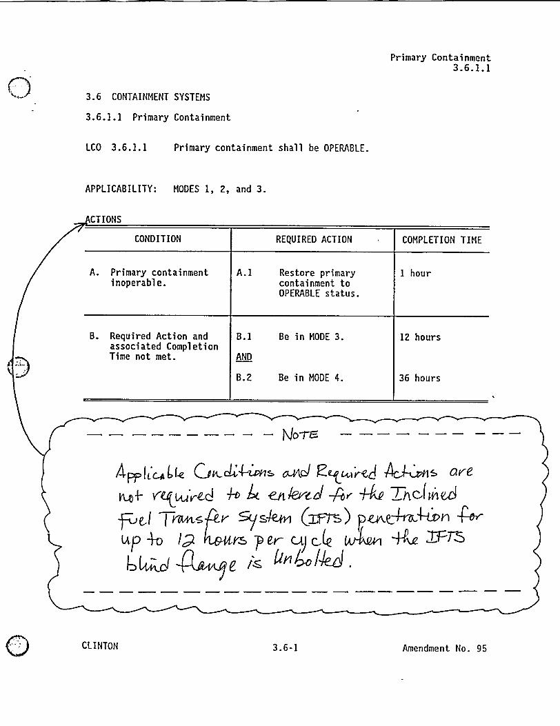
Primary Containment3.6.1.1
3.6 CONTAINMENT SYSTEMS
3.6.1.1 Primary Containment
LCO 3.6.1.1 Primary containment shall be OPERABLE.
APPLICABILITY: MODES 1, 2, and 3.
--ACTIONS
CONDITION REQUIRED ACTION COMPLETION TIME
A. Primary containment A.1 Restore primary 1 hourinoperable. containment to
OPERABLE status.
B. Required Action and B.1 Be in MODE 3. 12 hoursassociated CompletionTime not met. AND
B.2 Be in MODE 4. 36 hours
/Nj tt'ctle QchA-ios andJ qCretJ Age&~s revei4- 4At Atsd AD h al -/' Y-d AI Tj4 )-FweJ Tyts P- 5;(sk (IF) pzA0,-,4tf X t0u=~p +0 1<2 Ir Cr) Ce U m +K 4
() b a e/s -4'H., - _ _ _
,S
CLINTON 3 .6-1 Amendment No. 95

Primary ContainmentB 3.6.1.1
BASES (continued)
LCO
IPrimary containment OPERABILITY is maintained by limitingleakage to c 1.0 La) except prior to the first startup afterperforming a required Primary Containment Leakage RateTesting Program leakage test. At this time, applicableleakage limits must be met. Compliance with this LCO willensure a primary containment configuration, includingequipment hatches, that is structurally sound and that willlimit leakage to those leakage rates assumed in the safetyanalysis. Individual leakage rates specified for theprimary containment air locks are addressed in LCO 3.6.1.2.
I
I
I
ii
i
APPLICABILITY In MODES 1, 2, and 3, a DBA could cause a release ofradioactive material to primary containment. In otheroperational conditions, events which could cause a releaseof radioactive material to primary containment are mitigatedby secondary containment. In MODES 4 and 5, the probabilityand consequences of these events are reduced due to thepressure and temperature limitations of these MODES.Therefore, primary containment is not required to beOPERABLE in MODES 4 and 5 to prevent leakage of radioactivematerial from primary containment.
ACTIONS A .I
In the event that primary containment is inoperable, primarycontainment must be restored to OPERABLE status within1 hour. The 1 hour Completion Time provides a period oftime to correct the problem that is commensurate with theimportance of maintaining primary containment OPERABILITYduring MODES 1, 2, and 3. This time period also ensuresthat the probability of an accident (requiring primarycontainment OPERABILITY) occurring during periods whereprimary containment is inoperable is minimal.
ACTIONS B.1 and B.2
If primary containment cannot be restored to OPERABLE statuswithin the associated Completion Time, the plant must bebrought to a MODE in which the LCO does not apply. Toachieve this status, the plant must be brought to at least
(continued)
CLINTON B 3.6-3 Revision No. 2-5
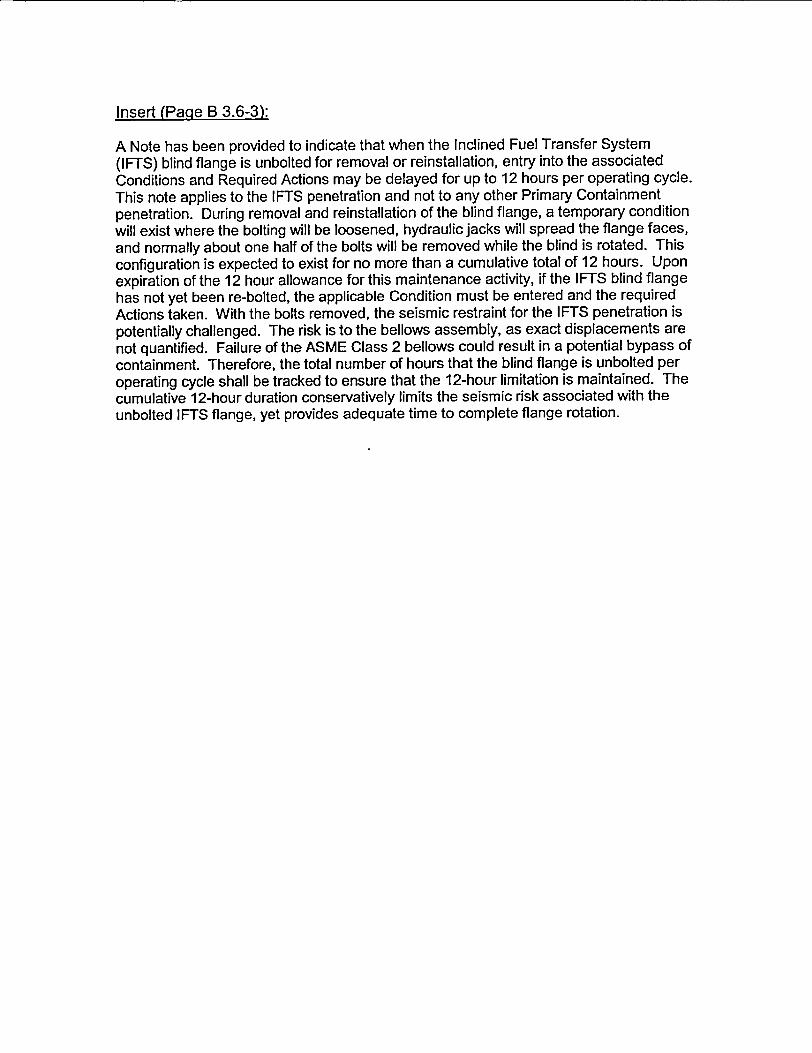
Insert (Page B 3.6-3):
A Note has been provided to indicate that when the Inclined Fuel Transfer System(IFTS) blind flange is unbolted for removal or reinstallation, entry into the associatedConditions and Required Actions may be delayed for up to 12 hours per operating cycle.This note applies to the IFTS penetration and not to any other Primary Containmentpenetration. During removal and reinstallation of the blind flange, a temporary conditionwill exist where the bolting will be loosened, hydraulic jacks will spread the flange faces,and normally about one half of the bolts will be removed while the blind is rotated. Thisconfiguration is expected to exist for no more than a cumulative total of 12 hours. Uponexpiration of the 12 hour allowance for this maintenance activity, if the IFTS blind flangehas not yet been re-bolted, the applicable Condition must be entered and the requiredActions taken. With the bolts removed, the seismic restraint for the IFTS penetration ispotentially challenged. The risk is to the bellows assembly, as exact displacements arenot quantified. Failure of the ASME Class 2 bellows could result in a potential bypass ofcontainment. Therefore, the total number of hours that the blind flange is unbolted peroperating cycle shall be tracked to ensure that the 12-hour limitation is maintained. Thecumulative 12-hour duration conservatively limits the seismic risk associated with theunbolted IFTS flange, yet provides adequate time to complete flange rotation.

ATTACHMENT 4
INFORMATION SUPPORTING A FINDING OFNO SIGNIFICANT HAZARDS CONSIDERATION
According to 10 CFR 50.92, "Issuance of amendment.", paragraph (c) a proposedamendment to an operating license involves no significant hazards consideration ifoperation of the facility in accordance with the proposed amendment would not:
(1) Involve a significant increase in the probability of occurrence orconsequences of an accident previously evaluated; or,
(2) Create the possibility of a new or different kind of accident from anypreviously analyzed; or,
(3) Involve a significant reduction in a margin of safety.
AmerGen Energy Company, LLC (i.e., AmerGen), proposes changes to Appendix A,Technical Specifications (TS), of Facility Operating License No. NPF-62. Specifically,we propose to add a conditional Note to the Actions associated with TS Section 3.6.1.3,"Primary Containment Isolation Valves (PCIVs)," which will provide the requiredconditions to be met when removing the Inclined Fuel Transfer System (IFTS) blindflange during Modes 1, 'Power Operation," 2, "Startup," or 3, "Hot Shutdown." Theproposed changes also delete conditional Note 3 to TS Section 3.6.1.3 SurveillanceRequirement (SR) 3.6.1.3.3 added in Amendment 107. In addition to the above, theproposed changes also include the addition of a conditional note to TS Section 3.6.1.1 toprovide a 12 hour delay during removal and reinstallation of the blind flange before theTS Actions are required to be entered when the IFTS blind flange is unbolted in Modes1, 2, or 3.
Information supporting the determination that the criteria set forth in 10 CFR 50.92 aremet for this amendment request is indicated below.
Does the change involve a significant increase in the probability or consequencesof an accident previously evaluated?
The proposed changes allow operation of the IFTS while primary containmentoperability is required. The proposed changes result in a change to the primarycontainment boundary. A loss of primary containment integrity is not an accidentinitiator. The proposed changes do not involve any modifications to plantsystems or design parameters or conditions that contribute to the initiation of anyaccidents previously evaluated. Therefore, the proposed changes do notincrease the probability of any accident previously evaluated.
The proposed changes potentially affect the allowable leakage of thecontainment structure which is designed to mitigate the consequences of a loss-of-coolant accident (LOCA). The function of the primary containment is tomaintain functional integrity during and following the peak transient pressuresand temperatures that result from any LOCA. The primary containment isdesigned to limit fission product leakage following the design basis LOCA.Because the proposed changes do not alter the plant design, only the extent of
Page 1 of 4
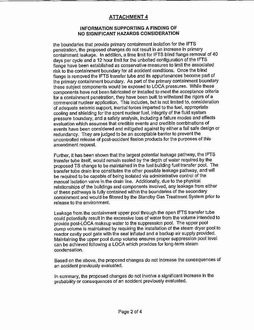
ATTACHMENT 4
INFORMATION SUPPORTING A FINDING OFNO SIGNIFICANT HAZARDS CONSIDERATION
the boundaries that provide primary containment isolation for the IFTSpenetration, the proposed changes do not result in an increase in primarycontainment leakage. In addition, a time limit for IFTS blind flange removal of 40days per cycle and a 12 hour limit for the unbolted configuration of the IFTSflange have been established as conservative measures to limit the associatedrisk to the containment boundary for all accident conditions. Once the blindflange is removed the IFTS transfer tube and its appurtenances become part ofthe primary containment boundary. As part of the primary containment boundarythese subject components would be exposed to LOCA pressures. While thesecomponents have not been fabricated or installed to meet the acceptance criteriafor a containment penetration, they have been built to withstand the rigors of acommercial nuclear application. This includes, but is not limited to, considerationof adequate seismic support, inertial forces imparted to the fuel, appropriatecooling and shielding for the spent nuclear fuel, integrity of the fluid systempressure boundary, and a safety analysis, including a failure modes and effectsevaluation which assumes that credible events and credible combinations ofevents have been considered and mitigated against by either a fail safe design orredundancy. They are judged to be an acceptable barrier to prevent theuncontrolled release of post-accident fission products for the purposes of thisamendment request.
Further, it has been shown that the largest potential leakage pathway, the IFTStransfer tube itself, would remain sealed by the depth of water required by theproposed TS change to be maintained in the fuel building fuel transfer pool. Thetransfer tube drain line constitutes the other possible leakage pathway, and willbe required to be capable of being isolated via administrative control of themanual isolation valve in the drain line. Additionally, due to the physicalrelationships of the buildings and components involved, any leakage from eitherof these pathways is fully contained within the boundaries of the secondarycontainment and would be filtered by the Standby Gas Treatment System prior torelease to the environment.
Leakage from the containment upper pool through the open IFTS transfer tubecould potentially result in the excessive loss of water from the volume intended toprovide post-LOCA makeup water to the suppression pool. The upper pooldump volume is maintained by requiring the installation of the steam dryer pool toreactor cavity pool gate with the seal inflated and a backup air supply provided.Maintaining the upper pool dump volume ensures proper suppression pool levelcan be achieved following a LOCA which provides for long-term steamcondensation.
Based on the above, the proposed changes do not increase the consequences ofan accident previously evaluated.
In summary, the proposed changes do not involve a significant increase in theprobability or consequences of an accident previously evaluated.
Page 2 of 4

ATTACHMENT 4
INFORMATION SUPPORTING A FINDING OFNO SIGNIFICANT HAZARDS CONSIDERATION
Does the change create the possibility of a new or different kind of accident fromany accident previously evaluated?
The proposed changes do not involve a change to the plant design or operationexcept for when IFTS is operated. As a result, the proposed changes do notaffect any of the parameters or conditions that could contribute to the initiation ofany accidents. No new accident modes or equipment failure modes are createdby these changes. Extending the primary containment boundary to includeportions of the IFTS has no influence on, nor does it contribute to the possibilityof a new or different kind of accident or malfunction from those previouslyevaluated. Furthermore, operation of IFTS is unrelated to the operation of thereactor. There is no mishap in the process that can lead or contribute to thepossibility of losing any coolant in the reactor or introducing the chance forpositive or negative reactivity or other accidents different from and not boundedby those previously evaluated. Therefore, these proposed changes do not createthe possibility of a new or different kind of accident from any accident previouslyevaluated.
Does the change involve a significant reduction in a margin of safety?
The proposed changes only affect the extent of a portion of the primarycontainment boundary. The time that the IFTS is in the seismically indeterminateconfiguration with the flange unbolted will be limited to 12 hours per operatingcycle. The time the IFTS blind flange will be removed will be limited to 40 daysper operating cycle. These restrictions will limit the risk from the potentialleakage through the primary containment boundary. Having IFTS in operationdoes not affect the reliability of equipment used for core cooling. In addition,precautions will be taken to administratively control the IFTS transfer tube drainpath so that the proposed change will not increase the probability that anincrease in leakage from the primary containment to the secondary containmentcould occur. Precautions will also be taken to ensure that the steam dryer poolto reactor cavity pool gate is installed prior to removing the IFTS flange whenprimary containment is required to be operable. Installation of this gate willensure that an adequate containment upper pool dump volume is maintained tosupport post-LOCA suppression pool makeup water volume requirements.
The margin of safety that has the potential of being impacted by the proposedchanges involve the offsite dose consequences of postulated accidents whichare directly related to containment leakage rate. The containment isolationsystem is designed to limit leakage to La which is defined by the CPS TS to be0.65% of primary containment air weight per day at the design basis LOCAmaximum peak containment pressure (i.e., Pa). The limitation on containmentleakage rate is designed to ensure that total leakage volume will not exceed thevolume assumed in the accident analyses at Pa. The margin of safety for theoffsite dose consequences of postulated accidents directly related to thecontainment leakage rate is maintained by meeting the La acceptance criteriaduring operation. The La value is not being modified by this proposed TSchange. The IFTS will continue to provide an acceptable barrier to prevent
Page 3 of 4

ATTACHMENT 4
INFORMATION SUPPORTING A FINDING OFNO SIGNIFICANT HAZARDS CONSIDERATION
unacceptable containment leakage during a LOCA, and therefore these changeswill not create a situation causing the containment leakage rate acceptancecriteria to be violated.
Therefore, the proposed changes do not involve a significant reduction in themargin of safety.
Based on the above evaluation, we have concluded that the proposed changes do notinvolve a significant hazards consideration.
Page 4 of 4