class 20-21-22 23 composites and pmc
DESCRIPTION
CompositesTRANSCRIPT
Components in a Composite Material
• Nearly all composite materials consist of two phases:
1. Primary phase - forms the matrix within which the secondary phase is imbedded
2. Secondary phase - imbedded phase, sometimes referred to as a reinforcing agent
• The reinforcing phase may be in the form of fibers, particles, or various other geometries
Adapted from “Fundamentals of Modern Manufacturing,” M. P. Groover, 2nd Ed., 2002, John Wiley & Sons, Inc.

Adapted from “Fundamentals of Modern Manufacturing,” M. P. Groover, 2nd Ed., 2002, John Wiley & Sons, Inc.

Figure 9.1 - Possible physical shapes of imbedded phases in composite materials: (a) fiber, (b) particle, and (c) flake
Fibers: usually circular in cross-section
• Diameters range from less than 0.0025 mm to about 0.13 mm, depending on material
• Filaments provide greatest opportunity for strength enhancement of composites
The filament form of most materials is significantly stronger than the bulk form
Size effect: as size/diameter is reduced, the material becomes oriented in the fiber axis direction and probability of defects in the structure decreases
Adapted from “Fundamentals of Modern Manufacturing,” M. P. Groover, 2nd Ed., 2002, John Wiley & Sons, Inc.

Adapted from “Fundamentals of Modern Manufacturing,” M. P. Groover, 2nd Ed., 2002, John Wiley & Sons, Inc.

Typical Properties of Common Fibers
Adapted from “Fundamentals of Modern Manufacturing,” M. P. Groover, 2nd Ed., 2002, John Wiley & Sons, Inc.
Continuous vs. Discontinuous Fibers
• Continuous fibers - very long; in theory, they offer a continuous path by which a load can be carried by the composite part
• Discontinuous fibers (chopped sections of continuous fibers) - short lengths (L/D = roughly 100)
– Important type of discontinuous fiber are whiskers - hair-like single crystals with diameters down to about 0.001 mm with very high strength
Adapted from “Fundamentals of Modern Manufacturing,” M. P. Groover, 2nd Ed., 2002, John Wiley & Sons, Inc.

Fiber Orientation • One-dimensional reinforcement: maximum strength
and stiffness are obtained in the direction of the fiber
• Planar reinforcement: in some cases in the form of a two-dimensional woven fabric
• Random or three-dimensional: composite material tends to possess isotropic properties
Figure 9.3 - Fiber orientation in composite materials: (a) one-dimensional, continuous fibers; (b) planar, continuous fibers in the form of a woven fabric;
(c) random, discontinuous fibers
Adapted from “Fundamentals of Modern Manufacturing,” M. P. Groover, 2nd Ed., 2002, John Wiley & Sons, Inc.

Materials for Fibers
• Fiber materials in fiber-reinforced composites: – Glass – most widely used filament
– Carbon – high elastic modulus
– Boron – very high elastic modulus
– Polymers - Kevlar
– Ceramics – SiC and Al2O3
– Metals - steel
• The most important commercial use of fibers is in PMCs
Adapted from “Fundamentals of Modern Manufacturing,” M. P. Groover, 2nd Ed., 2002, John Wiley & Sons, Inc.

Particles and Flakes
• A second common shape of imbedded phase is particulate, ranging in size from microscopic to macroscopic
• Flakes are basically two-dimensional particles - small flat platelets
• Distribution of particles in the matrix is random, and therefore strength and other properties of the composite material are usually isotropic
• Strengthening mechanism depends on particle size
Adapted from “Fundamentals of Modern Manufacturing,” M. P. Groover, 2nd Ed., 2002, John Wiley & Sons, Inc.

Interface • There is always an interface between constituent
phases in a composite material • For the composite to operate effectively, the phases
must bond where they join at the interface
Figure 9.4 - Interfaces between phases in a composite material:
(a) direct bonding between primary and secondary phases
Adapted from “Fundamentals of Modern Manufacturing,” M. P. Groover, 2nd Ed., 2002, John Wiley & Sons, Inc.

Interphase
• In some cases, a third ingredient must be added to achieve bonding of primary and secondary phases
• Called an interphase, this third ingredient can be thought of as an adhesive
Figure 9.4 - Interfaces between phases: (b) addition of a third
ingredient to bond the primary phases and form an interphase
Adapted from “Fundamentals of Modern Manufacturing,” M. P. Groover, 2nd Ed., 2002, John Wiley & Sons, Inc.
Other Types of Composite Structures
• Laminar composite structure – conventional
• Sandwich structure
• Honeycomb sandwich structure
Adapted from “Fundamentals of Modern Manufacturing,” M. P. Groover, 2nd Ed., 2002, John Wiley & Sons, Inc.

Laminar Two or more layers bonded together in an integral
piece • Example: plywood in which layers are the same
wood, but grains are oriented differently to increase overall strength of the laminated piece
Figure 9.7 - Laminar composite
structures: (a) conventional laminar
structure
Adapted from “Fundamentals of Modern Manufacturing,” M. P. Groover, 2nd Ed., 2002, John Wiley & Sons, Inc.

Sandwich Structure – Foam Core Consists of a relatively thick core of low density
foam bonded on both faces to thin sheets of a different material
Figure 9.7 - Laminar
composite structures: (b)
sandwich structure using foam
core
Adapted from “Fundamentals of Modern Manufacturing,” M. P. Groover, 2nd Ed., 2002, John Wiley & Sons, Inc.
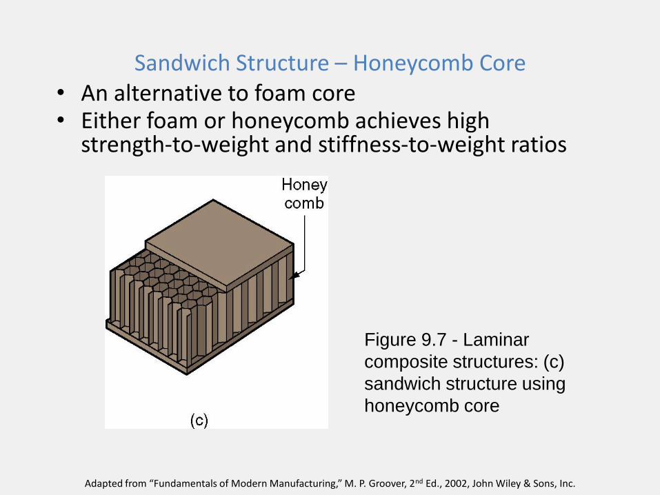
Sandwich Structure – Honeycomb Core • An alternative to foam core • Either foam or honeycomb achieves high
strength-to-weight and stiffness-to-weight ratios
Figure 9.7 - Laminar
composite structures: (c)
sandwich structure using
honeycomb core
Adapted from “Fundamentals of Modern Manufacturing,” M. P. Groover, 2nd Ed., 2002, John Wiley & Sons, Inc.

Figure 9.11 - Composite materials in the Boeing 757
(courtesy of Boeing Commercial Airplane Group)
Adapted from “Fundamentals of Modern Manufacturing,” M. P. Groover, 2nd Ed., 2002, John Wiley & Sons, Inc.

SHAPING PROCESSES FOR POLYMER MATRIX COMPOSITES
https://www.youtube.com/watch?v=Gd1dkrX8JFU&index=7&list=PL3B2C07E01F72869B
• Starting Materials for PMCs
• Open Mold Processes
• Closed Mold Processes
• Filament Winding
• Pultrusion Processes
• Other PMC Shaping Processes
Adapted from “Fundamentals of Modern Manufacturing,” M. P. Groover, 2nd Ed., 2002, John Wiley & Sons, Inc.

Adapted from “Fundamentals of Modern Manufacturing,” M. P. Groover, 2nd Ed., 2002, John Wiley & Sons, Inc.

Adapted from “Fundamentals of Modern Manufacturing,” M. P. Groover, 2nd Ed., 2002, John Wiley & Sons, Inc.

Adapted from “Fundamentals of Modern Manufacturing,” M. P. Groover, 2nd Ed., 2002, John Wiley & Sons, Inc.

Adapted from “Fundamentals of Modern Manufacturing,” M. P. Groover, 2nd Ed., 2002, John Wiley & Sons, Inc.

Polymer Matrix Composites (PMCs)
A polymer primary phase in which a secondary phase is imbedded as fibers, particles, or flakes
• Commercially, PMCs are more important than MMCs or CMCs
• Examples: most plastic molding compounds, rubber reinforced with carbon black, and fiber-reinforced polymers (FRPs)
• FRPs are most closely identified with the term composite
Adapted from “Fundamentals of Modern Manufacturing,” M. P. Groover, 2nd Ed., 2002, John Wiley & Sons, Inc.

FRP Applications
• Aerospace – much of the structural weight of today’s airplanes and helicopters consist of advanced FRPs
• Automotive – some body panels for cars and trucks
• Sports and recreation – Fiberglass reinforced plastic has been used for
boat hulls since the 1940s – Fishing rods, tennis rackets, golf club shafts,
helmets, skis, bows and arrows.
Adapted from “Fundamentals of Modern Manufacturing,” M. P. Groover, 2nd Ed., 2002, John Wiley & Sons, Inc.

Other Polymer Matrix Composites
• In addition to FRPs, other PMCs contain particles, flakes, and short fibers as the secondary phase
• Called fillers when used in molding compounds
• Two categories: 1. Reinforcing fillers – used to strengthen or
otherwise improve mechanical properties • Examples: wood flour in phenolic and amino resins;
and carbon black in rubber
2. Extenders – used to increase bulk and reduce cost per unit weight, but little or no effect on mechanical properties
Adapted from “Fundamentals of Modern Manufacturing,” M. P. Groover, 2nd Ed., 2002, John Wiley & Sons, Inc.

Challenges for PMC Shape Processing
• Some of the PMC shaping processes are slow and labor intensive
• In general, techniques for shaping composites are less efficient than for other materials: – Composite materials are more complex than other
materials
– For FRPs, there is the need to orient the reinforcing phase
– Relatively new category of materials; less development of manufacturing processes
Adapted from “Fundamentals of Modern Manufacturing,” M. P. Groover, 2nd Ed., 2002, John Wiley & Sons, Inc.

Categories of FRP Shape Processes
• Open mold processes - some of the original manual procedures for laying resins and fibers onto forms
• Closed mold processes - much the same as those used in plastic molding
• Filament winding - continuous filaments are dipped in liquid resin and wrapped around a rotating mandrel, producing a rigid, hollow, cylindrical shape
• Pultrusion - similar to extrusion only adapted to include continuous fiber reinforcement
• Other
Adapted from “Fundamentals of Modern Manufacturing,” M. P. Groover, 2nd Ed., 2002, John Wiley & Sons, Inc.

Figure 15.1 -
Classification of manufacturing processes for fiber reinforced polymer (FRP) composites
Adapted from “Fundamentals of Modern Manufacturing,” M. P. Groover, 2nd Ed., 2002, John Wiley & Sons, Inc.

Starting Materials for PMCs
• In a PMC, the starting materials are:
– A polymer
– A reinforcing phase
• These are processed separately before becoming phases in the composite
Adapted from “Fundamentals of Modern Manufacturing,” M. P. Groover, 2nd Ed., 2002, John Wiley & Sons, Inc.

Polymer Matrix
• Thermosetting (TS) polymers are the most common matrix materials - the principal TS polymers are: – Phenolics – used with particulate reinforcing phases
– Polyesters and epoxies - more closely associated with FRPs
• Thermoplastic molding compounds are composite materials that include fillers or reinforcing agents
• Most commercial elastomers are composite materials since nearly all rubbers are reinforced with carbon black
Adapted from “Fundamentals of Modern Manufacturing,” M. P. Groover, 2nd Ed., 2002, John Wiley & Sons, Inc.

Reinforcing Agent
• Possible geometries - fibers, particles, and flakes
• Possible materials - ceramics, metals, other polymers, or elements such as carbon or boron
• Particles and flakes are used in many plastic molding compounds
• Of most engineering interest is the use of fibers as the reinforcing phase
Adapted from “Fundamentals of Modern Manufacturing,” M. P. Groover, 2nd Ed., 2002, John Wiley & Sons, Inc.

Fibers as the Reinforcing Phase in FRPs
• Common fiber materials: glass, carbon, and Kevlar (a polymer)
• In some fabrication processes, the filaments are continuous, while in others, they are chopped into short lengths – In continuous form, individual filaments are usually
available as rovings - collections of untwisted continuous strands, convenient for handling
– By contrast, a yarn is a twisted collection of filaments
Adapted from “Fundamentals of Modern Manufacturing,” M. P. Groover, 2nd Ed., 2002, John Wiley & Sons, Inc.

Fibers as the Reinforcing Phase – Contd.
• The most familiar form of continuous fiber is a cloth - a fabric of woven yarns
• Similar to a cloth is a woven roving, a fabric consisting of untwisted filaments rather than yarns – Can be produced with unequal numbers of strands
in the two directions for greater strength in one direction
– Such unidirectional woven rovings are often preferred in laminated FRP composites
Woven carbon fiber cloth. Source: Wikipedia
Adapted from “Fundamentals of Modern Manufacturing,” M. P. Groover, 2nd Ed., 2002, John Wiley & Sons, Inc.

Mats and Preforms as the Reinforcing Phase
• Fibers can also be in a mat form - a felt consisting of randomly oriented short fibers held loosely together with a binder, sometimes in a carrier fabric – Mats are commercially available as blankets of various
weights, thicknesses, and widths – Mats can be cut and shaped for use as preforms in
some of the closed mold processes
• During molding, the resin impregnates the preform and then cures, thus yielding a fiber-reinforced molding
Adapted from “Fundamentals of Modern Manufacturing,” M. P. Groover, 2nd Ed., 2002, John Wiley & Sons, Inc.

Alternatives for Combining Matrix and Reinforcement in PMCs
1. The starting materials arrive at the fabrication operation as separate entities and are combined into the composite during shaping – Examples: filament winding and pultrusion, in which
reinforcing phase is continuous fibers
2. The two component materials are combined into some starting form that is convenient for use in the shaping process – Molding compounds
– Prepregs
Adapted from “Fundamentals of Modern Manufacturing,” M. P. Groover, 2nd Ed., 2002, John Wiley & Sons, Inc.

Molding Compounds FRP composite molding compounds consist of the
resin matrix with short randomly dispersed fibers • Similar to those used in plastic molding. Most
molding compounds for composite processing are thermosetting polymers
• Since they are designed for molding operations, they must be capable of flowing – i.e., they have not been cured prior to shape processing
• Curing is done during and/or after final shaping
Adapted from “Fundamentals of Modern Manufacturing,” M. P. Groover, 2nd Ed., 2002, John Wiley & Sons, Inc.

Prepregs
Fibers impregnated with partially cured TS resins to facilitate shape processing
• Available as tapes or cross-plied sheets or fabrics
• Curing is completed during and/or after shaping
• Advantage: prepregs are fabricated with continuous filaments rather than chopped random fibers, thus increasing strength and modulus
Adapted from “Fundamentals of Modern Manufacturing,” M. P. Groover, 2nd Ed., 2002, John Wiley & Sons, Inc.

Open Mold Processes
Family of FRP shaping processes that use a single positive or negative mold surface to produce laminated FRP structures
• The starting materials (resins, fibers, mats, and woven rovings) are applied to the mold in layers, building up to the desired thickness
• This is followed by curing and part removal
• Common resins are unsaturated polyesters and epoxies, using fiberglass as the reinforcement
Adapted from “Fundamentals of Modern Manufacturing,” M. P. Groover, 2nd Ed., 2002, John Wiley & Sons, Inc.

Open Mold FRP Processes
1. Hand lay-up
2. Spray-up
3. Automated tape-laying machines
• The differences are in the methods of applying the laminations to the mold, alternative curing techniques, and other differences
Adapted from “Fundamentals of Modern Manufacturing,” M. P. Groover, 2nd Ed., 2002, John Wiley & Sons, Inc.
Hand Lay-Up Method
Open mold shaping method in which successive layers of resin and reinforcement are manually applied to an open mold to build the laminated FRP composite structure
• Labor-intensive
• Finished molding must usually be trimmed with a power saw to size outside edges
• Oldest open mold method for FRP laminates, dating to the 1940s when it was first used for boat hulls
Adapted from “Fundamentals of Modern Manufacturing,” M. P. Groover, 2nd Ed., 2002, John Wiley & Sons, Inc.

Figure 15.4 - Hand lay-up : (1) mold is treated with mold release agent; (2) thin gel coat (resin, colored) is applied, to be the outside surface of molding; (3) when gel coat has partially set, layers of resin and fiber are applied, the fiber is in the form of mat or cloth; each layer is rolled to impregnate the fiber with resin and remove air; (4) part is cured; (5) fully hardened part is removed from mold
Adapted from “Fundamentals of Modern Manufacturing,” M. P. Groover, 2nd Ed., 2002, John Wiley & Sons, Inc.

Products Made by Hand Lay-Up
• Generally large in size but low in production quantity - not economical for high production
• In addition to boat hulls, other applications include: swimming pools, large container tanks, stage props, etc.
• The largest moldings ever made were ship hulls for the British Royal Navy: 85 m (280 ft) long
Adapted from “Fundamentals of Modern Manufacturing,” M. P. Groover, 2nd Ed., 2002, John Wiley & Sons, Inc.

Spray-Up Method
Liquid resin and chopped fibers are sprayed onto an open mold to build successive FRP laminations
• It is an attempt to mechanize application of resin-fiber layers and reduce lay-up time
• It is an alternative for step (3) in the hand lay-up procedure
Adapted from “Fundamentals of Modern Manufacturing,” M. P. Groover, 2nd Ed., 2002, John Wiley & Sons, Inc.

Figure 15.5 - Spray-up method
Adapted from “Fundamentals of Modern Manufacturing,” M. P. Groover, 2nd Ed., 2002, John Wiley & Sons, Inc.

Products Made by Spray-Up
• Boat hulls, bathtubs, shower stalls, automobile and truck body parts, recreational vehicle components, furniture, large structural panels, and containers
• Movie and stage props are sometimes made by this method
• Since products made by spray-up have randomly oriented short fibers, they are not as strong as those made by lay-up, in which the fibers are continuous and directed
Adapted from “Fundamentals of Modern Manufacturing,” M. P. Groover, 2nd Ed., 2002, John Wiley & Sons, Inc.

Automated Tape-Laying Machines
Automated tape-laying machines operate by dispensing a prepreg tape onto an open mold following a programmed path
• The typical machine consists of an overhead gantry to which the dispensing head is attached
• The gantry permits x-y-z travel of the head, for positioning and following a defined continuous path
Adapted from “Fundamentals of Modern Manufacturing,” M. P. Groover, 2nd Ed., 2002, John Wiley & Sons, Inc.

Figure 15.6 - Automated tape-laying machine
(courtesy Cincinnati Milacron) Adapted from “Fundamentals of Modern Manufacturing,” M. P. Groover, 2nd Ed., 2002, John Wiley & Sons, Inc.

Curing in Open Mold Processes
• Curing is required of all thermosetting resins used in FRP laminated composites
• Curing cross-links the polymer, transforming it from its liquid or highly plastic condition into a hardened product
• Three principal process parameters in curing: 1. Time
2. Temperature
3. Pressure
Adapted from “Fundamentals of Modern Manufacturing,” M. P. Groover, 2nd Ed., 2002, John Wiley & Sons, Inc.

Curing at Room Temperature
• Curing normally occurs at room temperature for the TS resins used in hand lay-up and spray-up procedures
– Moldings made by these processes are often large (e.g., boat hulls), and heating would be difficult
– In some cases, days are required before room temperature curing is sufficiently complete to remove the part
Adapted from “Fundamentals of Modern Manufacturing,” M. P. Groover, 2nd Ed., 2002, John Wiley & Sons, Inc.

Curing Methods that Use Heating
• Oven curing provides heat at closely controlled temperatures; some curing ovens are equipped to draw a partial vacuum
• Infrared heating can be used in applications where it is impractical to place the molding in an oven
• Curing in an autoclave provides control over both temperature and pressure – Autoclave - an enclosed chamber equipped to apply
heat and/or pressure at controlled levels – In FRP composites processing, it is usually a large
horizontal cylinder with doors at either end
Adapted from “Fundamentals of Modern Manufacturing,” M. P. Groover, 2nd Ed., 2002, John Wiley & Sons, Inc.

Closed Mold Processes
• Performed in molds consisting of two sections that open and close each molding cycle
• Tooling cost is more than twice the cost of a comparable open mold due to the more complex equipment required in these processes
• Advantages of a closed mold are: (1) good finish on all part surfaces, (2) higher production rates, (3) closer control over tolerances, and (4) more complex three-dimensional shapes are possible
Adapted from “Fundamentals of Modern Manufacturing,” M. P. Groover, 2nd Ed., 2002, John Wiley & Sons, Inc.

Classification of Closed Mold Processes
• Three classes based on their counterparts in conventional plastic molding:
1. Compression molding
2. Transfer molding
3. Injection molding
• The terminology is often different when polymer matrix composites are molded
Adapted from “Fundamentals of Modern Manufacturing,” M. P. Groover, 2nd Ed., 2002, John Wiley & Sons, Inc.

Compression Molding PMC Processes
A charge is placed in the lower mold section, and the sections are brought together under pressure, causing the charge to take the shape of the cavity
• The mold halves are heated to cure the TS polymer
• When the molding is sufficiently cured, the mold is opened and the part is removed
• There are several shaping processes for PMCs based on compression molding; the differences are mostly in the form of the starting materials
Adapted from “Fundamentals of Modern Manufacturing,” M. P. Groover, 2nd Ed., 2002, John Wiley & Sons, Inc.

Transfer Molding PMC Processes
A charge of thermosetting resin with short fibers is placed in a pot or chamber, heated, and squeezed by ram action into one or more mold cavities
• The mold is heated to cure the resin
• The name of the process derives from the fact that the fluid polymer is transferred from a pot into a mold
Adapted from “Fundamentals of Modern Manufacturing,” M. P. Groover, 2nd Ed., 2002, John Wiley & Sons, Inc.

Injection Molding PMC Processes
• Injection molding is noted for low cost production of plastic parts in large quantities
• Although most closely associated with thermoplastics, the process can also be adapted to thermosets
• Processes of interest in the context of PMCs:
– Conventional injection molding
– Reinforced reaction injection molding
Adapted from “Fundamentals of Modern Manufacturing,” M. P. Groover, 2nd Ed., 2002, John Wiley & Sons, Inc.

Conventional Injection Molding
• Used for both TP and TS type FRPs
• Virtually all TP polymers can be reinforced with fibers
• Chopped fibers must be used; if continuous, the fibers would be reduced by the action of the rotating screw in the barrel anyway
• During injection into the mold cavity, the fibers tend to become aligned as they pass the nozzle – Designers can sometimes exploit this feature to
optimize directional properties in the part
Adapted from “Fundamentals of Modern Manufacturing,” M. P. Groover, 2nd Ed., 2002, John Wiley & Sons, Inc.

Reinforced Reaction Injection Molding
Reaction injection molding (RIM) - two reactive ingredients are mixed and injected into a mold cavity where curing and solidification occur due to chemical reaction rather than heat
Adapted from “Fundamentals of Modern Manufacturing,” M. P. Groover, 2nd Ed., 2002, John Wiley & Sons, Inc.
Reinforced Reaction Injection Molding - 2
Reinforced reaction injection molding (RRIM) is a closely related process that includes reinforcing fibers, typically glass, in the mixture
• Advantages: similar to RIM (e.g., no heat energy required, lower cost mold), with the added benefit of fiber-reinforcement
• Products: auto body and truck cab applications for bumpers, fenders, and other body parts
Adapted from “Fundamentals of Modern Manufacturing,” M. P. Groover, 2nd Ed., 2002, John Wiley & Sons, Inc.

Filament Winding
Resin-impregnated continuous fibers are wrapped around a rotating mandrel that has the internal shape of the desired FRP product; the resin is then cured and the mandrel removed
• The fiber rovings are pulled through a resin bath immediately before being wound in a helical pattern onto the mandrel
• The operation is repeated to form additional layers, each having a criss-cross pattern with the previous, until the desired part thickness has been obtained
Adapted from “Fundamentals of Modern Manufacturing,” M. P. Groover, 2nd Ed., 2002, John Wiley & Sons, Inc.

Figure 15.8 - Filament winding
Adapted from “Fundamentals of Modern Manufacturing,” M. P. Groover, 2nd Ed., 2002, John Wiley & Sons, Inc.


Adapted from “Fundamentals of Modern Manufacturing,” M. P. Groover,
2nd Ed., 2002, John Wiley & Sons, Inc.

Figure 15.10 - Filament winding machine
(courtesy Cincinnati Milacron)
Adapted from “Fundamentals of Modern Manufacturing,” M. P. Groover, 2nd Ed., 2002, John Wiley & Sons, Inc.


https://www.youtube.com/watch?v
=Gd1dkrX8JFU&index=7&list=PL
3B2C07E01F72869B

Pultrusion Processes
Similar to extrusion (hence the name similarity) but workpiece is pulled through die (so prefix "pul-" in place of "ex-")
• Like extrusion, pultrusion produces continuous straight sections of constant cross-section
• Developed around 1950 for making fishing rods of glass fiber reinforced polymer (GFRP)
Adapted from “Fundamentals of Modern Manufacturing,” M. P. Groover, 2nd Ed., 2002, John Wiley & Sons, Inc.

Pultrusion
Continuous fiber rovings are dipped into a resin bath and pulled through a shaping die where the impregnated resin cures
• The sections produced are reinforced throughout their length by continuous fibers
• Like extrusion, the pieces have a constant cross-section, whose profile is determined by the shape of the die opening
• The cured product is cut into long straight sections
Adapted from “Fundamentals of Modern Manufacturing,” M. P. Groover, 2nd Ed., 2002, John Wiley & Sons, Inc.

Figure 15.11 - Pultrusion process
Adapted from “Fundamentals of Modern Manufacturing,” M. P. Groover, 2nd Ed., 2002, John Wiley & Sons, Inc.


Materials and Products in Pultrusion • Common resins: unsaturated polyesters, epoxies,
and silicones, all thermosetting polymers
• Difficulty with epoxies due to sticking on the die surface
• Reinforcing phase: E-glass is most widely, in proportions from 30% to 70%
• E and TS increase with reinforcement content
• Products: solid rods, tubing, long flat sheets, structural sections (such as channels, angled and flanged beams), tool handles for high voltage work, and third rail covers for subways.
Adapted from “Fundamentals of Modern Manufacturing,” M. P. Groover, 2nd Ed., 2002, John Wiley & Sons, Inc.

Pulforming • Pultrusion with additional steps to form the
length into a semicircular contour and alter the cross-section at one or more locations along the length
• Pultrusion is limited to straight sections of constant cross-section
• There is also a need for long parts with continuous fiber reinforcement that are curved rather than straight and whose cross-sections may vary throughout length – Pulforming is suited to these less regular shapes

Figure 15.12 - Pulforming process
(not shown in the sketch is the cut-off of the pulformed part)
Adapted from “Fundamentals of Modern Manufacturing,” M. P. Groover, 2nd Ed., 2002, John Wiley & Sons, Inc.

After exiting the shaping die, the continuous workpiece is
fed into a rotating table with negative molds positioned
around its periphery. The work is forced into the mold
cavities by a die shoe,which squeezes the cross section at
various locations and forms the curvature in the
length. The diameter of the table determines the radius of
the part. As the work leaves the die table, it is cut to length
to provide discrete parts. Resins and fibers similar to those
for pultrusion are used in pulforming. An important
application of the process is production of
automobile leaf springs.

Other PMC Shaping Processes • Centrifugal casting • Tube rolling • Continuous laminating • Cutting of FRPs • In addition, many of the traditional thermoplastic
shaping processes are applicable to FRPs (with short fibers) based on TP polymers; these include – Blow molding, Thermoforming, Extrusion
Adapted from “Fundamentals of Modern Manufacturing,” M. P. Groover, 2nd Ed., 2002, John Wiley & Sons, Inc.

Centrifugal casting •This process is ideal for cylindrical products such as pipes
and tanks.
•The process is the same as its counterpart in metal casting
(Section 11.3.5).
•Chopped fibers combined with liquid resin are poured into a
fast-rotating cylindrical mold.
•Centrifugal force presses the ingredients against the mold
wall, where curing takes place.
•The resulting inner surfaces are quite smooth. Part shrinkage
or use of split molds permits part removal.

Tube rolling FRP tubes can be fabricated from prepreg sheets by a rolling technique,
shown in Figure 15.13. Such tubes are used in bicycle frames and space
trusses. In the process, a precut prepreg sheet is wrapped around a
cylindrical mandrel several times to obtain a tube wall of multiple sheet
thicknesses. The rolled sheets are then encased in a heat-shrinking
sleeve and oven cured. As the sleeve contracts, entrapped gases are
squeezed out the ends of the tube. When curing is complete, the mandrel
is removed to yield a rolled FRP tube. The operation is simple, and
tooling cost is low. There are variations in the process, such as using
different wrapping methods or using a steel mold to enclose the rolled
prepreg tube for better dimensional control.

Adapted from “Fundamentals of Modern Manufacturing,” M. P. Groover,
2nd Ed., 2002, John Wiley & Sons, Inc.
Continuous laminating Fiber-reinforced plastic panels, sometimes translucent and/or
corrugated, are used in construction. The process to produce them
consists of
(1) impregnating layers of glass fiber mat or woven fabric by dipping in
liquid resin or by passing beneath a doctor blade;
(2) gathering between cover films (cellophane, polyester, or other
polymer); and
(3) compacting between squeeze rolls and curing.
Corrugation (4) is added by formed rollers or mold shoes.

Cutting Methods
• Cutting of FRP laminated composites is required in both uncured and cured states
• Uncured materials (prepregs, preforms, SMCs, and other starting forms): – Must be cut to size for lay-up, molding, etc.
– Typical cutting tools: knives, scissors, power shears, and steel-rule blanking dies
– Nontraditional methods are also used, such as laser beam cutting and water jet cutting
Adapted from “Fundamentals of Modern Manufacturing,” M. P. Groover, 2nd Ed., 2002, John Wiley & Sons, Inc.

Cutting Methods - continued
• Cured FRPs are hard, tough, abrasive, and difficult-to-cut
– Cutting is required in many FRP products to trim excess material, cut holes and outlines, and so on
– For glass FRPs, cemented carbide cutting tools and high speed steel saw blades can be used - for some advanced composites (e.g., boron-epoxy), diamond cutting tools cut best
– Water jet cutting is also used, to reduce dust and noise problems with conventional sawing methods
Adapted from “Fundamentals of Modern Manufacturing,” M. P. Groover, 2nd Ed., 2002, John Wiley & Sons, Inc.