civil aviation guidance material – 6 805 aircraft mass …
TRANSCRIPT

CIVIL AVIATION AUTHORITY OF MALAYSIA
AIRCRAFT MASSCIVIL AVIATION GUIDANCE MATERIAL – 6805
ISSUE 01 REVISION 00 – 15TH SEPTEMBER 2021
AND BALANCE
AMBP
PROGRAMME

INTENTIONALLY LEFT BLANK

Introduction
Issue 01/Rev 00 CAGM 6805 – AMBP 3
Introduction This Civil Aviation Guidance Material 6805 (CAGM - 6805) is issued by the Civil Aviation Authority of Malaysia (CAAM) to provide guidance for mass and balance control of Malaysian registered aircraft, pursuant to Civil Aviation Directives 6805 – Aircraft Mass and Balance Programme.
Organisations may use these guidelines to demonstrate compliance with the provisions of the relevant CAD’s issued. Notwithstanding Regulation 204 and Regulation 205 of the Malaysian Civil Aviation Regulations 2016 (MCAR 2016), when the CAGMs issued by the CAAM are used, the related requirements of the CAD’s are considered as met, and further demonstration may not be required.
(Captain Chester Voo Chee Soon) Chief Executive Officer
Civil Aviation Authority of Malaysia

Introduction
Issue 01/Rev 00 CAGM 6805 – AMBP 4
Civil Aviation Guidance Material Components and Editorial practices This Civil Aviation Guidance Material is made up of the following components and are defined as follows: Standards: Usually preceded by words such as “shall” or “must”, are any specification for physical characteristics, configuration, performance, personnel or procedure, where uniform application is necessary for the safety or regularity of air navigation and to which Operators must conform. In the event of impossibility of compliance, notification to the CAAM is compulsory. Recommended Practices: Usually preceded by the words such as “should” or “may”, are any specification for physical characteristics, configuration, performance, personnel or procedure, where the uniform application is desirable in the interest of safety, regularity or efficiency of air navigation, and to which Operators will endeavour to conform. Appendices: Material grouped separately for convenience but forms part of the Standards and Recommended Practices stipulated by the CAAM. Definitions: Terms used in the Standards and Recommended Practices which are not self-explanatory in that they do not have accepted dictionary meanings. A definition does not have an independent status but is an essential part of each Standard and Recommended Practice in which the term is used, since a change in the meaning of the term would affect the specification. Tables and Figures: These add to or illustrate a Standard or Recommended Practice and which are referred to therein, form part of the associated Standard or Recommended Practice and have the same status. Notes: Included in the text, where appropriate, Notes give factual information or references bearing on the Standards or Recommended Practices in question but not constituting part of the Standards or Recommended Practices; Attachments: Material supplementary to the Standards and Recommended Practices or included as a guide to their application. It is to be noted that some Standards in this Civil Aviation Guidance Material incorporates, by reference, other specifications having the status of Recommended Practices. In such cases, the text of the Recommended Practice becomes part of the Standard.
The units of measurement used in this document are in accordance with the International System of Units (SI) as specified in CAD 5. Where CAD 5 permits the use of non-SI alternative units, these are shown in parentheses following the basic units. Where two sets of units are quoted it must not be assumed that the pairs of values are equal and interchangeable. It may, however, be inferred that an equivalent level of safety is achieved when either set of units is used exclusively. Any reference to a portion of this document, which is identified by a number and/or title, includes all subdivisions of that portion. Throughout this Civil Aviation Guidance Material, the use of the male gender should be understood to include male and female persons.

Record of Revisions
Issue 01/Rev 00 CAGM 6805 – AMBP 5
Record of Revisions Revisions to this CAGM shall be made by authorised personnel only. After inserting the revision, enter the required data in the revision sheet below. The ‘Initials’ has to be signed off by the personnel responsible for the change.
Rev No. Revision Date Revision Details Initials

Record of Revisions
Issue 01/Rev 00 CAGM 6805 – AMBP 6
INTENTIONALLY LEFT BLANK

Table of Contents
Issue 01/Rev 00 CAGM 6805 – AMBP 7
Table of Contents 1 GENERAL ........................................................................................................................... 1-1
1.1 PURPOSE ................................................................................................................................. 1-1 1.2 ABBREVIATIONS........................................................................................................................ 1-1
2 GENERAL REQUIREMENTS (CAD 6805 3) ............................................................................. 2-1 2.1 CAD 6805 3.4 – AIRCRAFT REWEIGHING .................................................................................... 2-1
3 AIRCRAFT WEIGHING (CAD 6805 4) .................................................................................... 3-1 3.1 CAD 6805 4.5 – CONDITION OF THE AIRCRAFT ......................................................................... 3-1 3.2 CAD 6805 4.6 – CALIBRATION OF WEIGHING EQUIPMENT.......................................................... 3-1 3.3 CAD 6805 4.8 – CONSISTENT WEIGHING MEASUREMENT .............................................................. 3-2
4 MASS AND BALANCE REPORT (MBR) (CAD 6805 5) .............................................................. 4-1 4.1 CAD 6805 5.1 – FORMAT AND CONTENT .................................................................................... 4-1 4.2 CAD 6805 5.3 – MBR SIGNATORY ............................................................................................ 4-1 4.3 CAD 6805 5.4 – MBR CONTRACT ............................................................................................. 4-2 4.4 CAD 6805 5.5 – CAAM APPROVAL OF MBR .............................................................................. 4-2
5 MASS AND CENTRE OF GRAVITY SCHEDULE (MCGS) (CAD 6805 6) ....................................... 5-1 5.1 CAD 6805 6.1 – FORMAT AND CONTENT .................................................................................... 5-1 5.2 CAD 6805 6.5 – MCGS SIGNATORY .......................................................................................... 5-3 5.3 CAD 6805 6.6 – MCGS CONTRACT ........................................................................................... 5-3 5.4 CAD 6805 6.7 – CAAM APPROVAL OF MCGS ............................................................................ 5-3
6 LOADING SCHEDULE (CAD 6805 7) ...................................................................................... 6-1 6.1 CAD 6805 7.1 – OPERATIONAL LIMIT ......................................................................................... 6-1 6.2 CAD 6805 7.3 – LOADING SCHEDULE ......................................................................................... 6-1 6.3 CAD 6805 7.5(C) – ACCEPTABLE ORGANISATION TO PRODUCE LOADING SCHEDULE ........................... 6-6 6.4 CAD 6805 7.6(A) – LOADING SCHEDULE CERTIFYING PERSONNEL QUALIFICATION .............................. 6-7
7 ON-BOARD MASS AND BALANCE SYSTEM (CAD 6805 9) ...................................................... 7-1 7.1 CAD 6805 9.2(B) – ON-BOARD MASS AND BALANCE SYSTEM ........................................................ 7-1
8 DRY OPERATING MASS (CAD 6805 10) ................................................................................ 8-1 8.1 CAD 6805 10.1 – DRY OPERATING MASS ................................................................................... 8-1
9 MASS OF PASSENGERS (CAD 6805 11) ................................................................................ 9-1 9.1 CAD 6805 11.1 – MASS VALUES FOR PASSENGERS ....................................................................... 9-1 9.2 CAD 6805 11.1 – PROCEDURES FOR ESTABLISHING REVISED STANDARD MASS VALUES FOR PASSENGERS 9-2
10 MASS OF FUEL (CAD 6805 13) ........................................................................................... 10-1 10.1 CAD 6805 13.1 – FUEL DENSITY .............................................................................................. 10-1
11 OPERATOR’S AIRCRAFT MASS AND BALANCE PROGRAMME (MBP) APPROVAL (CAD 6805 15) 11-1
11.1 CAD 6805 15.4 – MBP APPROVAL .......................................................................................... 11-1
12 APPENDICES .................................................................................................................... 12-1 12.1 APPENDIX 1 – MASS AND BALANCE REPORT (MBR) .............................................................. 12-1 12.2 APPENDIX 2 - MASS AND CENTRE OF GRAVITY SCHEDULE (MCGS) ...................................... 12-5 12.3 APPENDIX 3 - ADJUSTMENT OF STANDARD MASSES ............................................................ 12-9 12.4 APPENDIX 4 - STATISTICAL EVALUATION OF PASSENGERS DATA ........................................ 12-11

Table of Contents
Issue 01/Rev 00 CAGM 6805 – AMBP 8
12.5 APPENDIX 5 - GUIDANCE ON PASSENGER WEIGHING SURVEYS ......................................... 12-17

Chapter 1 – General
Issue 01/Rev 00 CAGM 6805 – AMBP 1-1
1 General
1.1 Purpose
1.1.1 CAD 6, Part I, Chapter 5 and Part III, Section 2, Chapter 3 require that aeroplanes and helicopters be operated in accordance with a comprehensive and detailed code of performance in compliance with the applicable standards including mass limitations and centre of gravity limitations as specified in the aircraft flight manual. To satisfy this requirement, operators are required to develop and maintain a mass and balance programme.
1.1.2 The primary purpose of aircraft mass and balance control is safety. A secondary purpose is to achieve the utmost in efficiency during operation of the aircraft. Improper loading reduces the efficiency of operating an aircraft and can be the cause of a failure to start or complete a flight.
1.2 Abbreviations
AFM = Aircraft Flight Manual
AMO = Approved maintenance Organisation
BA = Balance Arms
CAME = Continuing Airworthiness Management Exposition
CAMO = Continuing Airworthiness Management Organisation
CG = Centre of Gravity
MAC = Mean Aerodynamic Chord
MBP = Mass and Balance Programme
MBR = Mass and Balance Report
MCGS = Mass and Centre of Gravity Schedule
SOC = Statement of Compliance
TC = Type Certificate
ULD = Unit Load Device

Chapter 1 – General
Issue 01/Rev 00 CAGM 6805 – AMBP 1-2
INTENTIONALLY LEFT BLANK

Chapter 2 – General Requirements
Issue 01/Rev 00 CAGM 6805 – AMBP 2-1
2 General Requirements (CAD 6805 3)
2.1 CAD 6805 3.4 – Aircraft Reweighing
2.1.1 Reweighing of the aircraft is dependent on several factors: the date of last weighing, history of the aircraft or embodiment of modifications and repairs. Consultation with CAAM is recommended if clarification is needed on reweighing based on the history of the aircraft or incorporation of modifications and repairs.

Chapter 2 – General Requirements
Issue 01/Rev 00 CAGM 6805 – AMBP 2-2
INTENTIONALLY LEFT BLANK

Chapter 3 – Aircraft Weighing
Issue 01/Rev 00 CAGM 6805 – AMBP 3-1
3 Aircraft Weighing (CAD 6805 4)
3.1 CAD 6805 4.5 – Condition of the aircraft
3.1.1 Aircraft weighing should be carried out in accordance with instructions and recommendations of the aircraft type certificate holder, supplemental type certificate holder and weighing scale manufacturer as applicable (e.g. Aircraft Flight Manual, Aircraft Maintenance Manual, Aircraft Weight and Balance Manual, etc.)
3.1.2 When weighing an aircraft, normal precautions should be taken consistent with good practices including but not limited to:
a) checking for completeness of the aircraft and equipment as per basic equipment list;
b) determining that fluids are properly accounted for;
c) ensuring that the aircraft is clean; and
d) ensuring that weighing is carried out in a closed building, to avoid the effect of wind.
3.2 CAD 6805 4.6 – Calibration of weighing equipment
3.2.1 Any equipment used for weighing should be properly calibrated, zeroed, and used in accordance with the manufacturer's instructions.
3.2.2 Each scale should be calibrated either by the manufacturer, or by a national accredited laboratory within two years or within a time period defined by the manufacturer of the weighing equipment, whichever is less.
3.2.3 The equipment should enable the mass of the aircraft to be established accurately.
3.2.4 One single accuracy criterion for weighing equipment cannot be given. However, the weighing accuracy is considered satisfactory if the accuracy criteria in Table 1 are met by the individual scales/cells of the weighing equipment used:
For a scale/cell load An accuracy of
below 2 000 kg ±1 %
from 2 000 kg to 20 000 kg ±20 kg
above 20 000 kg ±0.1 %
Table 1: Accuracy criteria for weighing equipment

Chapter 3 – Aircraft Weighing
Issue 01/Rev 00 CAGM 6805 – AMBP 3-2
3.3 CAD 6805 4.8 – Consistent weighing measurement
3.3.1 CAD 6805 requires that the aircraft gross mass as determined by the two measurements shall be consistent. If not, the measurements shall be repeated until the gross mass, as determined by two consecutive and independent measurements, are consistent. The CAMO should establish the margin of consistency and specify it in the mass and balance programme. The CAMO should be able to provide justification on the proposed margin based on recognized practices. The accuracy criteria for weighing equipment as specified in Table 1 above should be considered as one of the factors when establishing the consistency margin.

Chapter 4 – Mass and Balance Report (MBR)
Issue 01/Rev 00 CAGM 6805 – AMBP 4-1
4 Mass and Balance Report (MBR) (CAD 6805 5)
4.1 CAD 6805 5.1 – Format and content
4.1.1 The MBR should be identified with following:
a) reference number and date;
b) aircraft type and model;
c) aircraft serial number; and
d) nationality, and registration marks of the aircraft.
4.1.2 A statement should be included stating that the MBR supersedes all earlier issues.
4.1.3 The MBR should indicate the landing gear and flaps positions (retracted or extended) to which the derived centre of gravity (CG) position is related.
4.1.4 A sample MBR template is shown in Appendix 1 of this CAGM.
4.2 CAD 6805 5.3 – MBR Signatory
4.2.1 The nominated MBR signatory should have:
a) an appropriate license issued in accordance with CAD 1801 or relevant engineering degree acceptable to CAAM;
b) at least 2 years of practical experience in preparing aircraft MBR (at minimum 3 aircraft MBR must be prepared);
c) attended relevant aircraft mass and balance training (theoretical and practical); and
d) a comprehensive knowledge on requirements and procedures of mass and balance of aircraft
4.2.2 RESERVED
4.2.3 The CAMO may contract an MBR signatory from outside of its organisation. In such case, the CAMO should qualify and approve the MBR signatory in accordance with the procedures established in its MBP document. A written agreement should be made available between the CAMO and the MBR signatory. In case where the MBR signatory belongs to another organisation or company, the CAMO should also establish a written agreement with the organisation or company. The CAMO remains responsible for the MCGS of the aircraft.
Chapter 4 – Mass and Balance Report (MBR)
Issue 01/Rev 00 CAGM 6805 – AMBP 4-2
4.3 CAD 6805 5.4 – MBR Contract
4.3.1 In the absence of an MBR signatory, a CAMO may contract another CAMO to certify the MBR if the contracted CAMO could demonstrate:
a) it has the same aircraft type approved in its Mass and Balance Programme; or
b) it has the same airworthiness category of the aircraft approved in its Mass and Balance Programme, and the MBR signatory has attended aircraft mass and balance training for the intended aircraft type.
4.3.2 A written agreement should be made available between the two organisations taking into account the requirements of CAD 6805 and it should define the obligations of the organisations in relation to mass and balance control of the aircraft.
4.4 CAD 6805 5.5 – CAAM approval of MBR
4.4.1 In cases where CAAM approval of MBR is required, the CAMO of an aircraft should submit to CAAM the following:
a) an application cover letter;
b) Statement of Compliance – Aircraft Mass and Balance Data (SOC) Form No. CAAM/AW/6805-01;
c) MBR together with its associated basic equipment list;
d) an aircraft weighing justification report detailing and justifying:
1) the aircraft weighing facility / AMO details;
2) the tools and equipment used, and the calibration status;
3) the reference publication used;
4) the qualification of personnel supervising the aircraft weighing activity and preparing the MBR; and
5) the procedures used for aircraft weighing.
e) aircraft weighing records (e.g. approved maintenance organisation (AMO) work order / task card); and
f) any other information requested by CAAM.
4.4.2 The SOC form should list the reference of the MBR list in Section 3 of the form. The associated basic equipment list, reference of the weighing work order / task card and the aircraft weighing justification report should be listed in the Section 4 of the form.
Chapter 4 – Mass and Balance Report (MBR)
Issue 01/Rev 00 CAGM 6805 – AMBP 4-3
4.4.3 The SOC form should be signed by the CAMO manager (i.e. the personnel accepted pursuant to paragraph 5.1.3 of CAD 6802) or his delegate if specified in the continuing airworthiness management exposition (CAME).

Chapter 4 – Mass and Balance Report (MBR)
Issue 01/Rev 00 CAGM 6805 – AMBP 4-4
INTENTIONALLY LEFT BLANK

Chapter 5 – Mass and Centre of Gravity Schedule (MCGS)
Issue 01/Rev 00 CAGM 6805 – AMBP 5-1
5 Mass and Centre of Gravity Schedule (MCGS) (CAD 6805 6)
5.1 CAD 6805 6.1 – Format and content
5.1.1 The MCGS should be identified with following:
a) Reference number and date of issue/revision;
b) Aircraft make, type and model;
c) Aircraft serial number; and
d) Nationality, and registration marks of the aircraft.
5.1.2 A statement should be included stating that the MCGS supersedes all earlier issues.
5.1.3 The date and reference number of the mass and balance report upon which the MCGS is based, should be specified.
5.1.4 The datum to which the CG limits relate is defined in Part A (see paragraph 10.6a) and this may be different from the datum defined in the aircraft flight manual (AFM). When a different datum is used it should be adequately defined, its precise relationship to the datum in the AFM should be given, and any lever arms and moments which appear in any part of the MCGS should be consistent with the datum so declared.
5.1.5 In the case of helicopters, it may be necessary to present lever arms and moments about more than one axis, depending on the CG limits specified in the AFM.
5.1.6 The MCGS should include:
a) Part A (Empty mass)
The empty mass and the associated position of the CG of the aircraft as derived from the most recent MBR or other information together with any subsequent mass and CG changes, should be stated. The position (retracted or extended) of the landing gear associated with this information should be stated. Part A should include the list of Basic Equipment showing the mass, lever arm and moment of each item, or should make reference to the document in which such a list is included.
Note:-
“Empty mass” means the mass of the aircraft and all its Basic Equipment, plus that of the declared quantity of unusable fuel and unusable oil.
“Basic Equipment” means the unconsumable fluids (e.g. coolant and hydraulic fluid) and equipment which is common to all roles for which the operator intends to use the aircraft.

Chapter 5 – Mass and Centre of Gravity Schedule (MCGS)
Issue 01/Rev 00 CAGM 6805 – AMBP 5-2
b) Part B (Variable Load)
The Variable Load may be detailed for as many roles as the aircraft operator wishes, but for every role the mass and moments should be given.
Note:-
“Variable Load” means the mass of the crew, of items such as the crew’s baggage, removable units, and other equipment, the carriage of which depends upon the role for which the operator intends to use the aircraft for the particular flight.
c) Part C (Loading Information)
This should include (directly or by specific reference to other document) all relevant information so that, knowing the Disposable Load which is intended to be carried, the mass and the position of the CG of the aircraft can be calculated. At least the following should be given:
1) The lever arm of the CG of a passenger in each seat;
2) The mean lever arm of each compartment or area in the aircraft where Disposable Load, such as luggage or freight, may be placed;
3) Any significant change in the CG of the aircraft (change in moment) which will result from a change in configuration, such as the retraction and extension of the landing gear;
4) The lever arm of the CG of fuel, oil and other consumable fluids or substances in each tank, including any significant variation of the lever arm with the quantity loaded;
5) The maximum total usable capacities of the tanks for fuel, oil and other consumable fluids or substances and the mass of fluids or substances when the tanks are filled to their capacities assuming typical densities.
Note:-
“Disposable Load” means the mass of all persons and items of load, including fuel and other consumable fluids, carried in the aircraft, other than the Basic Equipment and Variable Load.
5.1.7 For aircraft the Maximum Certified Take-Off Mass of which does not exceed 5700 kg, a copy of the Schedule should be included in the AFM, if a AFM is applicable, or if this is not the case, displayed or retained in the aircraft in a suitably identified stowage.
5.1.8 The mass, distances, moments and quantities may be given in any units, provided that these are used consistently and do not conflict with the markings and placards on the aircraft.
5.1.9 A sample MCGS template is shown in Appendix 2 of this CAGM.

Chapter 5 – Mass and Centre of Gravity Schedule (MCGS)
Issue 01/Rev 00 CAGM 6805 – AMBP 5-3
5.2 CAD 6805 6.5 – MCGS Signatory
5.2.1 The nominated MCGS signatory should have:
a) an appropriate license issued in accordance with CAD 1801 or relevant engineering degree acceptable to CAAM;
b) at least 2 years of practical experience in preparing aircraft MCGS (at minimum 3 aircraft MCGS must be prepared);
c) attended relevant aircraft mass and balance training (theoretical and practical); and
d) a comprehensive knowledge on requirements and procedures of mass and balance of aircraft.
5.2.2 RESERVED
5.2.3 The CAMO may contract an MCGS signatory from outside of its organisation. In such case, the CAMO should qualify and approve the MCGS signatory in accordance with the procedures established in its MBP document. A written agreement should be made available between the CAMO and the MCGS signatory. In case where the MCGS signatory belongs to another organisation or company, the CAMO should also establish a written agreement with the organisation or company. The CAMO remains responsible for the MCGS of the aircraft.
5.3 CAD 6805 6.6 – MCGS contract
5.3.1 In the absence of an MCGS signatory, a CAMO may contract another CAMO to certify the MCGS if the contracted CAMO could demonstrate:
a) it has the same aircraft type approved in its Mass and Balance Programme; or
b) it has the same airworthiness category of the aircraft approved in its Mass and Balance Programme, and the MCGS certifying staff has attended the relevant aircraft mass and balance training.
5.3.2 A written agreement should be made available between the two organisations taking into account the requirements of CAD 6805 and it should define the obligations of the organisations in relation to mass and balance control of the aircraft.
5.4 CAD 6805 6.7 – CAAM approval of MCGS
5.4.1 In cases where CAAM approval of MCGS is required, the CAMO of an aircraft should submit to CAAM the following:

Chapter 5 – Mass and Centre of Gravity Schedule (MCGS)
Issue 01/Rev 00 CAGM 6805 – AMBP 5-4
a) an application cover letter together with justification on qualification of personnel preparing and checking the MCGS;
b) Statement of Compliance – Aircraft Mass and Balance Data (SOC) Form No. CAAM/AW/6805-01;
c) the MCGS;
d) the associated approved mass and balance report (MBR) together with basic equipment list; and
e) any other information requested by CAAM.
5.4.2 The SOC form should list the reference of the MCGS in Section 3 of the form. The reference of the MBR should be listed in Section 4 of the form.
5.4.3 The SOC form should be signed by the CAMO manager (i.e. personnel accepted pursuant to paragraph 5.1.3 of CAD 6802) or his delegate if specified in the Continuing airworthiness management exposition (CAME).

Chapter 6 – Loading Schedule
Issue 01/Rev 00 CAGM 6805 – AMBP 6-1
6 Loading Schedule (CAD 6805 7)
6.1 CAD 6805 7.1 – Operational limit
6.1.1 In the Certificate Limitations section of the AFM, forward and aft CG limits are specified. These limits ensure that the certification stability and control criteria are met throughout the whole flight and allow the proper trim setting for take-off. The operator should ensure that these limits are respected by:
a) Defining and applying operational margins to the certified CG envelope in the loading schedule; and
b) Defining and applying operational procedures in order to:
1) ensure an even distribution of passengers in the cabin;
2) take into account any significant CG travel during flight caused by passenger/crew movement; and take into account any significant CG travel during flight caused by fuel consumption/transfer.
6.2 CAD 6805 7.3 – Loading schedule
6.2.1 The loading schedule is used to document compliance with the certificated mass and balance limitations contained in the aircraft type certificate holder (TC holder) AFM and mass and balance manual.
6.2.2 The loading schedule is developed based on the operator’s specific loading calculation procedures and provides the operational limits for use with the operator’s mass and balance program. These approved operational limits are typically more restrictive but may not exceed the TC holder certificated limits. This is because the loading schedule is generally designed to check only specific conditions (e.g. take-off and zero fuel) known prior to take-off, and must account for variations in mass and balance in flight. It must also account for factors selected to be excluded, for ease of use, from the calculation process. Loading the aircraft so that the calculated mass and balance is within the approved limits will maintain the actual mass and balance within the certificated limits throughout the flight.
6.2.3 Development of a loading schedule represents a trade-off between ease of use and loading flexibility. A schedule can provide more loading flexibility by requiring more detailed inputs, or it can be made easier to use by further limiting the operational limits to account for the uncertainty caused by the less detailed inputs.
6.2.4 Several types of loading schedules are commonly used, including computer programs as well as “paper” schedules, which can be either graphical, such as an alignment (“chase around chart”) system, slide rule, or numerical, such as an adjusted mass or index system.

Chapter 6 – Loading Schedule
Issue 01/Rev 00 CAGM 6805 – AMBP 6-2
6.2.5 It is often more convenient to compute the balance effects of combined loads and to display the results by using “balance units” or “index units.” This is done by adding the respective moments (mass times arm) of each item. Graphing the moments results in a “fan grid” where lines of constant balance arms (BA) or percent MAC are closer together at lower mass and further apart at higher mass. Direct graphical or numerical addition of the balance effects are possible using these moment values.
6.2.6 To make the magnitude of the numbers more manageable, moments can be converted to an index unit. For example:
𝑖𝑖𝑖𝑖𝑖𝑖𝑖𝑖𝑖𝑖 𝑢𝑢𝑖𝑖𝑖𝑖𝑢𝑢 = 𝑤𝑤𝑖𝑖𝑖𝑖𝑤𝑤ℎ𝑢𝑢 × (𝐵𝐵𝐵𝐵 − 𝑖𝑖𝑑𝑑𝑢𝑢𝑢𝑢𝑑𝑑)
𝑀𝑀+ 𝐾𝐾
Note:- Where datum is the reference BA that will plot as a vertical line on the fan grid, M and K are constants that are selected by the operator. M is used to scale the index values, and K is used to set the index value of the reference BA.
6.2.7 An operator should use one of the following to determine the mass of each fluid used aboard the aircraft:
a) The actual mass of each fluid,
b) A standard volume conversion for each fluid, or
c) A volume conversion that includes a correction factor for temperature.
6.2.8 Each operator must construct a “loading envelope” applicable to each aircraft being operated. The envelope will include all relevant mass and balance limitations. It will be used to ensure that the aircraft is always operated within appropriate mass and balance limitations, and will include provisions to account for the loading of passengers, fuel, and cargo; the in-flight movement of passengers, aircraft components, and other loaded items; and the usage or transfer of fuel and other consumables. The operator must be able to demonstrate that the aircraft is being operated within its certificated mass and balance limitations using reasonable assumptions that are clearly stated.
6.2.9 The construction of the loading envelope will begin with the mass and balance limitations provided by the aircraft TC holder in the mass and balance manual, type certificate data sheet, or similar approved document. These limitations will include, at minimum, the following items, as applicable:
a) Maximum zero-fuel mass.
b) Maximum take-off mass.
c) Maximum taxi mass.
d) Take-off and landing CG limitations.
e) In-flight CG limitations.

Chapter 6 – Loading Schedule
Issue 01/Rev 00 CAGM 6805 – AMBP 6-3
f) Maximum floor loadings – including both running and per square foot limitations.
g) Maximum compartment mass.
h) Fuselage shear limitations.
i) Any other limitations provided by the TC holder.
6.2.10 The operator should curtail the TC holder’s loading limitations to account for loading variations and in-flight movement that are encountered in normal operations. For example, if passengers are expected to move about the cabin in flight, the operator must curtail the TC holder’s CG envelope by an amount necessary to ensure that movement of passengers does not take the aircraft outside its certified envelope. If the aircraft is loaded within the new, curtailed envelope, it will always be operated within the TC holder’s envelope, even though some of the loading parameters, such as passenger seating location, are not precisely known.
6.2.11 In some cases, an aircraft may have more than one loading envelope for pre-flight planning and loading. Each envelope must have the appropriate curtailments applied for those variables that are expected to be relevant for that envelope. For example, an aircraft might have separate take-off, in-flight, and landing envelopes. Passengers are expected to remain seated in the cabin during take-off or landing. Therefore, the take-off and landing envelope does not need to be curtailed for passenger movement.
6.2.12 Upon determination of the curtailed version of each envelope, the most restrictive points (for each condition the operator’s program will check) generated by an “overlay” of the envelopes will form the aircraft operational envelopes. These envelopes must be observed. By restricting operation to these “operational envelopes,” compliance with the TC holder’s certified envelope will be ensured in all phases of flight, based upon the assumptions within the curtailment process. Optionally, an operator may choose to not combine the envelopes but observe each envelope independently. However, due to calculation complexity, this is typically only possible through automation of the mass and balance calculation.
6.2.13 The following subparagraphs provide “examples” of common loading curtailments. Operators using an approved mass and balance programme must include curtailments appropriate to the operations being conducted. Each of the items mentioned below is a single curtailment factor. The total curtailment of the TC holder’s envelope is computed by combining the curtailments resulting from each of these factors.
a) Passengers. The operator must account for the seating of passengers in the cabin. The loading envelope does not need to be curtailed if the actual seating location of each passenger is known. If assigned seating is used to determine

Chapter 6 – Loading Schedule
Issue 01/Rev 00 CAGM 6805 – AMBP 6-4
passenger location, the operator must implement procedures to ensure that the assignment of passenger seating is incorporated into the loading procedure. It is recommended that the operator take into account the possibility that some passengers may not sit in their assigned seats.
1) If the actual seating location of each passenger is not known, the operator may assume that all passengers are seated uniformly throughout the cabin or a specified subsection of the cabin. If this assumption is made, the operator must curtail the loading envelope to account for the fact that the passenger loading may not be uniform. The curtailment may make reasonable assumptions about the manner in which people distribute themselves throughout the cabin. For example, the operator may assume that window seats are occupied first, followed by aisle seats, followed by the remaining seats (window-aisle-remaining seating). Both forward and rear loading conditions should be considered. That is, the passengers may fill up the window, aisle, and remaining seats from the front of the aircraft to the back, or the back to the front.
2) If necessary, the operator may divide the passenger cabin into subsections or “zones” and manage the loading of each zone individually. It can be assumed that passengers will be sitting uniformly throughout each zone, as long as the curtailments described in the previous paragraph are put in place.
3) All such assumptions should be adequately documented.
b) Fuel. The operator’s curtailed loading envelope must account for the effects of fuel. The following are examples of several types of fuel-related curtailments:
1) Fuel density. A certain fuel density may be assumed and a curtailment included to account for the possibility of different fuel density values. Fuel density curtailments only pertain to differences in fuel moment caused by varying fuel volumes, not to differences in total fuel mass. The fuel gauges in most transport category aircraft measure mass, not volume. Therefore, the indicated mass of the fuel load can be assumed to be accurate.
2) Fuel movement. The movement or transfer of fuel in flight.
3) Fuel usage in flight. The burning of fuel may cause the CG of the fuel load to change. The effect of fuel burning down to the required reserve fuel or to an acceptable fuel amount established by the operator should be accounted for. A curtailment may be included to ensure that this change does not cause the CG of the aircraft to move outside of the acceptable envelope.

Chapter 6 – Loading Schedule
Issue 01/Rev 00 CAGM 6805 – AMBP 6-5
c) Fluids. The operator’s curtailed CG envelope must account for the effects of galley and lavatory fluids. These factors include such things as:
1) Use of potable water in flight.
2) Movement of water or lavatory fluids.
d) In-Flight Movement of Passenger and Crew. The operational envelope must account for the in-flight movement of passengers, crew, and equipment. This may be done by including a curtailment equal to the moment change caused by the motion being considered. It may be assumed that all passengers, crew, and equipment are secured when the aircraft is in the take-off or landing configuration. Standard operational procedures may be taken into account. Examples of items that can move during flight are:
1) Flight deck crewmembers moving to the lavatory. Flight deck crewmembers may move to the most forward lavatory in accordance with the security procedures prescribed for crews leaving the cockpit. An offsetting credit may be taken if another crewmember moves to the flight deck during such lavatory trip.
2) Flight attendants moving throughout the cabin. Operators should take their standard operating procedures into account. If procedures do not dictate otherwise, it should be assumed that the flight attendants can travel anywhere within the compartment to which they are assigned.
3) Service carts moving throughout the cabin. Operators should take their standard operating procedures into account. If procedures do not dictate otherwise, it should be assumed that the service carts can travel anywhere within the compartment to which they are assigned. If multiple carts are in a given compartment, and no restrictions are placed on their movement, then the maximum number of carts, moving the maximum distance, must be considered. The mass of the number of flight attendants assigned to each cart must also be considered. The assumed mass of each cart may be the maximum anticipated cart-load or the maximum design load, as appropriate to the operator’s procedures.
4) Passengers moving throughout the cabin. Allowances should be made for the possibility that passengers may move about the cabin in flight. The most common would be movement to the lavatory, described below. If a lounge or other passenger gathering area is provided, the operator should assume that passengers move there from the centroid of the passenger cabin(s). The maximum capacity of the lounge should be taken into account.
5) Passengers moving to the lavatory. Operators should account for the CG change caused by passengers moving to the lavatory. Operators should develop reasonable scenarios for the movement of passengers in

Chapter 6 – Loading Schedule
Issue 01/Rev 00 CAGM 6805 – AMBP 6-6
their cabins and consider the CG shifts that can be expected to occur. Generally, it may be assumed that passengers move to the lavatories closest to their seats. In aircraft with a single lavatory, movement from the “most adverse” seat must be taken into account. Assumptions may be made which reflect operator lavatory and seating policies. For example, it may be assumed that coach passengers may only use the lavatories in the coach cabin, if that is the operator’s normal policy.
e) Movement of Flaps and Landing Gear. If the TC holder has not already done so, the operator must account for the movement of landing gear, flaps, wing leading edge devices, or any other moveable components of the aircraft. Devices deployed only while in contact with the ground, such as ground spoilers or thrust reversers, may be excluded from such curtailments.
f) Baggage and Freight. It can be assumed that baggage and freight may be loaded at the centroid of each baggage compartment. Operators do not need to include a curtailment if procedures are used which ensure that the cargo is loaded uniformly and physically restrained (secured) to prevent the contents from becoming a hazard by shifting between zones or compartments.
6.2.14 The Loading Schedule should include instructions on the proper load distribution such as filling of fuel tanks and oil tanks, passenger movement and distribution of cargo.
6.2.15 Information on how to base records of mass and balance changes to the aircraft may be obtained from the pertinent aircraft specifications, aircraft flight manual and the aircraft MBR.
6.3 CAD 6805 7.5(c) – Acceptable organisation to produce loading schedule
6.3.1 Besides the type certificate holder of the aircraft and the supplemental type certificate holder (for cargo conversion) of an aircraft, CAAM is prepared to accept loading schedule produced by other competent organisation provided that the organisation could demonstrate its capability in producing loading schedule.
6.3.2 The demonstration of capability should be shown in term of:
a) number of years of experience in producing loading schedule;
b) number of loading schedules that has been produced;
c) type of training attended by the personnel certifying the design of the loading schedule;
d) the quality of loading schedule substantiation report; and
e) any endorsement or recognition from a National Aviation Authority.

Chapter 6 – Loading Schedule
Issue 01/Rev 00 CAGM 6805 – AMBP 6-7
6.4 CAD 6805 7.6(a) – Loading schedule certifying personnel qualification
6.4.1 The personnel who certifies the design of a loading schedule should at minimum:
a) completed loading schedule / balance chart design course that is provided by a type certificate holder of an aircraft; and
b) prepare at least 5 loading schedules under the supervision of a qualified person acceptable to CAAM.

Chapter 6 – Loading Schedule
Issue 01/Rev 00 CAGM 6805 – AMBP 6-8
INTENTIONALLY LEFT BLANK

Chapter 7 – On-Board Mass and Balance System
Issue 01/Rev 00 CAGM 6805 – AMBP 7-1
7 On-Board Mass and Balance System (CAD 6805 9)
7.1 CAD 6805 9.2(b) – On-board Mass and Balance system
7.1.1 Like operators using a conventional mass build-up method to calculate mass and balance, an operator using an on-board mass and balance system as a primary mass and balance control system should curtail the TC holder’s loading envelope to ensure the aircraft does not exceed the TC holder’s certificated mass and CG limits. However, an operator using an on-board mass and balance system would not need to curtail the loading envelope for assumptions about passenger and baggage mass or distribution.
7.1.2 Because an on-board mass and balance system measures the actual mass and CG location of an aircraft, an operator may not need to include certain curtailments to the loading envelope to account for variables such as passenger seating variation or variation in passenger mass. However, an operator should curtail the loading envelope for any system tolerances that may result in CG errors. Using an on-board mass and balance system does not relieve an operator from the requirement to complete and maintain a load manifest.
7.1.3 An operator should develop procedures to calibrate its on-board mass and balance system equipment periodically in accordance with the TC holder’s instructions. An operator may calibrate its system with operational items or fuel aboard the aircraft to test the system at a representative operational mass.
7.1.4 As part of the approval process, an operator should demonstrate that the on-board mass and balance system maintains its certificated accuracy. An operator should only have to conduct this demonstration once for each type aircraft with a similarly installed on-board mass and balance system. For the demonstration, the operator should use the accuracy demonstration test provided in the maintenance manual portion of the supplemental type certificate or type certificate of the on-board mass and balance system.
7.1.5 An operator should take into account following operational considerations when using an on-board mass and balance system:
a) An operator using an on-board mass and balance system as its primary means of calculating mass and balance should have procedures in place to ensure that the system is operated within the limits established during the system’s certification process.
b) An operator using an on-board mass and balance system should ensure that it uses the system within the environmental limits established by the TC holder. Environmental conditions that may affect the performance of an on-board mass and balance system include temperature, barometric pressure, wind, ramp slope, rain, snow, ice, frost, dew, de-icing fluid, etc.

Chapter 7 – On-Board Mass and Balance System
Issue 01/Rev 00 CAGM 6805 – AMBP 7-2
c) An operator using an on-board mass and balance system should ensure the mass and CG measured by the system are not affected by the aircraft configuration, such as the movement of flaps, stabilisers, doors, stairways or jet ways, or any connections to ground service equipment. Other factors that an operator should consider include engine thrust, oleo strut extension, and aircraft taxi movement.
d) If the aircraft TC holder provides trim settings for take-off based on the aircraft’s CG location, an operator using an on-board mass and balance system should ensure that the on-board mass and balance system provides flight crew members with adequate information to determine the appropriate trim setting.
e) The operational envelope for on-board mass and balance systems should be developed using the same procedures described in other parts of CAD 6805, with the exception that the operational envelope does not need to be curtailed for passenger random seating and passenger mass variance. Also note that the fuel load is subtracted from the measured take-off mass to determine the zero fuel mass and CG, instead of being added to the zero fuel mass as part of the load build-up. In addition, an operator should curtail the CG envelope for any system CG tolerance.
f) When using an on-board mass and balance system, an operator should develop in its Mass and Balance Programme a method to ensure that it does not exceed the floor, linear or running loading limits specified for a compartment or Unit Load Device (ULD).

Chapter 8 – Dry Operating Mass
Issue 01/Rev 00 CAGM 6805 – AMBP 8-1
8 Dry Operating Mass (CAD 6805 10)
8.1 CAD 6805 10.1 – Dry Operating Mass
8.1.1 The dry operating mass includes:
a) crew and crew hand baggage;
b) catering and removable passenger service equipment; and
c) tank water and lavatory chemicals.
8.1.2 The operator should use the following mass values for crew to determine the dry operating mass:
a) actual mass including any crew hand baggage; or
b) standard mass, including hand baggage, of 85 kg for flight crew members and 75 kg for cabin crew members.
8.1.3 The operator should correct the standard mass values for crews in paragraph 8.1.2 of this CAGM to account for any additional baggage. The position of this additional baggage should be accounted for when establishing the CG of the aeroplane.
8.1.4 On any flight identified as carrying crews whose masses, including hand baggage, are expected to significantly deviate from the standard mass values for crews in paragraph 8.1.2 of this CAGM, the operator should determine the actual mass of such crews by weighing or by adding an adequate mass increment.

Chapter 8 – Dry Operating Mass
Issue 01/Rev 00 CAGM 6805 – AMBP 8-2
INTENTIONALLY LEFT BLANK

Chapter 9 – Mass of Passengers
Issue 01/Rev 00 CAGM 6805 – AMBP 9-1
9 Mass of Passengers (CAD 6805 11)
9.1 CAD 6805 11.1 – Mass values for passengers
9.1.1 RESERVED
9.1.2 When determining the actual mass by weighing, passengers’ personal belongings and hand baggage should be included. Such weighing should be conducted immediately prior to boarding the aircraft.
9.1.3 For aeroplane with a total number of passenger seats of 20 or more, when determining the mass of passengers by using standard mass values, the standard mass values in Table 2 below should be used. The standard mass values include hand baggage and the mass of any infant carried by an adult on one passenger seat. Infants occupying separate passenger seats should be considered as children for the purpose of this CAD.
Passenger seats – Adult Children 20 and more 77 kg 35 kg
Table 2: Standard Mass for Passengers — Aircraft with a Total Number of Passenger Seats of 20 or More
9.1.4 Other standard masses may be used (including for aircraft with the total number of passenger seats available is 19 or less) provided they are calculated on the basis of a detailed weighing survey plan and a reliable statistical analysis method is applied. The operator should advise CAAM about the intent of the passenger weighing survey and explain the survey plan in general terms. CAAM should be invited to observe the operator’s survey plan. The revised standard mass values should only be used in circumstances comparable with those under which the survey was conducted. Where the revised standard masses exceed those in Table 2, then such higher values should be used.
9.1.5 On any flight identified as carrying a significant number of passengers whose masses, including hand baggage, are expected to significantly deviate from the standard passenger mass, the operator should determine the actual mass of such passengers by weighing or by adding an adequate mass increment. (see Appendix 3)
9.1.6 For the purpose of this CAGM:
a) adult means a person of an age of 12 years and above;
b) child/children means persons who are of an age of two years and above but who are less than 12 years of age; and
c) infant means a person under the age of two years.

Chapter 9 – Mass of Passengers
Issue 01/Rev 00 CAGM 6805 – AMBP 9-2
9.2 CAD 6805 11.1 – Procedures for establishing revised standard mass values for passengers
9.2.1 Passengers
a) Mass sampling method. The average mass of passengers and their hand baggage should be determined by weighing, taking random samples. The selection of random samples should by nature and extent be representative of the passenger volume, considering the type of operation, the frequency of flights on various routes, in/outbound flights, applicable season and seat capacity of the aircraft.
b) Sample size. The survey plan should cover the weighing of at least the greatest of:
1) a number of passengers calculated from a pilot sample, using normal statistical procedures and based on a relative confidence range (accuracy) of 1 % for all adult and 2 % for separate male and female average masses; and
2) for aircraft:
i) with a passenger seating capacity of 40 or more, a total of 2 000 passengers; or
ii) with a passenger seating capacity of less than 40, a total number of 50 multiplied by the passenger seating capacity.
c) Passenger masses. Passenger masses should include the mass of the passengers' belongings that are carried when entering the aircraft. When taking random samples of passenger masses, infants should be massed together with the accompanying adult.
d) Weighing location. The location for the weighing of passengers should be selected as close as possible to the aircraft, at a point where a change in the passenger mass by disposing of or by acquiring more personal belongings is unlikely to occur before the passengers board the aircraft.
e) Weighing machine. The weighing machine used for passenger weighing should have a capacity of at least 150 kg. The mass should be displayed at minimum graduations of 500 g. The weighing machine should have an accuracy of at least 0.5 % or 200 g, whichever is greater.
f) Recording of mass values. For each flight included in the survey the mass of the passengers, the corresponding passenger category (i.e. male/female/children) and the flight number should be recorded.
9.2.2 RESERVED
9.2.3 Determination of revised standard mass values for passengers
Chapter 9 – Mass of Passengers
Issue 01/Rev 00 CAGM 6805 – AMBP 9-3
a) To ensure that, in preference to the use of actual masses determined by weighing, the use of revised standard mass values for passengers does not adversely affect operational safety, a statistical analysis should be carried out. Such an analysis should generate average mass values for passengers as well as other data.
b) On aircraft with 20 or more passenger seats, these averages apply as revised standard male and female mass values.
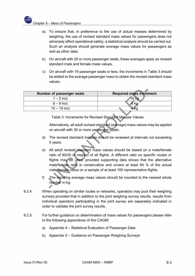
c) On aircraft with 19 passenger seats or less, the increments in Table 3 should be added to the average passenger mass to obtain the revised standard mass values.
Number of passenger seats Required mass increment 1 – 5 incl. 16 kg 6 – 9 incl. 8 kg
10 – 19 incl. 4 kg
Table 3: Increments for Revised Standard Masses Values
Alternatively, all adult revised standard (average) mass values may be applied on aircraft with 30 or more passenger seats.
d) The revised standard masses should be reviewed at intervals not exceeding 5 years.
e) All adult revised standard mass values should be based on a male/female ratio of 80/20 in respect of all flights. A different ratio on specific routes or flights may be used, provided supporting data shows that the alternative male/female ratio is conservative and covers at least 84 % of the actual male/female ratios on a sample of at least 100 representative flights.
f) The resulting average mass values should be rounded to the nearest whole number in kg.
9.2.4 When operating on similar routes or networks, operators may pool their weighing surveys provided that in addition to the joint weighing survey results, results from individual operators participating in the joint survey are separately indicated in order to validate the joint survey results.
9.2.5 For further guidance on determination of mass values for passengers please refer to the following appendices of this CAGM:
a) Appendix 4 – Statistical Evaluation of Passenger Data
b) Appendix 5 – Guidance on Passenger Weighing Surveys

Chapter 9 – Mass of Passengers
Issue 01/Rev 00 CAGM 6805 – AMBP 9-4
INTENTIONALLY LEFT BLANK

Chapter 10 – Mass of Fuel
Issue 01/Rev 00 CAGM 6805 – AMBP 10-1
10 Mass of Fuel (CAD 6805 13)
10.1 CAD 6805 13.1 – Fuel density
10.1.1 If the actual fuel density is not known, the operator may use standard fuel density values for determining the mass of the fuel load. Such standard values should be based on current fuel density measurements for the airports or areas concerned.
10.1.2 RESERVED

Chapter 10 – Mass of Fuel
Issue 01/Rev 00 CAGM 6805 – AMBP 10-2
INTENTIONALLY LEFT BLANK

Chapter 11 – Operator’s Aircraft Mass and Balance Programme (MBP) Approval
Issue 01/Rev 00 CAGM 6805 – AMBP 11-1
11 Operator’s Aircraft Mass and Balance Programme (MBP) Approval (CAD 6805 15)
11.1 CAD 6805 15.4 – MBP approval
11.1.1 The operator should complete and provide to CAAM an Aircraft Mass and Balance Programme Document Compliance Checklist Form No. CAAM/AW/6805-02. The checklist is used to declare compliance to the applicable paragraphs of CAD 6805 and this CAGM prior to the initial approval and for any amendment of the MBP. The compliance declaration should make reference to the associated paragraph in the operator’s MBP document as applicable. The compliance declaration statement should be signed by the CAMO manager (i.e. the personnel accepted pursuant to paragraph 5.1.3 of CAD 6802).

Chapter 11 – Operator’s Aircraft Mass and Balance Programme (MBP) Approval
Issue 01/Rev 00 CAGM 6805 – AMBP 11-2
INTENTIONALLY LEFT BLANK

Chapter 12 – Appendices
Issue 01/Rev 00 CAGM 6805 – AMBP 12-1
12 Appendices
12.1 Appendix 1 – MASS AND BALANCE REPORT (MBR)
1 This Appendix presents a sample MBR.
This Mass and Balance Report supersedes all earlier issues.

Chapter 12 – Appendices
Issue 01/Rev 00 CAGM 6805 – AMBP 12-2
Items included in empty mass:
The datum is at …………………………. This is the datum defined in the Flight Manual. All lever arms are distances in inches /meters aft of datum.

Chapter 12 – Appendices
Issue 01/Rev 00 CAGM 6805 – AMBP 12-3
Note(s):
1. The landing gear position is retracted/extended in relation to the derived CG position
2. The flaps position are in fully extended / retracted position in relation to the derived CG position.

Chapter 12 – Appendices
Issue 01/Rev 00 CAGM 6805 – AMBP 12-4
INTENTIONALLY LEFT BLANK

Chapter 12 – Appendices
Issue 01/Rev 00 CAGM 6805 – AMBP 12-5
12.2 Appendix 2 - MASS AND CENTRE OF GRAVITY SCHEDULE (MCGS)
1 This Appendix presents a sample MCGS.
SAMPLE MCGS
Reference MIJ/3658
Produced by Aero Fly Berhad
Aircraft Designation Eagle1
Nationality and Registration Marks 9M-SAMPLE
Aircraft Type Certificate Holder Eagle Co. Ltd.
Manufacturer’s Serial Number 34454
Maximum Total Mass Authorised 7300 lb
Centre-of-Gravity Limits Refer to Flight Manual reference number 90/946
Part A Empty Mass
The Empty mass of the aircraft as calculated from Mass and Balance Report:
MIJ/W/95 dated 31 August 2019 is : 5516 lb
The CG of the aircraft in the same condition at this mass and with the landing gear extended is : 127 in aft of datum
The total moment about the datum in this condition in lb in/100 is : 7015
The Empty mass includes the mass of 5 gal unusable fuel and 1 gal unusable oil and the mass of the following items which comprise the list of Basic Equipment:
MASS (lb)
LEVER ARM (in)
Two Marzell propeller type BL–H3Z30
Two engine driven 100 ampere alternators type GE–361
One 13 Ah Ni-Cd battery CB–7
Etc.
127 each
27 each
31
Etc.
76
117
153
Etc. Note: The datum is at fuselage station O situated 114 inches forward of the wing leading edge. This is the datum defined in the Flight Manual. All lever arms are distances in inches aft of datum.

Chapter 12 – Appendices
Issue 01/Rev 00 CAGM 6805 – AMBP 12-6
Part B Variable Load
The mass, lever arms and moments of items of Variable Load are shown below. The Variable Load depends upon the equipment carried for the particular role.
MASS (lb)
LEVER ARM (in)
MOMENT (100 lb in)
Pilot (one)
De-icing fluid 1.5 gal
Life-jackets (7)
Row 1 passenger seats (two)
Row 2 passenger seats (two)
Row 3 passenger seats (two)
Table
One stretcher and attachments (in place of seat rows 2 and 3)
Medical stores
12
14
60
60
60
8
45
15
108
140
135
173
215
248
256
223
250
17
19
104
129
149
20
100
37
Part C Loading Information (Disposable Load)
The total moment change when the landing gear is retracted in lb in/100 is: –18.
The appropriate lever arms are:
MASS (lb)
LEVER ARM (in)
CAPACITY (Imp. gal)
Fuel in tanks 1 and 2
Engine Oil
Forward baggage
Rear baggage
Passengers in Row 1 seats
Passengers in Row 2 seats
Passengers in Row 3 seats
13681
501
145
70
21
261
171
213
246
190
5.5

Chapter 12 – Appendices
Issue 01/Rev 00 CAGM 6805 – AMBP 12-7
Patient in stretcher 223 Note: To obtain the total loaded mass of aircraft, add to the Empty mass the mass of the items of Variable and Disposable Load to be carried for the particular role.
1. Densities – Petrol 7.2 lb Imp. gal; Kerosone 8.1 Ib Imp. gal; Oil 9.0 Ib Imp. gal.
It is a requirement of the MCAR that the pilot-in-command satisfies himself before take-off that the load is of such mass, and is so distributed and secured, that it may safely be carried on the intended flight.
This MCGS was prepared on (date) .......... and supersedes all previous issues.
Signed ....................................... (MCGS signatory)
on behalf of ............................................................ (Operator)
Approval Reference ................................................
Chapter 12 – Appendices
Issue 01/Rev 00 CAGM 6805 – AMBP 12-8
INTENTIONALLY LEFT BLANK
Chapter 12 – Appendices
Issue 01/Rev 00 CAGM 6805 – AMBP 12-9
12.3 Appendix 3 - ADJUSTMENT OF STANDARD MASSES
1 When standard mass values are used, CAGM paragraph 9.1.5 states that the operator should identify and adjust the passenger masses in cases where significant numbers of passengers are suspected of significantly deviating from the standard values. Therefore, the operations manual and MBP document should contain instructions to ensure that:
a) check-in, operations and cabin staff and loading personnel report or take appropriate action when a flight is identified as carrying a significant number of passengers whose masses, including hand baggage, are expected to significantly deviate from the standard passenger mass, and/or groups of passengers carrying exceptionally heavy baggage (e.g. military personnel or sports teams); and
b) on small aircraft, where the risks of overload and/or CG errors are the greatest, pilots pay special attention to the load and its distribution and make proper adjustments.

Chapter 12 – Appendices
Issue 01/Rev 00 CAGM 6805 – AMBP 12-10
INTENTIONALLY LEFT BLANK

Chapter 12 – Appendices
Issue 01/Rev 00 CAGM 6805 – AMBP 12-11
12.4 Appendix 4 - STATISTICAL EVALUATION OF PASSENGERS DATA
1 Sample size
a) For calculating the required sample size, it is necessary to make an estimate of the standard deviation on the basis of standard deviations calculated for similar populations or for preliminary surveys. The precision of a sample estimate is calculated for 95 % reliability or ‘significance’, i.e. there is a 95 % probability that the true value falls within the specified confidence interval around the estimated value. This standard deviation value is also used for calculating the standard passenger mass.
b) As a consequence, for the parameters of mass distribution, i.e. mean and standard deviation, three cases have to be distinguished:
1) μ, σ = the true values of the average passenger mass and standard deviation, which are unknown and which are to be estimated by weighing passenger samples.
2) μ’, σ’ = the ‘a priori’ estimates of the average passenger mass and the standard deviation, i.e. values resulting from an earlier survey, which are needed to determine the current sample size.
3) x̅, s = the estimates for the current true values of average passenger mass and standard deviation, calculated from the sample.
The sample size can then be calculated using the following formula:
𝑖𝑖 ≥ (1.96 ∗ 𝜎𝜎′ ∗ 100)2
(𝑖𝑖𝑟𝑟′ ∗ 𝜇𝜇′)2
where:
n = number of passengers to be weighed (sample size)
e’r = allowed relative confidence range (accuracy) for the estimate of μ by x̅ (see also equation in (c)). The allowed relative confidence range specifies the accuracy to be achieved when estimating the true mean. For example, if it is proposed to estimate the true mean to within ±1 %, then e’r will be 1 in the above formula.
1.96 = value from the Gaussian distribution for 95 % significance level of the resulting confidence interval.
2 Calculation of average mass and standard deviation. If the sample of passengers weighed is drawn at random, then the arithmetic mean of the sample (x̅) is an unbiased estimate of the true average mass (μ) of the population.
a) Arithmetic mean of sample where:
�̅�𝑖 =∑ 𝑥𝑥𝑗𝑗𝑛𝑛𝑗𝑗=1
𝑛𝑛

Chapter 12 – Appendices
Issue 01/Rev 00 CAGM 6805 – AMBP 12-12
xj = mass values of individual passengers (sampling units).
b) Standard deviation where:
𝑆𝑆 = �∑ (𝑖𝑖𝑗𝑗 − �̅�𝑖)2 𝑛𝑛𝑗𝑗=1
𝑖𝑖 − 1
xj – x̅ = deviation of the individual value from the sample mean.
3 Checking the accuracy of the sample mean. The accuracy (confidence range) which can be ascribed to the sample mean as an indicator of the true mean is a function of the standard deviation of the sample which has to be checked after the sample has been evaluated. This is done using the formula:
𝑖𝑖𝑟𝑟 = 1.96 ∗ 𝑆𝑆 ∗ 100
√𝑖𝑖 ∗ �̅�𝑖 (%)
whereby er should not exceed 1% for an all adult average mass and 2% for an average male and/or female mass. The result of this calculation gives the relative accuracy of the estimate of μ at the 95 % significance level. This means that with 95% probability, the true average mass μ lies within the interval:
�̅�𝑖 ± 1.96 ∗ 𝑆𝑆√𝑖𝑖
4 Example of determination of the required sample size and average passenger mass
a) Introduction. Standard passenger mass values for mass and balance purposes require passenger weighing programs to be carried out. The following example shows the various steps required for establishing the sample size and evaluating the sample data. It is provided primarily for those who are not well versed in statistical computations. All mass figures used throughout the example are entirely fictitious.
b) Determination of required sample size. For calculating the required sample size, estimates of the standard (average) passenger mass and the standard deviation are needed. The ‘a priori’ estimates from an earlier survey may be used for this purpose. If such estimates are not available, a small representative sample of about 100 passengers should be weighed so that the required values can be calculated. The latter has been assumed for the example.
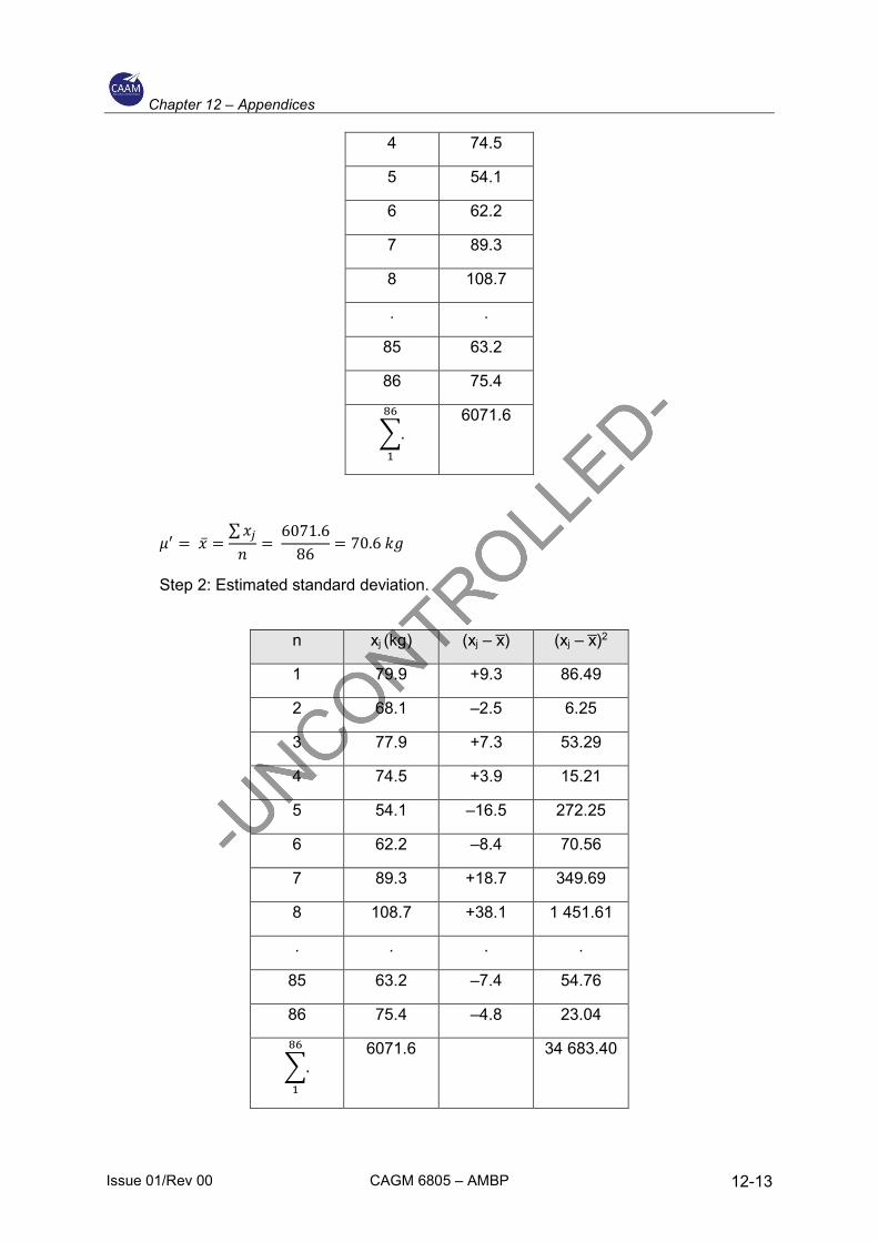
Step 1: Estimated average passenger mass.
n xj (kg)
1 79.9
2 68.1
3 77.9
Chapter 12 – Appendices
Issue 01/Rev 00 CAGM 6805 – AMBP 12-13
4 74.5
5 54.1
6 62.2
7 89.3
8 108.7
. .
85 63.2
86 75.4
�.86
1
6071.6
𝜇𝜇′ = �̅�𝑖 =∑𝑖𝑖𝑗𝑗𝑖𝑖
= 6071.6
86= 70.6 𝑘𝑘𝑤𝑤
Step 2: Estimated standard deviation.
n xj (kg) (xj – x̅) (xj – x̅)2
1 79.9 +9.3 86.49
2 68.1 –2.5 6.25
3 77.9 +7.3 53.29
4 74.5 +3.9 15.21
5 54.1 –16.5 272.25
6 62.2 –8.4 70.56
7 89.3 +18.7 349.69
8 108.7 +38.1 1 451.61
. . . .
85 63.2 –7.4 54.76
86 75.4 –4.8 23.04
�.86
1
6071.6 34 683.40

Chapter 12 – Appendices
Issue 01/Rev 00 CAGM 6805 – AMBP 12-14
σ’ = �∑ (𝑖𝑖𝑗𝑗 − �̅�𝑖)2
𝑖𝑖 − 1
σ’ = �34683.40
86 − 1
σ’= 20.20 kg
Step 3: Required sample size.
The required number of passengers to be weighed should be such that the confidence range, e'r does not exceed 1%, as specified in 3.
𝑖𝑖 ≥ (1.96 ∗ 𝜎𝜎′ ∗ 100)2
(𝑖𝑖𝑟𝑟′ ∗ 𝜇𝜇′)2
𝑖𝑖 ≥ (1.96 ∗ 20.20 ∗ 100)2
(1 ∗ 70.6)2
𝑖𝑖 ≥ 3145
The result shows that at least 3145 passengers should be weighed to achieve the required accuracy. If e’r is chosen as 2% the result would be n ≥ 786.
Step 4: After having established the required sample size, a plan for weighing the passengers is to be worked out.
c) Determination of the passenger average mass
Step 1: Having collected the required number of passenger mass values, the average passenger mass can be calculated. For the purpose of this example, it has been assumed that 3180 passengers were weighed. The sum of the individual masses amounts to 231186.2 kg.
n = 3180
� 𝑖𝑖𝑗𝑗 = 231186.2 𝑘𝑘𝑤𝑤3180
𝑗𝑗=1
�̅�𝑖 =∑𝑖𝑖𝑗𝑗𝑖𝑖
=231186.2
3180 𝑘𝑘𝑤𝑤
�̅�𝑖 = 72.7 𝑘𝑘𝑤𝑤
Step 2: Calculation of the standard deviation
For calculating the standard deviation, the method shown in paragraph (b) step 2 should be applied.

Chapter 12 – Appendices
Issue 01/Rev 00 CAGM 6805 – AMBP 12-15
� (𝑖𝑖𝑗𝑗 − �̅�𝑖)2 = 745145.20
𝑠𝑠 = �∑ (𝑖𝑖𝑗𝑗 − �̅�𝑖)2
𝑖𝑖 − 1
𝑠𝑠 = �745145.203180 − 1
𝑠𝑠 = 15.31 𝑘𝑘𝑤𝑤
Step 3: Calculation of the accuracy of the sample mean
𝑖𝑖𝑟𝑟 = 1.96 ∗ 𝑠𝑠 ∗ 100
√𝑖𝑖 ∗ �̅�𝑖 %
𝑖𝑖𝑟𝑟 = 1.96 ∗ 15.31 ∗ 100√3180 ∗ 72.7
%
𝑖𝑖𝑟𝑟 = 0.73 %
Step 4: Calculation of the confidence range of the sample mean
�̅�𝑖 ± 1.96 ∗ 𝑠𝑠√𝑖𝑖
�̅�𝑖 ± 1.96 ∗ 15.31√3180
𝑘𝑘𝑤𝑤
72.7 ± 0.5 𝑘𝑘𝑤𝑤
The result of this calculation shows that there is a 95% probability of the actual mean for all passengers lying within the range 72.2 kg to 73.2 kg.

Chapter 12 – Appendices
Issue 01/Rev 00 CAGM 6805 – AMBP 12-16
INTENTIONALLY LEFT BLANK

Chapter 12 – Appendices
Issue 01/Rev 00 CAGM 6805 – AMBP 12-17
12.5 Appendix 5 - GUIDANCE ON PASSENGER WEIGHING SURVEYS
1 Detailed survey plan
a) The operator should establish and submit to the CAAM a detailed weighing survey plan that is fully representative of the operation, i.e. the network or route under consideration and the survey should involve the weighing of an adequate number of passengers.
b) A representative survey plan means a weighing plan specified in terms of weighing locations, dates and flight numbers giving a reasonable reflection of the operator’s timetable and/or area of operation.
c) The minimum number of passengers to be weighed is the highest of the following:
1) The number that follows from the means of compliance that the sample should be representative of the total operation to which the results will be applied; this will often prove to be the overriding requirement.
2) The number that follows from the statistical requirement specifying the accuracy of the resulting mean values, which should be at least 2% for male and female standard masses and 1% for all adult standard masses, where applicable. The required sample size can be estimated on the basis of a pilot sample (at least 100 passengers) or from a previous survey. If analysis of the results of the survey indicates that the requirements on the accuracy of the mean values for male or female standard masses or all adult standard masses, as applicable, are not met, an additional number of representative passengers should be weighed in order to satisfy the statistical requirements.
d) To avoid unrealistically small samples, a minimum sample size of 2000 passengers (males + females) is also required, except for small aircraft where in view of the burden of the large number of flights to be weighed to cover 2000 passengers, a lesser number is considered acceptable.
2 Execution of weighing programme
a) At the beginning of the weighing programme, it is important to note, and to account for, the data requirements of the weighing survey report (see (e)).
b) As far as is practicable, the weighing programme should be conducted in accordance with the specified survey plan.
c) Passengers and all their personal belongings should be weighed as close as possible to the boarding point and the mass, as well as the associated passenger category (male/female/child), should be recorded.
3 Analysis of results of weighing survey. The data of the weighing survey should be analysed as explained in this Appendix. To obtain an insight to variations per flight, per route, etc. this analysis should be carried out in several stages, i.e. by flight, by route, by area, inbound/outbound, etc. Significant deviations from the weighing survey plan should be explained as well as their possible effect(s) on the results.

Chapter 12 – Appendices
Issue 01/Rev 00 CAGM 6805 – AMBP 12-18
4 Results of the weighing survey
a) The results of the weighing survey should be summarised. Conclusions and any proposed deviations from published standard mass values should be justified. The results of a passenger weighing survey are average masses for passengers, including hand baggage, which may lead to proposals to adjust the standard mass values given in Table 2. These averages, rounded to the nearest whole number may, in principle, be applied as standard mass values for males and females on aircraft with 20 or more passenger seats. Because of variations in actual passenger masses, the total passenger load also varies and statistical analysis indicates that the risk of a significant overload becomes unacceptable for aircraft with less than 20 seats. This is the reason for passenger mass increments on small aircraft.
b) The average masses of males and females differ by some 15 kg or more. Because of uncertainties in the male/female ratio, the variation of the total passenger load is greater if all adult standard masses are used than when using separate male and female standard masses. Statistical analysis indicates that the use of all adult standard mass values should be limited to aircraft with 30 passenger seats or more.
c) Standard mass values for all adults must be based on the averages for males and females found in the sample, taking into account a reference male/female ratio of 80/20 for all flights. The operator may, based on the data from his weighing programme, or by proving a different male/female ratio, apply for approval of a different ratio on specific routes or flights.
5 Weighing survey report
The weighing survey report, reflecting the content of 4, should be prepared in a standard format as follows:

Chapter 12 – Appendices
Issue 01/Rev 00 CAGM 6805 – AMBP 12-19
WEIGHING SURVEY REPORT
1 Introduction
Objective and brief description of the weighing survey.
2 Weighing survey plan
Discussion of the selected flight number, airports, dates, etc.
Determination of the minimum number of passengers to be weighed.
Survey plan.
3 Analysis and discussion of weighing survey results
Significant deviations from survey plan (if any).
Variations in means and standard deviations in the network.
Discussion of the (summary of) results.
4 Summary of results and conclusions
Main results and conclusions.
Proposed deviations from published standard mass values.
Attachment 1
Applicable summer and/or winter timetables or flight programmes.
Attachment 2
Weighing results per flight (showing individual passenger masses and gender); means and standard deviations per flight, per route, per area and for the total network.