civil 3d survey workflow
TRANSCRIPT

Survey Overview for Civil3D
May 31, 2013
Index
Start a new PEDDS project - Item 1
Start a new project without using PEDDS – Item2
Create a working drawing – Item 3
Create a survey database – Item4
Import Survey Database 1. (ASCII Control Points) – Item 5
Manage data with LandXML Grouper – Item 6
Import Survey Database 2. (Windows EFB or Caice Data) – Item 7
Clean-UP – Item 8
Alignment – Item 9
Alignment from a Caice Project (Method 1) – Item 10
Other Geometry Chains from Caice – Item 11
Alignment from a Caice Project (Method 2) – Item 12
Alignment text file – Item 13
GDTMRD Surface – Item 14
Compliant GDTMRD – Item 15
Check Cross Sections – Item 16
Compliant Bridge GDTMRD – Item 17
Compliant TOPORD – Item 18
Compliant DREXRD – Item 19
Compliant UTEXRD – Item 20
Compliant CTLSRD – Item 21
Pipe Networks – Item 22

1. Start a new PEDDS project.
FDOT2012.C3D - CreateProjectC3D –

Items in RED must be filled out! When it turns Green it will be accepted.
This information is used to fill out sheet information in paper space later in the process. Even though we work for Survey in-house which would be 3101 fill it out using 5 for the Phase Group, 2 for the Phase Type and 01 for the Sequence.
Click on finish. You get a verification box just click OK. A new PEDDS XML Editor box appears and you can make additional changes but the most important TAB is the Disciplines box. I would place a check in the boxes shown next as I don’t know how to change these settings later.

Click next a couple of times and then finish. You then get a box showing changes were saved just click OK.
You get another box at this point saying the project information has been modified and updating Master SheetSet Template. Just click OK. This opens Civil3D and updates and then closes leaving you with another box saying the Master SheetSet Template Successfully Updated. Just click OK. This brings up a New Project Summary Report that you can review and close. You then get another box saying your project was created. Just click OK. Close the PEDDS – ProjectId XML Editor box if it hadn’t already closed.
2. Start a new project without using PEDDS.
This can be done, however it is not advised due to certain XML files that fill out title blocks and for tracking in log files.
3. Create a working drawing.

The first drawing in the project should be a catch-all, SURVRD01.DWG. Other files for the project can be made inside Civil3D but to get started do this.
FDOT2012.C3D - Create Files
When this box comes up the first thing is to select the project. I don’t know why it doesn’t remember the project you just created.

Click Create File – Then click Open File.
Use ALT-TAB and close the Create File box.
In the workspace at the top make sure you are in Civil3D workspace.
Home-Toolspace-Settings right click TOPORD Edit Drawing Settings. Set the appropriate state plane co-ordinate system. The example below is for District 3. It is better to use the NAD83 instead of HARN in order to match other settings in Civil3D where HARN is not available.
Click OK.
Save

4. Create a survey database
Toolspace –Survey
Right click on Survey Database – Set Working folder then Browse to C:\Civil3DProjects\currentprojectNo\survey then click OK.
Right click on Survey Database – New local survey database then enter a 7 digit FP# for the name.
Right click on this 7 digit FP# under Survey Databases in Toolspace and select Edit survey database settings.
or
Click the extreme top left button under the word Toolspace to edit the Survey Database Settings and change the Survey Database Settings under Survey Database Defaults to the appropriate state plane co-ordinate system. The example below is for District 3.

Close Box and save.

5. Import Survey Database 1. (ASCII Control Points)
Prepare to import file
Using MS Excel copy and paste in point values from GPS and Level processing. Column A = Point name, Column B = Northing, Column C = Easting, Column D = Elevation, Column E = Description for each point. Save the file as a CSV (comma delimited) (* .csv) file in your C:\Civil 3DProjects\11digit FP#\survey\7 digit FP# folder (your survey database folder).
Right click on this file and open with Notepad. Delete the “at the beginning and end of the descriptions. Delete any extra “inside descriptions. Don’t worry and leave the “mark indicating inches inside the description. Then save the file and close.
The first time you import this type of file you need to set up this type of file in Civil3D as follows:
Toolspace – Survey – Survey Databases –7digitFP#
Right click Import Events – Import survey data Select 7digitFP# database – Next – Select Point file. Click the button Manage Formats –then New- then User Point File OK. Name the file FDOTCSV- Default Extension = .csv – Delimited by, - unused left – Name –next unused Northing – next unused Easting – next unused Point Elevation – next unused Raw Description. Click OK.

This format will be saved and you shouldn’t need to do this again unless you change formats. I am looking to add Zones and Feature Codes to this input.
Import file
Toolspace – Survey – Survey Databases –7digitFP#
Right click Import Events – Import survey data Select 7digitFP# database – Next – Select Point file. Click on the + (Add Files) button ad browse to the csv file created in the survey database. It should recognize the D3CSV format. Then click Next – Then Next again since we do not have a Network – Then click Finish.
Save

6. Manage data with LandXML Grouper.
FDOT – Tools – LandXML Grouper or C:\FDOT2012.C3D\APPS\LandXMLGrouper \LandXMLGrouper.exe
Open a LandXML file that needs to be grouped. You will need to do this in order to edit the groups and settings.
Suggested grouper set-up.
Right click and unlock the category and set them up as follows:
a. TOPORD Chains feature code driven only. Remove BL, BLC, REFL, XS and XSC b. TOPORD Points feature code driven only. Remove BL, BLC, XS and XSC c. DREXRD Chains feature code driven only d. DREXRD Points feature code driven only e. UTEXRD Chains feature code driven zone 3 only f. UTEXRD Points feature code driven zone 3 only g. GDTMRD Chains Zones 1 & 2 Ground h. GDTMRD Points Zones 1 & 2 Ground

i. Bridge_DTM Chains Zone 4 Ground j. Bridge_DTM Chains Zone 4 Ground k. ROW_Control_Survey Points feature code driven only l. ROW_Topo Points feature code driven only m. Control_Points Survey points in zone 5 n. XSection_Chains Zone 7 only o. XSection_Points Zone 7 only p. Control_Chains Chains in zone 5 Use only if you copied reference line geometry chains
in Caice to survey chains before making the LandXML file.
If any of these categories are missing right click on “Name” and add filter and name then edit as suggested above.
When finished with all of the edits above Filters – Export and give a name such as FDOTGroupFiltersD3.xml
7. Import Survey Database 2. (Windows EFB or Caice Data)
FDOT – Tools – LandXML Grouper
Filters – Import – File and browse to the file created above (FDOTGroupFiltersD3.xml)
File – Open – Browse to LandXML file – Open.
Select all filters and right click in order to Create Groups.
Look at GTMRD Points and make note of any points without elevations. These can be handled inside Civil3d, but it might be easier to correct in WindowsEFB or Caice and remake the LandXML file.
Save as a Grouper LandXML file as example 4304301-Grouped.xml
Close the box.
Toolspace – Survey – Survey Databases –7digitFP#
Right click 7digitFP# database – Import – Import Survey LandXML - Browse- Click on 7 digit FP# - Save
Right click on GDTMRD Points –Properties uncheck points noted above that don’t have elevations.
8. Clean-UP:

To edit a chain as we call it click on the chain to highlight then right click on a handle pick edit figure features properties.
9. Alignment:
Right click on the icons on the right of the co-ordinates box at the bottom of the workspace and un-check the show icons box in order to see text instead of icons. Then right click on the OSNAP button – settings and check the Endpoint, Center, Node, Intersection, and Extension boxes - OK
Set points for building alignment such as extending and intersecting P.I.s of tangents. Use the line command to make lines on tangents. Extend these lines and set points at intersections using the point creation tools.
Use the Polyline command (Home-Draw – PolyLine) and draw a line in the direction you want the stations to go from the beginning station through curves and to the end of survey.
Home- Create Design - Alignment – Create Alignment from Objects.

Uncheck the box Add curves between tangents.
In order to view the stations change the scale to about 1”=50’ at the bottom of the page.
Save
Additional information from Mary Peterman:
Creating Alignments
Creating Points at Intersection.

Note the following command will create Cogo points without the need to extend lines, it interpolates the extension from selecting Entities (tangent lines). You can select figures, lines, polylines to project. The points can be used for a target points for polylines or alignment creation. It was not clear to me if this was the command mentioned.
Creating Alignment by Layout instead of Object eliminates the step for polylines. Result is the same as when you create an object and as easy.
10. Alignment from a Caice Project Method 1:
In Caice with the project active Geometry- Geometry Chains – Edit Horizontal Alignment
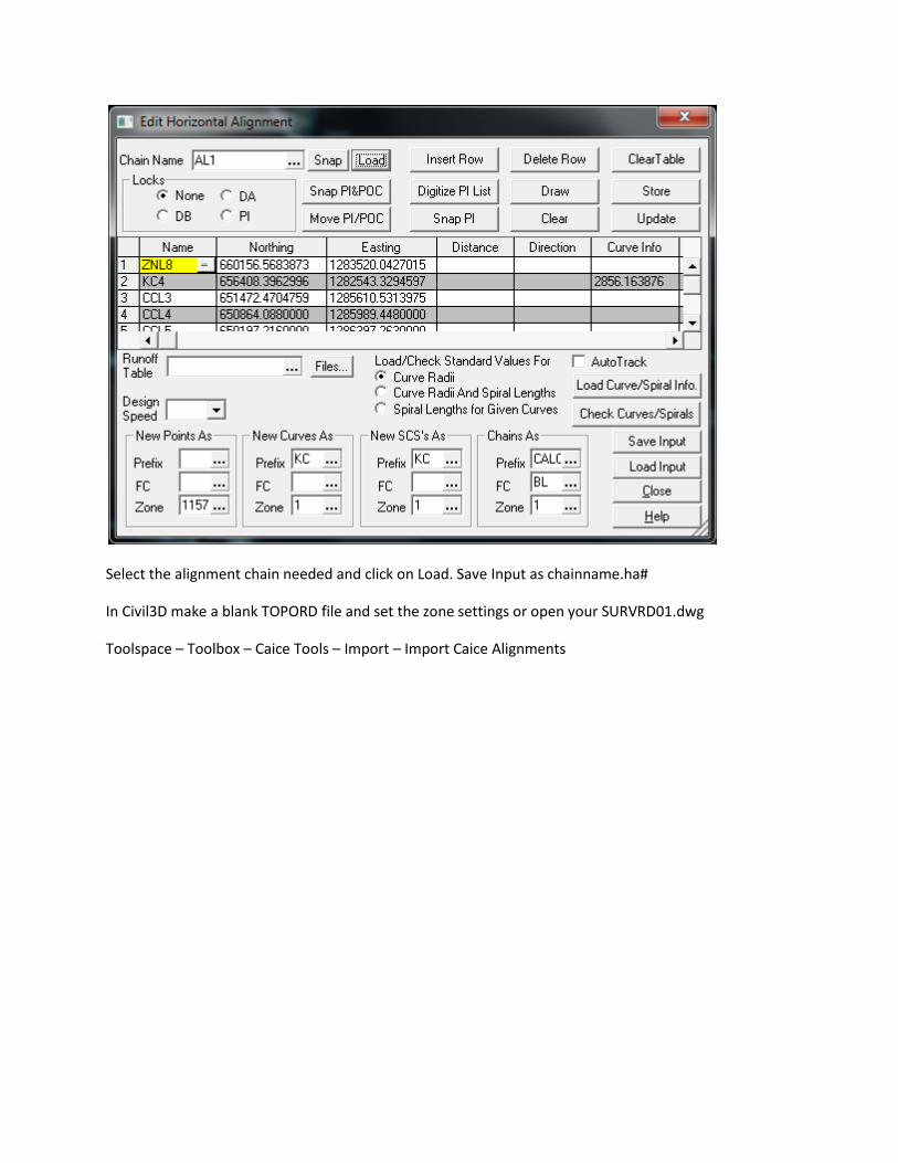
Select the alignment chain needed and click on Load. Save Input as chainname.ha#
In Civil3D make a blank TOPORD file and set the zone settings or open your SURVRD01.dwg
Toolspace – Toolbox – Caice Tools – Import – Import Caice Alignments

Change Type to Centerline
Change Layer to BLSurveyField_ep.
Set stationing display.
Ok
11. Other Geometry Chains from Caice:
This will get the other geometry chains from Caice that you might need. This will get the right of way lines, section and quarter section lines, reference lines, subdivision lines and about any geometry chain

that is not an alignment. The only drawback to this method is that you need to do these one at a time. You cannot do say a REF* and get all reference point lines.
In Caice with the project active Geometry- Geometry Chains – Edit Horizontal Alignment
Select the geometry chain needed and click on Load. Save Input as chainname.ha#
Repeat this step for each and every geometry chain you will need.
In Civil3D make a blank SURVRD file and set the zone settings or open your SURV01.dwg
Toolspace – Toolbox – Caice Tools – Import – Import Caice Alignments

Change Type to Miscellaneous
Change Layer to what is appropriate
Alignment label is set to _No Labels
Ok
12. Alignment from a Caice Project Method 2:
Create a blank SURVRD file using the survey.dwt template.

Set the zone settings.
This file is just a throw-away to extract data from.
ToolBox – Caice Tools – Right click Import Caice Project (*pt4) - Execute. Browse for the project - Open.
Use the select all –
Next
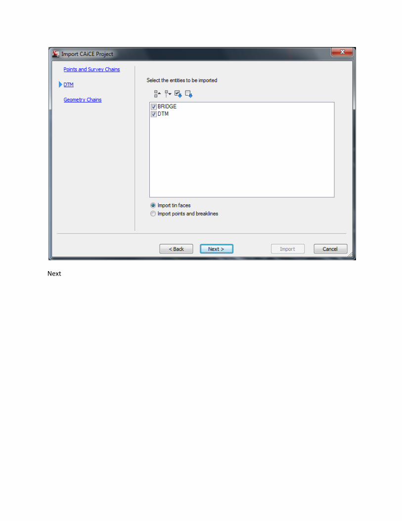
Next

Import.
Toolspace – Alignments – Right click Centerline Alignments- Export LandXML – OK.
Save as Alignment.xml. Open your TOPORD file and Insert LandXml. Highlight the alignment –right click –properties and change the level to BLSurveyField_ep. Set scale at the bottom of the screen to 1”=40’ to see the stationing.
As you can see this also gets other geometry lines such as section, property, and reference lines. Find out how to extract these to LandXML too. Doug Medley says you can export using a LandXML, but I haven’t figured this out yet. It don’t work for me.
13. Alignment text file:
Toolspace – Toolbox – Reports Manager Click the extreme left button under the word Toolspace at the top of the toolspace box. Fill out the company information under owner.

Toolspace – Toolbox – Reports Manager – Alignment – double click on Station and Curve.

Uncheck everything except Alignments.

Change output to txt file and Name Align.txt and save in \11digitFP#\Survey
14. GDTMRD Surface:
FDOT – Create File (use survey design files GDTMRD)
Home-Toolspace-Settings right click GDTMRD Edit Drawing Settings. Set the appropriate state plane co-ordinate system.
Toolspace – Prospector – Right click on Surface – Create Surface

Name the surface EXIST.
Change the layer to DTMTriangles_ep.
Click OK - OK
Toolspace – Survey – 7digitFP# - Survey Point Groups – Right Click GDTMRD Points - Insert Into the drawing.
Toolspace – Survey – 7digitFP# - Figure Groups – Right Click GDTMRD Chains - Insert Into the drawing.
Toolspace – Prospector – Surfaces – Active Surface – Definition - Right click Point Groups – Add GDTMRD Points.
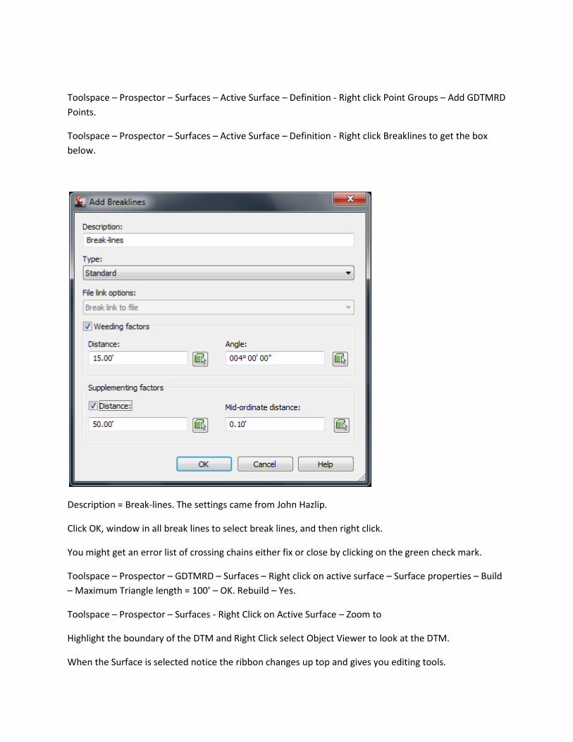
Toolspace – Prospector – Surfaces – Active Surface – Definition - Right click Breaklines to get the box below.
Description = Break-lines. The settings came from John Hazlip.
Click OK, window in all break lines to select break lines, and then right click.
You might get an error list of crossing chains either fix or close by clicking on the green check mark.
Toolspace – Prospector – GDTMRD – Surfaces – Right click on active surface – Surface properties – Build – Maximum Triangle length = 100’ – OK. Rebuild – Yes.
Toolspace – Prospector – Surfaces - Right Click on Active Surface – Zoom to
Highlight the boundary of the DTM and Right Click select Object Viewer to look at the DTM.
When the Surface is selected notice the ribbon changes up top and gives you editing tools.

From Mary Peterman:
Surface create build options, layers etc. can also be preset so these details can optionally be removed from the workflow when in the template.
15. Compliant GDTMRD:
When satisfied with the DTM Toolspace – Prospector – Surfaces - right click on the active surface and select Export to LandXml file. Save in the survey folder of the active project.
FDOT – Create File (use survey design files GDTMRD)
Home-Toolspace-Settings right click GDTMRD Edit Drawing Settings. Set the appropriate state plane co-ordinate system.
Insert - LandXML
John K. Hazlip, PSM
Save
16. Check Cross Sections:
Open a copy of the Compliant GDTMRD file – Import the Align.xml file.
Toolspace – Survey – Active database – Survey Point Groups-Right click on X-Section Points – Insert into Drawing
Toolspace – Survey – Active database – Figure Groups -Right click on XSection Chains – Insert into Drawing

Click on a cross section chain and notice the ribbon up top changes. Click on Quick Profile and select the chain.
Change the Profile view style to FDOT as shown above. Click ok and you get a box telling you the view will be only temporary. Close this box and pick a point where you want the profile to be displayed. If we could only get this to show elevations we would have the check section part of this knocked, but for now graphically will do.
From Mary Peterman:
I am not familiar with the output desired. If you need a ‘permanent’ profile view of the chains, explode them to polyline, convert to alignment and create a permanent surface profile along the ‘chain’ alignment.
Quick profile will not show Survey Points.
A new style for the desired profile view can be set to show elevations if that is where they need to be.
Answer:
A simple text file would do that showed the distance right or left of the centerline with elevations at the break points. This file could be used to compare the results of the DTM with a sample line taken at the same station as the check cross sections. The field cross sections could be digital or in a field book for

comparison. In Caice you can make a .ssr file that is equal to the old RTF format that shows this graphically as well.
17. Compliant Bridge GDTMRD:
This is like a regular DTM, except you need to make a group to start with.
Toolspace – Prospector – Right click on Surface – Create Surface
Name the surface Bridge.
Change the layer to DTMTriangles_ep.

Click OK – OK
Toolspace right click Survey Point Groups – New- Name Bridge Points Right click – Properties and add items in the bridge elements bridge zone. You may need to rely on point names of BRDG.
Toolspace right click Figure Groups – New- Name BridgeDTM Click Site and add items in the bridge elements bridge zone.
Click on the new group and click yes as to breakline. Right click on the new group and create breaklines.

OK
Save
From Mary Peterman:
Survey figure prefix for brdg can be set to automatically set to be breakline type if desired.
18. Compliant TOPORD:
With your working drawing open using the FDOT ribbon create another TOPORD drawing using the proper topord.dwt template. Create – Open - Close Box.
Home-Toolspace-Settings right click TOPORD Edit Drawing Settings. Set the appropriate state plane co-ordinate system.

Toolspace – Survey – Open Survey database for Edit.
Toolspace – Survey – 7digitFP# - Figure Groups – right click TOPORD Chains – Insert into drawing.
Toolspace – Survey – 7digitFP# - Survey Point Groups – right click TOPORD Points – Insert into drawing.
Save
19. Compliant DREXRD:
With your working drawing open using the FDOT ribbon create a DREXRD drawing. Create – Open - Close Box.
Home-Toolspace-Settings right click DREXRD Edit Drawing Settings. Set the appropriate state plane co-ordinate system.
Toolspace – Survey – Open Survey database for Edit.
Toolspace – Survey – 7digitFP# - Figure Groups – right click DREXRD Chains – Insert into drawing.
Toolspace – Survey – 7digitFP# - Survey Point Groups – right click DREXRD Points – Insert into drawing.
Save
20. Compliant UTEXRD:
With your working drawing open using the FDOT ribbon create a UTEXRD drawing. Create – Open - Close Box.
Home-Toolspace-Settings right click DREXRD Edit Drawing Settings. Set the appropriate state plane co-ordinate system.
Toolspace – Survey – Open Survey database for Edit.
Toolspace – Survey – 7digitFP# - Figure Groups – right click UTEXRD Chains – Insert into drawing.
Toolspace – Survey – 7digitFP# - Survey Point Groups – right click UTEXRD Points – Insert into drawing.
Save
21. Compliant CTLSRD:

From Mary Peterman:
Compliant CTLSRD -The Sheet Set Manager Steps should really be after you create the CTLSRD drawing file and have saved that file per instructions on p.41. (since the file’s layout is added per instruction screenshot on) This order works if the file is saved after the xml info imported, but is a little out of the ‘normal’ AutoCAD sequence.
I thought I did this exactly as shown to me by John Hazlip. I will get him to look this over and help me with changes.
First Toolspace – Active Drawing – Right Click on Alignments – Export to Landxml – OK and save in /11digitFP#/Survey as Align.xml. This is to be used later.
Create a CTLSRD file using the FDOT – Create File and set co-ordinate zone settings. Save

Home – Palettes – Sheet Set Manager – Open – New Sheet Set.
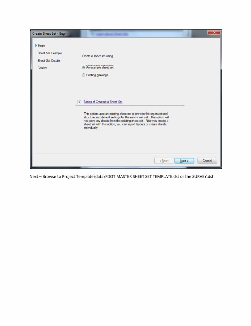
Next – Browse to Project Template\data\FDOT MASTER SHEET SET TEMPLATE.dst or the SURVEY.dst

Next

Name the sheet and store in the eng_data folder under the survey folder in the project. – Next – Finish

Right click on Sheet Set Name and fill out the missing Information for County, District, POR1-8, Project Description and Road Number.


Right click on sheet name in Sheet Set Manager - Import Layout as Sheet

Browse for Drawing and Import checked.
Right Click on Layout name - Properties

Change Sheet Title and Sheet numbers – ok
Type RE in the command line to REGENERATE.
Save

Right click on the TABS at the bottom of the workspace and delete unwanted sheets.
Click on Model
Insert – LandXML and browse to the Align.xml created above - Open
Toolspace – Survey – Active Database – Survey Point Groups – Right Click on Control Points – Insert into Drawing
Toolspace – Toolbox – Reports Manager – Points - Double Click on Station Offsets to Points.

Click on the Save report to button and make a path to your survey folder and change the type of document to txt. Name the document Control.txt

Click the Save button and on the original box click Create Report. Then done.
Unlock View Port – Model Space – xref a file or draw in viewport.
Question from Mary Peterman:
What is being xref’d or drawn in the unlocked viewport?
My answer:
The control sheets in district 3 and I think district 2 uses the top portion to draw the reference line sketches. I was thinking you could reference in a file that had the centerline, reference point lines and reference points in order to copy from and to make these sketches.
22. Pipe Networks:
Question from Mary Peterman:
Who, Survey or Design, will convert the figures into the needed Civil 3D pipe networks for existing utilities and drainage? This is really what is needed for use for the Civil 3D workflows. The points would not be needed.

My Answer is that as a land surveyor I feel that I would be encroaching in an engineering area and that this activity would be better handled on the design end. The existing DREXRD and UTEXRD provided by survey should be sufficient.
Miscellaneous:
To import styles into a drawing: Manage – Styles - Import
Commands:
Re regenerates drawing
Ze zoom extents
3DConfig uncheck hardware acceleration to fix Hidi driver problem.
Software additions:
civil3d_2012_caice_64bit_english.exe for the Caice tools.
Drexrd, survey, topord, utexrd dated March 2013.
Attached are the drainage, topography and utilities templates that will be in the upcoming release of FDOT2012. Keep these handy for our Goto Meeting Thursday and if someone else from your district is attending please forward this to them. These templates have blocks that were specifically designed to visualize and plot as point objects. I will also send after this the survey.dwt which contains the same blocks. If you don’t have the latest version of Civil 3D, don’t worry about it what you have will suffice to get the points across… (pun there somewhere). Also I am going to sent you a video done by Steve Mar. I will have to FTP it to you. It is a couple of years old but still very applicable and informative. Let me know if you have any questions or comments, John K. Hazlip, PSM