city station concourse instructions for assembly of the ho
TRANSCRIPT

City Station ConcourseInstructions for Assembly of the HO scale kit v1.4
Kit Contents:
27 ea. Loose Laser cut .120 acrylic parts
24 ea. Loose Laser cut .060 acrylic parts
20 ea. Sheets of Laser cut .060 acrylic parts
4 ea. Printed floor
4 ea. Double-sided adhesive backing
2 ea. Window Glazing
Instructions with diagrams
Thank you for purchasing this kit. Please read these instructions completely before beginning and
take your time. Allow parts to dry after painting or gluing and do not try to build this in one day.
You will need the following items to assemble your model: Hobby knife, fine sand paper, file,
paint (see “Painting Your Model”), paint brushes, glue (see “Gluing Acrylic”), modeling putty.
Drawings of all the parts are included for identification.
Practice gluing the acrylic together if you have never done it before.
Dry fit (test fit without glue) all the parts prior to assembly. Some of the parts fit behind others so
the order of assembly is critical.
If a part is missing or broken, please email us indicating the kit name, scale, and part number and
we will send you a replacement at: [email protected]
Please note: Parts of the kit have been painted gray in the assembly photos so that new parts can
easily be seen and identified. This is only for ease of identifying parts and seeing them clearly in
the photos. We recommend gluing all parts together prior to painting unless otherwise noted.
Pre-production models were used in these instructions, your parts may vary slightly.
1

About the HO Scale City Station Series v1.4
This kit is one in a series of kits designed to work together or separate. The series includes:
Station Kit
Station Facade Kit
Station Concourse Kit
Station Platforms Kit
Station Canopy Kit
The City Station Kit is a Beaux-Arts style structure designed to have street access on one side and
train tracks on the other. It can be built on the same level as the tracks or elevated above them
with the addition of the Concourse Kit.
The City Station Facade Kit is the same as the Station Kit except it is only the track side facade of
the structure. It can be built on the same level as the tracks or elevated above them with the
addition of the Concourse Kit.
The City Station Concourse Kit is designed to sit over the tracks. It includes the Vestibule, the
Concourse, six Stairways, four 20" Platforms (each platform is a pair of two 10" platforms) and
the Retainer Wall. It looks best if the tracks are centered under the windows but it is not
mandatary unless you plan to use the Canopy Kit. If you use the Platforms with Umbrella Sheds
you can place the tracks anywhere under the Concourse.
The City Station Platform Kit includes six 10" Platforms with Umbrella Sheds, two Plain 10"
Platforms and two sets of Platform Ends.
The City Station Canopy Kit includes an arched canopy that covers all the platforms and tracks
beneath it. It uses the platforms that come with the Concourse Kit.
You can see all of these kits and more information about each one including measurements and
schematics at: www.cmrtrain.com
2

3

About this Kit
The concourse is intended to be used with our City Station or City Station Facade kits. It is not
intended to be used as a stand alone kit.
Parts are labeled in the instructions inside parentheses. Each unit has a base and top that are
identified with a letter.
Many parts have engraved details on them. Be sure that these are facing out when gluing the parts
together. It is easy to install these backwards by mistake.
4

Adhesives
Gluing Acrylic
Always glue acrylic in a well-ventilated area, and read the glue manufacturer’s label for
instructions.
We recommend using Scalecoat brand “Probond”, Plastruct brand “Bondene Solvent Cement” or
“Plastic Weld Cement”. Most hobby shops carry these products. Or they may be ordered directly
from the manufacturer.
Acrylic must be glued together using a solvent that will melt the two edges and literally fuse them
together. To do this, place the two pieces to be joined together and run a bead of solvent down
the edge. Capillary action will suck the solvent into the joint and after several seconds the pieces
will be fused. After only a few minutes the pieces will be strong enough to work with. The bond
will be completely dry within twenty-four hours using the above-mentioned products.
Solvent can be dispensed two ways.
Typically the solvent comes in a small bottle with a brush in the lid. The brush allows you to
dispense a drop or two of solvent at a time.
You may want to use a polyethylene bottle or syringe with a blunt needle dispenser. This allows
larger amounts of solvent to be dispensed quickly and cleanly. Be sure the bottle you are using is
approved for the solvent you are using or you may melt through it. These bottles may be
purchased from CMR.
Cyanoacrylate (CA) Super Glue
Parts that are not plastic or are painted prior to gluing must be glued together using a non solvent
based glue. This means the parts are held together by the glue and not the process of fusing or
welding them together with solvent. For this we recommend using CA where noted in the
instructions.
Craft Glue
Some parts are easier to glue using craft glue such as “Sobo”. We use craft glue to stick
previously painted parts together when we want a little working time.
5

Preparing Your Model for Painting
We recommend lightly sanding all parts to remove the raised edge created during the laser cutting
process. In order to hide the seams we recommend using “hobbyist putty” such as Squadron
Modeling Putty. Do this in a very well-ventilated area. Apply the putty over the seams and allow
to dry overnight. Once the putty has dried, place a sheet of fine sandpaper on a flat surface and
sand smooth. You may need to apply a second coat of putty and sand again.
You may choose to “wrap” the engraved lines around the corners with a small triangular jewelers
file or razor saw.
See Figure 1.
Figure 1
6

Painting Your Model
Vestibule and Concourse: We painted our model after the walls were assembled but before the
windows were installed. We primed the wall structure with Krylon Gray Spray Primer. Then we
painted it with Krylon Camouflage Khaki spray paint. Then we airbrushed it with acrylics using a
mix of concrete colored paint and white to create a very light stone color.
The windows frames were primed with gray and airbrushed with acrylics using a medium gray
color.
The interior walls were primed gray and then painted flat white.
The flat roofs were painted black.
Interior Details: The gates were painted black and the benches were painted brown.
Stairs: We painted the stairs gray with primer. We hand painted the roofs black and the doors
brown.
Platforms: The platforms were primed gray and then painted with concrete colored acrylics.
Umbrella Sheds: The sheds were painted green with black roofs.
Retaining Wall: We painted the retaining wall the same as the concourse and hand painted the
doors brown.
Window Glass
This kit does not include printed window shades. The concourse has an interior so the windows
are meant to be clear. There is acetate included with the kit that will act as the window glass. It is
meant to be glued to the window frames and then trimmed.
Prime and paint the window frames. Glue the
window frames to acetate using CA. Once dry trim
the window frames from the acetate sheet using a
hobby knife.
See Figure 2.
Note: Keep the left over acetate to use on the
stairway doors included in this kit.
Figure 2
7

Vestibule
Many of the long parts are split in half and will
need to be glued together either prior to or during
assembly.
Glue the floor parts (A-left) and (A-right) together
on a flat surface and allow to dry.
Insert the tabs of walls (1A), (1B), (2) and (3) into
the slots on part (A) with the engraved face out and
glue in place. Be sure that parts (1A) and (1B) meet
at the seam neatly. Check that all the tabs are
seated properly and that the assembly is square.
See Figures 3 and 4
Glue part (6A) to the front of part (1A). Glue part
(6B) to the front of part (1B). Note that the seams
meet in different places to make the thin roof
support stronger.
See Figure 5
Glue part (4) to the front of part (3).
See Figure 5
Glue part (5) to the front of part (2).
See Figure 5
The vestibule should now look like Figure 6.
Figure 3
Figure 4
Figure 5
Figure 6
8

Main Concourse
Glue the floor parts (C-front) and (C-back)
together on a flat surface and allow to dry.
Insert the tabs of walls (9A)(9B), (10A)(10B) and
(11) into the slots on part (C) with the engraved
lines facing out and glue in place. Check that all the
tabs are seated properly and that the assembly is
square.
Glue part (12) to part (C) and between parts (9B)
and (10B) flush with the open end to keep it
square. The top of part (12) will be lower than the
walls so that the roof can sit on it later.
See Figures 7 and 8
Glue part (13A)(13B) to the front of part (10). Be
sure that the window openings align properly. If
there is a small gap between the two wall parts fill
it with modeling putty.
See Figure 9
Glue part (14A)(14B) to the front of part (9). Be
sure that the window openings align properly. If
there is a small gap between the two wall parts fill
it with modeling putty.
See Figure 9
Glue part (15) to the front of part (11).
See Figure 9
The concourse should now look like Figure 10.
Figure 7
Figure 8
Figure 9
Figure109

Glue the Vestibule and the Concourse together. See Figures 11 and 12
Fill and sand the corners of the assembly if necessary. You may choose to “wrap” the engraved
lines around the corners with a razor saw or jewelers file. See “Preparing Your Model For
Painting”.
Paint the vestibule and the concourse. See “Painting Your Model”.
Concourse Floor
Note all major painting of the structure should be complete before applying the floor and
attaching windows and interior walls.
The floor is printed on paper and is meant to be applied to the floor of the model using the double
sided adhesive in your kit. This can be a bit tricky. A small squeegee can help but you can also use
a plastic ruler or the side of your hand. The parts are split in half due to the size of the model so
you will need to neatly seam them.
Place your printed paper face down on the table. You may want to tape it in place at the corners
to keep it from moving while you work. Peel one side of the adhesive backing back about an inch
and apply the exposed adhesive to the back of the printed paper. Pull the remainder of the
backing away while rubbing the adhesive sheet onto the paper. Try not to get any bubbles or
wrinkles.
Trim the floor out using a hobby knife and test that
it fits easily in place inside the model. You should
not have to force it at all. A little gap around the
edges is advisable.
Now apply the printed concourse floor to the
model by peeling the remaining backing from the
floor provided and placing on the base parts (B)
and (C). See Figure 13
Figure 11 Figure 12
Figure 13
10

Windows and Interior Walls
Prepare the windows as noted in the “Window
Glass” section.
Glue parts (7) x2, (8) x2, (16), (17A) x2 and (17B)
x2 to the interior of the assembly centered to the
corresponding window openings.
See Figure 14
Glue interior walls (18), (19A) x2, (19B) x2,
(20) x2, and (21) x2 centered on their
corresponding window parts. Note interior walls
should be painted prior to installation.
See Figure 15
Roofs
Glue the two roof halves together for each roof
(B) and (D). Use the roof seam support parts to
support the glue joints. Use the engraved lines on
the roof parts for location. When dry flip the parts
over and fill the seam. Sand it when dry.
See Figure 16
Test fit the roofs (B) and (D) to make sure they fit
properly. They will sit directly on top of the interior
walls.
Prime and paint the roofs (B) and (D). You will
see the top and bottom of these roofs so paint both
sides. We painted the top flat black and the bottom
light gray. Test fit the roofs and set aside for later.
Figure 14
Figure 15
Figure 16
11

Stair Assembly
Insert the tabs (S2) x2, and (S3) x2 into the slots on one of (S1) parts and glue in place. Check
that all the tabs are seated properly and that the assembly is square.
See Figure 17
Insert the tabs of the floor (S4) into the slots on the
assembly and glue into place.
See Figures 17 and 18
Insert the tabs of (S1) into the slots of the assembly
and glue into place.
See Figures 17 and 18
Glue roof parts (S5), (S6) to the assembly.
See Figures 17 and 18
Check that everything is square and let dry.
Glue the door part (S7) to the assembly. Note that you may want to paint this part separately and
add it later. We painted the door brown. You can add some acetate behind it for the window
glass.
Complete this process for a total of six stair sets.
Fill and sand the corners and holes of the assembly if necessary. You will need to fill the holes in
the roofs and sand them flat. You can paint the roofs as they are or add tape to look like tar
paper. Paint the stairs. See “Painting Your Model”.
Figure 17
Figure 18
12

Gates and Benches
Line up parts (G2) x2 and (G3) along the edges of part (G1) and glue into place. Note the tall end
post goes at the open end.
See Figure 19
Fill and sand the corners of the assembly if necessary. See “Preparing Your Model For Painting”.
Complete this process for a total of six gates.
Paint the gates. See “Painting Your Model”.
Insert the tabs of (B2) through the holes of (B1) and glue into place. While the glue is still soft
insert (B3) x2 on the ends of the assembly and glue into place.
See Figure 19
Fill and sand the corners and holes of the assembly if necessary. See “Preparing Your Model For
Painting”.
Complete this process for a total of twelve benches.
Paint the benches. See “Painting Your Model”.
Figure 19
13

Platforms
The platform tops (P1) are engraved on both sides. The top has engraved curbs and two squares
to align the stairs. The bottom has two edge lines and a series of rectangles the same size as part
(P2). The bottom is also labeled as such. Two of the platforms do not have markings for the
stairs, these are the platforms that go against the wall and under the vestibule.
Place part (P1) flat with the bottom facing up. Glue Parts (P2) x5 flat on the back of part (P1)
using the engraved guide lines.
See Figure 20
Glue the remaining parts (P2) x5 vertically to the edge of the previously glued parts. Pay attention
to the two ends, the vertical parts should be flush with the ends of the platform.
See Figure 20
Glue parts (P3) x2 along the parts previously assembled with the engraved side facing out.
See photo for orientation of the part.
See Figure 20
Figure 20
Fill and sand the corners and holes of the assembly if necessary.
See “Preparing Your Model For Painting”.
Complete this for a total of eight platforms.
Note: The platforms have small cross shaped holes in them for use with the CMR umbrella sheds,
or the station canopy (sold separately). If you do not plan to use these fill the holes or cover them
with a trash can or some other platform detail.
14

Umbrella Sheds with Stairway Openings
Note: If you plan to use the Station Canopy (sold
separately) you will not need the umbrella sheds.
The sheds are a bit tricky. Once you put the roof
parts on it should become more solid and start to
square up. So build the entire assembly in one
sitting.
Assemble the shed supports by gluing a part (P12)
to either side of part (P11). Repeat three times to make three shed supports. See Figure 21
Glue the parts (P12) x2 and (P13) to the three shed supports. Note that (P13) is actually two
parts. Be sure the assembly is square. Test fit that it slides easily into the holes in the platform.
See Figure 22
Glue the roof parts (P14) x2 in place.
See Figure 23
The stairs need to be inserted thru the opening in
the roof prior to installing the shed. Test fit.
Complete this for the remaining sheds.
Paint the sheds. See “painting your model”
Figure 21
Figure 23
Figure 22
15

Figure 25
Retaining Wall
Glue parts (22A) and (22B) together on a flat
surface and allow to dry.
Glue parts (23A) and (23B) together on a flat
surface and allow to dry.
Glue part (22A)(22B) centered to the top of part
(23A)(23B) with engraved sides facing out.
See Figures 24 and 25
Fill and sand the edges of the assembly if necessary.
See “Preparing Your Model For Painting”.
Paint the wall. See “Painting Your Model”
Final Assembly
Refer to the Station Schematic for planning your station.
You will need to build a support box for your train station and concourse. It should be 4.125"
high and 20" wide. It will need to be deep enough to support either the City Station (7.75") or
the City Station Facade (1.5"). You may want to build an elevated section of your project to
support the station as well as the roads and sidewalks around it. You can add other buildings and
have an entire elevated section of your city.
Attach the retaining wall to the front of your support box.
Place the elevated box on your layout and lay your track on 2" track centers using the schematic
for placement. Leave spaces for your platforms as well. All the tracks and platforms should be
on 2" centers.
If your track plan does not allow for the recommended track placement it will still work. The kit
is flexible. You will not be able to align the platforms with the windows on the concourse.
It is possible to leave the vestibule off of the kit, this will save some space. In this case you would
not use the platform along the wall. You will also need to cover the two side doors on the station
where the concourse walls will meet the station. There are spare parts in your station kit to cover
these walls with.
Once you are happy with your arrangement glue the platforms in place and install the stairs and
Figure 24
16

sheds. If you plan on using the Station Canopy (sold separately) do not glue the stairs or canopies
in place as you will need to remove them later.
Place the concourse and station on top of the stairs and elevated box. Your stairs and platforms
should align with the windows of the concourse.
Place the gates in the concourse so that they are located above the stairs. Arrange the benches in
between the gates and around the concourse. Glue everything in place once you are happy with
the arrangement.
Place the roofs on top of the vestibule and the concourse. Add some vents and other roof details
if you would like.
Install the Station or Station Facade behind the concourse.
Your station complex will need lots of travelers, baggage carts and maybe even some REA on
platform along the wall.
Add the station building and your project is complete.
Your building is finished and ready to install on your layout. You may add lights and other details.
We thank you for purchasing this kit from CMR and hope that you have enjoyed building it. Be
sure to visit our website to see our other kits at cmrtrain.com.
Concourse shown with the City Station sold separately.
17

Concourse Parts HO Page 1
(1A) (1B)
(6A) (6B)
(7) x2 (8) x2
(2) (3) (4) (5)
(A-left) (A-right)
(B)(B)
Vestibule Roof Bottom(Engraving faces down)
Vestibule RoofSeam Support
6B6A
1A 1B
SEAM
SEAM
ROOF SEAM

Concourse Parts HO Page 2
(C-front) (C-back)
(9B)(9A)
(10A) (10B)
(11)
(12)
BENCHES x12
(B3) x2(B1) (B2)
10B 10A
9B9A

Concourse Parts HO Page 3
(D) (D)
(13B)(13A)
(14A)(14B)
(15) (16)
(17A) x2 (17B) x2
13B13A
14A14B
17A 17B
SEAM
SEAM
ROOF SEAM
Concourse RoofSeam Support

Concourse Parts HO Page 4
INTERIOR WALLS
GATES x6
STAIRS x6
(19A) x2 (19B) x2
(20) x2 (21) x2
(S1) x2
(G1) (G3)(G2) x2
(S2) x2
(S4)(S6)
(S7)
(S5)
(S3) x2
(18)
19B19A

(22A)
(22B)
(23A)
(23B)
Concourse Parts HO Page 5
WA
LL
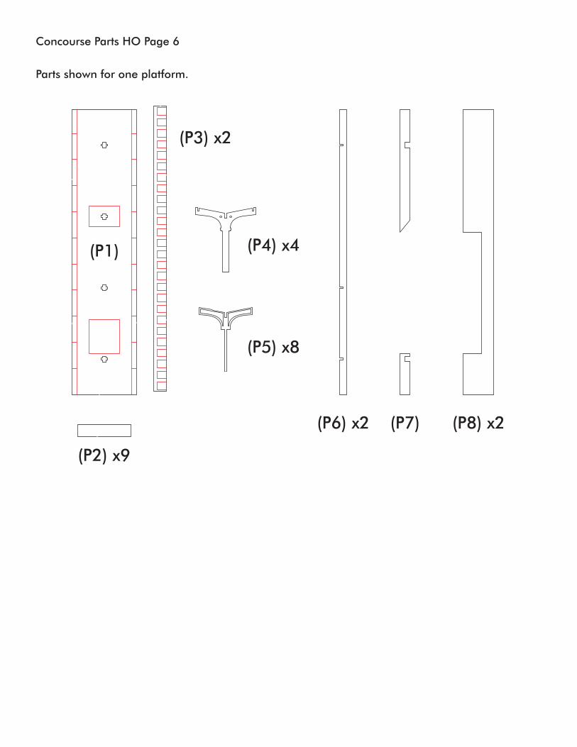
(P3) x2
(P4) x4
(P6) x2 (P8) x2(P7)
(P5) x8
(P1)
(P2) x9
Parts shown for one platform.
Concourse Parts HO Page 6


Concourse - Floor - HO Scale 1 of 4 pages.

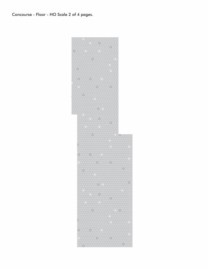
Concourse - Floor - HO Scale 2 of 4 pages.


Concourse - Floor - HO Scale 3 of 4 pages.

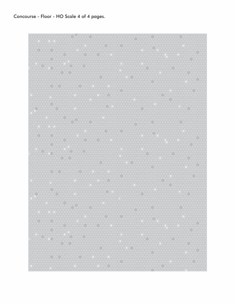
Concourse - Floor - HO Scale 4 of 4 pages.